EP4140770A1 - Tire with shoulder reinforcement - Google Patents
Tire with shoulder reinforcement Download PDFInfo
- Publication number
- EP4140770A1 EP4140770A1 EP22191643.0A EP22191643A EP4140770A1 EP 4140770 A1 EP4140770 A1 EP 4140770A1 EP 22191643 A EP22191643 A EP 22191643A EP 4140770 A1 EP4140770 A1 EP 4140770A1
- Authority
- EP
- European Patent Office
- Prior art keywords
- cords
- tire
- full
- construction
- previous
- Prior art date
- Legal status (The legal status is an assumption and is not a legal conclusion. Google has not performed a legal analysis and makes no representation as to the accuracy of the status listed.)
- Granted
Links
Images


Classifications
-
- B—PERFORMING OPERATIONS; TRANSPORTING
- B60—VEHICLES IN GENERAL
- B60C—VEHICLE TYRES; TYRE INFLATION; TYRE CHANGING; CONNECTING VALVES TO INFLATABLE ELASTIC BODIES IN GENERAL; DEVICES OR ARRANGEMENTS RELATED TO TYRES
- B60C9/00—Reinforcements or ply arrangement of pneumatic tyres
- B60C9/005—Reinforcements made of different materials, e.g. hybrid or composite cords
-
- B—PERFORMING OPERATIONS; TRANSPORTING
- B60—VEHICLES IN GENERAL
- B60C—VEHICLE TYRES; TYRE INFLATION; TYRE CHANGING; CONNECTING VALVES TO INFLATABLE ELASTIC BODIES IN GENERAL; DEVICES OR ARRANGEMENTS RELATED TO TYRES
- B60C9/00—Reinforcements or ply arrangement of pneumatic tyres
- B60C9/18—Structure or arrangement of belts or breakers, crown-reinforcing or cushioning layers
- B60C9/20—Structure or arrangement of belts or breakers, crown-reinforcing or cushioning layers built-up from rubberised plies each having all cords arranged substantially parallel
- B60C9/22—Structure or arrangement of belts or breakers, crown-reinforcing or cushioning layers built-up from rubberised plies each having all cords arranged substantially parallel the plies being arranged with all cords disposed along the circumference of the tyre
-
- B—PERFORMING OPERATIONS; TRANSPORTING
- B29—WORKING OF PLASTICS; WORKING OF SUBSTANCES IN A PLASTIC STATE IN GENERAL
- B29D—PRODUCING PARTICULAR ARTICLES FROM PLASTICS OR FROM SUBSTANCES IN A PLASTIC STATE
- B29D30/00—Producing pneumatic or solid tyres or parts thereof
- B29D30/02—Solid tyres ; Moulds therefor
-
- B—PERFORMING OPERATIONS; TRANSPORTING
- B60—VEHICLES IN GENERAL
- B60C—VEHICLE TYRES; TYRE INFLATION; TYRE CHANGING; CONNECTING VALVES TO INFLATABLE ELASTIC BODIES IN GENERAL; DEVICES OR ARRANGEMENTS RELATED TO TYRES
- B60C9/00—Reinforcements or ply arrangement of pneumatic tyres
- B60C9/0042—Reinforcements made of synthetic materials
-
- B—PERFORMING OPERATIONS; TRANSPORTING
- B60—VEHICLES IN GENERAL
- B60C—VEHICLE TYRES; TYRE INFLATION; TYRE CHANGING; CONNECTING VALVES TO INFLATABLE ELASTIC BODIES IN GENERAL; DEVICES OR ARRANGEMENTS RELATED TO TYRES
- B60C9/00—Reinforcements or ply arrangement of pneumatic tyres
- B60C9/18—Structure or arrangement of belts or breakers, crown-reinforcing or cushioning layers
- B60C9/20—Structure or arrangement of belts or breakers, crown-reinforcing or cushioning layers built-up from rubberised plies each having all cords arranged substantially parallel
- B60C9/2003—Structure or arrangement of belts or breakers, crown-reinforcing or cushioning layers built-up from rubberised plies each having all cords arranged substantially parallel characterised by the materials of the belt cords
-
- B—PERFORMING OPERATIONS; TRANSPORTING
- B60—VEHICLES IN GENERAL
- B60C—VEHICLE TYRES; TYRE INFLATION; TYRE CHANGING; CONNECTING VALVES TO INFLATABLE ELASTIC BODIES IN GENERAL; DEVICES OR ARRANGEMENTS RELATED TO TYRES
- B60C9/00—Reinforcements or ply arrangement of pneumatic tyres
- B60C2009/0071—Reinforcements or ply arrangement of pneumatic tyres characterised by special physical properties of the reinforcements
- B60C2009/0092—Twist structure
-
- B—PERFORMING OPERATIONS; TRANSPORTING
- B60—VEHICLES IN GENERAL
- B60C—VEHICLE TYRES; TYRE INFLATION; TYRE CHANGING; CONNECTING VALVES TO INFLATABLE ELASTIC BODIES IN GENERAL; DEVICES OR ARRANGEMENTS RELATED TO TYRES
- B60C9/00—Reinforcements or ply arrangement of pneumatic tyres
- B60C9/18—Structure or arrangement of belts or breakers, crown-reinforcing or cushioning layers
- B60C9/20—Structure or arrangement of belts or breakers, crown-reinforcing or cushioning layers built-up from rubberised plies each having all cords arranged substantially parallel
- B60C2009/2035—Structure or arrangement of belts or breakers, crown-reinforcing or cushioning layers built-up from rubberised plies each having all cords arranged substantially parallel built-up by narrow strips
-
- B—PERFORMING OPERATIONS; TRANSPORTING
- B60—VEHICLES IN GENERAL
- B60C—VEHICLE TYRES; TYRE INFLATION; TYRE CHANGING; CONNECTING VALVES TO INFLATABLE ELASTIC BODIES IN GENERAL; DEVICES OR ARRANGEMENTS RELATED TO TYRES
- B60C9/00—Reinforcements or ply arrangement of pneumatic tyres
- B60C9/18—Structure or arrangement of belts or breakers, crown-reinforcing or cushioning layers
- B60C9/20—Structure or arrangement of belts or breakers, crown-reinforcing or cushioning layers built-up from rubberised plies each having all cords arranged substantially parallel
- B60C2009/2038—Structure or arrangement of belts or breakers, crown-reinforcing or cushioning layers built-up from rubberised plies each having all cords arranged substantially parallel using lateral belt strips at belt edges, e.g. edge bands
-
- B—PERFORMING OPERATIONS; TRANSPORTING
- B60—VEHICLES IN GENERAL
- B60C—VEHICLE TYRES; TYRE INFLATION; TYRE CHANGING; CONNECTING VALVES TO INFLATABLE ELASTIC BODIES IN GENERAL; DEVICES OR ARRANGEMENTS RELATED TO TYRES
- B60C9/00—Reinforcements or ply arrangement of pneumatic tyres
- B60C9/18—Structure or arrangement of belts or breakers, crown-reinforcing or cushioning layers
- B60C9/20—Structure or arrangement of belts or breakers, crown-reinforcing or cushioning layers built-up from rubberised plies each having all cords arranged substantially parallel
- B60C2009/2074—Physical properties or dimension of the belt cord
- B60C2009/2077—Diameters of the cords; Linear density thereof
-
- B—PERFORMING OPERATIONS; TRANSPORTING
- B60—VEHICLES IN GENERAL
- B60C—VEHICLE TYRES; TYRE INFLATION; TYRE CHANGING; CONNECTING VALVES TO INFLATABLE ELASTIC BODIES IN GENERAL; DEVICES OR ARRANGEMENTS RELATED TO TYRES
- B60C9/00—Reinforcements or ply arrangement of pneumatic tyres
- B60C9/18—Structure or arrangement of belts or breakers, crown-reinforcing or cushioning layers
- B60C9/20—Structure or arrangement of belts or breakers, crown-reinforcing or cushioning layers built-up from rubberised plies each having all cords arranged substantially parallel
- B60C2009/2074—Physical properties or dimension of the belt cord
- B60C2009/2096—Twist structures
-
- B—PERFORMING OPERATIONS; TRANSPORTING
- B60—VEHICLES IN GENERAL
- B60C—VEHICLE TYRES; TYRE INFLATION; TYRE CHANGING; CONNECTING VALVES TO INFLATABLE ELASTIC BODIES IN GENERAL; DEVICES OR ARRANGEMENTS RELATED TO TYRES
- B60C9/00—Reinforcements or ply arrangement of pneumatic tyres
- B60C9/18—Structure or arrangement of belts or breakers, crown-reinforcing or cushioning layers
- B60C9/20—Structure or arrangement of belts or breakers, crown-reinforcing or cushioning layers built-up from rubberised plies each having all cords arranged substantially parallel
- B60C9/22—Structure or arrangement of belts or breakers, crown-reinforcing or cushioning layers built-up from rubberised plies each having all cords arranged substantially parallel the plies being arranged with all cords disposed along the circumference of the tyre
- B60C2009/2214—Structure or arrangement of belts or breakers, crown-reinforcing or cushioning layers built-up from rubberised plies each having all cords arranged substantially parallel the plies being arranged with all cords disposed along the circumference of the tyre characterised by the materials of the zero degree ply cords
-
- B—PERFORMING OPERATIONS; TRANSPORTING
- B60—VEHICLES IN GENERAL
- B60C—VEHICLE TYRES; TYRE INFLATION; TYRE CHANGING; CONNECTING VALVES TO INFLATABLE ELASTIC BODIES IN GENERAL; DEVICES OR ARRANGEMENTS RELATED TO TYRES
- B60C9/00—Reinforcements or ply arrangement of pneumatic tyres
- B60C9/18—Structure or arrangement of belts or breakers, crown-reinforcing or cushioning layers
- B60C9/20—Structure or arrangement of belts or breakers, crown-reinforcing or cushioning layers built-up from rubberised plies each having all cords arranged substantially parallel
- B60C9/22—Structure or arrangement of belts or breakers, crown-reinforcing or cushioning layers built-up from rubberised plies each having all cords arranged substantially parallel the plies being arranged with all cords disposed along the circumference of the tyre
- B60C2009/2252—Physical properties or dimension of the zero degree ply cords
- B60C2009/2257—Diameters of the cords; Linear density thereof
-
- B—PERFORMING OPERATIONS; TRANSPORTING
- B60—VEHICLES IN GENERAL
- B60C—VEHICLE TYRES; TYRE INFLATION; TYRE CHANGING; CONNECTING VALVES TO INFLATABLE ELASTIC BODIES IN GENERAL; DEVICES OR ARRANGEMENTS RELATED TO TYRES
- B60C9/00—Reinforcements or ply arrangement of pneumatic tyres
- B60C9/18—Structure or arrangement of belts or breakers, crown-reinforcing or cushioning layers
- B60C9/20—Structure or arrangement of belts or breakers, crown-reinforcing or cushioning layers built-up from rubberised plies each having all cords arranged substantially parallel
- B60C9/22—Structure or arrangement of belts or breakers, crown-reinforcing or cushioning layers built-up from rubberised plies each having all cords arranged substantially parallel the plies being arranged with all cords disposed along the circumference of the tyre
- B60C2009/2252—Physical properties or dimension of the zero degree ply cords
- B60C2009/2295—Physical properties or dimension of the zero degree ply cords with different cords in the same layer
-
- B—PERFORMING OPERATIONS; TRANSPORTING
- B60—VEHICLES IN GENERAL
- B60C—VEHICLE TYRES; TYRE INFLATION; TYRE CHANGING; CONNECTING VALVES TO INFLATABLE ELASTIC BODIES IN GENERAL; DEVICES OR ARRANGEMENTS RELATED TO TYRES
- B60C2200/00—Tyres specially adapted for particular applications
- B60C2200/02—Tyres specially adapted for particular applications for aircrafts
Definitions
- the present invention relates to pneumatic and non-pneumatic tires and, more specifically, to tires for aircraft service having a shoulder reinforcement or to other tires with a shoulder reinforcement such as UHP passenger tires or race tires.
- Tires for service on aircraft landing gears are exposed to severe operating conditions of load and acceleration/speed.
- aviation tires coupled with the landing gears of large commercial airliners are susceptible to severe deformation upon landing, takeoffs, and controlled movement of the aircraft under its own power while on the ground (e.g., taxiing, parking, etc.).
- Loss of a landing gear tire on takeoff e.g., a blowout, mechanical failure, etc.
- Loss of a landing gear tire upon landing may result in an aborted take-off or an emergency landing.
- Loss of a landing gear tire upon landing may result in an inability to halt the airliner's momentum, leading to runway overshoot.
- Airliners often elevate tire temperature by taxiing long distances and/or by taxiing at high speed, which may increase the susceptibility to blowouts during takeoff or after landing.
- the belt package incorporated into conventional aviation tires includes a number of cut belt layers and a number of spiral wound layers formed from cord reinforced strip(s) wound about the circumference of belt layers of the tire with a zero degree spiral overlay.
- the spiral wound layers terminate proximate the tire shoulder of the tire with little or no overlap, as the winding direction is reversed to apply the successive spiral wound layers.
- the invention relates to a tire in accordance with claim 1 and to a method in accordance with claim 15.
- a tire in accordance with a preferred aspect of the invention includes a carcass, a tread disposed radially outward of the carcass, a sidewall including a shoulder extends toward the tread, and a reinforcing structure positioned radially between the carcass and the tread.
- the reinforcing structure includes one or a plurality of belts extending axially toward the shoulder and an overlapping spiral wound strip positioned at a radially outermost portion of the reinforcing structure.
- the overlapping spiral wound strip includes a uniform width having groups of four first cords with a single second cord therebetween.
- the first cords include a hybrid construction, and the second cords include a single material construction.
- a method of constructing a tire in accordance with a preferred aspect of the invention includes the steps of: axially extending a carcass from a first bead portion to a second bead portion, axially extending a tread radially outward of the carcass, extending a sidewall radially outward to a shoulder adjacent the tread; positioning a reinforcing structure radially between the carcass and the tread, spirally winding an overlapping strip at a radially outermost portion of the reinforcing structure.
- the overlapping strip includes a uniform width having groups of four first cords with a single second cord therebetween.
- the first cords include a hybrid construction, and the second cords includes a single material construction.
- the first cords have a hybrid construction of nylon and aramid.
- the second cords have a full nylon construction.
- the first cords have a hybrid construction
- the second cords have a 1400dtex/2 single material construction.
- the first cords have a full nylon construction
- the second cords have a 1840 dtex/3 full rayon construction.
- the first cords have a full aramid construction.
- the second cords have a 2 + 4 full nylon construction.
- Axial and “axially” means the lines or directions that are parallel to the axis of rotation of the tire.
- Carcass means the tire structure apart from the belt structure, tread, undertread, and sidewall rubber over the plies, but including the beads.
- Core means one of the reinforcement strands which the plies in the tire comprise.
- “Crown” refers to substantially the outer circumference of a tire where the tread is disposed.
- Circumferential means circular lines or directions extending along the surface of the sidewall perpendicular to the axial direction.
- Equatorial plane means the plane perpendicular to the tire's axis of rotation and passing through the center of its tread.
- Inner means toward the inside of the tire.
- “Lateral” means a direction parallel to the axial direction, as in across the width of the tread or crown region.
- Pneumatic tire means a laminated mechanical device of generally toroidal shape, usually an open-torus having beads and a tread and made of rubber, chemicals, fabric and steel or other materials.
- Ring and radially mean directions radially toward or away from the axis of rotation of the tire.
- Shader means the upper portion of the sidewall just below the tread edge.
- “Sidewall” means that portion of a tire between the tread and the bead area.
- Thread means a molded rubber component which, when bonded to a tire casing, includes that portion of the tire that comes into contact with the road when the tire is normally inflated and under normal load.
- an example pneumatic aviation tire 10 suitable for airliner service as a nose gear tire for instance includes a carcass 12, a ground-engaging tread 14, a sidewall 16, and a shoulder 18 defined by the junction of the sidewall 16 and the tread 14.
- the tread 14 When mounted on the airliner, the tread 14 provides traction and the tire 10 contains a fluid (e.g., air, nitrogen, etc.) that sustains part of the airliner load.
- the example tire 10 preferably has a mirror symmetry reflecting about an equatorial plane 19 bisecting tire 10.
- a belt package Arranged between the carcass 12 and the tread 14 is a belt package, generally indicated by reference numeral 20, comprising one belt, two belts or preferably a plurality of, for example five, six or seven, individual cut belt plies or layers 22, 24, 26, 28, 30, 32 and a plurality of, for example one, two or three, spiral wound belt layers 34, 36 positioned radially-outward from the one or more cut belt layers 22, 24, 26, 28, 30, 32.
- the number of cut belt layers and spiral wound layers in the belt package 20 may vary according to the tire construction. If the tire 10 is a passenger tire, it may be sufficient for instance to use just one or two belt layers, i.e., only one or two of the individual cut belt plies or layers 22, 24, 26, 28, 30, 32, in the belt package 20.
- both of the spiral wound belt layers 34, 36 are formed by a continuous rubberized flat strip 38 that is wound circumferentially (e.g., with a -5 degree to +5 degree spiral overlay) about the tire 10.
- the overlay 34, 36 extends one tire shoulder 18 to the other tire shoulder (not shown).
- the flat strip 38 is reinforced with multiple embedded preferably high modulus, preferably essentially inextensible, cords 40 of, for example, nylon, rayon, polyester, aramid, glass, and/or metal disposed spatially with a substantially parallel arrangement of one to another and covered by an elastomer matrix, such as a cured rubber casing.
- the width Ws of flat strip 38 preferably ranges from 6 mm to 20 mm or from 6 to 14 mm such as 10 mm.
- the thickness of the flat strip 38 may approximate several millimeters.
- the density of cords 40 of the flat strip 38 is preferably from 18 to 22 per 2.54 cm ("ends per inch").
- the flat strip 38 is wound circumferentially about a crowned building drum with the flat strip 38 being shifted by a transverse, or axial, distance approximately equal to, or slightly greater than, the width Ws with each individual turn.
- the axial dimension of the one or more cut belt layers 22, 24, 26, 28, 30, 32 is preferably selected such that corresponding lateral side edges are tiered or staggered with an overlapping relationship near the tire shoulder 18.
- the cut belt layer 22 preferably extends laterally/axially for a greater lateral distance from the equatorial plane 19 than the cut belt layer 24 so that the terminal side edge of the cut belt layer 24 overlaps between layers 22 and 26.
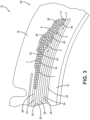
- Each of the spiral wound shoulder layers 42, 44, 46 is preferably defined by a single circumferential flat strip, similar to the flat strip 38, in which adjacent turns are shifted laterally by less than one strip width (Ws) so that the shoulder layers 42, 44, 46 have a partially overlapping, or staggered relationship ( FIG. 3 ).
- the winding pitch for spiral wound shoulder layers 42, 44, 46 is preferably less than one strip width (Ws) per revolution.
- the remaining spiral wound shoulder layers 48, 50, 52, 54 are preferably applied with a winding pitch equal to one strip width (Ws) per revolution such that there is no overlapping build up in the tire crown region beyond the overlap afforded by spiral wound belt layers 34, 36.
- the lateral shift of less than one strip width (Ws) is shown in FIGS. 1-3 as adjacent turns of the flat strip 38 contribute to the partially overlapping relationship. In a central region of the tire shoulder 18, an overlapping relationship may thereby be established to provide an ultimate thickness equivalent to for instance six strip thicknesses.
- the first spiral wound belt layer 34 is applied to the tire 10.
- the winding pitch is changed from greater than or equal to one strip width (Ws) per revolution (e.g., a -5 degree to +5 degree pitch) to a winding pitch that is less than one strip width (Ws) per revolution.
- the spiral wound shoulder layers 42, 44, 46 is shifted laterally by approximately 0.2 of the strip width (Ws) per revolution.
- the spiral wound shoulder layers 42, 44, 46 are for instance applied serially or sequentially from left to right, as best visible in FIG. 1 .
- the spiral wound shoulder layers 48, 50 are preferably applied with a winding pitch of approximately zero degrees so that the shoulder layers 48, 50 roughly overlap the shoulder layer 48. Then, the winding pitch is preferably reverted to greater than or equal to one strip width (Ws) per revolution.
- the spiral wound shoulder layer 52 is preferably applied with a unitary winding pitch of one strip width (Ws), in an opposite or reverse winding direction from the shoulder layers 42, 44, 46. After the shoulder layer 52 is applied, the circumferential turns of the flat strip 38 transitions into forming the spiral wound belt layer 36.
- another set of spiral wound shoulder layers (not shown but similar to spiral wound shoulder layers 42, 44, 46, 48, 50, 52) are preferably applied to tire 10.
- the belt package 60 for an example tire (not shown, but similar to the tire 10 of FIGS. 1-3 ) includes one, two or preferably a plurality of cut belts 62, 64 and a plurality of spiral wound belt layers 66, 68, 70, 72, 74, 76 wound with a zero degree spiral.
- the laterally outermost turn of the spiral wound belt layer 66 is preferably aligned radially with the free side edge of the underlying cut belt 64.
- the laterally outermost turn of the spiral wound belt layer 68 are preferably shifted laterally by less than one strip width (Ws), although the winding pitch remains constant at greater than or equal to about one strip width (Ws).
- Each successive spiral wound belt layer 70, 72, 74, 76 may likewise be shifted laterally by less than one strip width (Ws) while the winding pitch remains constant at greater than or equal to about one strip width (Ws).
- Ws strip width
- an initial strip turn of each spiral wound belt layer 66, 68, 70, 72, 74, 76 may be shifted laterally by less than one strip width (Ws) so that radially adjacent pairs of the spiral wound belt layers 66, 68, 70, 72, 74, 76 only partially overlap.
- Alternating spiral wound belt layers for example spiral wound belt layers 66, 68, 72, preferably include multiple overlapping initial turns of the flat strip 38 wound with a zero pitch.
- two cut belts and six spiral wound belt layers are provided in the belt package 60 and the lateral shift distance for successive spiral wound belt layers is about 0.33 of the strip width (Ws).
- the overlapping turns of flat strip 38 at the lateral edge of the spiral wound belt layers create a tiered arrangement such that the lateral shift in the starting location for successive spiral wound belt layers 66, 68, 70, 72, 74, 76 and the lateral edges among successive spiral wound belt layers 66, 68, 70, 72, 74, 76 are not coincident.
- the spiral wound belt layer 66 contributes for instance three overlapping spiral wound shoulder layers.
- the spiral wound belt layer 68 for instance contributes one partially overlapping spiral wound shoulder layer.
- the spiral wound belt layer 70 for instance contributes three partially overlapping spiral wound shoulder layers.
- an overlay construction such as above described 34, 36, 38, includes multiple cord materials.
- Current manufacturing methods allow an overlay construction in accordance with the present invention to include multiple reinforcement cords co-extruded in a single step.
- An overlay strip such as the flat strip 38, thus preferably comprises two or more single end dipped cords of different materials.
- the overlay strip preferably has a width between 10 mm and 15 mm, or 10 mm.
- the overlay strip width preferably includes seven hybrid cords of aramid/nylon and two nylon cords, in place of eight cords of hybrid material for a conventional overlay strip, such as the spiral layers 34, 36 and the flat strip 38.
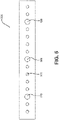
- the width of an example overlay strip 500 in accordance with the present invention includes groups of four first cords 510 with a single second cord 520 therebetween.
- 2 to 8 such first cords 510 with 1 to 4 such second singe cords 520 therebetween may be used.
- the first cords 510 preferably include a hybrid construction, a full nylon construction, or a full aramid constriction.
- the second cords 520 preferably include a hybrid construction, a full nylon construction, or a full aramid constriction.
- the first cords 510 are a hybrid cord of nylon and aramid, and the second cords 520 are full nylon cords.
- the first cords 510 are of a hybrid construction and the second cords 520 are of a single material construction, preferably a 1400dtex/2 single material construction.
- the first cords 510 are full nylon cords and the second cords 520 are of a full rayon construction, preferably of a 1840 dtex/3 full rayon construction.
- the first cords 510 are of full aramid construction and the second cords 520 are of a 2 + 4 full nylon construction.
Landscapes
- Engineering & Computer Science (AREA)
- Mechanical Engineering (AREA)
- Tires In General (AREA)
Abstract
Description
- The present invention relates to pneumatic and non-pneumatic tires and, more specifically, to tires for aircraft service having a shoulder reinforcement or to other tires with a shoulder reinforcement such as UHP passenger tires or race tires.
- Tires for service on aircraft landing gears are exposed to severe operating conditions of load and acceleration/speed. In particular, aviation tires coupled with the landing gears of large commercial airliners are susceptible to severe deformation upon landing, takeoffs, and controlled movement of the aircraft under its own power while on the ground (e.g., taxiing, parking, etc.). Loss of a landing gear tire on takeoff (e.g., a blowout, mechanical failure, etc.) may result in an aborted take-off or an emergency landing. Loss of a landing gear tire upon landing may result in an inability to halt the airliner's momentum, leading to runway overshoot. Airliners often elevate tire temperature by taxiing long distances and/or by taxiing at high speed, which may increase the susceptibility to blowouts during takeoff or after landing.
- Typically, the belt package incorporated into conventional aviation tires includes a number of cut belt layers and a number of spiral wound layers formed from cord reinforced strip(s) wound about the circumference of belt layers of the tire with a zero degree spiral overlay. The spiral wound layers terminate proximate the tire shoulder of the tire with little or no overlap, as the winding direction is reversed to apply the successive spiral wound layers.
- One conventional approach for improving tire durability is a uniform increase in the number of belt layers from crown to shoulder. However, this approach may result in significant tire weight increases. Tire weight increases from the added layers is contrary to another tire design parameter for minimizing the net weight of the airliner. Increasing the number of belt layers uniformly between the crown and the shoulder also significantly increases the tire's production cost (e.g., more material, more complexity, more waste, etc.). For these and other reasons, it would be desirable to provide a lightweight tire for airliner landing gears characterized by improved durability and greater load capability.
- The invention relates to a tire in accordance with
claim 1 and to a method in accordance with claim 15. - Dependent claims refer to preferred embodiments of the invention.
- A tire in accordance with a preferred aspect of the invention includes a carcass, a tread disposed radially outward of the carcass, a sidewall including a shoulder extends toward the tread, and a reinforcing structure positioned radially between the carcass and the tread. The reinforcing structure includes one or a plurality of belts extending axially toward the shoulder and an overlapping spiral wound strip positioned at a radially outermost portion of the reinforcing structure. The overlapping spiral wound strip includes a uniform width having groups of four first cords with a single second cord therebetween. The first cords include a hybrid construction, and the second cords include a single material construction.
- A method of constructing a tire in accordance with a preferred aspect of the invention includes the steps of: axially extending a carcass from a first bead portion to a second bead portion, axially extending a tread radially outward of the carcass, extending a sidewall radially outward to a shoulder adjacent the tread; positioning a reinforcing structure radially between the carcass and the tread, spirally winding an overlapping strip at a radially outermost portion of the reinforcing structure. The overlapping strip includes a uniform width having groups of four first cords with a single second cord therebetween. The first cords include a hybrid construction, and the second cords includes a single material construction.
- According to a preferred aspect of the invention, the first cords have a hybrid construction of nylon and aramid.
- According to a preferred aspect of the invention, the second cords have a full nylon construction.
- According to a preferred aspect of the invention, the first cords have a hybrid construction, and the second cords have a 1400dtex/2 single material construction.
- According to a preferred aspect of the invention, the first cords have a full nylon construction, and the second cords have a 1840 dtex/3 full rayon construction.
- According to a preferred aspect of the invention, the first cords have a full aramid construction.
- According to a preferred aspect of the invention, the second cords have a 2 + 4 full nylon construction.
- "Axial" and "axially" means the lines or directions that are parallel to the axis of rotation of the tire.
- "Carcass" means the tire structure apart from the belt structure, tread, undertread, and sidewall rubber over the plies, but including the beads.
- "Cord" means one of the reinforcement strands which the plies in the tire comprise.
- "Crown" refers to substantially the outer circumference of a tire where the tread is disposed.
- "Circumferential" means circular lines or directions extending along the surface of the sidewall perpendicular to the axial direction.
- "Equatorial plane (EP)" means the plane perpendicular to the tire's axis of rotation and passing through the center of its tread.
- "Inner" means toward the inside of the tire.
- "Lateral" means a direction parallel to the axial direction, as in across the width of the tread or crown region.
- "Outer" means toward the tire's exterior.
- "Pneumatic tire" means a laminated mechanical device of generally toroidal shape, usually an open-torus having beads and a tread and made of rubber, chemicals, fabric and steel or other materials.
- "Radial" and "radially" mean directions radially toward or away from the axis of rotation of the tire.
- "Shoulder" means the upper portion of the sidewall just below the tread edge.
- "Sidewall" means that portion of a tire between the tread and the bead area.
- "Tread" means a molded rubber component which, when bonded to a tire casing, includes that portion of the tire that comes into contact with the road when the tire is normally inflated and under normal load.
- The invention will be described by way of example and with reference to the accompanying drawings in which:
-
FIG. 1 is a schematic view of an example belt package for use with the present invention; -
FIG. 2 is a schematic cross-sectional view of the example tire ofFIG. 1 ; -
FIG. 3 is a schematic enlarged view of a portion ofFIG. 2 ; -
FIG. 4 is a schematic view of another example belt package for use with the present invention; and -
FIG. 5 is a schematic cross-sectional view of an overlay strip in accordance with the present invention. - With reference to
FIGS. 1-3 , an examplepneumatic aviation tire 10 suitable for airliner service as a nose gear tire for instance includes acarcass 12, a ground-engaging tread 14, asidewall 16, and ashoulder 18 defined by the junction of thesidewall 16 and thetread 14. When mounted on the airliner, thetread 14 provides traction and thetire 10 contains a fluid (e.g., air, nitrogen, etc.) that sustains part of the airliner load. Theexample tire 10 preferably has a mirror symmetry reflecting about anequatorial plane 19 bisectingtire 10. Arranged between thecarcass 12 and thetread 14 is a belt package, generally indicated byreference numeral 20, comprising one belt, two belts or preferably a plurality of, for example five, six or seven, individual cut belt plies orlayers wound belt layers cut belt layers belt package 20 may vary according to the tire construction. If thetire 10 is a passenger tire, it may be sufficient for instance to use just one or two belt layers, i.e., only one or two of the individual cut belt plies orlayers belt package 20. - As best shown in
FIGS. 1 and3 , both of the spiralwound belt layers flat strip 38 that is wound circumferentially (e.g., with a -5 degree to +5 degree spiral overlay) about thetire 10. Theoverlay tire shoulder 18 to the other tire shoulder (not shown). Theflat strip 38 is reinforced with multiple embedded preferably high modulus, preferably essentially inextensible, cords 40 of, for example, nylon, rayon, polyester, aramid, glass, and/or metal disposed spatially with a substantially parallel arrangement of one to another and covered by an elastomer matrix, such as a cured rubber casing. The width Ws offlat strip 38 preferably ranges from 6 mm to 20 mm or from 6 to 14 mm such as 10 mm. The thickness of theflat strip 38 may approximate several millimeters. The density of cords 40 of theflat strip 38 is preferably from 18 to 22 per 2.54 cm ("ends per inch"). During construction oftire 10, theflat strip 38 is wound circumferentially about a crowned building drum with theflat strip 38 being shifted by a transverse, or axial, distance approximately equal to, or slightly greater than, the width Ws with each individual turn. - The axial dimension of the one or more cut belt layers 22, 24, 26, 28, 30, 32 is preferably selected such that corresponding lateral side edges are tiered or staggered with an overlapping relationship near the
tire shoulder 18. For example, thecut belt layer 22 preferably extends laterally/axially for a greater lateral distance from theequatorial plane 19 than thecut belt layer 24 so that the terminal side edge of thecut belt layer 24 overlaps betweenlayers - A plurality of overlapping spiral wound shoulder layers 42, 44, 46, 48, 50, 52, 54, preferably 3 to 8 or 5 to 7 such shoulder layers, is provided in the
tire shoulder 18. - Each of the spiral wound shoulder layers 42, 44, 46 is preferably defined by a single circumferential flat strip, similar to the
flat strip 38, in which adjacent turns are shifted laterally by less than one strip width (Ws) so that the shoulder layers 42, 44, 46 have a partially overlapping, or staggered relationship (FIG. 3 ). In other words, the winding pitch for spiral wound shoulder layers 42, 44, 46 is preferably less than one strip width (Ws) per revolution. The remaining spiral wound shoulder layers 48, 50, 52, 54 are preferably applied with a winding pitch equal to one strip width (Ws) per revolution such that there is no overlapping build up in the tire crown region beyond the overlap afforded by spiral wound belt layers 34, 36. The lateral shift of less than one strip width (Ws) is shown inFIGS. 1-3 as adjacent turns of theflat strip 38 contribute to the partially overlapping relationship. In a central region of thetire shoulder 18, an overlapping relationship may thereby be established to provide an ultimate thickness equivalent to for instance six strip thicknesses. - With continued reference to
FIGS. 1-3 , to apply the spiral wound shoulder layers 42, 44, 46, 48, 50, 52, 54, the first spiral woundbelt layer 34 is applied to thetire 10. After theshoulder layer 54 is applied, the winding pitch is changed from greater than or equal to one strip width (Ws) per revolution (e.g., a -5 degree to +5 degree pitch) to a winding pitch that is less than one strip width (Ws) per revolution. In theexample belt package 20 ofFIGS. 1-3 , the spiral wound shoulder layers 42, 44, 46 is shifted laterally by approximately 0.2 of the strip width (Ws) per revolution. The spiral wound shoulder layers 42, 44, 46 are for instance applied serially or sequentially from left to right, as best visible inFIG. 1 . The spiral wound shoulder layers 48, 50 are preferably applied with a winding pitch of approximately zero degrees so that the shoulder layers 48, 50 roughly overlap theshoulder layer 48. Then, the winding pitch is preferably reverted to greater than or equal to one strip width (Ws) per revolution. The spiral woundshoulder layer 52 is preferably applied with a unitary winding pitch of one strip width (Ws), in an opposite or reverse winding direction from the shoulder layers 42, 44, 46. After theshoulder layer 52 is applied, the circumferential turns of theflat strip 38 transitions into forming the spiral woundbelt layer 36. At the tire shoulder opposite thetire shoulder 18, another set of spiral wound shoulder layers (not shown but similar to spiral wound shoulder layers 42, 44, 46, 48, 50, 52) are preferably applied totire 10. - With reference to
FIG. 4 , anotherexample belt package 60 for use with the present invention is shown. Thebelt package 60 for an example tire (not shown, but similar to thetire 10 ofFIGS. 1-3 ) includes one, two or preferably a plurality ofcut belts belt layer 66 is preferably aligned radially with the free side edge of theunderlying cut belt 64. The laterally outermost turn of the spiral woundbelt layer 68 are preferably shifted laterally by less than one strip width (Ws), although the winding pitch remains constant at greater than or equal to about one strip width (Ws). Each successive spiral woundbelt layer FIG. 1 ), an initial strip turn of each spiral woundbelt layer flat strip 38 wound with a zero pitch. In the example shown, two cut belts and six spiral wound belt layers are provided in thebelt package 60 and the lateral shift distance for successive spiral wound belt layers is about 0.33 of the strip width (Ws). - The overlapping turns of
flat strip 38 at the lateral edge of the spiral wound belt layers create a tiered arrangement such that the lateral shift in the starting location for successive spiral wound belt layers 66, 68, 70, 72, 74, 76 and the lateral edges among successive spiral wound belt layers 66, 68, 70, 72, 74, 76 are not coincident. The spiral woundbelt layer 66 contributes for instance three overlapping spiral wound shoulder layers. The spiral woundbelt layer 68 for instance contributes one partially overlapping spiral wound shoulder layer. The spiral woundbelt layer 70 for instance contributes three partially overlapping spiral wound shoulder layers. - In accordance with the present invention, an overlay construction, such as above described 34, 36, 38, includes multiple cord materials. Current manufacturing methods allow an overlay construction in accordance with the present invention to include multiple reinforcement cords co-extruded in a single step. An overlay strip, such as the
flat strip 38, thus preferably comprises two or more single end dipped cords of different materials. The overlay strip preferably has a width between 10 mm and 15 mm, or 10 mm. For example, the overlay strip width preferably includes seven hybrid cords of aramid/nylon and two nylon cords, in place of eight cords of hybrid material for a conventional overlay strip, such as the spiral layers 34, 36 and theflat strip 38. - Conventional overlay strips have been made entirely of a single reinforcement material, such as full nylon, hybrid nylon and aramid, or full aramid. The application of single dipped fabrics (made of a single cord type), one at a time, for calendering/slitting operations allows varying cord types within a single overlay strip. Such a combination of different cord materials within a single strip may thereby enhances functional properties while decreasing cost and/or weight of the overlay package. The insertion of one of more full nylon cords into an overlay strip usually made entirely of hybrid cords further increases shrink force at higher speeds when the tire starts to heat-up, leading to a more stable tire circumference at high speeds, with potential benefits in high speed performance.
- As shown in
FIG. 5 , the width of anexample overlay strip 500 in accordance with the present invention includes groups of fourfirst cords 510 with a singlesecond cord 520 therebetween. Alternatively, 2 to 8 suchfirst cords 510 with 1 to 4 suchsecond singe cords 520 therebetween may be used. - The
first cords 510 preferably include a hybrid construction, a full nylon construction, or a full aramid constriction. Thesecond cords 520 preferably include a hybrid construction, a full nylon construction, or a full aramid constriction. - In a first example, the
first cords 510 are a hybrid cord of nylon and aramid, and thesecond cords 520 are full nylon cords. In a second example, thefirst cords 510 are of a hybrid construction and thesecond cords 520 are of a single material construction, preferably a 1400dtex/2 single material construction. In a third example, thefirst cords 510 are full nylon cords and thesecond cords 520 are of a full rayon construction, preferably of a 1840 dtex/3 full rayon construction. In a fourth example, thefirst cords 510 are of full aramid construction and thesecond cords 520 are of a 2 + 4 full nylon construction.
Claims (15)
- A tire comprising a carcass, a tread (14) disposed radially outward of the carcass (12), a sidewall (16) including a shoulder (18) extending toward the tread (14), and a reinforcing structure (20, 60) positioned radially between the carcass (12) and the tread (14), the reinforcing structure (20, 60) including one, two or a plurality of belts (22, 24, 26, 28, 30, 32, 62, 64) extending axially toward the shoulder (18) and an overlapping spirally wound strip (500) positioned at a radially outermost portion of the reinforcing structure (20, 60), characterized in that the overlapping spirally wound strip (500) has a preferably uniform width and comprises groups of from 2 to 8 first cords (510) together with of from 1 to 4 second cords (520) therebetween, the material of the first cords (510) being different from the material of the second cords (520) and/or the diameter of the first cords (510) being different from the diameter of the second cords (520).
- The tire of claim 1 wherein the strip comprises 3, 4 or 5 of said first cords (510) and 1, 2 or 3 of said second cords.
- The tire of claim 2 wherein the strip (500) has four of said first cords (510) and one of said second cords (520).
- The tire of at least one of the previous claims wherein the first cords (510) are of a hybrid cord construction and the second cords (520) are of a single material construction, or wherein the second cords (520) are of a hybrid cord construction and the first cords (510) are of a single material construction
- The tire of at least one of the previous claims wherein the first cords (510) are of a hybrid construction of nylon and aramid.
- The tire of at least one of the previous claims wherein the second cords (520) are of a full nylon construction.
- The tire of at least one of the previous claims wherein the first cords (510) are full nylon cords and the second cords (520) are full aramid cords, or wherein the first cords (510) are full aramid cords and the second cords (520) are full nylon cords.
- The tire of at least one of the previous claims wherein the first cords (510) are full nylon cords and the second cords (520) are full rayon cords, or wherein the first cords (510) are full rayon cords and the second cords (520) are full nylon cords.
- The tire of at least one of the previous claims wherein the second cords (520) are of a 1400dtex/2 single material construction or wherein the second cords (520) are of a 1840 dtex/3 full rayon construction.
- The tire of at least one of the previous claims wherein the first cords (510) are of a full aramid construction.
- The tire of at least one of the previous claims wherein the second cords (520) or of a 2 + 4 full nylon construction.
- The tire of at least one of the previous claims wherein the diameter of the second cords (520) is in a range of from 120% to 220%, preferably 140% to 180%, of the diameter of the first cords (510).
- The tire of at least one of the previous claims wherein the strip (500) has an axial width in a range of from 8 to 20 mm, preferably 10 to 15 mm.
- The tire of at least one of the previous claims wherein the tire is an aircraft tire.
- A method of constructing a tire (10), preferably an aircraft tire, the method comprising the steps: axially extending a carcass (12) from a first bead portion to a second bead portion, disposing a tread (14) radially outward of the carcass (12), providing a sidewall (16) including a shoulder (18) extending toward the tread (14), providing a reinforcing structure (20, 60) and positioning the reinforcing structure (20, 60) radially between the carcass (12) and the tread (14), and spirally winding an overlapping strip (500) at a radially outermost portion of the reinforcing structure (20, 60), characterized in that the overlapping spirally wound strip (500) has a preferably uniform width and comprises groups of from 2 to 8 first cords (510) together with of from 1 to 4 second cords (520) therebetween, the material of the first cords (510) being different from the material of the second cords (520) and/or the radial thickness of the first cords (510) being different from the radial thickness of the second cords (520).
Applications Claiming Priority (1)
| Application Number | Priority Date | Filing Date | Title |
|---|---|---|---|
| US17/411,629 US20230064368A1 (en) | 2021-08-25 | 2021-08-25 | Pneumatic aviation tire |
Publications (2)
| Publication Number | Publication Date |
|---|---|
| EP4140770A1 true EP4140770A1 (en) | 2023-03-01 |
| EP4140770B1 EP4140770B1 (en) | 2024-09-18 |
Family
ID=83049993
Family Applications (1)
| Application Number | Title | Priority Date | Filing Date |
|---|---|---|---|
| EP22191643.0A Active EP4140770B1 (en) | 2021-08-25 | 2022-08-23 | Tire with shoulder reinforcement |
Country Status (2)
| Country | Link |
|---|---|
| US (1) | US20230064368A1 (en) |
| EP (1) | EP4140770B1 (en) |
Citations (3)
| Publication number | Priority date | Publication date | Assignee | Title |
|---|---|---|---|---|
| JP4373099B2 (en) * | 2003-01-16 | 2009-11-25 | 住友ゴム工業株式会社 | Motorcycle tires |
| US9346320B2 (en) * | 2003-06-19 | 2016-05-24 | Pirelli Pneumatici S.P.A. | Tyre with specified belt structure |
| LU100828A1 (en) * | 2016-10-13 | 2018-07-30 | Kordsa Teknik Tekstil As | TOP FLOOR BAND COMPRISING NYLON 6.6 AND PET CABLE ALTERNATE CABLES |
Family Cites Families (3)
| Publication number | Priority date | Publication date | Assignee | Title |
|---|---|---|---|---|
| US5221382A (en) * | 1991-05-10 | 1993-06-22 | The Goodyear Tire & Rubber Company | Pneumatic tire including gas absorbing cords |
| JP3453353B2 (en) * | 2000-11-09 | 2003-10-06 | 住友ゴム工業株式会社 | Pneumatic radial tire |
| JP6260598B2 (en) * | 2015-09-30 | 2018-01-17 | 横浜ゴム株式会社 | Pneumatic tire and manufacturing method thereof |
-
2021
- 2021-08-25 US US17/411,629 patent/US20230064368A1/en active Pending
-
2022
- 2022-08-23 EP EP22191643.0A patent/EP4140770B1/en active Active
Patent Citations (3)
| Publication number | Priority date | Publication date | Assignee | Title |
|---|---|---|---|---|
| JP4373099B2 (en) * | 2003-01-16 | 2009-11-25 | 住友ゴム工業株式会社 | Motorcycle tires |
| US9346320B2 (en) * | 2003-06-19 | 2016-05-24 | Pirelli Pneumatici S.P.A. | Tyre with specified belt structure |
| LU100828A1 (en) * | 2016-10-13 | 2018-07-30 | Kordsa Teknik Tekstil As | TOP FLOOR BAND COMPRISING NYLON 6.6 AND PET CABLE ALTERNATE CABLES |
Also Published As
| Publication number | Publication date |
|---|---|
| EP4140770B1 (en) | 2024-09-18 |
| US20230064368A1 (en) | 2023-03-02 |
Similar Documents
| Publication | Publication Date | Title |
|---|---|---|
| US7950430B2 (en) | Pneumatic aviation tire | |
| EP1518666B1 (en) | A method of manufacturing a tyre belt structure and a tyre incorporating the same | |
| EP2394822B1 (en) | Tire comprising a zigzag belt reinforcing structure, in particular a reduced weight aircraft tire | |
| EP2055508B1 (en) | Pneumatic tyre with increased lower sidewall durability | |
| EP2420396B1 (en) | Pneumatic tire | |
| EP1449680A1 (en) | A tire having a composite belt structure | |
| CN101445023A (en) | A pneumatic tyre and a process to retread a tyre | |
| US20160200147A1 (en) | Reduced weight aircraft tire | |
| EP3290232B1 (en) | Tire with low weight and high burst strength | |
| EP1574362B1 (en) | A pneumatic tire having a crown reinforcement structure with a plurality of adjacent cord reinforced strips and a process to manufacture or retread such a tire | |
| EP2527162B1 (en) | Carcass ply structure for a pneumatic tire | |
| EP2977229B1 (en) | Reduced weight aircraft tire | |
| EP0294484B1 (en) | Method of manufacturing a pneumatic radial tyre | |
| EP4140770B1 (en) | Tire with shoulder reinforcement | |
| EP2199108B1 (en) | Pneumatic tire | |
| EP3825149A1 (en) | Reduced weight aircraft tire | |
| EP3900955B1 (en) | Aircraft pneumatic tire | |
| GB2495167A (en) | Pneumatic tyre | |
| JP4070314B2 (en) | Heavy duty pneumatic radial tires | |
| EP4015243B1 (en) | Tire with protective belt structure | |
| JP2975609B2 (en) | Pneumatic radial tire | |
| US20210146726A1 (en) | Reduced weight aircraft tire | |
| JP2001138712A (en) | Pneumatic radial tire for high-speed heavy load | |
| GB2507196A (en) | Pneumatic tyre |
Legal Events
| Date | Code | Title | Description |
|---|---|---|---|
| PUAI | Public reference made under article 153(3) epc to a published international application that has entered the european phase |
Free format text: ORIGINAL CODE: 0009012 |
|
| STAA | Information on the status of an ep patent application or granted ep patent |
Free format text: STATUS: THE APPLICATION HAS BEEN PUBLISHED |
|
| AK | Designated contracting states |
Kind code of ref document: A1 Designated state(s): AL AT BE BG CH CY CZ DE DK EE ES FI FR GB GR HR HU IE IS IT LI LT LU LV MC MK MT NL NO PL PT RO RS SE SI SK SM TR |
|
| STAA | Information on the status of an ep patent application or granted ep patent |
Free format text: STATUS: REQUEST FOR EXAMINATION WAS MADE |
|
| 17P | Request for examination filed |
Effective date: 20230901 |
|
| RBV | Designated contracting states (corrected) |
Designated state(s): AL AT BE BG CH CY CZ DE DK EE ES FI FR GB GR HR HU IE IS IT LI LT LU LV MC MK MT NL NO PL PT RO RS SE SI SK SM TR |
|
| GRAP | Despatch of communication of intention to grant a patent |
Free format text: ORIGINAL CODE: EPIDOSNIGR1 |
|
| STAA | Information on the status of an ep patent application or granted ep patent |
Free format text: STATUS: GRANT OF PATENT IS INTENDED |
|
| RIC1 | Information provided on ipc code assigned before grant |
Ipc: B60C 9/20 20060101ALN20240326BHEP Ipc: B29D 30/38 20060101ALN20240326BHEP Ipc: B29D 30/02 20060101ALN20240326BHEP Ipc: B60C 9/22 20060101AFI20240326BHEP |
|
| INTG | Intention to grant announced |
Effective date: 20240417 |
|
| GRAS | Grant fee paid |
Free format text: ORIGINAL CODE: EPIDOSNIGR3 |
|
| GRAA | (expected) grant |
Free format text: ORIGINAL CODE: 0009210 |
|
| STAA | Information on the status of an ep patent application or granted ep patent |
Free format text: STATUS: THE PATENT HAS BEEN GRANTED |
|
| AK | Designated contracting states |
Kind code of ref document: B1 Designated state(s): AL AT BE BG CH CY CZ DE DK EE ES FI FR GB GR HR HU IE IS IT LI LT LU LV MC MK MT NL NO PL PT RO RS SE SI SK SM TR |
|
| REG | Reference to a national code |
Ref country code: GB Ref legal event code: FG4D |
|
| REG | Reference to a national code |
Ref country code: CH Ref legal event code: EP |
|
| REG | Reference to a national code |
Ref country code: IE Ref legal event code: FG4D |
|
| REG | Reference to a national code |
Ref country code: DE Ref legal event code: R096 Ref document number: 602022006169 Country of ref document: DE |
|
| REG | Reference to a national code |
Ref country code: LT Ref legal event code: MG9D |
|
| PG25 | Lapsed in a contracting state [announced via postgrant information from national office to epo] |
Ref country code: NO Free format text: LAPSE BECAUSE OF FAILURE TO SUBMIT A TRANSLATION OF THE DESCRIPTION OR TO PAY THE FEE WITHIN THE PRESCRIBED TIME-LIMIT Effective date: 20241218 |
|
| PG25 | Lapsed in a contracting state [announced via postgrant information from national office to epo] |
Ref country code: GR Free format text: LAPSE BECAUSE OF FAILURE TO SUBMIT A TRANSLATION OF THE DESCRIPTION OR TO PAY THE FEE WITHIN THE PRESCRIBED TIME-LIMIT Effective date: 20241219 Ref country code: FI Free format text: LAPSE BECAUSE OF FAILURE TO SUBMIT A TRANSLATION OF THE DESCRIPTION OR TO PAY THE FEE WITHIN THE PRESCRIBED TIME-LIMIT Effective date: 20240918 |
|
| PG25 | Lapsed in a contracting state [announced via postgrant information from national office to epo] |
Ref country code: BG Free format text: LAPSE BECAUSE OF FAILURE TO SUBMIT A TRANSLATION OF THE DESCRIPTION OR TO PAY THE FEE WITHIN THE PRESCRIBED TIME-LIMIT Effective date: 20240918 |
|
| PG25 | Lapsed in a contracting state [announced via postgrant information from national office to epo] |
Ref country code: LV Free format text: LAPSE BECAUSE OF FAILURE TO SUBMIT A TRANSLATION OF THE DESCRIPTION OR TO PAY THE FEE WITHIN THE PRESCRIBED TIME-LIMIT Effective date: 20240918 |
|
| PG25 | Lapsed in a contracting state [announced via postgrant information from national office to epo] |
Ref country code: HR Free format text: LAPSE BECAUSE OF FAILURE TO SUBMIT A TRANSLATION OF THE DESCRIPTION OR TO PAY THE FEE WITHIN THE PRESCRIBED TIME-LIMIT Effective date: 20240918 |
|
| REG | Reference to a national code |
Ref country code: NL Ref legal event code: MP Effective date: 20240918 |
|
| PG25 | Lapsed in a contracting state [announced via postgrant information from national office to epo] |
Ref country code: RS Free format text: LAPSE BECAUSE OF FAILURE TO SUBMIT A TRANSLATION OF THE DESCRIPTION OR TO PAY THE FEE WITHIN THE PRESCRIBED TIME-LIMIT Effective date: 20241218 |
|
| PG25 | Lapsed in a contracting state [announced via postgrant information from national office to epo] |
Ref country code: RS Free format text: LAPSE BECAUSE OF FAILURE TO SUBMIT A TRANSLATION OF THE DESCRIPTION OR TO PAY THE FEE WITHIN THE PRESCRIBED TIME-LIMIT Effective date: 20241218 Ref country code: NO Free format text: LAPSE BECAUSE OF FAILURE TO SUBMIT A TRANSLATION OF THE DESCRIPTION OR TO PAY THE FEE WITHIN THE PRESCRIBED TIME-LIMIT Effective date: 20241218 Ref country code: LV Free format text: LAPSE BECAUSE OF FAILURE TO SUBMIT A TRANSLATION OF THE DESCRIPTION OR TO PAY THE FEE WITHIN THE PRESCRIBED TIME-LIMIT Effective date: 20240918 Ref country code: HR Free format text: LAPSE BECAUSE OF FAILURE TO SUBMIT A TRANSLATION OF THE DESCRIPTION OR TO PAY THE FEE WITHIN THE PRESCRIBED TIME-LIMIT Effective date: 20240918 Ref country code: GR Free format text: LAPSE BECAUSE OF FAILURE TO SUBMIT A TRANSLATION OF THE DESCRIPTION OR TO PAY THE FEE WITHIN THE PRESCRIBED TIME-LIMIT Effective date: 20241219 Ref country code: FI Free format text: LAPSE BECAUSE OF FAILURE TO SUBMIT A TRANSLATION OF THE DESCRIPTION OR TO PAY THE FEE WITHIN THE PRESCRIBED TIME-LIMIT Effective date: 20240918 Ref country code: BG Free format text: LAPSE BECAUSE OF FAILURE TO SUBMIT A TRANSLATION OF THE DESCRIPTION OR TO PAY THE FEE WITHIN THE PRESCRIBED TIME-LIMIT Effective date: 20240918 |
|
| REG | Reference to a national code |
Ref country code: AT Ref legal event code: MK05 Ref document number: 1724390 Country of ref document: AT Kind code of ref document: T Effective date: 20240918 |
|
| PG25 | Lapsed in a contracting state [announced via postgrant information from national office to epo] |
Ref country code: NL Free format text: LAPSE BECAUSE OF FAILURE TO SUBMIT A TRANSLATION OF THE DESCRIPTION OR TO PAY THE FEE WITHIN THE PRESCRIBED TIME-LIMIT Effective date: 20240918 |
|
| PG25 | Lapsed in a contracting state [announced via postgrant information from national office to epo] |
Ref country code: IS Free format text: LAPSE BECAUSE OF FAILURE TO SUBMIT A TRANSLATION OF THE DESCRIPTION OR TO PAY THE FEE WITHIN THE PRESCRIBED TIME-LIMIT Effective date: 20250118 Ref country code: PT Free format text: LAPSE BECAUSE OF FAILURE TO SUBMIT A TRANSLATION OF THE DESCRIPTION OR TO PAY THE FEE WITHIN THE PRESCRIBED TIME-LIMIT Effective date: 20250120 |
|
| PG25 | Lapsed in a contracting state [announced via postgrant information from national office to epo] |
Ref country code: RO Free format text: LAPSE BECAUSE OF FAILURE TO SUBMIT A TRANSLATION OF THE DESCRIPTION OR TO PAY THE FEE WITHIN THE PRESCRIBED TIME-LIMIT Effective date: 20240918 Ref country code: SM Free format text: LAPSE BECAUSE OF FAILURE TO SUBMIT A TRANSLATION OF THE DESCRIPTION OR TO PAY THE FEE WITHIN THE PRESCRIBED TIME-LIMIT Effective date: 20240918 |
|
| PG25 | Lapsed in a contracting state [announced via postgrant information from national office to epo] |
Ref country code: ES Free format text: LAPSE BECAUSE OF FAILURE TO SUBMIT A TRANSLATION OF THE DESCRIPTION OR TO PAY THE FEE WITHIN THE PRESCRIBED TIME-LIMIT Effective date: 20240918 |
|
| PG25 | Lapsed in a contracting state [announced via postgrant information from national office to epo] |
Ref country code: AT Free format text: LAPSE BECAUSE OF FAILURE TO SUBMIT A TRANSLATION OF THE DESCRIPTION OR TO PAY THE FEE WITHIN THE PRESCRIBED TIME-LIMIT Effective date: 20240918 Ref country code: EE Free format text: LAPSE BECAUSE OF FAILURE TO SUBMIT A TRANSLATION OF THE DESCRIPTION OR TO PAY THE FEE WITHIN THE PRESCRIBED TIME-LIMIT Effective date: 20240918 |
|
| PG25 | Lapsed in a contracting state [announced via postgrant information from national office to epo] |
Ref country code: PL Free format text: LAPSE BECAUSE OF FAILURE TO SUBMIT A TRANSLATION OF THE DESCRIPTION OR TO PAY THE FEE WITHIN THE PRESCRIBED TIME-LIMIT Effective date: 20240918 Ref country code: CZ Free format text: LAPSE BECAUSE OF FAILURE TO SUBMIT A TRANSLATION OF THE DESCRIPTION OR TO PAY THE FEE WITHIN THE PRESCRIBED TIME-LIMIT Effective date: 20240918 |
|
| PG25 | Lapsed in a contracting state [announced via postgrant information from national office to epo] |
Ref country code: SK Free format text: LAPSE BECAUSE OF FAILURE TO SUBMIT A TRANSLATION OF THE DESCRIPTION OR TO PAY THE FEE WITHIN THE PRESCRIBED TIME-LIMIT Effective date: 20240918 Ref country code: IT Free format text: LAPSE BECAUSE OF FAILURE TO SUBMIT A TRANSLATION OF THE DESCRIPTION OR TO PAY THE FEE WITHIN THE PRESCRIBED TIME-LIMIT Effective date: 20240918 |
|
| REG | Reference to a national code |
Ref country code: DE Ref legal event code: R097 Ref document number: 602022006169 Country of ref document: DE |
|
| PG25 | Lapsed in a contracting state [announced via postgrant information from national office to epo] |
Ref country code: DK Free format text: LAPSE BECAUSE OF FAILURE TO SUBMIT A TRANSLATION OF THE DESCRIPTION OR TO PAY THE FEE WITHIN THE PRESCRIBED TIME-LIMIT Effective date: 20240918 |
|
| PLBE | No opposition filed within time limit |
Free format text: ORIGINAL CODE: 0009261 |
|
| STAA | Information on the status of an ep patent application or granted ep patent |
Free format text: STATUS: NO OPPOSITION FILED WITHIN TIME LIMIT |
|
| 26N | No opposition filed |
Effective date: 20250619 |
|
| PG25 | Lapsed in a contracting state [announced via postgrant information from national office to epo] |
Ref country code: SE Free format text: LAPSE BECAUSE OF FAILURE TO SUBMIT A TRANSLATION OF THE DESCRIPTION OR TO PAY THE FEE WITHIN THE PRESCRIBED TIME-LIMIT Effective date: 20240918 |
|
| PGFP | Annual fee paid to national office [announced via postgrant information from national office to epo] |
Ref country code: DE Payment date: 20250724 Year of fee payment: 4 |
|
| PGFP | Annual fee paid to national office [announced via postgrant information from national office to epo] |
Ref country code: FR Payment date: 20250723 Year of fee payment: 4 |
|
| REG | Reference to a national code |
Ref country code: CH Ref legal event code: H13 Free format text: ST27 STATUS EVENT CODE: U-0-0-H10-H13 (AS PROVIDED BY THE NATIONAL OFFICE) Effective date: 20260324 |
|
| PG25 | Lapsed in a contracting state [announced via postgrant information from national office to epo] |
Ref country code: MC Free format text: LAPSE BECAUSE OF FAILURE TO SUBMIT A TRANSLATION OF THE DESCRIPTION OR TO PAY THE FEE WITHIN THE PRESCRIBED TIME-LIMIT Effective date: 20240918 |
|
| PG25 | Lapsed in a contracting state [announced via postgrant information from national office to epo] |
Ref country code: LU Free format text: LAPSE BECAUSE OF NON-PAYMENT OF DUE FEES Effective date: 20250823 |
|
| PG25 | Lapsed in a contracting state [announced via postgrant information from national office to epo] |
Ref country code: CH Free format text: LAPSE BECAUSE OF NON-PAYMENT OF DUE FEES Effective date: 20250831 |