EP4140748A1 - Ink cartridge having print head - Google Patents
Ink cartridge having print head Download PDFInfo
- Publication number
- EP4140748A1 EP4140748A1 EP21865549.6A EP21865549A EP4140748A1 EP 4140748 A1 EP4140748 A1 EP 4140748A1 EP 21865549 A EP21865549 A EP 21865549A EP 4140748 A1 EP4140748 A1 EP 4140748A1
- Authority
- EP
- European Patent Office
- Prior art keywords
- ink
- chip
- print head
- area
- ink cartridge
- Prior art date
- Legal status (The legal status is an assumption and is not a legal conclusion. Google has not performed a legal analysis and makes no representation as to the accuracy of the status listed.)
- Pending
Links
Images




Classifications
-
- B—PERFORMING OPERATIONS; TRANSPORTING
- B41—PRINTING; LINING MACHINES; TYPEWRITERS; STAMPS
- B41J—TYPEWRITERS; SELECTIVE PRINTING MECHANISMS, i.e. MECHANISMS PRINTING OTHERWISE THAN FROM A FORME; CORRECTION OF TYPOGRAPHICAL ERRORS
- B41J2/00—Typewriters or selective printing mechanisms characterised by the printing or marking process for which they are designed
- B41J2/005—Typewriters or selective printing mechanisms characterised by the printing or marking process for which they are designed characterised by bringing liquid or particles selectively into contact with a printing material
- B41J2/01—Ink jet
- B41J2/17—Ink jet characterised by ink handling
- B41J2/175—Ink supply systems ; Circuit parts therefor
- B41J2/17503—Ink cartridges
- B41J2/17526—Electrical contacts to the cartridge
-
- B—PERFORMING OPERATIONS; TRANSPORTING
- B41—PRINTING; LINING MACHINES; TYPEWRITERS; STAMPS
- B41J—TYPEWRITERS; SELECTIVE PRINTING MECHANISMS, i.e. MECHANISMS PRINTING OTHERWISE THAN FROM A FORME; CORRECTION OF TYPOGRAPHICAL ERRORS
- B41J2/00—Typewriters or selective printing mechanisms characterised by the printing or marking process for which they are designed
- B41J2/005—Typewriters or selective printing mechanisms characterised by the printing or marking process for which they are designed characterised by bringing liquid or particles selectively into contact with a printing material
- B41J2/01—Ink jet
- B41J2/17—Ink jet characterised by ink handling
- B41J2/175—Ink supply systems ; Circuit parts therefor
- B41J2/17503—Ink cartridges
- B41J2/1752—Mounting within the printer
-
- B—PERFORMING OPERATIONS; TRANSPORTING
- B41—PRINTING; LINING MACHINES; TYPEWRITERS; STAMPS
- B41J—TYPEWRITERS; SELECTIVE PRINTING MECHANISMS, i.e. MECHANISMS PRINTING OTHERWISE THAN FROM A FORME; CORRECTION OF TYPOGRAPHICAL ERRORS
- B41J2/00—Typewriters or selective printing mechanisms characterised by the printing or marking process for which they are designed
- B41J2/005—Typewriters or selective printing mechanisms characterised by the printing or marking process for which they are designed characterised by bringing liquid or particles selectively into contact with a printing material
- B41J2/01—Ink jet
- B41J2/17—Ink jet characterised by ink handling
- B41J2/175—Ink supply systems ; Circuit parts therefor
- B41J2/17503—Ink cartridges
- B41J2/17513—Inner structure
-
- B—PERFORMING OPERATIONS; TRANSPORTING
- B41—PRINTING; LINING MACHINES; TYPEWRITERS; STAMPS
- B41J—TYPEWRITERS; SELECTIVE PRINTING MECHANISMS, i.e. MECHANISMS PRINTING OTHERWISE THAN FROM A FORME; CORRECTION OF TYPOGRAPHICAL ERRORS
- B41J2/00—Typewriters or selective printing mechanisms characterised by the printing or marking process for which they are designed
- B41J2/005—Typewriters or selective printing mechanisms characterised by the printing or marking process for which they are designed characterised by bringing liquid or particles selectively into contact with a printing material
- B41J2/01—Ink jet
- B41J2/17—Ink jet characterised by ink handling
- B41J2/175—Ink supply systems ; Circuit parts therefor
- B41J2/17503—Ink cartridges
- B41J2/17526—Electrical contacts to the cartridge
- B41J2/1753—Details of contacts on the cartridge, e.g. protection of contacts
-
- B—PERFORMING OPERATIONS; TRANSPORTING
- B41—PRINTING; LINING MACHINES; TYPEWRITERS; STAMPS
- B41J—TYPEWRITERS; SELECTIVE PRINTING MECHANISMS, i.e. MECHANISMS PRINTING OTHERWISE THAN FROM A FORME; CORRECTION OF TYPOGRAPHICAL ERRORS
- B41J2/00—Typewriters or selective printing mechanisms characterised by the printing or marking process for which they are designed
- B41J2/005—Typewriters or selective printing mechanisms characterised by the printing or marking process for which they are designed characterised by bringing liquid or particles selectively into contact with a printing material
- B41J2/01—Ink jet
- B41J2/17—Ink jet characterised by ink handling
- B41J2/175—Ink supply systems ; Circuit parts therefor
- B41J2/17503—Ink cartridges
- B41J2/17536—Protection of cartridges or parts thereof, e.g. tape
- B41J2/1754—Protection of cartridges or parts thereof, e.g. tape with means attached to the cartridge, e.g. protective cap
-
- B—PERFORMING OPERATIONS; TRANSPORTING
- B41—PRINTING; LINING MACHINES; TYPEWRITERS; STAMPS
- B41J—TYPEWRITERS; SELECTIVE PRINTING MECHANISMS, i.e. MECHANISMS PRINTING OTHERWISE THAN FROM A FORME; CORRECTION OF TYPOGRAPHICAL ERRORS
- B41J2/00—Typewriters or selective printing mechanisms characterised by the printing or marking process for which they are designed
- B41J2/005—Typewriters or selective printing mechanisms characterised by the printing or marking process for which they are designed characterised by bringing liquid or particles selectively into contact with a printing material
- B41J2/01—Ink jet
- B41J2/17—Ink jet characterised by ink handling
- B41J2/175—Ink supply systems ; Circuit parts therefor
- B41J2/17503—Ink cartridges
- B41J2/17543—Cartridge presence detection or type identification
- B41J2/17546—Cartridge presence detection or type identification electronically
Definitions
- the present disclosure relates to the field of imaging technologies and, in particular, to an ink cartridge having a print head.
- an ink cartridge having a print head generally includes an ink container, a print head housing and a chip.
- the ink container is provided in the print head housing to provide ink for the print head installed in the print head housing.
- the chip is provided in the ink container and the print head housing, and the chip provided in the ink container stores information such as ink quantity and model.
- the chip needs to be upgraded or information stored therein needs to be rewritten, the ink container needs to be taken out from the print head housing to rewrite and upgrade the chip, making the operation complicated and inconvenient.
- the present disclosure mainly aims at providing an ink cartridge in which the chip can be directly upgraded or information-rewritten, so as to avoid complicated disassembly operations.
- the present disclosure provides an ink cartridge having a print head, including: an ink container having an ink containing chamber for containing ink; a print head housing having a mounting chamber, the ink container is mounted in the mounting chamber and is configured to supply ink to a print head mounted on the print head housing; and a first chip provided at an outer surface of the ink container, at least a part of the first chip is exposed to an outer surface of the ink cartridge, and the part of the first chip exposed to the outer surface of the ink cartridge includes an information contact.
- the ink container includes a side surface and a top surface
- the first chip further includes a first substrate, one end of the first substrate is provided at the side surface, and the other end of the first substrate extends to the top surface; and the information contact is provided at the end of the first substrate extending to the top surface.
- the first substrate includes a first area, a second area and a flexible connection area, the first area is provided at the side surface, the second area is provided at the top surface, and the flexible connection area is wound around a junction of the side surface and the top surface, one end of the flexible connection area is connected to the first area, the other end of the flexible connection area is connected to the second area, and the information contact is provided in the second area.
- the ink cartridge further includes a protective cover, and the protective cover partially encloses and is fastened to the print head housing and the ink container.
- the ink container includes a side surface
- the first chip further includes a first substrate
- the first substrate is provided at the side surface
- the information contact is provided at the first substrate
- the print head housing is provided with a first notch
- a position of the first notch corresponds to a position of the information contact.
- the first substrate includes a second area, the second area is provided at an end of the first substrate adjacent to a top surface of the ink container, and the information contact is provided in the second area.
- the first notch penetrates through an opening of the mounting chamber.
- the ink cartridge further includes a protective cover, the protective cover partially encloses and is fastened to the print head housing and the ink container, the protective cover is provided with a second notch, and a position of the second notch corresponds to the position of the first notch.
- the ink container includes a positioning member, the first substrate is provided with a positioning hole, and the positioning hole is provided corresponding to the positioning member.
- the chip component further includes a second chip and a third chip, the third chip is provided at an outer wall of the print head housing, and one end of the second chip is provided at the outer wall of the print head housing and electrically connected with the third chip, and the other end of the second chip extends to an inner wall of the mounting chamber and is electrically connected to the first chip.
- the ink cartridge according to the present disclosure makes at least a part of the first chip provided at the ink container exposed to the outer surface of the ink cartridge, and the part of the first chip exposed to the outer surface of the ink cartridge includes information contacts.
- the chip needs to be upgraded or information-rewritten, it is not required to take out the ink container from the print head housing, and the first chip can be upgraded or information-rewritten directly, so that complicated disassembly operations are avoided, the process is simplified, the usage of ink cartridges becomes more convenient, and the thus performance of ink cartridges is improved.
- 1-ink container 10-ink containing chamber, 11-housing, 110-containing part, 111-side surface, 12-cover body, 120-top surface, 121-ink injecting hole, 122-air guiding hole, 123-air guiding groove, 13-overlay film, 14-pressing part, 15-stopper, 16-rib, 17-engaging part, 18-positioning member, 19-supporting part, 2-print head housing, 20-mounting chamber, 21-limiting groove, 22-first notch, 3-protective cover, 31-second notch, 4-chip component, 41-first chip, 411-first substrate, 411a-first area, 411b-second area, 411c-flexible connection area, 411d-positioning hole, 412-information contact, 42-second chip, 43-third chip.
- connection can be fixed connection, detachable connection, integrated connection, or electrical connection. Also, “connection” can be direct connection, or indirect connection through an intermediate medium. For those skilled in the art, the specific meanings of the above terms in the present disclosure can be understood according to specific situations.
- an embodiment of the present disclosure discloses an ink cartridge having a print head
- the ink cartridge includes an ink container 1, a print head housing 2, a protective cover 3, a chip component 4 and a print head (not shown in the figures).
- the print head is provided at the bottom of the print head housing 2 for printing jobs.
- the print head housing 2 includes a mounting chamber 20.
- the ink container 1 is detachably installed in the mounting chamber 20.
- the ink container 1 has an ink containing chamber 10, and the ink containing chamber 10 is configured to contain ink, so as to provide ink for the print head through the ink container 1.
- the ink container 1 can be taken out from the print head housing 2 for replacement when the ink in the ink container 1 is exhausted.
- the protective cover 3 partially encloses and is fastened to the print head housing 2 and the ink container 1 to protect the print head housing 2 and the ink container 1.
- the chip component 4 includes a first chip 41.
- the first chip 41 is provided at the outer surface of the ink container 1, and at least a part the first chip 41 is exposed to the outer surface of the ink cartridge.
- the part of the first chip 41 exposed to the outer surface of the ink cartridge includes an information contact 412, and the information contact 412 is configured for rewriting, upgrading or recording information.
- the present disclosure by exposing a part of the information contact 412 to the outer surface of the ink cartridge, when the first chip 41 needs to be upgraded or information-rewritten, it is not required to disassemble the protective cover 3 or take out the ink container 1 from the print head housing 2, and the first chip 41 of the ink container 1 can be directly upgraded or information-rewritten, so that the performance of the ink cartridge is improved.
- the chip component 4 further includes a second chip 42 and a third chip 43.
- the third chip 43 is provided at the outer wall of the print head housing 2, and configured to contact with the printing device to realize electrical connection.
- One end of the second chip 42 is provided at the outer wall of the print head housing 2 and electrically connected to the third chip 43, and the other end of the second chip 42 extends to the inner wall of the mounting chamber 20 and is electrically connected to the first chip 41.
- the ink container 1 includes a side surface 111 and a top surface 120
- the first chip 41 further includes a first substrate 411, one end of the first substrate 411 is provided at the side surface 111, and the other end of the first substrate 411 extends to the top surface 120.
- the information contact 412 is provided at the end of the first substrate 411 extending to the top surface 120.
- the first substrate 411 includes a first area 411a, a second area 411b and a flexible connection area 411c.
- the first area 411a is provided at the side surface 111 to be electrically connected with the second chip 42.
- the second area 411b is provided at the top surface 120.
- the information contact 412 is provided at the second area 411b.
- the flexible connection area 411c is wound around the junction of the side surface 111 and the top surface 120. One end of the flexible connection area 411c is electrically connected to the first area 411a, and the other end of the flexible connection area 411c is electrically connected to the second area 411b.
- the third chip 43 includes a third substrate, a plurality of electrical contacts and conductive contacts (not shown in the figure).
- the third substrate is provided at the outer wall of the print head housing 2.
- the plurality of electrical contacts and conductive contacts are respectively provided at the outer side of the third substrate.
- the plurality of electrical contacts are configured to connect with corresponding contacts at the printer side, so as to establish an electrical connection between the third chip and the printer.
- the second chip 42 includes a second substrate.
- the second substrate includes a first area and a second area.
- a contact part is provided at the side of the first area of the second substrate facing the third chip 43.
- the first area of the second chip 42 can be attached to the outer side of the third chip 43, so that the contact part of the second chip 42 one-to-one corresponds to the conductive contacts of the third chip 43, so as to achieve electrical connection.
- the second area of the second chip 42 bypasses the edge of the opening of the mounting chamber 20 and extends to the inner wall of the mounting chamber 20, and is in contact with the first area 411a of the first chip 41 to realize electrical connection.
- the first area 411a of the first chip 41 is made of a rigid plate which can enhance the strength of the first chip 41 and make it easier to fix the first chip 41 on the ink container 1.
- the second area 411b and the flexible connection area 411c of the first chip 41 are both made of flexible plates which are bent over the stopper on the ink container 1 and fixed at the top surface of the ink container 1. Therefore, after the ink container 1 is installed in the print head housing 2 and the protective cover 3 is installed, the information contact 412 of the second area 411b of the first chip 41 can still be exposed to the outer surface of the ink cartridge, so as to facilitate operations of information-rewriting and upgrading.
- the flexible connection area 411c is made of a flexible plate, and both the first area 411a and the second area 411b are made of rigid plates.
- the ink container 1 includes a housing 11, a cover body 12, a pressing part 14, a stopper 15, a rib 16 and an engaging part 17.
- the ink containing chamber 10 is opened at the housing 11.
- the housing 11 includes a side surface 111.
- the side surface 111 includes a containing part 110.
- the containing part 110 is configured to contain a wafer integration part provided at the back surface of the first area 411a of the first substrate 411.
- the pressing part 14 and the engaging part 17 are respectively connected to the side walls of the housing11.
- the print head housing 2 is provided with a limiting groove 21.
- the limiting groove 21 is in cooperation with the engaging part 17, so that the ink container 1 can be engaged and fixed with the print head housing 2 through the engaging part 17 and the limiting groove 21.
- the stopper 15 is connected to the upper surface of the cover body 12 and configured to be engaged with the printer body, so that the ink cartridge is installed and fixed in the printer body.
- the rib 16 is provided at both sides of the housing 11 and configured to increase friction, engage, snap or cooperate with the inner wall of the print head housing 2, so as to enhance the stability of the fixation of the ink container 1 in the print head housing 2.
- the cover body 12 is connected to the housing 11 by welding, so that the cover body 12 can cover the ink containing chamber 10.
- the number of the stopper 15 may be one or more.
- three stoppers 15 are provided, two of which are provided at the same end of the top of the cover body 12 and symmetrically about the axis of the cover body 12, and the other one of which is provided at the other end of the top of the cover body 12 and the center line thereof is collinear with the axis of the cover body 12.
- the imaging device is provided with slots corresponding to each stopper 15, respectively. When the ink cartridge is installed into the body of the imaging device, each stopper 15 extends into a corresponding slot on the body of the imaging device to be engaged. It can be understood that, in other embodiments, one, two or more than three stoppers 15 can be provided, and the specific providing position can also be set according to actual requirements. In that circumstances, the stopper located at the other end of the top of the cover body 12 may also have the function of fixing the protective cover.
- the cover body 12 is provided with an ink injecting hole 121, an air guiding hole 122 and an air guiding groove 123.
- the ink injecting hole 121 is communicated with the ink containing chamber 10.
- the ink can be injected into the ink containing chamber 10 through the ink injecting hole 121, so that the operation is simple and convenient.
- the air guiding hole 122 is communicated with the ink containing chamber 10, so as to balance the air pressure between the ink containing chamber 10 and the external environment, so that the ink can flow out smoothly.
- the ink in the ink containing chamber 10 is prevented from drying out due to the evaporation.
- the air guiding hole 122 may be circular or square, as long as air communication can be achieved.
- One end of the air guiding groove 123 is connected to the air guiding hole 122, and the other end of the air guiding groove 123 is provided with an opening that communicates with the outside.
- the numbers of ink injecting holes 121 and air guiding holes 122 are related to the type of ink cartridge.
- the ink container 1 further includes an overlay film 13.
- the overlay film 13 is overlaid over the air guiding groove 123, the air guiding hole 122 and the ink injecting hole 121.
- the overlay film 13 may be an aluminum plate or a plastic film.
- the overlay film 13 is made of a transparent PVC material, and the ink in the ink containing chamber 10 can be observed through the air guiding hole 122.
- the air guiding hole 122 cannot be used to balance the air pressure between the ink containing chamber 10 and the external environment, so that a pressure difference exists between the ink containing chamber 10 and the outside, which may cause the ink injection difficult. Therefore, the other port of the air guiding groove 123 is provided with an opening. The opening is communicated to the external air, and is configured to balance the air pressure between the ink containing chamber 10 and the external environment, making the ink injection easy and smooth.
- the air guiding groove 123 may be a straight pipe segment, and is configured to exhaust the air inside the ink containing chamber 10. In an embodiment, the air guiding groove 123 bends and extends at the cover body 12 , and forms a tortuous curve, so as to prevent the ink from flowing out along the air guiding hole 122 and the air guiding groove 123 .
- the second area 411b of the first chip 41 is fixed on one end of the cover body 12, and thereby can also cover a part of the air guiding hole 122, the air guiding groove 123 and the ink injecting hole 121.
- the overlay film 13 is used to cover the air guiding hole 122, the guiding groove 123 and the injecting hole 121 throughout the cover body 12, and then the second area 411 of the first chip 41 is welded or pasted to the overlay film 13, the fixation means is not limited herein.
- the interior of the ink containing chamber 10 is divided into three compartments by partition plates, which store the ink of three colors C, M, and Y, respectively.
- Sponge or other porous materials can be arranged in the three storage chambers, and is used to absorb and store ink.
- the upper openings of the three storage chambers correspond to the air guiding hole 122, the air guiding groove 123 and the ink injecting hole 121, respectively.
- the corresponding air guiding groove 123 extends to the rear end of the cover body 12 through a tortuous maze channel and aggregates therein.
- the ink container 1 Since the ink container 1 is often placed on the table when replacing the ink container 1, the dust on the table will easily enter the ink container 1 from the ink outlet (located at the bottom, not shown) of the ink container 1 and lead to contaminating the ink in the ink container 1.
- the ink container 1 further includes a supporting part 19.
- the supporting part 19 is provided at one side of the bottom of the housing 11, and the length of the supporting part 19 protruding from the bottom of the housing 11 is greater than the ink outlet protruding from the bottom of the housing. Through the setting of the supporting part 19, the ink outlet of the ink container 1 can be prevented from directly contacting the outside, and dust can be prevented from entering the ink outlet.
- the ink container 1 further includes a positioning member 18.
- the positioning member 18 is connected to the side surface 111 of the housing 11.
- the first substrate 411 is provided with a positioning hole 411d.
- the position of the positioning hole 411d corresponds to the position of the positioning member 18.
- the ends of the positioning member 18 can be softened by heating, so that the ends of the positioning member 18 can bend to cover at least a part of the first substrate 411.
- the positioning member 18 can cover the surface of the first substrate 411 like a flange to fix the first area 411a of the first substrate 411.
- the present disclosure further provides another embodiment.
- this embodiment differs from the above-mentioned embodiments in that, the first substrate 411 is only provided at the side surface 111 of the ink container 1, and does not extend to the top surface 120 of the ink container1.
- the information contact 412 is provided at the first substrate 411, that is, the information contact 412 is only located at the side surface 111 of the ink container 1.
- the print head housing 2 is provided with a first notch 22.
- the position of the first notch 22 corresponds to the position of the information contact 412.
- the protective cover 3 is provided with a second notch 31.
- the position of the second notch 31 corresponds to the position of the first notch 22, so that the information contact 412 is exposed to the outer surface of the ink cartridge.
- the first chip 41 needs to be upgraded or information-rewritten, the first chip 41 can be directly upgraded or information rewritten through the second notch 31 and the first notch 22.
- the first substrate 411 includes a first area 411a and a second area 411b electrically connected to the first area 411a.
- the first area 411a is configured to contact with the second chip 42 to realize electrical connection.
- the second area 411b is exposed to the outer surface of the ink cartridge.
- the information contact 412 is provided at the second area 411b to facilitate operations such as information-rewriting or upgrading.
- the second area 411b is located at the end of the first substrate 411 adjacent to the top surface 120 of the ink cartridge.
- the first notch 22 penetrates through the opening of the mounting chamber 20.
- One end of the second chip 42 is provided at the outer wall of the housing 11, and the other end of the second chip 42 bypasses the first notch 22 and extends to the inner wall of the mounting chamber 20 and contacts with the first area 411a to realize electrical connection.
- the structure of the first chip is simplified, so that the first chip does not need to be additionally provided with an area wound around the top surface, so that the process is simplified, and the cost of the first chip is reduced. It is only necessary to add a row of contacts on the substrate of the first chip, and provide corresponding notches on the print head housing and the protective cover to simplify the operation process of chip-rewriting or upgrading.
Landscapes
- Ink Jet (AREA)
Abstract
Description
- The present application claims priority to
Chinese Patent Application No. 202021995427.7, filed on September 11, 2020 - The present disclosure relates to the field of imaging technologies and, in particular, to an ink cartridge having a print head.
- In the related art, an ink cartridge having a print head generally includes an ink container, a print head housing and a chip. The ink container is provided in the print head housing to provide ink for the print head installed in the print head housing. The chip is provided in the ink container and the print head housing, and the chip provided in the ink container stores information such as ink quantity and model. When the chip needs to be upgraded or information stored therein needs to be rewritten, the ink container needs to be taken out from the print head housing to rewrite and upgrade the chip, making the operation complicated and inconvenient.
- In order to overcome the above-mentioned problems in the related art, the present disclosure mainly aims at providing an ink cartridge in which the chip can be directly upgraded or information-rewritten, so as to avoid complicated disassembly operations.
- In order to achieve the above purpose, the present disclosure adopts the following technical solutions.
- The present disclosure provides an ink cartridge having a print head, including: an ink container having an ink containing chamber for containing ink; a print head housing having a mounting chamber, the ink container is mounted in the mounting chamber and is configured to supply ink to a print head mounted on the print head housing; and a first chip provided at an outer surface of the ink container, at least a part of the first chip is exposed to an outer surface of the ink cartridge, and the part of the first chip exposed to the outer surface of the ink cartridge includes an information contact.
- In an embodiment, the ink container includes a side surface and a top surface, the first chip further includes a first substrate, one end of the first substrate is provided at the side surface, and the other end of the first substrate extends to the top surface; and the information contact is provided at the end of the first substrate extending to the top surface.
- In an embodiment, the first substrate includes a first area, a second area and a flexible connection area, the first area is provided at the side surface, the second area is provided at the top surface, and the flexible connection area is wound around a junction of the side surface and the top surface, one end of the flexible connection area is connected to the first area, the other end of the flexible connection area is connected to the second area, and the information contact is provided in the second area.
- In an embodiment, the ink cartridge further includes a protective cover, and the protective cover partially encloses and is fastened to the print head housing and the ink container.
- In an embodiment, the ink container includes a side surface, the first chip further includes a first substrate, the first substrate is provided at the side surface, the information contact is provided at the first substrate, the print head housing is provided with a first notch, and a position of the first notch corresponds to a position of the information contact.
- In an embodiment, the first substrate includes a second area, the second area is provided at an end of the first substrate adjacent to a top surface of the ink container, and the information contact is provided in the second area.
- In an embodiment, the first notch penetrates through an opening of the mounting chamber.
- In an embodiment, the ink cartridge further includes a protective cover, the protective cover partially encloses and is fastened to the print head housing and the ink container, the protective cover is provided with a second notch, and a position of the second notch corresponds to the position of the first notch.
- In an embodiment, the ink container includes a positioning member, the first substrate is provided with a positioning hole, and the positioning hole is provided corresponding to the positioning member.
- In an embodiment, the chip component further includes a second chip and a third chip, the third chip is provided at an outer wall of the print head housing, and one end of the second chip is provided at the outer wall of the print head housing and electrically connected with the third chip, and the other end of the second chip extends to an inner wall of the mounting chamber and is electrically connected to the first chip.
- Compared with the related art, the ink cartridge according to the present disclosure makes at least a part of the first chip provided at the ink container exposed to the outer surface of the ink cartridge, and the part of the first chip exposed to the outer surface of the ink cartridge includes information contacts. When the chip needs to be upgraded or information-rewritten, it is not required to take out the ink container from the print head housing, and the first chip can be upgraded or information-rewritten directly, so that complicated disassembly operations are avoided, the process is simplified, the usage of ink cartridges becomes more convenient, and the thus performance of ink cartridges is improved.
-
-
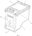
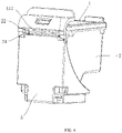
FIG. 1 is a perspective view of an ink cartridge according to an embodiment of the present disclosure. -
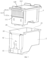
FIG. 2 is an exploded perspective view of an ink cartridge according to an embodiment of the present disclosure. -
FIG. 3 is a perspective view of the ink container inFIG. 1 . -
FIG. 4 is an exploded perspective view of the ink container inFIG. 1 . -
FIG. 5 is an assembly perspective view of the ink container and the print head housing inFIG. 1 . -
FIG. 6 is an assembly perspective view of an ink cartridge according to another embodiment of the present disclosure. -
FIG. 7 is an exploded perspective view of the ink container and the print head housing inFIG. 6 . -
FIG. 8 is an assembly perspective view of the ink container and the print head housing inFIG. 6 . - 1-ink container, 10-ink containing chamber, 11-housing, 110-containing part, 111-side surface, 12-cover body, 120-top surface, 121-ink injecting hole, 122-air guiding hole, 123-air guiding groove, 13-overlay film, 14-pressing part, 15-stopper, 16-rib, 17-engaging part, 18-positioning member, 19-supporting part, 2-print head housing, 20-mounting chamber, 21-limiting groove, 22-first notch, 3-protective cover, 31-second notch, 4-chip component, 41-first chip, 411-first substrate, 411a-first area, 411b-second area, 411c-flexible connection area, 411d-positioning hole, 412-information contact, 42-second chip, 43-third chip.
- The accompanying drawings, which are incorporated in and constitute a part of the specification, illustrate embodiments consistent with the present disclosure, and explain the principles of the present disclosure together with the description.
- In order to better understand the purpose, technical solutions and advantages of the present disclosure, the present disclosure will be further described in detail below with reference to the accompanying drawings and embodiments. It should be understood that the specific embodiments described herein are only used to explain the present disclosure, but not to limit the present disclosure.
- In the description of the present disclosure, unless additional specification and limitation, the terms "first" and "second" are only used for the purpose of description, but not construed as indicating or implying relative importance. Unless otherwise specification or illustration, the term "plurality" refers to two or more. The terms "connection" and "fixed" should be understood in a broad sense. For example, "connection" can be fixed connection, detachable connection, integrated connection, or electrical connection. Also, "connection" can be direct connection, or indirect connection through an intermediate medium. For those skilled in the art, the specific meanings of the above terms in the present disclosure can be understood according to specific situations.
- In the illustration of the description, it should be understood that the directional words such as "top" and "bottom" described in the embodiments of the present disclosure are described from the perspective shown in the accompanying drawings, but should not be construed as limitations to the embodiments of the present disclosure. In addition, it should also be understood that when it is referred that an element is connected "above" or "under" another element in the contexts, the element can not only be directly connected "above" or "under" the other element, but also be indirectly connected "above" or "under" the other element through an intermediate element.
- As shown in
FIGs. 1 and2 , an embodiment of the present disclosure discloses an ink cartridge having a print head, the ink cartridge includes anink container 1, aprint head housing 2, aprotective cover 3, achip component 4 and a print head (not shown in the figures). The print head is provided at the bottom of theprint head housing 2 for printing jobs. Theprint head housing 2 includes a mountingchamber 20. Theink container 1 is detachably installed in the mountingchamber 20. Theink container 1 has anink containing chamber 10, and theink containing chamber 10 is configured to contain ink, so as to provide ink for the print head through theink container 1. Theink container 1 can be taken out from theprint head housing 2 for replacement when the ink in theink container 1 is exhausted. Theprotective cover 3 partially encloses and is fastened to theprint head housing 2 and theink container 1 to protect theprint head housing 2 and theink container 1. Thechip component 4 includes afirst chip 41. Thefirst chip 41 is provided at the outer surface of theink container 1, and at least a part thefirst chip 41 is exposed to the outer surface of the ink cartridge. The part of thefirst chip 41 exposed to the outer surface of the ink cartridge includes aninformation contact 412, and theinformation contact 412 is configured for rewriting, upgrading or recording information. - In the present disclosure, by exposing a part of the
information contact 412 to the outer surface of the ink cartridge, when thefirst chip 41 needs to be upgraded or information-rewritten, it is not required to disassemble theprotective cover 3 or take out theink container 1 from theprint head housing 2, and thefirst chip 41 of theink container 1 can be directly upgraded or information-rewritten, so that the performance of the ink cartridge is improved. - In an embodiment, the
chip component 4 further includes asecond chip 42 and athird chip 43. Thethird chip 43 is provided at the outer wall of theprint head housing 2, and configured to contact with the printing device to realize electrical connection. One end of thesecond chip 42 is provided at the outer wall of theprint head housing 2 and electrically connected to thethird chip 43, and the other end of thesecond chip 42 extends to the inner wall of the mountingchamber 20 and is electrically connected to thefirst chip 41. - As shown in
FIG. 3 , theink container 1 includes aside surface 111 and atop surface 120, thefirst chip 41 further includes afirst substrate 411, one end of thefirst substrate 411 is provided at theside surface 111, and the other end of thefirst substrate 411 extends to thetop surface 120. Theinformation contact 412 is provided at the end of thefirst substrate 411 extending to thetop surface 120. - In an embodiment, the
first substrate 411 includes afirst area 411a, asecond area 411b and aflexible connection area 411c. Thefirst area 411a is provided at theside surface 111 to be electrically connected with thesecond chip 42. Thesecond area 411b is provided at thetop surface 120. Theinformation contact 412 is provided at thesecond area 411b. Theflexible connection area 411c is wound around the junction of theside surface 111 and thetop surface 120. One end of theflexible connection area 411c is electrically connected to thefirst area 411a, and the other end of theflexible connection area 411c is electrically connected to thesecond area 411b. - As shown in
FIG. 4 , thethird chip 43 includes a third substrate, a plurality of electrical contacts and conductive contacts (not shown in the figure). The third substrate is provided at the outer wall of theprint head housing 2. The plurality of electrical contacts and conductive contacts are respectively provided at the outer side of the third substrate. The plurality of electrical contacts are configured to connect with corresponding contacts at the printer side, so as to establish an electrical connection between the third chip and the printer. Thesecond chip 42 includes a second substrate. The second substrate includes a first area and a second area. A contact part is provided at the side of the first area of the second substrate facing thethird chip 43. The first area of thesecond chip 42 can be attached to the outer side of thethird chip 43, so that the contact part of thesecond chip 42 one-to-one corresponds to the conductive contacts of thethird chip 43, so as to achieve electrical connection. The second area of thesecond chip 42 bypasses the edge of the opening of the mountingchamber 20 and extends to the inner wall of the mountingchamber 20, and is in contact with thefirst area 411a of thefirst chip 41 to realize electrical connection. - In this embodiment, the
first area 411a of thefirst chip 41 is made of a rigid plate which can enhance the strength of thefirst chip 41 and make it easier to fix thefirst chip 41 on theink container 1. Thesecond area 411b and theflexible connection area 411c of thefirst chip 41 are both made of flexible plates which are bent over the stopper on theink container 1 and fixed at the top surface of theink container 1. Therefore, after theink container 1 is installed in theprint head housing 2 and theprotective cover 3 is installed, the information contact 412 of thesecond area 411b of thefirst chip 41 can still be exposed to the outer surface of the ink cartridge, so as to facilitate operations of information-rewriting and upgrading. - It can be understood that, in other embodiments, it is possible that the
flexible connection area 411c is made of a flexible plate, and both thefirst area 411a and thesecond area 411b are made of rigid plates. - As shown in
FIGs. 1 and4 , theink container 1 includes ahousing 11, acover body 12, apressing part 14, astopper 15, arib 16 and anengaging part 17. Theink containing chamber 10 is opened at thehousing 11. Thehousing 11 includes aside surface 111. Theside surface 111 includes a containingpart 110. The containingpart 110 is configured to contain a wafer integration part provided at the back surface of thefirst area 411a of thefirst substrate 411. Thepressing part 14 and theengaging part 17 are respectively connected to the side walls of the housing11. Theprint head housing 2 is provided with a limitinggroove 21. The limitinggroove 21 is in cooperation with the engagingpart 17, so that theink container 1 can be engaged and fixed with theprint head housing 2 through the engagingpart 17 and the limitinggroove 21. Thestopper 15 is connected to the upper surface of thecover body 12 and configured to be engaged with the printer body, so that the ink cartridge is installed and fixed in the printer body. Therib 16 is provided at both sides of thehousing 11 and configured to increase friction, engage, snap or cooperate with the inner wall of theprint head housing 2, so as to enhance the stability of the fixation of theink container 1 in theprint head housing 2. Thecover body 12 is connected to thehousing 11 by welding, so that thecover body 12 can cover theink containing chamber 10. - In some embodiments, the number of the
stopper 15 may be one or more. For example, threestoppers 15 are provided, two of which are provided at the same end of the top of thecover body 12 and symmetrically about the axis of thecover body 12, and the other one of which is provided at the other end of the top of thecover body 12 and the center line thereof is collinear with the axis of thecover body 12. The imaging device is provided with slots corresponding to eachstopper 15, respectively. When the ink cartridge is installed into the body of the imaging device, eachstopper 15 extends into a corresponding slot on the body of the imaging device to be engaged. It can be understood that, in other embodiments, one, two or more than threestoppers 15 can be provided, and the specific providing position can also be set according to actual requirements. In that circumstances, the stopper located at the other end of the top of thecover body 12 may also have the function of fixing the protective cover. - Further, the
cover body 12 is provided with anink injecting hole 121, anair guiding hole 122 and anair guiding groove 123. Theink injecting hole 121 is communicated with theink containing chamber 10. The ink can be injected into theink containing chamber 10 through theink injecting hole 121, so that the operation is simple and convenient. Theair guiding hole 122 is communicated with theink containing chamber 10, so as to balance the air pressure between theink containing chamber 10 and the external environment, so that the ink can flow out smoothly. At the same time, by leading out the air in theink containing chamber 10, the ink in theink containing chamber 10 is prevented from drying out due to the evaporation. Alternatively, theair guiding hole 122 may be circular or square, as long as air communication can be achieved. One end of theair guiding groove 123 is connected to theair guiding hole 122, and the other end of theair guiding groove 123 is provided with an opening that communicates with the outside. The numbers ofink injecting holes 121 andair guiding holes 122 are related to the type of ink cartridge. - In order to prevent the outside air from entering through the
air guiding hole 122, causing the ink inside theink containing chamber 10 to evaporate and get dried, and also to prevent the ink from flowing out through theair guiding hole 122 and theink injecting hole 121, theink container 1 further includes anoverlay film 13. Theoverlay film 13 is overlaid over theair guiding groove 123, theair guiding hole 122 and theink injecting hole 121. In some embodiments, theoverlay film 13 may be an aluminum plate or a plastic film. For example, theoverlay film 13 is made of a transparent PVC material, and the ink in theink containing chamber 10 can be observed through theair guiding hole 122. When there is air inside theink containing chamber 10, since the density of the air is lower than the ink, the air is above theink containing chamber 10, flows into theair guiding hole 122, then enters one port of theair guiding groove 123, flows along theair guiding groove 123, reaches the other port ofair guiding groove 123, and finally flow out from the opening and into the external air. - In this embodiment, since the
overlay film 13 covers theair guiding hole 122, theair guiding hole 122 cannot be used to balance the air pressure between theink containing chamber 10 and the external environment, so that a pressure difference exists between theink containing chamber 10 and the outside, which may cause the ink injection difficult. Therefore, the other port of theair guiding groove 123 is provided with an opening. The opening is communicated to the external air, and is configured to balance the air pressure between theink containing chamber 10 and the external environment, making the ink injection easy and smooth. Theair guiding groove 123 may be a straight pipe segment, and is configured to exhaust the air inside theink containing chamber 10. In an embodiment, theair guiding groove 123 bends and extends at thecover body 12 , and forms a tortuous curve, so as to prevent the ink from flowing out along theair guiding hole 122 and theair guiding groove 123 . - In this embodiment, the
second area 411b of thefirst chip 41 is fixed on one end of thecover body 12, and thereby can also cover a part of theair guiding hole 122, theair guiding groove 123 and theink injecting hole 121. In an embodiment, in order to optimize the sealing quality, theoverlay film 13 is used to cover theair guiding hole 122, the guidinggroove 123 and the injectinghole 121 throughout thecover body 12, and then thesecond area 411 of thefirst chip 41 is welded or pasted to theoverlay film 13, the fixation means is not limited herein. - In this embodiment, the interior of the
ink containing chamber 10 is divided into three compartments by partition plates, which store the ink of three colors C, M, and Y, respectively. Sponge or other porous materials can be arranged in the three storage chambers, and is used to absorb and store ink. The upper openings of the three storage chambers correspond to theair guiding hole 122, theair guiding groove 123 and theink injecting hole 121, respectively. The correspondingair guiding groove 123 extends to the rear end of thecover body 12 through a tortuous maze channel and aggregates therein. When only the ink of BK color is stored in theink container 1, the number and layout of theair guiding holes 122, theair guiding groove 123 and theink injecting holes 121 on thecorresponding cover body 12 will also be changed accordingly, which will not be described here. - Since the
ink container 1 is often placed on the table when replacing theink container 1, the dust on the table will easily enter theink container 1 from the ink outlet (located at the bottom, not shown) of theink container 1 and lead to contaminating the ink in theink container 1. In order to prevent the ink in theink container 1 from being contaminated, theink container 1 further includes a supportingpart 19. The supportingpart 19 is provided at one side of the bottom of thehousing 11, and the length of the supportingpart 19 protruding from the bottom of thehousing 11 is greater than the ink outlet protruding from the bottom of the housing. Through the setting of the supportingpart 19, the ink outlet of theink container 1 can be prevented from directly contacting the outside, and dust can be prevented from entering the ink outlet. - As shown in
FIG. 5 , theink container 1 further includes a positioningmember 18. The positioningmember 18 is connected to theside surface 111 of thehousing 11. Thefirst substrate 411 is provided with apositioning hole 411d. The position of thepositioning hole 411d corresponds to the position of the positioningmember 18. When thefirst chip 41 is connected to theink container 1, guidance is realized by thepositioning hole 411d and the positioningmember 18, so that thefirst chip 41 can be connected to theink container 1 more smoothly. Further, thefirst area 411a of thefirst chip 41 can be fixed to the surface of theink container 1 by a process such as welding or pasting. Alternatively, the ends of the positioningmember 18 can be softened by heating, so that the ends of the positioningmember 18 can bend to cover at least a part of thefirst substrate 411. As the positioningmember 18 is cooled and solidified, the positioningmember 18 can cover the surface of thefirst substrate 411 like a flange to fix thefirst area 411a of thefirst substrate 411. - On the basis of the above-mentioned embodiments, the present disclosure further provides another embodiment. As shown in
FIGs. 6 to 8 , this embodiment differs from the above-mentioned embodiments in that, thefirst substrate 411 is only provided at theside surface 111 of theink container 1, and does not extend to thetop surface 120 of the ink container1. Theinformation contact 412 is provided at thefirst substrate 411, that is, theinformation contact 412 is only located at theside surface 111 of theink container 1. Theprint head housing 2 is provided with afirst notch 22. The position of thefirst notch 22 corresponds to the position of theinformation contact 412. Theprotective cover 3 is provided with asecond notch 31. The position of thesecond notch 31 corresponds to the position of thefirst notch 22, so that theinformation contact 412 is exposed to the outer surface of the ink cartridge. When thefirst chip 41 needs to be upgraded or information-rewritten, thefirst chip 41 can be directly upgraded or information rewritten through thesecond notch 31 and thefirst notch 22. - The
first substrate 411 includes afirst area 411a and asecond area 411b electrically connected to thefirst area 411a. Thefirst area 411a is configured to contact with thesecond chip 42 to realize electrical connection. Thesecond area 411b is exposed to the outer surface of the ink cartridge. Theinformation contact 412 is provided at thesecond area 411b to facilitate operations such as information-rewriting or upgrading. - Further, the
second area 411b is located at the end of thefirst substrate 411 adjacent to thetop surface 120 of the ink cartridge. Thefirst notch 22 penetrates through the opening of the mountingchamber 20. One end of thesecond chip 42 is provided at the outer wall of thehousing 11, and the other end of thesecond chip 42 bypasses thefirst notch 22 and extends to the inner wall of the mountingchamber 20 and contacts with thefirst area 411a to realize electrical connection. - In this embodiment, the structure of the first chip is simplified, so that the first chip does not need to be additionally provided with an area wound around the top surface, so that the process is simplified, and the cost of the first chip is reduced. It is only necessary to add a row of contacts on the substrate of the first chip, and provide corresponding notches on the print head housing and the protective cover to simplify the operation process of chip-rewriting or upgrading.
- The above descriptions are only preferred specific embodiments of the present disclosure, but not limitation to the protection scope of the present disclosure. Any change or substitution which can be easily envisaged by those skilled in the art within the technical scope disclosed in the present disclosure should be covered within the scope of protection of the present disclosure. Therefore, the protection scope of the present disclosure should be subject to the protection scope of the claims.
Claims (10)
- An ink cartridge having a print head, comprising:an ink container having an ink containing chamber for containing ink;a print head housing having a mounting chamber, wherein the ink container is mounted in the mounting chamber and is configured to supply ink to a print head mounted on the print head housing; anda first chip provided at an outer surface of the ink container, wherein at least a part of the first chip is exposed to an outer surface of the ink cartridge, and the part of the first chip exposed to the outer surface of the ink cartridge comprises an information contact.
- The ink cartridge according to claim 1, wherein the ink container comprises a side surface and a top surface, the first chip further comprises a first substrate, one end of the first substrate is provided at the side surface, and the other end of the first substrate extends to the top surface; and the information contact is provided at the end of the first substrate extending to the top surface.
- The ink cartridge according to claim 2, wherein the first substrate comprises a first area, a second area and a flexible connection area, the first area is provided at the side surface, the second area is provided at the top surface, and the flexible connection area is wound around a junction of the side surface and the top surface, one end of the flexible connection area is connected to the first area, the other end of the flexible connection area is connected to the second area, and the information contact is provided in the second area.
- The ink cartridge according to claim 1, wherein the ink cartridge further comprises a protective cover, and the protective cover partially encloses and is fastened to the print head housing and the ink container.
- The ink cartridge according to claim 1, wherein the ink container comprises a side surface, the first chip further comprises a first substrate, the first substrate is provided at the side surface, the information contact is provided at the first substrate, the print head housing is provided with a first notch, and a position of the first notch corresponds to a position of the information contact.
- The ink cartridge according to claim 5, wherein the first substrate comprises a second area, the second area is provided at an end of the first substrate adjacent to a top surface of the ink container, and the information contact is provided in the second area.
- The ink cartridge according to claim 6, wherein the first notch penetrates through an opening of the mounting chamber.
- The ink cartridge according to claim 5, wherein the ink cartridge further comprises a protective cover, the protective cover partially encloses and is fastened to the print head housing and the ink container, the protective cover is provided with a second notch, and a position of the second notch corresponds to the position of the first notch.
- The ink cartridge according to claim 1, wherein the ink container comprises a positioning member, the first substrate is provided with a positioning hole, and the positioning hole is provided corresponding to the positioning member.
- The ink cartridge according to any one of claims 1 to 9, wherein the chip component further comprises a second chip and a third chip, the third chip is provided at an outer wall of the print head housing, and one end of the second chip is provided at the outer wall of the print head housing and electrically connected with the third chip, and the other end of the second chip extends to an inner wall of the mounting chamber and is electrically connected to the first chip.
Applications Claiming Priority (2)
| Application Number | Priority Date | Filing Date | Title |
|---|---|---|---|
| CN202021995427.7U CN214215199U (en) | 2020-09-11 | 2020-09-11 | Ink cartridge with printhead |
| PCT/CN2021/091594 WO2022052488A1 (en) | 2020-09-11 | 2021-04-30 | Ink cartridge having print head |
Publications (2)
| Publication Number | Publication Date |
|---|---|
| EP4140748A1 true EP4140748A1 (en) | 2023-03-01 |
| EP4140748A4 EP4140748A4 (en) | 2024-04-24 |
Family
ID=77674219
Family Applications (1)
| Application Number | Title | Priority Date | Filing Date |
|---|---|---|---|
| EP21865549.6A Pending EP4140748A4 (en) | 2020-09-11 | 2021-04-30 | Ink cartridge having print head |
Country Status (5)
| Country | Link |
|---|---|
| US (1) | US12304212B2 (en) |
| EP (1) | EP4140748A4 (en) |
| JP (1) | JP7432265B2 (en) |
| CN (1) | CN214215199U (en) |
| WO (1) | WO2022052488A1 (en) |
Cited By (1)
| Publication number | Priority date | Publication date | Assignee | Title |
|---|---|---|---|---|
| WO2025095946A1 (en) * | 2023-10-31 | 2025-05-08 | Hewlett-Packard Development Company, L.P. | Fluid cartridge with retention member |
Families Citing this family (2)
| Publication number | Priority date | Publication date | Assignee | Title |
|---|---|---|---|---|
| CN117048209A (en) * | 2023-09-15 | 2023-11-14 | 珠海纳思达企业管理有限公司 | Lead cartridge |
| CN119388883B (en) * | 2024-12-31 | 2025-03-28 | 极海微电子股份有限公司 | First chip, communication method, chip assembly and replaceable accessories |
Family Cites Families (19)
| Publication number | Priority date | Publication date | Assignee | Title |
|---|---|---|---|---|
| EP0335699B1 (en) | 1988-03-31 | 1995-06-14 | Canon Kabushiki Kaisha | Replaceable ink jet cartridge and ink jet apparatus having the same |
| JPH0760953A (en) | 1993-08-26 | 1995-03-07 | Canon Inc | INKJET RECORDING HEAD AND RECORDING DEVICE HAVING THE RECORDING HEAD |
| JPH08216397A (en) * | 1995-02-20 | 1996-08-27 | Matsushita Electric Ind Co Ltd | Ink jet recording device |
| FR2773248B1 (en) * | 1997-12-30 | 2000-03-17 | Neopost Ind | SECURE DIGITAL POSTAL PRINTING MODULE |
| JPH11334052A (en) * | 1998-05-28 | 1999-12-07 | Matsushita Electric Ind Co Ltd | Inkjet printer |
| EP0999060B1 (en) * | 1998-10-27 | 2005-04-20 | Canon Kabushiki Kaisha | Head holder, head assembly, head cartridge, ink jet recorder, and method for manufacturing head assembly |
| GB9925637D0 (en) * | 1999-10-29 | 1999-12-29 | Neopost Ltd | Housing for digital print head |
| JP2003182070A (en) | 2001-12-17 | 2003-07-03 | Ricoh Co Ltd | Droplet discharge head and manufacturing method thereof, ink cartridge, ink jet recording apparatus, microactuator, micropump, optical device |
| JP2004358793A (en) * | 2003-06-04 | 2004-12-24 | Seiko Epson Corp | Ink cartridge remaining amount detection method, ink cartridge remaining amount detection system, ink jet printer, and ink cartridge |
| JP3991041B2 (en) | 2004-06-04 | 2007-10-17 | キヤノン株式会社 | Recording head unit and ink jet recording apparatus |
| JP2008284884A (en) | 2008-09-01 | 2008-11-27 | Canon Inc | Ink tank and inkjet cartridge |
| JP5627312B2 (en) | 2010-06-21 | 2014-11-19 | キヤノン株式会社 | Liquid discharge head and method of assembling liquid discharge head |
| US8544988B1 (en) | 2012-09-05 | 2013-10-01 | Clover Technology Groups, LLC | Recyclable and remanufacturable microprocessor-based postal evidencing module and method of recycling and remanufacturing |
| CN103921558B (en) * | 2013-01-15 | 2016-02-17 | 研能科技股份有限公司 | Separate Print Cartridges |
| EP3403830B1 (en) * | 2013-02-12 | 2019-11-06 | Clover Technologies Group, LLC | Electronic patch for refurbishing a used print cartridge |
| JP6198578B2 (en) | 2013-11-13 | 2017-09-20 | キヤノン株式会社 | Liquid discharge head and manufacturing method thereof |
| US9308737B1 (en) | 2014-10-16 | 2016-04-12 | Funai Electric Co., Ltd. | Agitating member for ink cartridge |
| JP2016107525A (en) | 2014-12-08 | 2016-06-20 | セイコーエプソン株式会社 | Protection member and set of liquid supply unit |
| US9873250B2 (en) | 2016-03-14 | 2018-01-23 | Stmicroelectronics, Inc. | Microfluidic assembly with mechanical bonds |
-
2020
- 2020-09-11 CN CN202021995427.7U patent/CN214215199U/en active Active
-
2021
- 2021-04-30 WO PCT/CN2021/091594 patent/WO2022052488A1/en not_active Ceased
- 2021-04-30 JP JP2022571263A patent/JP7432265B2/en active Active
- 2021-04-30 US US18/001,239 patent/US12304212B2/en active Active
- 2021-04-30 EP EP21865549.6A patent/EP4140748A4/en active Pending
Cited By (1)
| Publication number | Priority date | Publication date | Assignee | Title |
|---|---|---|---|---|
| WO2025095946A1 (en) * | 2023-10-31 | 2025-05-08 | Hewlett-Packard Development Company, L.P. | Fluid cartridge with retention member |
Also Published As
| Publication number | Publication date |
|---|---|
| JP2023529572A (en) | 2023-07-11 |
| EP4140748A4 (en) | 2024-04-24 |
| US20230226822A1 (en) | 2023-07-20 |
| WO2022052488A1 (en) | 2022-03-17 |
| CN214215199U (en) | 2021-09-17 |
| JP7432265B2 (en) | 2024-02-16 |
| US12304212B2 (en) | 2025-05-20 |
Similar Documents
| Publication | Publication Date | Title |
|---|---|---|
| US12304212B2 (en) | Ink cartridge having print head | |
| EP2886349B1 (en) | Liquid supply unit | |
| US7445323B2 (en) | Ink cartridge venting | |
| US8172386B2 (en) | Sealing device for fluid reservoir | |
| ITTO960188A1 (en) | CONTAINMENT CASE FOR AN INKJET PRINTING UNIT | |
| BRPI0407975B1 (en) | INK CARTRIDGES, VALVE DEVICE, INK JET RECORDING EQUIPMENT AND INK SUPPLY METHOD | |
| US8684505B2 (en) | Vent path for a liquid container | |
| BR112016015309A2 (en) | ? LIQUID SUPPLY UNIT? | |
| EP2930028B1 (en) | Protection member for liquid supply unit | |
| CN111016441B (en) | Ink cartridge device | |
| RU129875U1 (en) | RECORDING DEVICE | |
| CN112277475B (en) | ink cartridge | |
| CN212022025U (en) | Ink box | |
| US9475297B2 (en) | Vent through a printhead support structure | |
| CN214395987U (en) | Ink box upgrading packaging assembly | |
| US7175267B2 (en) | Ink cartridge | |
| US9849681B2 (en) | Structure for printhead having multiple air channels | |
| US7837312B2 (en) | Liquid cartridge and method for manufacturing the same | |
| US20060274129A1 (en) | Ink supply system for ink cartridge | |
| CN212242646U (en) | Ink box | |
| US12358297B2 (en) | Printer | |
| CN110962459B (en) | Liquid ejecting apparatus | |
| JP2000190522A (en) | Ink cartridge for inkjet printer | |
| JP2000025244A (en) | Ink refill cartridge | |
| US20050088496A1 (en) | Ink refilling cap |
Legal Events
| Date | Code | Title | Description |
|---|---|---|---|
| STAA | Information on the status of an ep patent application or granted ep patent |
Free format text: STATUS: THE INTERNATIONAL PUBLICATION HAS BEEN MADE |
|
| PUAI | Public reference made under article 153(3) epc to a published international application that has entered the european phase |
Free format text: ORIGINAL CODE: 0009012 |
|
| STAA | Information on the status of an ep patent application or granted ep patent |
Free format text: STATUS: REQUEST FOR EXAMINATION WAS MADE |
|
| 17P | Request for examination filed |
Effective date: 20221123 |
|
| AK | Designated contracting states |
Kind code of ref document: A1 Designated state(s): AL AT BE BG CH CY CZ DE DK EE ES FI FR GB GR HR HU IE IS IT LI LT LU LV MC MK MT NL NO PL PT RO RS SE SI SK SM TR |
|
| DAV | Request for validation of the european patent (deleted) | ||
| DAX | Request for extension of the european patent (deleted) | ||
| A4 | Supplementary search report drawn up and despatched |
Effective date: 20240321 |
|
| RIC1 | Information provided on ipc code assigned before grant |
Ipc: B41J 2/14 20060101ALI20240315BHEP Ipc: B41J 2/175 20060101AFI20240315BHEP |
|
| STAA | Information on the status of an ep patent application or granted ep patent |
Free format text: STATUS: EXAMINATION IS IN PROGRESS |
|
| 17Q | First examination report despatched |
Effective date: 20250813 |