EP4140625A1 - Portable helical milling unit and eccentricity adjustment method - Google Patents
Portable helical milling unit and eccentricity adjustment method Download PDFInfo
- Publication number
- EP4140625A1 EP4140625A1 EP20932386.4A EP20932386A EP4140625A1 EP 4140625 A1 EP4140625 A1 EP 4140625A1 EP 20932386 A EP20932386 A EP 20932386A EP 4140625 A1 EP4140625 A1 EP 4140625A1
- Authority
- EP
- European Patent Office
- Prior art keywords
- eccentricity
- outer sleeve
- spindle
- eccentric
- sleeve
- Prior art date
- Legal status (The legal status is an assumption and is not a legal conclusion. Google has not performed a legal analysis and makes no representation as to the accuracy of the status listed.)
- Pending
Links
Images




Classifications
-
- B—PERFORMING OPERATIONS; TRANSPORTING
- B23—MACHINE TOOLS; METAL-WORKING NOT OTHERWISE PROVIDED FOR
- B23C—MILLING
- B23C9/00—Details or accessories so far as specially adapted to milling machines or cutter
- B23C9/005—Details or accessories so far as specially adapted to milling machines or cutter milling heads
-
- B—PERFORMING OPERATIONS; TRANSPORTING
- B23—MACHINE TOOLS; METAL-WORKING NOT OTHERWISE PROVIDED FOR
- B23C—MILLING
- B23C3/00—Milling particular work; Special milling operations; Machines therefor
- B23C3/02—Milling surfaces of revolution
-
- B—PERFORMING OPERATIONS; TRANSPORTING
- B23—MACHINE TOOLS; METAL-WORKING NOT OTHERWISE PROVIDED FOR
- B23C—MILLING
- B23C1/00—Milling machines not designed for particular work or special operations
- B23C1/06—Milling machines not designed for particular work or special operations with one vertical working-spindle
-
- B—PERFORMING OPERATIONS; TRANSPORTING
- B23—MACHINE TOOLS; METAL-WORKING NOT OTHERWISE PROVIDED FOR
- B23C—MILLING
- B23C1/00—Milling machines not designed for particular work or special operations
- B23C1/20—Portable devices or machines; Hand-driven devices or machines
-
- B—PERFORMING OPERATIONS; TRANSPORTING
- B23—MACHINE TOOLS; METAL-WORKING NOT OTHERWISE PROVIDED FOR
- B23C—MILLING
- B23C2215/00—Details of workpieces
- B23C2215/04—Aircraft components
-
- B—PERFORMING OPERATIONS; TRANSPORTING
- B23—MACHINE TOOLS; METAL-WORKING NOT OTHERWISE PROVIDED FOR
- B23C—MILLING
- B23C2220/00—Details of milling processes
- B23C2220/52—Orbital drilling, i.e. use of a milling cutter moved in a spiral path to produce a hole
-
- B—PERFORMING OPERATIONS; TRANSPORTING
- B23—MACHINE TOOLS; METAL-WORKING NOT OTHERWISE PROVIDED FOR
- B23C—MILLING
- B23C2260/00—Details of constructional elements
- B23C2260/04—Adjustable elements
-
- B—PERFORMING OPERATIONS; TRANSPORTING
- B23—MACHINE TOOLS; METAL-WORKING NOT OTHERWISE PROVIDED FOR
- B23C—MILLING
- B23C2260/00—Details of constructional elements
- B23C2260/08—Bearings
-
- B—PERFORMING OPERATIONS; TRANSPORTING
- B23—MACHINE TOOLS; METAL-WORKING NOT OTHERWISE PROVIDED FOR
- B23C—MILLING
- B23C2260/00—Details of constructional elements
- B23C2260/68—Rings
-
- B—PERFORMING OPERATIONS; TRANSPORTING
- B23—MACHINE TOOLS; METAL-WORKING NOT OTHERWISE PROVIDED FOR
- B23C—MILLING
- B23C2260/00—Details of constructional elements
- B23C2260/76—Sensors
-
- B—PERFORMING OPERATIONS; TRANSPORTING
- B23—MACHINE TOOLS; METAL-WORKING NOT OTHERWISE PROVIDED FOR
- B23C—MILLING
- B23C2265/00—Details of general geometric configurations
- B23C2265/12—Eccentric
Definitions
- the present disclosure relates to the technical field of hole machining in assembly of aerospace vehicles, in particular to a portable helical milling unit and an eccentric adjustment method.
- Difficult-to-machine materials including composite materials, aluminum alloys, titanium alloys and high-strength steel, as well as different forms of laminated structures composed of at least two materials, are widely used in aerospace vehicles.
- Anew hole machining method is to use a special end mill for helical milling, with a principle that the tool rotates on it axis at a high speed while feeds along the helical path, so that a circular hole with a diameter larger than the tool is machined on the workpiece.
- helical milling is superior to traditional drilling.
- Helical milling is applied to aircraft assembly instead of traditional drilling to machine some holes with high quality requirements, such as bolt holes and rivet holes.
- the application scope of helical milling is expanding. The tool needs to feed along the helical path during helical milling whereas the existing hole machining device usually does not have this function. Therefore, it is necessary to develop a special helical milling equipment.
- the current helical milling device there are some problems of the current helical milling device: (1) the overall size of the helical milling device is large and heavy, which is not suitable for helical milling under complex space conditions; (2) the helical milling device has complex structure and high cost, which is not suitable for batch manufacturing; (3) the main processing object of the existing helical milling device is small aperture (with a diameter of no more than 20mm) without pre-hole; for the reaming process of the large-diameter intersection hole (with a maximum diameter of more than 28mm) with pre-hole, the processing equipment needs to have greater power and structural stiffness, which increases the design difficulty.
- the processing aperture of helical milling not only depends on the diameter of the tool, but also directly relates to the eccentricity of the tool.
- the processing aperture of the helical milling is equal to the diameter plus twice the eccentricity of the tool.
- the existing helical milling device usually adopts a dual eccentric sleeve to adjust the eccentricity, and the eccentricities of the inner and outer sleeves cannot be changed.
- the eccentricity adjustment range has been determined after the device is manufactured. However, regardless of the eccentricity adjustment range, the eccentricity of the tool is changed by changing the relative rotational angle between the inner and outer sleeves during operation, and the eccentricity is changed from the minimum value to the maximum value during the relative rotation by 180 degrees between the inner and outer sleeves.
- the eccentricity adjustment range When the eccentricity adjustment range is large, the eccentricity will change greatly if the inner and outer sleeves relatively rotate a small angle. It is difficult to realize a micro eccentricity adjustment so as to affect the eccentricity adjustment accuracy.
- the eccentricity adjustment range When the eccentricity adjustment range is small, it is necessary to relatively rotate the inner and outer sleeves a larger angle to change the eccentricity by the same value, which makes it easier to realize the micro eccentricity adjustment and improve the eccentricity adjustment accuracy.
- the aperture range processed by the helical milling device is also reduced accordingly. Therefore, for the eccentricity adjustment method of the existing helical milling device, it is contradictory to improve the eccentricity adjustment accuracy and increase the adjustment range, and it is difficult to achieve both at the same time.
- the main difficulties of the eccentricity adjustment of the existing helical milling device include that: (1) inaccurate adjustment of eccentricity will result to unqualified machining aperture. In order to process a qualified hole, the helical milling device should adjust the eccentricity to a small enough error with the theoretical value through the eccentricity adjustment mechanism to ensure that the actual machining aperture is qualified. (2) If the variation range of the machining aperture is large, it is necessary to ensure that the eccentricity adjustment range is large enough. Otherwise, during the machining process, tools with different diameters need to be replaced to meet the machining requirements of different apertures, which reduces the machining efficiency and increases the cost. Therefore, the design difficulty of the helical milling device is to ensure that the eccentricity has a large enough adjustment range and a high enough adjustment accuracy.
- a portable helical milling unit includes a tool, an eccentric spindle, an outer sleeve, a sleeve housing, and a plurality of transmission mechanisms for providing power.
- the eccentric spindle is detachably sleeved in an inner hole of output section of the outer sleeve.
- Each of the eccentric spindle and the outer sleeve has a pre-set eccentricity.
- the tool is in connection with the output side of the eccentric spindle.
- the eccentric spindle is detachably connected in the outer sleeve.
- the outer sleeve is installed in the sleeve housing through a sliding bearing.
- An input side of the outer sleeve is in connection with a first transmission mechanism and a third transmission mechanism, and an input side of the eccentric spindle is in connection with a second transmission mechanism.
- the third transmission mechanism is used to drive the outer sleeve to rotate relative to the outer sleeve housing to enable the tool to rotate around an axis of the outer cylindrical surface of the outer sleeve.
- the first transmission mechanism is used to drive the outer sleeve to move back and forth relative to an axis direction of the sleeve housing to achieve the feed motion of the tool.
- the second transmission mechanism is used to drive the eccentric spindle to rotate so as to rotate the tool.
- the output section of the outer sleeve is an eccentric structure, that is, the axis of the outer cylindrical surface of the outer sleeve has a certain eccentricity e 0 with the axis of the inner hole of the output section of the outer sleeve.
- the middle section and the input section of the outer sleeve are concentric, that is, the axis of the outer cylindrical surface of the outer sleeve is concentric with the axes of the inner holes of the middle section and the input section of the outer sleeve.
- the eccentric spindle includes a spindle and an inner sleeve having an eccentric structure, that is, the axis of the outer cylindrical surface of the eccentric spindle has a certain eccentricity e n with the axis of the inner hole of the output section of the outer sleeve, and the spindle is sleeved in the inner hole of the inner sleeve through a spindle bearing.
- the output section of the outer sleeve is an eccentric structure, that is, the axis of the outer cylindrical surface of the outer sleeve has a certain eccentricity e 0 with the axis of the inner hole of the output section of the outer sleeve.
- the middle section and the input section of the outer sleeve are concentric, that is, the axis of the outer cylindrical surface of the outer sleeve is concentric with the axes of the inner holes of the middle section and the input section of the outer sleeve.
- the eccentric spindle includes a tool, an inner sleeve, a spindle and an eccentricity adjustment mechanism.
- the eccentricity adjustment mechanism includes a gear transmission shaft, a rotating shaft, a first gear, a second gear, and a third gear.
- the inner sleeve is a concentric structure, and the spindle is sleeved in the inner hole of the inner sleeve through a spindle bearing.
- the output end of the spindle is installed with the first gear which is meshed with the third gear for transmission.
- the third gear is installed on the gear transmission shaft and meshed with the second gear for transmission.
- the second gear is installed at the input end of the rotating shaft.
- the rotating shaft is installed on the inner sleeve through a bearing, and the tool is installed at a front end of the rotating shaft.
- a distance between axes of the first gear and the second gear is e n .
- the second transmission mechanism includes a second motor and a transmission shaft.
- the output end of the second motor is in connection with the input end of the transmission shaft, and the output end of the transmission shaft is in connection with the input end of the spindle.
- the third transmission mechanism includes a third motor and a first synchronous cog belt, the input end of the outer sleeve is installed with a third synchronous cog belt wheel.
- the third synchronous cog belt wheel is in connection with a fourth synchronous cog belt wheel installed at the output end of the third motor through the first synchronous cog belt.
- the outer side of the input section of the outer sleeve is in connection with the translational plate through a revolution bearing.
- the second transmission mechanism further includes an encoder for measuring a rotational speed of the spindle.
- the encoder is installed at the output end of the second motor or the output end of the transmission shaft.
- the housing of the encoder is fixed on the translational plate through an encoder support base.
- the transmission shaft is installed at the input section of the outer sleeve through a transmission bearing.
- a circular shaft of the output end of the transmission shaft is in connection with the input end of a universal joint coupling through a key joint, and the output end of the universal joint coupling is in connection with the input end of the spindle.
- an outer side of the output end of the sleeve housing is fixed to the sleeve housing through a flange, and both sides of the sleeve housing are installed with handles.
- the universal joint coupling is a double cross-shaft universal joint coupling.
- a number of teeth of the first gear is represented as Z1
- a number of teeth of the second gear is represented as Z2
- a rotational speed of the spindle is represented as n1
- determining the ranges of the eccentricity e 0 of the outer sleeve and the eccentricity e n of the eccentric spindle in step S1 includes the following steps of:
- the present disclosure can be widely popularized in the field of hole machining technology.
- the present disclosure provides a portable helical milling unit including a tool 2, an eccentric spindle 1, an outer sleeve 12, a sleeve housing 14, and a plurality of transmission mechanisms for providing power.
- the eccentric spindle 1 is detachably sleeved in an inner hole of output section of the outer sleeve 12.
- Each of the eccentric spindle 1 and the outer sleeve 12 has a pre-set eccentricity.
- the tool 2 is in connection with the output side of the eccentric spindle 1.
- the eccentric spindle 1 is detachably connected in the outer sleeve 12.
- the outer sleeve 12 is installed in the sleeve housing 14 through a sliding bearing 13.
- An input side of the outer sleeve 12 is in connection with a first transmission mechanism and a third transmission mechanism, and an input side of the eccentric spindle 1 is in connection with a second transmission mechanism.
- the third transmission mechanism is used to drive the outer sleeve 12 to rotate relative to the outer sleeve housing 14 to enable the tool 2 to rotate around the axis of the outer cylindrical surface of the outer sleeve 12.
- the first transmission mechanism is used to drive the outer sleeve 12 to move back and forth relative to the axis direction of the sleeve housing 14 to achieve the feed motion of the tool 2.
- the second transmission mechanism is used to drive the eccentric spindle 1 to rotate so as to rotate the tool 2.
- the output section of the outer sleeve 12 is an eccentric structure, i.e., the axis of the outer cylindrical surface of the outer sleeve has a certain eccentricity e 0 with the axis of the inner hole of the output section of the outer sleeve 14.
- the middle section and the input section of the outer sleeve are concentric, i.e., the axis of the outer cylindrical surface of the outer sleeve is concentric with the axes of the inner holes of the middle section and the input section of the outer sleeve 12.
- the structure of the eccentric spindle 1 has three solutions as follows:
- solution M1 as shown in FIG. 1 and FIG. 2
- the eccentric spindle 1 when the processing object is a hole having a smaller diameter, the eccentric spindle 1 includes a spindle 5 and an inner sleeve 9 having an eccentric structure, that is, the axis of the outer cylindrical surface of the eccentric spindle 1 has a certain eccentricity e n with the axis of the inner hole, and the spindle 5 is sleeved in the inner hole of the inner sleeve 9 through a spindle bearing 10.
- the tool 2 is installed at the front end of the spindle 5.
- the eccentric spindle 1 when the processing object is a hole having a lager diameter, the eccentric spindle 1 includes a spindle 5, an inner sleeve 9 and an eccentricity adjustment mechanism.
- the eccentricity adjustment mechanism includes a gear transmission shaft 4, a rotating shaft 3, a first gear 6 and a second gear 7.
- the inner sleeve 9 is a concentric structure, and the spindle 5 is sleeved in the inner hole of the inner sleeve 9 through a spindle bearing 10.
- the output end of the spindle 5 is installed with the first gear 6 which is meshed with the second gear 7 for transmission.
- the second gear 7 is installed at the input end of the rotating shaft 3 which is installed on the inner sleeve 9 through a bearing 11, and the tool 2 is installed at a front end of the rotating shaft 3.
- a distance between axes of the first gear 6 and the second gear 7 is e n .
- the eccentric spindle 1 when the processing object is a hole having a lager diameter, the eccentric spindle 1 includes an inner sleeve 9, a spindle 5 and an eccentricity adjustment mechanism.
- the eccentricity adjustment mechanism includes a gear transmission shaft 4, a rotating shaft 3, a first gear 6, a second gear 7 and a third gear 8.
- the inner sleeve 9 is a concentric structure, and the spindle 5 is sleeved in the inner hole of the inner sleeve 9 through a spindle bearing 10.
- the output end of the spindle 5 is installed with the first gear 6 which is meshed with the third gear 8 for transmission.
- the third gear 8 is installed on the gear transmission shaft 4 and meshed with the second gear 7 for transmission.
- the first transmission mechanism includes a first motor 15 and a lead screw 18.
- the first motor 15 is horizontally installed on the sleeve housing 14.
- the output end of the first motor 15 is in connection with the lead screw 18 through a lead screw coupling 16.
- One end of the lead screw 18 is installed in a mounting hole of a lead screw support base 17, and the other end is sleeved in a lead screw nut 22.
- the lead screw support base 17 is horizontally installed on the sleeve housing 14, and the lead screw nut 22 is installed on a translational plate 20.
- the second transmission mechanism includes a second motor 19 and a transmission shaft 28.
- the output end of the second motor 19 is in connection with the input end of the transmission shaft 28, and the output end of the transmission shaft 28 is in connection with the input end of the spindle 5.
- the outer side of the input section of the outer sleeve 12 is in connection with the translational plate 20 through a revolution bearing 30.
- the second motor 19 and the third motor 32 are installed on the translational plate 20.
- the input end of the transmission shaft 28 is installed with the second synchronous cog belt wheel 25 which is in connection with the first synchronous cog belt wheel 24 installed on the output end of the second motor 19 through the second synchronous cog belt.
- the second transmission mechanism further includes an encoder 23 for measuring a rotational speed of the spindle 5.
- the encoder 23 is installed at the output end of the second motor 19 or the output end of the transmission shaft 28.
- the housing of the encoder 23 is fixed on the translational plate 20 through an encoder support base 21.
- the axis of the spindle 5 has a certain eccentricity e with the axis of the outer cylindrical surface of the outer sleeve 12, and the axis of the transmission shaft 28 is concentric with the axis of the outer cylindrical surface of the outer sleeve 12. Therefore, the universal joint coupling 35 can realize the transmission between the spindle 5 with a larger eccentricity and the transmission shaft 28.
- An outer side of the output end of the sleeve housing 14 is fixed to the housing 36 through a flange, and both sides of the housing are installed with handles 34.
- the front side of the flange is fixed with a positioning shaft sleeve 38.
- the working principle of the revolution motion of the portable helical milling unit is as follows: the third motor 32 drives the outer sleeve 12 to rotate relative to the sleeve housing 14 and the translational plate 20 by the synchronous cog belt wheel and the cog belt, so as to drive the inner sleeve 9 to rotate; when the outer sleeve 12 and the inner sleeve 9 are relatively stationary, the eccentricity e of the tool 2 relative to the outer cylindrical surface of the outer sleeve 12 keeps constant to realize the revolution motion of the tool 2.
- the working principle of the feed motion of the portable helical milling unit is as follows: the first motor 15 drives the translational plate 20 to move along the axis direction through the lead screw 18 so as to drive the outer sleeve 12 to move along the axis direction relative to the sleeve housing 14 to realize the axial feed motion of the tool 2.
- the position of the axis of the transmission shaft 28 remains unchanged when the third motor 32 drives the outer sleeve 12 to rotate, which is convenient for the second motor 19 to transmit power to the transmission shaft 28 through the synchronous cog belt wheel.
- the working principle of the rotation of the spindle 5 of the portable helical milling unit is as follows: As for the solution M1, the second motor 19 drives the transmission shaft 28 to rotate through the synchronous cog belt wheel and the cog belt, and the transmission shaft 28 concentric with the outer cylindrical surface of the outer sleeve 12 transmits power to the spindle 5 eccentric with the outer cylindrical surface of the outer sleeve 12 through the universal joint coupling 35, so as to drive the spindle 5 to rotate to realize the rotation of the tool 2.
- the encoder 23 detects the real-time rotational speed of the tool 2.
- the second motor 19 drives the transmission shaft 28 to rotate through the synchronous cog belt wheel and the cog belt, and the transmission shaft 28 concentric with the outer cylindrical surface of the outer sleeve 12 transmits power to the spindle 5 eccentric with the outer cylindrical surface of the outer sleeve 12 through the universal joint coupling 35, so as to drive the first gear 6 at the front end of the spindle 5 to rotate, and the first gear 6 drives the second gear 7 to rotate through meshing to realize the rotation of the tool 2 at the front end of the second gear 7.
- the encoder 23 detects the real-time rotational speed of the spindle 5.
- the second motor 19 drives the transmission shaft 28 to rotate through the synchronous cog belt wheel and the cog belt, and the transmission shaft 28 concentric with the outer cylindrical surface of the outer sleeve 12 transmits power to the spindle 5 eccentric with the outer cylindrical surface of the outer sleeve 12 through the universal joint coupling 35, so as to drive the first gear 6 at the front end of the spindle 5 to rotate, and the first gear 6 drives the third gear 8 to rotate through meshing and the third gear 8 drives the second gear 7 to rotate through meshing to realize the rotation of the tool 2 at the front end of the second gear 7.
- the encoder 23 detects the real-time rotational speed of the spindle 5.
- the eccentricity adjustment method includes that:
- the helical milling unit is equipped with a plurality of eccentric spindles 1 having different specifications, i.e., the eccentric spindles 1 have different eccentricities e n from each other.
- e n is changed by replacing the eccentric spindle 1 with different specifications to roughly adjust the eccentricity.
- the outer circumferential surface of the front end of the eccentric spindle 1 is engraved with an eccentricity adjustment scale ring.
- the eccentricity adjustment method includes that:
- the helical milling unit is equipped with a plurality of eccentric spindles 1 having different specifications, i.e., the models of the first gear 6 and the second gear 7 of different eccentric spindles are different, which results in different distances e n between axes of the first gear 6 and the second gear 7 of different eccentric spindles, i.e., the eccentric spindles 1 have different eccentricities e n from each other.
- e n is changed by replacing the eccentric spindle 1 with different specifications to roughly adjust the eccentricity.
- the outer circumferential surface of the front end of the eccentric spindle 1 is engraved with an eccentricity adjustment scale ring. Rotate the eccentric spindle 1 to produce a relative rotation between the eccentric spindle 1 and the outer sleeve 12, i.e., to change the relative position of the eccentric spindle 1 and the outer sleeve 12.
- the number of teeth of the first gear 6 is represented as Z1
- the number of teeth of the second gear 7 is represented as Z2
- the rotational speed of the spindle 5 is represented as n1
- the tool 2 includes two forms as following: As shown in FIG. 5 and FIG. 9 , as for solutions M21 and M31, the tool 2 is of a blade shape and is fixed on the output end of the rotating shaft 3 through bolts.
- the tool 2 is of a cylindrical shape, and the back end of the tool 2 is fixed on the output end of the rotating shaft 3 through a thread connection.
- the material of the tool 2 includes but not limited to hard alloy, etc.
- the eccentricity adjustment method has the following steps:
- Determining the ranges of the eccentricity e 0 of the outer sleeve 12 and the eccentricity e n of the eccentric spindle 1 in step S1 includes the following steps:
- the eccentricity adjustment method includes the following steps that:
- the helical milling unit is equipped with a plurality of eccentric spindles having different specifications, i.e., the models of the first gear and the second gear of different eccentric spindles are different, which results in different distances e n between axes of the first gear and the second gear.
- the distance e n between axes is changed by replacing the eccentric spindle with different specifications to roughly adjust the eccentricity.
- the eccentricity adjustment method includes the following steps that:
- the helical milling unit is equipped with a plurality of eccentric spindles having different specifications, i.e., the models of the first gear, the second gear and the third gear are different, which results in different distances e n between axes of different eccentric spindles.
- the distance e n between axes are changed by replacing the eccentric spindle with different specifications to roughly adjust the eccentricity.
- the eccentricity e 0 of the outer sleeve 12 of the helical milling unit is 0.5
- the milling cutter ⁇ 8 is used to process the holes ⁇ 10 and ⁇ 13.
- the processing steps are as follows:
Landscapes
- Engineering & Computer Science (AREA)
- Mechanical Engineering (AREA)
- Turning (AREA)
- Drilling And Boring (AREA)
Abstract
Description
- The present disclosure relates to the technical field of hole machining in assembly of aerospace vehicles, in particular to a portable helical milling unit and an eccentric adjustment method.
- Difficult-to-machine materials including composite materials, aluminum alloys, titanium alloys and high-strength steel, as well as different forms of laminated structures composed of at least two materials, are widely used in aerospace vehicles. There are a lot of requirements for hole machining in assembly process of aircraft components. Anew hole machining method is to use a special end mill for helical milling, with a principle that the tool rotates on it axis at a high speed while feeds along the helical path, so that a circular hole with a diameter larger than the tool is machined on the workpiece. For the hole machining of new-type materials including composite materials and titanium alloys, because the axial cutting force of the helical milling is smaller than that of drilling, helical milling is superior to traditional drilling. Helical milling is applied to aircraft assembly instead of traditional drilling to machine some holes with high quality requirements, such as bolt holes and rivet holes. The application scope of helical milling is expanding. The tool needs to feed along the helical path during helical milling whereas the existing hole machining device usually does not have this function. Therefore, it is necessary to develop a special helical milling equipment. However, there are some problems of the current helical milling device: (1) the overall size of the helical milling device is large and heavy, which is not suitable for helical milling under complex space conditions; (2) the helical milling device has complex structure and high cost, which is not suitable for batch manufacturing; (3) the main processing object of the existing helical milling device is small aperture (with a diameter of no more than 20mm) without pre-hole; for the reaming process of the large-diameter intersection hole (with a maximum diameter of more than 28mm) with pre-hole, the processing equipment needs to have greater power and structural stiffness, which increases the design difficulty. Different from traditional drilling, the processing aperture of helical milling not only depends on the diameter of the tool, but also directly relates to the eccentricity of the tool. The processing aperture of the helical milling is equal to the diameter plus twice the eccentricity of the tool. The existing helical milling device usually adopts a dual eccentric sleeve to adjust the eccentricity, and the eccentricities of the inner and outer sleeves cannot be changed. The eccentricity adjustment range has been determined after the device is manufactured. However, regardless of the eccentricity adjustment range, the eccentricity of the tool is changed by changing the relative rotational angle between the inner and outer sleeves during operation, and the eccentricity is changed from the minimum value to the maximum value during the relative rotation by 180 degrees between the inner and outer sleeves. When the eccentricity adjustment range is large, the eccentricity will change greatly if the inner and outer sleeves relatively rotate a small angle. It is difficult to realize a micro eccentricity adjustment so as to affect the eccentricity adjustment accuracy. When the eccentricity adjustment range is small, it is necessary to relatively rotate the inner and outer sleeves a larger angle to change the eccentricity by the same value, which makes it easier to realize the micro eccentricity adjustment and improve the eccentricity adjustment accuracy. However, due to the small eccentricity adjustment range, the aperture range processed by the helical milling device is also reduced accordingly. Therefore, for the eccentricity adjustment method of the existing helical milling device, it is contradictory to improve the eccentricity adjustment accuracy and increase the adjustment range, and it is difficult to achieve both at the same time. The main difficulties of the eccentricity adjustment of the existing helical milling device include that: (1) inaccurate adjustment of eccentricity will result to unqualified machining aperture. In order to process a qualified hole, the helical milling device should adjust the eccentricity to a small enough error with the theoretical value through the eccentricity adjustment mechanism to ensure that the actual machining aperture is qualified. (2) If the variation range of the machining aperture is large, it is necessary to ensure that the eccentricity adjustment range is large enough. Otherwise, during the machining process, tools with different diameters need to be replaced to meet the machining requirements of different apertures, which reduces the machining efficiency and increases the cost. Therefore, the design difficulty of the helical milling device is to ensure that the eccentricity has a large enough adjustment range and a high enough adjustment accuracy.
- In order to overcome the shortage of existing technology and target to the limitation of helical milling device in the existing technology, the present disclosure provides a portable helical milling unit and an eccentricity adjustment method. The present disclosure adopts the following technical solution:
A portable helical milling unit includes a tool, an eccentric spindle, an outer sleeve, a sleeve housing, and a plurality of transmission mechanisms for providing power. The eccentric spindle is detachably sleeved in an inner hole of output section of the outer sleeve. Each of the eccentric spindle and the outer sleeve has a pre-set eccentricity. The tool is in connection with the output side of the eccentric spindle. The eccentric spindle is detachably connected in the outer sleeve. The outer sleeve is installed in the sleeve housing through a sliding bearing. An input side of the outer sleeve is in connection with a first transmission mechanism and a third transmission mechanism, and an input side of the eccentric spindle is in connection with a second transmission mechanism. The third transmission mechanism is used to drive the outer sleeve to rotate relative to the outer sleeve housing to enable the tool to rotate around an axis of the outer cylindrical surface of the outer sleeve. The first transmission mechanism is used to drive the outer sleeve to move back and forth relative to an axis direction of the sleeve housing to achieve the feed motion of the tool. The second transmission mechanism is used to drive the eccentric spindle to rotate so as to rotate the tool. - Further, as solution M1, when the processing object is a hole having a smaller diameter, the output section of the outer sleeve is an eccentric structure, that is, the axis of the outer cylindrical surface of the outer sleeve has a certain eccentricity e0 with the axis of the inner hole of the output section of the outer sleeve. The middle section and the input section of the outer sleeve are concentric, that is, the axis of the outer cylindrical surface of the outer sleeve is concentric with the axes of the inner holes of the middle section and the input section of the outer sleeve. The eccentric spindle includes a spindle and an inner sleeve having an eccentric structure, that is, the axis of the outer cylindrical surface of the eccentric spindle has a certain eccentricity en with the axis of the inner hole of the output section of the outer sleeve, and the spindle is sleeved in the inner hole of the inner sleeve through a spindle bearing.
- Further, as solution M2, when the processing object is a hole having a lager diameter, the output section of the outer sleeve is an eccentric structure, that is, the axis of the outer cylindrical surface of the outer sleeve has a certain eccentricity e0 with the axis of the inner hole of the output section of the outer sleeve. The middle section and the input section of the outer sleeve are concentric, that is, the axis of the outer cylindrical surface of the outer sleeve is concentric with the axes of the inner holes of the middle section and the input section of the outer sleeve. The eccentric spindle includes a tool, an inner sleeve, a spindle and an eccentricity adjustment mechanism. The eccentricity adjustment mechanism includes a gear transmission shaft, a rotating shaft, a first gear, and a second gear. The inner sleeve is a concentric structure, and the spindle is sleeved in the inner hole of the inner sleeve through a spindle bearing. The output end of the spindle is installed with the first gear which is meshed with the second gear for transmission. The second gear is installed at the input end of the rotating shaft which is installed on the inner sleeve through a bearing, and the tool is installed at a front end of the rotating shaft. A distance between axes of the first gear and the second gear is en.
- Further, as solution M3, when the processing object is a hole having a lager diameter, the output section of the outer sleeve is an eccentric structure, that is, the axis of the outer cylindrical surface of the outer sleeve has a certain eccentricity e0 with the axis of the inner hole of the output section of the outer sleeve. The middle section and the input section of the outer sleeve are concentric, that is, the axis of the outer cylindrical surface of the outer sleeve is concentric with the axes of the inner holes of the middle section and the input section of the outer sleeve. The eccentric spindle includes a tool, an inner sleeve, a spindle and an eccentricity adjustment mechanism. The eccentricity adjustment mechanism includes a gear transmission shaft, a rotating shaft, a first gear, a second gear, and a third gear. The inner sleeve is a concentric structure, and the spindle is sleeved in the inner hole of the inner sleeve through a spindle bearing. The output end of the spindle is installed with the first gear which is meshed with the third gear for transmission. The third gear is installed on the gear transmission shaft and meshed with the second gear for transmission. The second gear is installed at the input end of the rotating shaft. The rotating shaft is installed on the inner sleeve through a bearing, and the tool is installed at a front end of the rotating shaft. A distance between axes of the first gear and the second gear is en.
- Further, each of the first transmission mechanism, the second transmission mechanism and the third transmission mechanism is in connection with the sleeve housing through a connecting piece.
- Further, the first transmission mechanism includes a first motor and a lead screw. The first motor is horizontally installed on the sleeve housing. The output end of the first motor is in connection with the lead screw through a lead screw coupling. One end of the lead screw is installed in a mounting hole of a lead screw support base, and the other end is sleeved in a lead screw nut. The lead screw support base is horizontally installed on the sleeve housing, and the lead screw nut is installed on a translational plate.
- The second transmission mechanism includes a second motor and a transmission shaft. The output end of the second motor is in connection with the input end of the transmission shaft, and the output end of the transmission shaft is in connection with the input end of the spindle.
- The third transmission mechanism includes a third motor and a first synchronous cog belt, the input end of the outer sleeve is installed with a third synchronous cog belt wheel. The third synchronous cog belt wheel is in connection with a fourth synchronous cog belt wheel installed at the output end of the third motor through the first synchronous cog belt.
- The outer side of the input section of the outer sleeve is in connection with the translational plate through a revolution bearing.
- Further, the second motor and the third motor are installed on the translational plate. The input end of the transmission shaft is installed with the second synchronous cog belt wheel which is in connection with the first synchronous cog belt wheel installed at the output end of the second motor through the second synchronous cog belt.
- In some implementations, the second transmission mechanism further includes an encoder for measuring a rotational speed of the spindle. The encoder is installed at the output end of the second motor or the output end of the transmission shaft. The housing of the encoder is fixed on the translational plate through an encoder support base.
- Further, the transmission shaft is installed at the input section of the outer sleeve through a transmission bearing. A circular shaft of the output end of the transmission shaft is in connection with the input end of a universal joint coupling through a key joint, and the output end of the universal joint coupling is in connection with the input end of the spindle.
- In some implementations, the helical milling unit further includes an optical shaft. One end of the optical shaft is fixedly installed on the sleeve housing, and the other end is sleeved in a slider of the optical shaft. The slider is installed on the translational plate. The optical shaft is used to maintain the translational plate in a vertical state, i.e., the translational plate can only move in the axis direction of the tool rather than rotate.
- Further, an outer side of the output end of the sleeve housing is fixed to the sleeve housing through a flange, and both sides of the sleeve housing are installed with handles.
- Further, the universal joint coupling is a double cross-shaft universal joint coupling.
- Further, in the solutions M2 and M3, a number of teeth of the first gear is represented as Z1, a number of teeth of the second gear is represented as Z2, a rotational speed of the spindle is represented as n1, and a rotation speed n2 of the tool satisfies n2 = n1 •Z1/Z2.
- It's another object of the present disclosure to provide an eccentricity adjustment method of the portable helical milling unit. For the solution M1, the eccentricity adjustment method includes the following steps of:
- S1. Equipping the helical milling unit with an outer sleeve having a constant eccentricity and a plurality of eccentric spindles having different eccentricities, and setting the eccentricity of the outer sleeve as e0 and the eccentricities of the n eccentric spindles as en (e1, e2... en ), wherein all eccentric spindles have the same boundary dimension and can be installed in the outer sleeve for use;
- S2. According to e0 and en (e1, e2... en ) in step S1, calculating an eccentricity adjustment range of ea to eb of the helical milling unit when installing the corresponding eccentric spindle having the eccentricity of en (e1, e2... en ), and obtaining the eccentricity adjustment ranges corresponding to the n eccentric spindles respectively satisfying |e 1 - e 0| to |e 1 + e 0|,|e 2 - e 0| to |e 2 + e 0|,...|en - e 0| to |en + e0|;
- S3. according to processing requirements, calculating the eccentricity e to be adjusted by the helical milling unit;
- S4. According to the eccentricity e to be adjusted obtained in step S3, selecting the eccentric spindle having the eccentricity e contained in the eccentricity adjustment range of ea to eb;
- S5. Installing the eccentric spindle selected in step S4 on the helical milling unit, and rotating the eccentric spindle to adjust the eccentricity to e;
- S6. Completing the eccentricity adjustment;
- S7. If it is necessary to continue to adjust the eccentricity, performing steps S3 to S5.
- Further, determining the ranges of the eccentricity e0 of the outer sleeve and the eccentricity en of the eccentric spindle in step S1 includes the following steps of:
- S11. Determining, based on a maximum resolution ratio of a scale of a dial size on a scale ring of the eccentric spindle, a corresponding eccentricity adjustment range value em within a maximum measuring range of the scale ring of an eccentric spindle, and determining the eccentricity e0 of the outer sleeve, satisfying e0 ≤em /2;
- S12. Determining, according to processing requirements including a type and a diameter range of the tool to-be-used and an aperture range of the hole to-be-processed, the eccentricity adjustment range ex to ey of the helical milling unit;
- S13. Determining a minimum number n of the equipped eccentric spindles that

- S14. Determining, according to the eccentricity adjustment range ex to ey determined in step S12 and the number n of the eccentric spindles calculated in step S13, the adjustment eccentricity range ea to eb corresponding to the n eccentric spindles satisfying ea~eb E ex~ey, that is, [|e1-e0|,|e1+e0|]∪[|e2-e0|]∪···∪[|en-e0|]∈[ex,ey];
- S15. Determining, according to the eccentricity e0 of the outer sleeve determined in step S11 and the adjustment eccentricity range ea to eb corresponding to the n eccentric spindles determined in step S14, i.e., |e 1 - e 0| to|e 1 + e0 |,|e2 - e 0| to|e2 + e 0|,...|en - e 0| to |en + e 0|, the eccentricities of the n eccentric spindles to be en (e1, e2... en );
- Further, in step S5, rotate the eccentric spindle to produce a relative rotation between it and the outer sleeve to finely adjust the eccentricity. By adjusting the relative rotation angle θ between the outer sleeve and the eccentric spindle, the eccentricity of the tool relative to the outer cylindrical surface of the outer sleeve is changed so as to obtain different eccentricities of

- It's another object of the present disclosure to provide an eccentricity adjustment method of the helical milling unit. For the solution M2, the eccentricity adjustment method has the following steps of: providing the helical milling unit with a plurality of eccentric spindles having different specifications, i.e., the models of the first gear and the second gear of different eccentric spindles are different, which results in different distances en between axes of the first gear and the second gear; according to the size of the eccentricity to be adjusted, changing the distance en between axes by replacing the eccentric spindles with different specifications to roughly adjust the eccentricity; by rotating the eccentric spindle to enable it to rotate relative to the outer sleeve, adjusting the relative angle θ between the outer sleeve and the eccentric spindle to finely adjust the eccentricity so as to change the eccentricity e of the tool relative to the outer cylindrical surface of the outer sleeve, obtaining different eccentricities e of the helical milling unit, and

- It's another object of the present disclosure to provide an eccentricity adjustment method of the helical milling unit. For the solution M3, the eccentricity adjustment method has the following steps of: providing the helical milling unit with a plurality of eccentric spindles having different specifications, i.e., the models of the first gear, the second gear and the third gear are different, which results in different distances en between axes of the first gear and the third gear; according to the size of the eccentricity to be adjusted, changing the distance en between axes by replacing the eccentric spindle with different specifications to rough adjust the eccentricity; by rotating the eccentric spindle to enable it to rotate relative to the outer sleeve, adjusting the relative angle θ between the outer sleeve and the eccentric spindle to finely adjust the eccentricity so as to change the eccentricity e of the tool relative to the outer cylindrical surface of the outer sleeve, obtaining different eccentricities e of the helical milling unit, and

- The present disclosure has the following advantages:
- 1. The portable helical milling unit of the present disclosure adopts a sliding bearing to support the outer sleeve, so that the outer sleeve can rotate and move back and forth, which realizes the revolution motion and the axis feed motion. Compared with traditional linear guide rail plus rolling bearing structure, the helical milling unit of the present disclosure has compact structure. The spatial relationship between the first transmission mechanism, the second transmission mechanism and the third transmission mechanism can be effectively coordinated by means of the mechanisms including the translational plate, the synchronous belt and the optical axis, so that the helical milling unit of the present disclosure has compact overall structure, light weight and small volume, which is portable and suitable for operating under complex working conditions in small spaces. The helical milling unit of the present disclosure also has simple structure and low cost.
- 2. The portable helical milling unit of the present disclosure overcomes shortcomings of the traditional hole machining device and realizes the power transmission between the spindle and the transmission shaft having a certain eccentricity. Due to the structure that the axis of the transmission shaft is concentric with the axis of the outer cylindrical surface of the outer sleeve, the distance between axes of the motor and the transmission shaft is constant, realizing the power input during tool revolution. The helical milling unit has simple structure and low cost, and can ensure the stability of rotational speed and torque transmission.
- 3. The portable helical milling unit of the present disclosure adopts the form that one outer sleeve is equipped with a plurality of eccentric spindles having different eccentricities, and all eccentric spindles have the same shape. All the eccentric spindles can be installed in the outer sleeve and can be replaced quickly. When any eccentric spindle is installed, the eccentricity adjustable range is small so as to achieve accurate adjustment of eccentricity, while large-scale adjustment of eccentricity can be achieved by replacing the eccentric spindle. The present disclosure overcomes shortcomings of the eccentricity adjustment method of traditional helical milling device, and achieves high-precision adjustment and large-scale adjustment of the eccentricity. The present disclosure expands the aperture range of the processed hole, improves processing quality and efficiency, and reduces processing cost.
- Based on the above reasons, the present disclosure can be widely popularized in the field of hole machining technology.
- In order to more clearly illustrate technical solutions in the embodiments of the present disclosure or in the prior art, a brief introduction to the accompanying drawings required for the description of the embodiments or the prior art will be provided below. Obviously, the accompanying drawings in the following description are some of the embodiments of the present disclosure, and those ordinary skilled in the art would also be able to derive other drawings from these drawings without making creative efforts.
-
Fig. 1 is a cross-sectional schematic diagram of the portable helical milling unit with an eccentric spindle of the solution M1 in the embodiments of the present disclosure. -
Fig. 2 is a schematic diagram of the eccentric spindle of the solution M1 in the embodiments of the present disclosure. -
Fig. 3 is a schematic diagram of the eccentricity of the solution M1 in the embodiments of the present disclosure. -
Fig. 4 is a cross-sectional schematic diagram of the portable helical milling unit with an eccentric spindle of the solution M2 in the embodiments of the present disclosure. -
Fig. 5 is a schematic diagram of the eccentric spindle of the solution M2 in the embodiments of the present disclosure, wherein the tool is of a blade shape. -
Fig. 6 is a schematic diagram of the eccentric spindle of the solution M2 in the embodiments of the present disclosure, wherein the tool is of a cylindrical shape. -
Fig. 7 is a schematic diagram of the eccentricity of the solution M2 in the embodiments of the present disclosure. -
Fig. 8 is a cross-sectional schematic diagram of the portable helical milling unit with an eccentric spindle of the solution M3 in the embodiments of the present disclosure. -
Fig. 9 is a schematic diagram of the eccentric spindle of the solution M3 in the embodiments of the present disclosure, wherein the tool is of a blade shape. -
FIG. 10 is a schematic diagram of the eccentric spindle of the solution M3 in the embodiments of the present disclosure, wherein the tool is of a cylindrical shape. -
FIG. 11 is a schematic diagram of the eccentricity of the solution M3 in the embodiments of the present disclosure. -
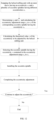
FIG. 12 is a flow diagram of the eccentricity adjustment method for the solution M1 in the embodiments of the present disclosure. - Wherein, 1 - eccentric spindle, 2 - tool, 3 - rotating shaft, 4 - gear transmission shaft, 5 - spindle, 6 - first gear, 7 - second gear, 8 - third gear, 9 - inner sleeve, 10 - spindle bearing, 11 - bearing, 12 - outer sleeve, 13 - sliding bearing, 14 - sleeve housing, 15 - first motor, 16 - lead screw coupling, 17 - lead screw support base, 18 - lead screw, 19 - second motor, 20 - translational plate, 21 - encoder support base, 22 - lead screw nut, 23 - encoder, 24 - first synchronous cog belt wheel, 25 - second synchronous cog belt wheel, 26 - third synchronous cog belt wheel, 27 - fourth synchronous cog belt wheel, 28 - transmission shaft, 29 - transmission bearing, 30 - revolution bearing, 31 - slider of optical axis, 32 - third motor, 33 - optical axis, 34 - handle, 35 - universal joint coupling, 36 - housing, 38 - positioning shaft sleeve.
- To make the objectives, technical solutions and advantages of embodiments of the present disclosure more obvious, the technical solutions of the present disclosure will be clearly and completely described below in conjunction with the accompanying drawings in the embodiments of the present disclosure, and obviously, the described embodiments are some, rather than all of the embodiments of the present disclosure. Based on the embodiments of the present disclosure, all other embodiments acquired by those of ordinary skilled in the art without making creative efforts fall within the scope of protection of the present disclosure.
- The present disclosure provides a portable helical milling unit including a
tool 2, aneccentric spindle 1, anouter sleeve 12, asleeve housing 14, and a plurality of transmission mechanisms for providing power. Theeccentric spindle 1 is detachably sleeved in an inner hole of output section of theouter sleeve 12. Each of theeccentric spindle 1 and theouter sleeve 12 has a pre-set eccentricity. Thetool 2 is in connection with the output side of theeccentric spindle 1. Theeccentric spindle 1 is detachably connected in theouter sleeve 12. Theouter sleeve 12 is installed in thesleeve housing 14 through a slidingbearing 13. An input side of theouter sleeve 12 is in connection with a first transmission mechanism and a third transmission mechanism, and an input side of theeccentric spindle 1 is in connection with a second transmission mechanism. The third transmission mechanism is used to drive theouter sleeve 12 to rotate relative to theouter sleeve housing 14 to enable thetool 2 to rotate around the axis of the outer cylindrical surface of theouter sleeve 12. The first transmission mechanism is used to drive theouter sleeve 12 to move back and forth relative to the axis direction of thesleeve housing 14 to achieve the feed motion of thetool 2. The second transmission mechanism is used to drive theeccentric spindle 1 to rotate so as to rotate thetool 2. - The output section of the
outer sleeve 12 is an eccentric structure, i.e., the axis of the outer cylindrical surface of the outer sleeve has a certain eccentricity e0 with the axis of the inner hole of the output section of theouter sleeve 14. The middle section and the input section of the outer sleeve are concentric, i.e., the axis of the outer cylindrical surface of the outer sleeve is concentric with the axes of the inner holes of the middle section and the input section of theouter sleeve 12. - The structure of the
eccentric spindle 1 has three solutions as follows:
For solution M1 as shown inFIG. 1 and FIG. 2 , when the processing object is a hole having a smaller diameter, theeccentric spindle 1 includes aspindle 5 and aninner sleeve 9 having an eccentric structure, that is, the axis of the outer cylindrical surface of theeccentric spindle 1 has a certain eccentricity en with the axis of the inner hole, and thespindle 5 is sleeved in the inner hole of theinner sleeve 9 through aspindle bearing 10. Thetool 2 is installed at the front end of thespindle 5. - For solution M2 as shown in
FIG. 4 , when the processing object is a hole having a lager diameter, theeccentric spindle 1 includes aspindle 5, aninner sleeve 9 and an eccentricity adjustment mechanism. The eccentricity adjustment mechanism includes agear transmission shaft 4, arotating shaft 3, afirst gear 6 and asecond gear 7. Theinner sleeve 9 is a concentric structure, and thespindle 5 is sleeved in the inner hole of theinner sleeve 9 through aspindle bearing 10. The output end of thespindle 5 is installed with thefirst gear 6 which is meshed with thesecond gear 7 for transmission. Thesecond gear 7 is installed at the input end of therotating shaft 3 which is installed on theinner sleeve 9 through abearing 11, and thetool 2 is installed at a front end of therotating shaft 3. A distance between axes of thefirst gear 6 and thesecond gear 7 is en. - For solution M3 as shown in
FIG. 8 , when the processing object is a hole having a lager diameter, theeccentric spindle 1 includes aninner sleeve 9, aspindle 5 and an eccentricity adjustment mechanism. The eccentricity adjustment mechanism includes agear transmission shaft 4, arotating shaft 3, afirst gear 6, asecond gear 7 and athird gear 8. Theinner sleeve 9 is a concentric structure, and thespindle 5 is sleeved in the inner hole of theinner sleeve 9 through aspindle bearing 10. The output end of thespindle 5 is installed with thefirst gear 6 which is meshed with thethird gear 8 for transmission. Thethird gear 8 is installed on thegear transmission shaft 4 and meshed with thesecond gear 7 for transmission. Thesecond gear 7 is installed at the input end of therotating shaft 3 which is installed on theinner sleeve 9 through abearing 11, and thetool 2 is installed at a front end of therotating shaft 3. A distance between axes of thefirst gear 6 and thesecond gear 7 is en. - The first transmission mechanism includes a
first motor 15 and alead screw 18. Thefirst motor 15 is horizontally installed on thesleeve housing 14. The output end of thefirst motor 15 is in connection with thelead screw 18 through alead screw coupling 16. One end of thelead screw 18 is installed in a mounting hole of a leadscrew support base 17, and the other end is sleeved in alead screw nut 22. The leadscrew support base 17 is horizontally installed on thesleeve housing 14, and thelead screw nut 22 is installed on atranslational plate 20. - The second transmission mechanism includes a
second motor 19 and atransmission shaft 28. The output end of thesecond motor 19 is in connection with the input end of thetransmission shaft 28, and the output end of thetransmission shaft 28 is in connection with the input end of thespindle 5. - The third transmission mechanism includes a
third motor 32 and a first synchronous cog belt, the input end of theouter sleeve 12 is installed with a third synchronouscog belt wheel 26. The third synchronouscog belt wheel 26 is in connection with a fourth synchronouscog belt wheel 27 installed at the output end of thethird motor 32 through the first synchronous cog belt. - The outer side of the input section of the
outer sleeve 12 is in connection with thetranslational plate 20 through arevolution bearing 30. - The
second motor 19 and thethird motor 32 are installed on thetranslational plate 20. The input end of thetransmission shaft 28 is installed with the second synchronouscog belt wheel 25 which is in connection with the first synchronouscog belt wheel 24 installed on the output end of thesecond motor 19 through the second synchronous cog belt. - The second transmission mechanism further includes an
encoder 23 for measuring a rotational speed of thespindle 5. Theencoder 23 is installed at the output end of thesecond motor 19 or the output end of thetransmission shaft 28. The housing of theencoder 23 is fixed on thetranslational plate 20 through anencoder support base 21. - The
transmission shaft 28 is installed at the input section of theouter sleeve 12 through atransmission bearing 29. A circular shaft of the output end of thetransmission shaft 28 is in connection with the input end of a universaljoint coupling 35 through a key joint, and the output end of the universaljoint coupling 35 is in connection with the input end of thespindle 5. The universaljoint coupling 35 is a double cross-shaft universal joint coupling and located in the inner hole of the middle section of theouter sleeve 12. This structure makes the two shafts not on the same axis, and can realize continuous rotation of the two linked shafts in the case of axis offset and reliably transmit torque and motion. The two ends of the universaljoint coupling 35 are respectively in connection with thespindle 5 and thetransmission shaft 28. The axis of thespindle 5 has a certain eccentricity e with the axis of the outer cylindrical surface of theouter sleeve 12, and the axis of thetransmission shaft 28 is concentric with the axis of the outer cylindrical surface of theouter sleeve 12. Therefore, the universaljoint coupling 35 can realize the transmission between thespindle 5 with a larger eccentricity and thetransmission shaft 28. - The helical filling unit further includes an optical shaft. One end of the
optical shaft 33 is fixedly installed on thesleeve housing 14, and the other end is sleeved in a slider of theoptical shaft 31. Theslider 31 is installed on thetranslational plate 20. Theoptical shaft 33 is used to maintain thetranslational plate 20 in a vertical state, i.e., thetranslational plate 20 can only move in the axis direction of thetool 2 rather than rotate. - An outer side of the output end of the
sleeve housing 14 is fixed to thehousing 36 through a flange, and both sides of the housing are installed withhandles 34. - The front side of the flange is fixed with a
positioning shaft sleeve 38. - The working principle of the revolution motion of the portable helical milling unit is as follows: the
third motor 32 drives theouter sleeve 12 to rotate relative to thesleeve housing 14 and thetranslational plate 20 by the synchronous cog belt wheel and the cog belt, so as to drive theinner sleeve 9 to rotate; when theouter sleeve 12 and theinner sleeve 9 are relatively stationary, the eccentricity e of thetool 2 relative to the outer cylindrical surface of theouter sleeve 12 keeps constant to realize the revolution motion of thetool 2. - The working principle of the feed motion of the portable helical milling unit is as follows: the
first motor 15 drives thetranslational plate 20 to move along the axis direction through thelead screw 18 so as to drive theouter sleeve 12 to move along the axis direction relative to thesleeve housing 14 to realize the axial feed motion of thetool 2. - During the process of the
second motor 19 driving thetransmission shaft 28 to rotate, the position of the axis of thetransmission shaft 28 remains unchanged when thethird motor 32 drives theouter sleeve 12 to rotate, which is convenient for thesecond motor 19 to transmit power to thetransmission shaft 28 through the synchronous cog belt wheel. - The working principle of the rotation of the
spindle 5 of the portable helical milling unit is as follows:
As for the solution M1, thesecond motor 19 drives thetransmission shaft 28 to rotate through the synchronous cog belt wheel and the cog belt, and thetransmission shaft 28 concentric with the outer cylindrical surface of theouter sleeve 12 transmits power to thespindle 5 eccentric with the outer cylindrical surface of theouter sleeve 12 through the universaljoint coupling 35, so as to drive thespindle 5 to rotate to realize the rotation of thetool 2. Theencoder 23 detects the real-time rotational speed of thetool 2. - As for the solution M2, the
second motor 19 drives thetransmission shaft 28 to rotate through the synchronous cog belt wheel and the cog belt, and thetransmission shaft 28 concentric with the outer cylindrical surface of theouter sleeve 12 transmits power to thespindle 5 eccentric with the outer cylindrical surface of theouter sleeve 12 through the universaljoint coupling 35, so as to drive thefirst gear 6 at the front end of thespindle 5 to rotate, and thefirst gear 6 drives thesecond gear 7 to rotate through meshing to realize the rotation of thetool 2 at the front end of thesecond gear 7. Theencoder 23 detects the real-time rotational speed of thespindle 5. - As for the solution M3, the
second motor 19 drives thetransmission shaft 28 to rotate through the synchronous cog belt wheel and the cog belt, and thetransmission shaft 28 concentric with the outer cylindrical surface of theouter sleeve 12 transmits power to thespindle 5 eccentric with the outer cylindrical surface of theouter sleeve 12 through the universaljoint coupling 35, so as to drive thefirst gear 6 at the front end of thespindle 5 to rotate, and thefirst gear 6 drives thethird gear 8 to rotate through meshing and thethird gear 8 drives thesecond gear 7 to rotate through meshing to realize the rotation of thetool 2 at the front end of thesecond gear 7. Theencoder 23 detects the real-time rotational speed of thespindle 5. - The working principle of the eccentricity adjustment of the portable helical milling unit is as follows:
As shown inFIG. 3 , as for the solution M1, the eccentricity adjustment method includes that:
The helical milling unit is equipped with a plurality ofeccentric spindles 1 having different specifications, i.e., theeccentric spindles 1 have different eccentricities en from each other. According to the size of the eccentricity to be adjusted, en is changed by replacing theeccentric spindle 1 with different specifications to roughly adjust the eccentricity. The outer circumferential surface of the front end of theeccentric spindle 1 is engraved with an eccentricity adjustment scale ring. Rotate theeccentric spindle 1 to produce a relative rotation between theeccentric spindle 1 and theouter sleeve 12, i.e., to change the relative position of theeccentric spindle 1 and theouter sleeve 12. Adjust the scale ring, i.e., adjust the relative angle θ between theouter sleeve 12 and theeccentric spindle 1 to finely adjust the eccentricity, so that the eccentricity e of thetool 2 relative to the outer cylindrical surface of theouter sleeve 12 is changed so as to obtain different eccentricities e of thetool 2, e =
eccentric spindle 1 and theouter sleeve 12 are fixed. - As shown in
FIG. 7 , as for the solution M2, the eccentricity adjustment method includes that:
The helical milling unit is equipped with a plurality ofeccentric spindles 1 having different specifications, i.e., the models of thefirst gear 6 and thesecond gear 7 of different eccentric spindles are different, which results in different distances en between axes of thefirst gear 6 and thesecond gear 7 of different eccentric spindles, i.e., theeccentric spindles 1 have different eccentricities en from each other. According to the size of the eccentricity to be adjusted, en is changed by replacing theeccentric spindle 1 with different specifications to roughly adjust the eccentricity. The outer circumferential surface of the front end of theeccentric spindle 1 is engraved with an eccentricity adjustment scale ring. Rotate theeccentric spindle 1 to produce a relative rotation between theeccentric spindle 1 and theouter sleeve 12, i.e., to change the relative position of theeccentric spindle 1 and theouter sleeve 12. Adjust the scale ring, i.e., adjust the relative angle θ between theouter sleeve 12 and theeccentric spindle 1 to finely adjust the eccentricity, so that the eccentricity e of thetool 2 relative to the outer cylindrical surface of theouter sleeve 12 is changed so as to obtain different eccentricities e of thetool 2,
eccentric spindle 1 and theouter sleeve 12 are fixed. - As shown in
FIG. 11 , as for the solution M3, the eccentricity adjustment method includes that:
The helical milling unit is equipped with a plurality ofeccentric spindles 1 having different specifications, i.e., the models of thefirst gear 6, thesecond gear 7 and thethird gear 8 of different eccentric spindles are different, which results in different distances en between axes of thefirst gear 6 and thesecond gear 7 of different eccentric spindles, i.e., theeccentric spindles 1 have different eccentricities en from each other. According to the size of the eccentricity to be adjusted, en is changed by replacing theeccentric spindle 1 with different specifications to roughly adjust the eccentricity. The outer circumferential surface of the front end of theeccentric spindle 1 is engraved with an eccentricity adjustment scale ring. Rotate theeccentric spindle 1 to produce a relative rotation between theeccentric spindle 1 and theouter sleeve 12, i.e., to change the relative position of theeccentric spindle 1 and theouter sleeve 12. Adjust the scale ring, i.e., adjust the relative angle θ between theouter sleeve 12 and theeccentric spindle 1 to finely adjust the eccentricity, so that the eccentricity e of thetool 2 relative to the outer cylindrical surface of theouter sleeve 12 is changed so as to obtain different eccentricities e of thetool 2,
eccentric spindle 1 and theouter sleeve 12 are fixed. - As for the solutions M2 and M3, the number of teeth of the
first gear 6 is represented as Z1, the number of teeth of thesecond gear 7 is represented as Z2, the rotational speed of thespindle 5 is represented as n1, and the rotational speed n2 of the tool satisfies n2 = n1 •Z1/Z2. - As for the solutions M2 and M3, the
tool 2 includes two forms as following:
As shown inFIG. 5 andFIG. 9 , as for solutions M21 and M31, thetool 2 is of a blade shape and is fixed on the output end of therotating shaft 3 through bolts. - As shown in
FIG. 6 andFIG. 10 , as for solutions M22 and M33, thetool 2 is of a cylindrical shape, and the back end of thetool 2 is fixed on the output end of therotating shaft 3 through a thread connection. - The material of the
tool 2 includes but not limited to hard alloy, etc. - As shown in
FIG. 12 , as for the solution M1, the eccentricity adjustment method has the following steps: - S1. The helical milling unit is equipped with an
outer sleeve 12 having a constant eccentricity and a plurality ofeccentric spindles 1 having different eccentricities, and the eccentricity of theouter sleeve 12 is set as e0 and the eccentricities of the neccentric spindles 1 are set as en (e1, e2... en ), wherein alleccentric spindles 1 have the same boundary dimension and can be installed in theouter sleeve 12 for use; - S2. According to e0 and en (e1, e2... en ) in step S1, an eccentricity adjustment range ea to eb of the helical milling unit is calculated when the corresponding eccentric spindle having the eccentricity en (e1, e2... en ) is installed, and the eccentricity adjustment ranges corresponding to the n eccentric spindles are obtained respectively satisfying |e 1 - e 0| to |e 1 + e 0|,|e 2 - e 0| to |e 2 + e 0|,...|en - e 0| to |en + e 0|;
- S3. According to processing requirements, the eccentricity e to be adjusted by the helical milling unit is calculated;
- S4. According to the eccentricity e to be adjusted obtained in step S3, the
eccentric spindle 1 having the eccentricity e contained in the eccentricity adjustment range ea to eb is selected; - S5. The
eccentric spindle 1 selected in step S4 is installed on the helical milling unit, and theeccentric spindle 1 is rotated to adjust the eccentricity to e; - S6. The eccentricity adjustment is conducted;
- S7. If it is necessary to continue to adjust the eccentricity, steps S3 to S5 are performed.
- Determining the ranges of the eccentricity e0 of the
outer sleeve 12 and the eccentricity en of theeccentric spindle 1 in step S1 includes the following steps: - S11. Based on a maximum resolution ratio of a scale line of a dial size on a scale ring of the
eccentric spindle 1, a corresponding eccentricity adjustment range value em within a maximum measuring range of the scale ring of aneccentric spindle 1 is determined, and the eccentricity e0 of theouter sleeve 12 is determined and satisfies e0 ≤em /2; - S12. According to processing requirements including a type and a diameter range of the
tool 2 to-be-used and an aperture range of the hole to-be-processed, the eccentricity adjustment range ex to ey of the helical milling unit is determined; - S13. A minimum number n of the equipped
eccentric spindles 1 is determined that
- S14. According to the eccentricity adjustment range ex to ey determined in step S12 and the number n of the
eccentric spindles 1 calculated in step S13, the adjustment eccentricity range ea to eb corresponding to the neccentric spindles 1 is determined and satisfies eα~eb ∈ ex~ey,
that is, [|e 1-e 0|,|e 1+e 0|]∪[|e 2-e 0|,|e 2+e 0|]∪···∪[|en-e 0|,|en +e 0|]∈[ex ,ey ]; - 515. According to the eccentricity e0 of the
outer sleeve 12 determined in step S11 and the adjustment eccentricity range ea to eb corresponding to the neccentric spindles 1 determined in step S14 (i.e., |e 1 - e0| to|e 1 + e 0| , |e 2 - e 0| to|e 2 + e 0| ,... |en - e 0| to |en + e 0| ), the eccentricities of the neccentric spindles 1 are determined to be en (e1, e2... en); - The adjustment solutions of M2 and M3 are basically the same as that of M1. As for the solution M2, the eccentricity adjustment method includes the following steps that:
The helical milling unit is equipped with a plurality of eccentric spindles having different specifications, i.e., the models of the first gear and the second gear of different eccentric spindles are different, which results in different distances en between axes of the first gear and the second gear. According to the size of the eccentricity to be adjusted, the distance en between axes is changed by replacing the eccentric spindle with different specifications to roughly adjust the eccentricity. By rotating the eccentric spindle to enable it to rotate relative to the outer sleeve, the relative angle θ between the outer sleeve and the eccentric spindle is adjusted to finely adjust the eccentricity so as to change the eccentricity e of the tool relative to the outer cylindrical surface of the outer sleeve, so that different eccentricities of the helical milling unit are obtained to be
- As for the solution M3, the eccentricity adjustment method includes the following steps that:
The helical milling unit is equipped with a plurality of eccentric spindles having different specifications, i.e., the models of the first gear, the second gear and the third gear are different, which results in different distances en between axes of different eccentric spindles. According to the size of the eccentricity to be adjusted, the distance en between axes are changed by replacing the eccentric spindle with different specifications to roughly adjust the eccentricity. By rotating the eccentric spindle to enable it to rotate relative to the outer sleeve, the relative angle θ between the outer sleeve and the eccentric spindle is adjusted to finely adjust the eccentricity so as to change the eccentricity e of the tool relative to the outer cylindrical surface of the outer sleeve, so that different eccentricities of the helical milling unit are obtained to be
- Taking the solution M1 as an example for helical milling:
In the embodiment, the eccentricity e0 of theouter sleeve 12 of the helical milling unit is 0.5, the milling cutter ϕ8 is used to process the holes ϕ10 and ϕ13. The processing steps are as follows: - S1. Select an
outer sleeve 12 having an eccentricity e0 of 0.5 and foureccentric spindles 1 having eccentricities en of 0.5, 1.5, 2.5 and 3.5 respectively; - S2. According to e 0=0.5 and e n=0.5, 1.5, 2.5 and 3.5 in step S1, the eccentricity adjustment range ea to eb of the helical milling unit corresponding to the
eccentric spindles 1 having eccentricities e n=0.5, 1.5, 2.5 and 3.5 is calculated, and the corresponding eccentricity adjustment ranges of the 4eccentric spindles 1 are respectively [0, 1], [1, 2], [2, 3] and [3, 4]; - S3. According to the diameter D=ϕ10 of the hole to-be-processed and the diameter d=ϕ8 of the
milling cutter 2 to-be-used, the theoretical value of the eccentricity e to be adjusted by the helical milling unit is calculated, i.e., e = (D-d) / 2 = 1; - S4. According to the theoretical value of the eccentricity e=1 to be adjusted obtained in step S3, the
eccentric spindle 1 having an eccentricity adjustment range eab = [1, 2] is selected; - S5. The
eccentric spindle 1 selected in step S4 is installed on the helical milling unit, and the adjustment eccentricity e is 1; - S6. The workpiece to-be-processed and the
milling tool 2 are clamped to helical milling of the hole; - S7. According to the diameter D=ϕ13 of the hole to-be-processed and the diameter d=ϕ8 of the
milling cutter 2 to-be-used, the theoretical value of the eccentricity e to be adjusted by the helical milling unit is calculated, i.e., e = (D-D) / 2 = 2.5; - S8. According to the theoretical value of the eccentricity e=2.5 to be adjusted obtained in step S7, the
eccentric spindle 1 having an eccentricity adjustment range eab = [2, 3] is selected; - S9. The
eccentric spindle 1 selected in step S8 is installed on the helical milling unit, and the adjustment eccentricity e is 2.5; - S10. The workpiece to-be-processed and the
milling cutter 2 are clamped to the helical milling unit to helical milling of the hole; - S11. The hole machining is conducted.
- At last, it should be noted that the above various embodiments are merely intended to illustrate the technical solution of the present disclosure and not to limit the same; although the present disclosure has been described in detail with reference to the foregoing embodiments, it should be understood by those ordinary skilled in the art that the technical solutions described in the foregoing embodiments can be modified or equivalents can be substituted for some or all of the technical features thereof; and the modification or substitution does not make the essence of the corresponding technical solution deviate from the scope of the technical solution of each embodiment of the present disclosure.
Claims (17)
- A portable helical milling unit comprising a tool, an eccentric spindle, an outer sleeve, a sleeve housing, and a plurality transmission mechanisms for providing power, wherein the eccentric spindle is detachably sleeved in an inner hole of output section of the outer sleeve, each of the eccentric spindle and the outer sleeve both has a pre-set eccentricity, the tool is in connection with an output side of the eccentric spindle, the eccentric spindle is detachably in connection with the outer sleeve, the outer sleeve is installed in the sleeve housing through a sliding bearing, an input side of the outer sleeve is in connection with a first transmission mechanism and a third transmission mechanism, an input side of the eccentric spindle is in connection with a second transmission mechanism, wherein the third transmission mechanism is used to drive the outer sleeve to rotate relative to the outer sleeve housing to enable the tool to rotate around an axis of outer cylindrical surface of the outer sleeve, the first transmission mechanism is used to drive the outer sleeve to move back and forth relative to an axis direction of the sleeve housing to achieve the feed motion of the tool, and the second transmission mechanism is used to drive the eccentric spindle to rotate so as to rotate the tool.
- The portable helical milling unit according to claim 1, wherein the output section of the outer sleeve is an eccentric structure, that is, an axis of the outer cylindrical surface of the outer sleeve has a certain eccentricity e0 with an axis of the inner hole of the output section of the outer sleeve, and an middle section and an input section of the outer sleeve are concentric, that is, the axis of the outer cylindrical surface of the outer sleeve is concentric with the axis of the inner holes of the middle section and the input section of the outer sleeve, wherein the eccentric spindle comprises a spindle and an inner sleeve having an eccentric structure, that is, the axis of the outer cylindrical surface of the eccentric spindle has a certain eccentricity en with the axis of the inner hole of the output section of the outer sleeve, and the spindle is sleeved in the inner hole of the inner sleeve through a spindle bearing.
- The portable helical milling unit according to claim 1, wherein the output section of the outer sleeve is an eccentric structure, that is, the axis of the outer cylindrical surface of the outer sleeve has a certain eccentricity e0 with the axis of the inner hole of the output section of the outer sleeve, and the middle section and the input section of the outer sleeve are concentric, that is, the axis of the outer cylindrical surface of the outer sleeve is concentric with the axis of the inner holes of the middle section and the input section of the outer sleeve, wherein the eccentric spindle comprises a tool, an inner sleeve, a spindle and an eccentricity adjustment mechanism, wherein eccentricity adjustment mechanism comprises a gear transmission shaft, a rotating shaft, a first gear, and a second gear, wherein the inner sleeve is a concentric structure, the spindle is sleeved in the inner hole of the inner sleeve through a spindle bearing, the output end of the spindle is installed with the first gear which is meshed with the second gear for transmission, the second gear is installed at the input end of the rotating shaft, the rotating shaft is installed on the inner sleeve through a bearing, the tool is installed at a front end of the rotating shaft, and a distance between axes of the first gear and the second gear is en.
- The portable helical milling unit according to claim 1, wherein the output section of the outer sleeve is an eccentric structure, that is, the axis of the outer cylindrical surface of the outer sleeve has a certain eccentricity e0 with the axis of the inner hole of the output section inner hole of the outer sleeve, and the middle section and the input section of the outer sleeve are concentric, that is, the axis of the outer cylindrical surface of the outer sleeve is concentric with the axis of the inner holes of the middle section and the input section of the outer sleeve, wherein the eccentric spindle comprises a tool, an inner sleeve, a spindle and an eccentricity adjustment mechanism, wherein eccentricity adjustment mechanism comprises a gear transmission shaft, a rotating shaft, a first gear, a second gear, and a third gear, wherein the inner sleeve is a concentric structure, the spindle is sleeved in the inner hole of the inner sleeve through a spindle bearing, the output end of the spindle is installed with the first gear which is meshed with the third gear for transmission, the third gear is installed at the gear transmission shaft and meshed with the second gear for transmission, the second gear is installed at the input end of the rotating shaft, the rotating shaft is installed on the inner sleeve through a bearing, the tool is installed at a front end of the rotating shaft, and a distance between axes of the first gear and the second gear is en.
- The portable helical milling unit according to any claims of 1 to 4, wherein each of the first transmission mechanism, the second transmission mechanism and the third transmission mechanism is in connection with the sleeve housing through a connecting piece.
- The portable helical milling unit according to claim 5, whereinthe first transmission mechanism comprises a first motor and a lead screw, wherein the first motor is horizontally installed on the sleeve housing, and the output end of the first motor is in connection with the lead screw through a lead screw coupling, wherein one end of the lead screw is installed in a mounting hole of a lead screw support base, and the other end is sleeved in a lead screw nut, wherein the lead screw support base is horizontally installed on the sleeve housing, and the lead screw nut is installed on a translational plate;the second transmission mechanism comprises a second motor and a transmission shaft, wherein the output end of the second motor is in connection with the input end of the transmission shaft, and the output end of the transmission shaft is in connection with the input end of the spindle;the third transmission mechanism comprises a third motor and a first synchronous cog belt, and the input end of the outer sleeve is installed with a third synchronous cog belt wheel, wherein the third synchronous cog belt wheel is in connection with a fourth synchronous cog belt wheel installed at the output end of the third motor through the first synchronous cog belt; andthe outer side of the input section of the outer sleeve is in connection with the translational plate through a revolution bearing.
- The portable helical milling unit according to claim 6, wherein the second motor and the third motor are installed on the translational plate, the input end of the transmission shaft is installed with the second synchronous cog belt wheel which is in connection with the first synchronous cog belt wheel installed on the output end of the second motor through the second synchronous cog belt.
- The portable helical milling unit according to claim 6, wherein the second transmission mechanism further comprises an encoder for measuring a rotational speed of the spindle, wherein the encoder is installed at the output end of the second motor or the output end of the transmission shaft, and the housing of the encoder is fixed on the translational plate through an encoder support base.
- The portable helical milling unit according to claim 6, wherein the transmission shaft is installed at the input section of the outer sleeve through a transmission bearing, a circular shaft of the output end of the transmission shaft is in connection with the input end of a universal joint coupling through a key joint, and the output end of the universal joint coupling is in connection with the input end of the spindle.
- The portable helical milling unit according to claim 6, further comprising an optical shaft, wherein one end of the optical shaft is fixedly installed on the sleeve housing and the other end is sleeved in a slider of the optical shaft slider, the slider of the optical shaft is installed on the translational plate, the optical shaft is used to maintain the translational plate in a vertical state, that is, the translational plate can only move in the axis direction of the tool rather than rotate.
- The portable helical milling unit according to claim 1, wherein the outer side of the output end of the sleeve housing is fixed to the sleeve housing through a flange, and both sides of the sleeve housing are provided with handles.
- The portable helical milling unit according to claim 9, wherein the universal joint coupling is a double cross shaft universal joint coupling.
- The portable helical milling unit according to claim 3 or claim 4, wherein a number of teeth of the first gear is represented as Z1, a number of teeth of the second gear is represented as Z2, a rotational speed of the spindle is represented as n1, and a rotational speed n2 of the tool satisfies n2 = n1 •Z1/Z2.
- An eccentricity adjustment method for the portable helical milling unit in claim 2, comprising following steps of:S1. equipping the helical milling unit with an outer sleeve having a constant eccentricity and a plurality of eccentric spindles having different eccentricities, and setting the eccentricity of the outer sleeve as e0 and the eccentricities of the n eccentric spindles as en (e1, e2... en ), wherein all eccentric spindles have the same boundary dimensions and can be installed in the outer sleeve for use;S2. calculating, according to e0 and en (e1, e2... en ) in step S1, an eccentricity adjustment range ea to eb of the helical milling unit when installing the corresponding eccentric spindle having the eccentricity of en (e1, e2... en ), and obtaining the eccentricity adjustment ranges corresponding to the n eccentric spindles respectively satisfying |e 1 - e 0| to |e 1 + e 0| , |e 2 - e 0| to |e 2 + e 0|, ... |en - e 0| to |en + e 0|;S3. calculating, according to processing requirements, the adjustment eccentricity e to be adjusted of the helical milling unit;S4. selecting, according to the eccentricity e to be adjusted obtained in step S3, the eccentric spindle having the eccentricity e contained in the eccentricity adjustment range ea to eb ;S5. installing the eccentric spindle selected in step S4 on the helical milling unit, and rotating the eccentric spindle to adjust the eccentricity to e;S6. conducting the eccentricity adjustment; andS7. if it is necessary to continue to adjust the eccentricity, performing steps S3 to S5.
- The eccentricity adjustment method according to claim 14, wherein determining ranges of the eccentricity e0 of the outer sleeve and the eccentricity en of the eccentric spindle in step S1 comprises the following steps of:S11. determining, based on a maximum resolution ratio of a scale line of a dial size on a scale ring of the eccentric spindle, a corresponding eccentricity adjustment range value em within a maximum measuring range of the scale ring of an eccentric spindle, and determining the eccentricity e0 of the outer sleeve satisfying e 0≤em /2;S12. determining, according to processing requirements including a type and a diameter range of the tool to-be-used and an aperture range of the hole to-be-processed, an eccentricity adjustment range ex to ey of the helical milling unit;S13. determining a minimum number n of the equipped eccentric spindles satisfying
 S14. determining, according to the eccentricity adjustment range ex to ey determined in step S12 and the number n of the eccentric spindles calculated in step S13, the adjustment eccentricity range ea to eb corresponding to the n eccentric spindles satisfying ea~eb E ex~ey, that is, [|e 1-e 0|,|e 1 +e 0|]∪[|e 2 -e 0|,|e 2 +e 0|]∪···∪[|e n -e 0|,|en +e 0|]∈[ex,ey ]; andS15. determining, according to the eccentricity e0 of the outer sleeve determined in step S11 and the adjustment eccentricity range ea to eb corresponding to the n eccentric spindles determined in step S14, that is, |e 1 - e 0| to |e 1 + e 0|, |e 2 - e 0| to |e 2 + e 0|, ... |en - e 0| to |en + e 0|, the eccentricities of the n eccentric spindles to be en (e1, e2... en).
 - The eccentricity adjustment method according to claim 14, wherein in step S5, rotating the eccentric spindle to enable it to rotate relative to the outer sleeve to finely adjust the eccentricity, and by adjusting the relative rotation angle θ between the outer sleeve and the eccentric spindle, changing the eccentricity of the tool relative to the outer cylindrical surface of the outer sleeve so as to obtain different eccentricities e of the helical milling unit, e =

- The eccentricity adjustment method of the portable helical milling unit in claim 3 or claim 4, comprising the following steps of: according to the size of the eccentricity to be adjusted, changing the distance en between axes by replacing the eccentric spindle with different specifications to roughly adjust eccentricity, wherein the outer circumferential surface of the front end of the eccentric spindle is engraved with an eccentricity adjustment scale ring, by rotating the eccentric spindle to enable it to rotate relative to the outer sleeve, that is, changing the relative position of the outer sleeve and the eccentric spindle, and adjusting the scale ring, that is, adjusting the relative angle θ between the outer sleeve and the eccentric spindle to finely adjust the eccentricity, thereby changing the eccentricity e of the tool relative to the outer cylindrical surface of the outer sleeve so as to obtain different eccentricities e of the tool to be

after completion of the angle adjustment, fixing the eccentric spindle and the outer sleeve.
Applications Claiming Priority (1)
| Application Number | Priority Date | Filing Date | Title |
|---|---|---|---|
| PCT/CN2020/085591 WO2021212263A1 (en) | 2020-04-20 | 2020-04-20 | Portable helical milling unit and eccentricity adjustment method |
Publications (2)
| Publication Number | Publication Date |
|---|---|
| EP4140625A1 true EP4140625A1 (en) | 2023-03-01 |
| EP4140625A4 EP4140625A4 (en) | 2023-06-07 |
Family
ID=78271001
Family Applications (1)
| Application Number | Title | Priority Date | Filing Date |
|---|---|---|---|
| EP20932386.4A Pending EP4140625A4 (en) | 2020-04-20 | 2020-04-20 | PORTABLE HELICAL MILLING UNIT AND ECCENTRICITY SETTING METHOD |
Country Status (3)
| Country | Link |
|---|---|
| US (1) | US20230211426A1 (en) |
| EP (1) | EP4140625A4 (en) |
| WO (1) | WO2021212263A1 (en) |
Cited By (1)
| Publication number | Priority date | Publication date | Assignee | Title |
|---|---|---|---|---|
| CN116140675A (en) * | 2023-03-30 | 2023-05-23 | 中国长江电力股份有限公司 | Guide vane sleeve overhauling method of water guide mechanism of hydropower station unit |
Families Citing this family (4)
| Publication number | Priority date | Publication date | Assignee | Title |
|---|---|---|---|---|
| CN117428694B (en) * | 2023-10-27 | 2026-02-10 | 大连理工大学 | An adjustable simulation eccentricity tooling and its method |
| CN117260514B (en) * | 2023-11-22 | 2024-02-09 | 北京特思迪半导体设备有限公司 | Precise control method of eccentric drive mechanism |
| CN118060599B (en) * | 2024-03-21 | 2024-12-27 | 扬州晶玖汽车配件有限公司 | High-precision milling process for engine cylinder block |
| CN118288053A (en) * | 2024-05-15 | 2024-07-05 | 中煤科工集团重庆研究院有限公司 | Eccentric chip breaking processing method, eccentric displacement spindle and chip breaking processing equipment |
Family Cites Families (18)
| Publication number | Priority date | Publication date | Assignee | Title |
|---|---|---|---|---|
| ES479883A1 (en) * | 1979-04-24 | 1980-01-16 | Sanchez Velasco Vicente | Milling apparatus for widening drill-holes and perforations |
| EP0237035B1 (en) * | 1986-03-13 | 1993-06-09 | Turchan, Manuel C. | Method of and tool for thread mill drilling |
| SE9300400L (en) * | 1993-02-05 | 1994-08-06 | Strukturteknologier I Stockhol | Machine tool for receiving a through opening in a fiber composite article |
| US5971678A (en) * | 1998-06-05 | 1999-10-26 | Novator Ab | Spindle unit |
| JP3518443B2 (en) * | 1998-10-09 | 2004-04-12 | トヨタ自動車株式会社 | Machining method |
| US6719505B2 (en) * | 1999-09-01 | 2004-04-13 | Novator Ab | Orbital hand tool apparatus for drilling |
| US6382890B1 (en) * | 1999-09-01 | 2002-05-07 | Novator Ab | Hand tool apparatus for orbital drilling |
| JP4019423B2 (en) * | 2001-07-20 | 2007-12-12 | ノバトール アーベー | Numerically controlled orbital machining equipment |
| EP2248619A1 (en) * | 2002-09-16 | 2010-11-10 | Novator AB | An orbital machining apparatus for producing holes and a radial offset mechanism of such an apparatus |
| FR2952841B1 (en) * | 2009-11-26 | 2011-12-02 | Airbus Operations Sas | DEVICE FOR DRILLING A COMPLEX PANEL |
| CN102892538A (en) * | 2010-01-29 | 2013-01-23 | 柳下福藏 | Boring device |
| CN103128354B (en) * | 2013-01-31 | 2015-03-11 | 南京航空航天大学 | Hand-held helical milling device and helical milling method using eccentric adjustment mechanism |
| CN103192125B (en) * | 2013-03-28 | 2014-11-12 | 大连理工大学 | Portable spiral hole milling device and machining method |
| CN103659403B (en) * | 2013-11-25 | 2016-01-20 | 中国航空工业集团公司北京航空制造工程研究所 | The punching device in on-line tuning drilling aperture |
| CN105033768B (en) * | 2015-06-04 | 2017-07-21 | 大连理工大学 | Eccentricity detection and control method of a helical milling device |
| CN106077774B (en) * | 2016-07-07 | 2018-01-30 | 大连理工大学 | An ultrasonic spiral milling device and processing method |
| FR3085011B1 (en) * | 2018-08-16 | 2020-12-04 | Advanced Electrical Tools | ORBITAL DRILLING PROCESS AND ORBITAL DRILLING DEVICE |
| CN108927557B (en) * | 2018-08-17 | 2024-02-13 | 西安增材制造国家研究院有限公司 | Spiral hole milling device and method |
-
2020
- 2020-04-20 WO PCT/CN2020/085591 patent/WO2021212263A1/en not_active Ceased
- 2020-04-20 US US17/996,686 patent/US20230211426A1/en not_active Abandoned
- 2020-04-20 EP EP20932386.4A patent/EP4140625A4/en active Pending
Cited By (1)
| Publication number | Priority date | Publication date | Assignee | Title |
|---|---|---|---|---|
| CN116140675A (en) * | 2023-03-30 | 2023-05-23 | 中国长江电力股份有限公司 | Guide vane sleeve overhauling method of water guide mechanism of hydropower station unit |
Also Published As
| Publication number | Publication date |
|---|---|
| EP4140625A4 (en) | 2023-06-07 |
| WO2021212263A1 (en) | 2021-10-28 |
| US20230211426A1 (en) | 2023-07-06 |
Similar Documents
| Publication | Publication Date | Title |
|---|---|---|
| US20230211426A1 (en) | Portable helical milling unit and eccentricity adjustment method | |
| CN101653840B (en) | Synchronous adjustable multi-shaft device and power head | |
| CN102896354B (en) | Hydraulic turbine exterior admission water ring guide vane shaft holes of both processing method and processing unit (plant) thereof | |
| EP4176995B1 (en) | Apparatus for machining double enveloping worm shaft | |
| CN112872437A (en) | Portable spiral hole milling device | |
| EP0141651A2 (en) | A chuck for a machine tool | |
| US4512694A (en) | Method and apparatus for alignment of gearing | |
| CN101219489A (en) | Trimming circle shear overlapping amount adjusting device, manufacturing method and assembling process | |
| CN110193708A (en) | Super-large diameter multisection type ring gear machining method | |
| CN101862938B (en) | Manufacturing method and assembly process of trimming disc shear overlapping amount adjustment device | |
| CN214237185U (en) | Eccentric clamping fixture applied to five-axis milling | |
| CN116037977B (en) | Adjustable quick-positioning bench drill for machining | |
| CN111482640B (en) | Portable spiral hole milling unit for large-diameter intersection holes | |
| US4838741A (en) | Method for making an epicyclic speed reducer with two stage integral rotor | |
| CN102528470B (en) | Double-sided right-angle milling head | |
| US2915949A (en) | End mill driving attachment | |
| CN220388717U (en) | Steel plate double-groove cutting guide wheel device | |
| CN111482641B (en) | A kind of eccentric adjustment method of helical milling hole | |
| CN201500797U (en) | Self-boring device of speed reducer | |
| CN101693304B (en) | Self-boring machining device of speed reducer | |
| CN111482638A (en) | Portable spiral hole milling unit | |
| CN211564556U (en) | Boring machine for narrow space | |
| EP0060453A2 (en) | Numerically controlled cross-feed facing unit for multiple spindle head machine tools | |
| CN214770830U (en) | B-type dividing head | |
| CN222199106U (en) | A saw blade power tool holder |
Legal Events
| Date | Code | Title | Description |
|---|---|---|---|
| STAA | Information on the status of an ep patent application or granted ep patent |
Free format text: STATUS: THE INTERNATIONAL PUBLICATION HAS BEEN MADE |
|
| PUAI | Public reference made under article 153(3) epc to a published international application that has entered the european phase |
Free format text: ORIGINAL CODE: 0009012 |
|
| STAA | Information on the status of an ep patent application or granted ep patent |
Free format text: STATUS: REQUEST FOR EXAMINATION WAS MADE |
|
| 17P | Request for examination filed |
Effective date: 20221117 |
|
| AK | Designated contracting states |
Kind code of ref document: A1 Designated state(s): AL AT BE BG CH CY CZ DE DK EE ES FI FR GB GR HR HU IE IS IT LI LT LU LV MC MK MT NL NO PL PT RO RS SE SI SK SM TR |
|
| A4 | Supplementary search report drawn up and despatched |
Effective date: 20230508 |
|
| RIC1 | Information provided on ipc code assigned before grant |
Ipc: B23Q 5/34 20060101ALI20230428BHEP Ipc: B23C 9/00 20060101ALI20230428BHEP Ipc: B23C 3/00 20060101AFI20230428BHEP |
|
| DAV | Request for validation of the european patent (deleted) | ||
| DAX | Request for extension of the european patent (deleted) | ||
| STAA | Information on the status of an ep patent application or granted ep patent |
Free format text: STATUS: EXAMINATION IS IN PROGRESS |