EP4140614A1 - Press forming method - Google Patents
Press forming method Download PDFInfo
- Publication number
- EP4140614A1 EP4140614A1 EP21814523.3A EP21814523A EP4140614A1 EP 4140614 A1 EP4140614 A1 EP 4140614A1 EP 21814523 A EP21814523 A EP 21814523A EP 4140614 A1 EP4140614 A1 EP 4140614A1
- Authority
- EP
- European Patent Office
- Prior art keywords
- forming
- flange
- forming step
- bottom edge
- press forming
- Prior art date
- Legal status (The legal status is an assumption and is not a legal conclusion. Google has not performed a legal analysis and makes no representation as to the accuracy of the status listed.)
- Granted
Links
Images




Classifications
-
- B—PERFORMING OPERATIONS; TRANSPORTING
- B21—MECHANICAL METAL-WORKING WITHOUT ESSENTIALLY REMOVING MATERIAL; PUNCHING METAL
- B21D—WORKING OR PROCESSING OF SHEET METAL OR METAL TUBES, RODS OR PROFILES WITHOUT ESSENTIALLY REMOVING MATERIAL; PUNCHING METAL
- B21D19/00—Flanging or other edge treatment, e.g. of tubes
- B21D19/08—Flanging or other edge treatment, e.g. of tubes by single or successive action of pressing tools, e.g. vice jaws
-
- B—PERFORMING OPERATIONS; TRANSPORTING
- B21—MECHANICAL METAL-WORKING WITHOUT ESSENTIALLY REMOVING MATERIAL; PUNCHING METAL
- B21D—WORKING OR PROCESSING OF SHEET METAL OR METAL TUBES, RODS OR PROFILES WITHOUT ESSENTIALLY REMOVING MATERIAL; PUNCHING METAL
- B21D22/00—Shaping without cutting, by stamping, spinning, or deep-drawing
- B21D22/20—Deep-drawing
- B21D22/26—Deep-drawing for making peculiarly, e.g. irregularly, shaped articles
-
- B—PERFORMING OPERATIONS; TRANSPORTING
- B21—MECHANICAL METAL-WORKING WITHOUT ESSENTIALLY REMOVING MATERIAL; PUNCHING METAL
- B21D—WORKING OR PROCESSING OF SHEET METAL OR METAL TUBES, RODS OR PROFILES WITHOUT ESSENTIALLY REMOVING MATERIAL; PUNCHING METAL
- B21D24/00—Special deep-drawing arrangements in, or in connection with, presses
- B21D24/005—Multi-stage presses
-
- B—PERFORMING OPERATIONS; TRANSPORTING
- B21—MECHANICAL METAL-WORKING WITHOUT ESSENTIALLY REMOVING MATERIAL; PUNCHING METAL
- B21D—WORKING OR PROCESSING OF SHEET METAL OR METAL TUBES, RODS OR PROFILES WITHOUT ESSENTIALLY REMOVING MATERIAL; PUNCHING METAL
- B21D53/00—Making other particular articles
- B21D53/88—Making other particular articles other parts for vehicles, e.g. cowlings, mudguards
-
- B—PERFORMING OPERATIONS; TRANSPORTING
- B21—MECHANICAL METAL-WORKING WITHOUT ESSENTIALLY REMOVING MATERIAL; PUNCHING METAL
- B21D—WORKING OR PROCESSING OF SHEET METAL OR METAL TUBES, RODS OR PROFILES WITHOUT ESSENTIALLY REMOVING MATERIAL; PUNCHING METAL
- B21D22/00—Shaping without cutting, by stamping, spinning, or deep-drawing
- B21D22/20—Deep-drawing
- B21D22/24—Deep-drawing involving two drawing operations having effects in opposite directions with respect to the blank
Definitions
- the present invention relates to a press forming method applicable to press forming of a member such as an automotive part from a metal sheet, and particularly relates to a press forming method applicable to press forming parts having a top portion, a side wall portion having a portion in which a wall height changes in a side view, and a flange portion formed on a bottom edge which is a side portion of the side wall portion provided on an opposite side of the top portion.
- Patent Literature 1 discloses a press forming method that uses a wrinkle suppression pad (blank holder) driven separately from a punch and a die and makes it possible to manufacture an automotive part which is likely to cause wrinkles and stretch flange fractures inside a product with no forming defectiveness.
- the method disclosed in Patent Literature 1 is considered to be able to manufacture an automotive part that is likely to cause wrinkles and fractures inside a product without forming defectiveness.
- Patent Literature 1 JP 6032374 B2
- Patent Literature 1 is a method that needs to hold down the inside of the product away from the flange using a wrinkle suppression pad. Therefore, the method has a problem that the technique cannot be applied to a shape having occurrence of wrinkles or fractures in the flange portion itself.
- the present invention has been made in view of the above problem, and aims to provide a press forming method applicable to a press forming part having an occurrence of wrinkles and fractures in a flange itself and capable of simultaneously suppressing the wrinkle and fracture occurring in the flange.
- a press forming method for forming a press forming part, the press forming part including: a top portion; a side wall portion continuous from the top portion, the side wall portion having a recessed portion in which a bottom edge, which is an end on an opposite side of the top portion in a side view, is recessed toward the top portion; and a flange portion formed outward on the bottom edge of the side wall portion, the recessed portion including a first curved portion continuous with the bottom edge being a portion having a large wall depth, an inclined side portion continuous with the first curved portion, a second curved portion continuous with the inclined side portion, and a recessed side portion having a small wall depth, arranged in order from the bottom edge being a portion having a large wall depth, the flange portion being formed such that the flange portion formed in the first curved portion becomes a shrink flange while a flange formed in the second curved portion becomes a stretch flange, includes: a first forming step of forming a preformed
- the first forming step and the second forming step may be performed by using different dies.
- the first forming step and the second forming step may be performed with one die.
- occurrence of wrinkles due to shrink flange forming is suppressed in the first forming step, and occurrence of fractures due to stretch flange forming is suppressed in the second forming step, leading to achievement of suppression of occurrence of wrinkles and fractures throughout all steps.
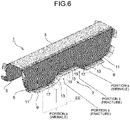
- a press forming part 1 illustrated in FIG. 6 is a floor front cross member which is an automotive part.
- the press forming part 1 includes a top portion 3; a side wall portion 5 continuous from the top portion 3, the side wall portion 5 having a recessed portion 7 in which a bottom edge, which is a side portion opposite to the top portion 3 in a side view, is recessed toward the top portion 3; and a flange portion 9 formed outward on the bottom edge of the side wall portion 5.
- the recessed portion 7 includes: a pair of inclined side portions 13 continuous from the bottom edge 11 being a portion having a large wall depth; and a recessed side portion 15 connecting ends of the inclined side portions 13 and having a small wall depth.
- a pair of first curved portions 17 curved from the bottom edge being a portion having a large wall depth to the inclined side portion 13; and a pair of second curved portions 19 curved from the inclined side portion 13 to a portion having a small wall depth.
- the flange portion 9 formed in the first curved portion 17 is subjected to shrink flange forming
- the flange portion 9 formed in the second curved portion 19 is subjected to stretch flange forming.
- FIG. 7 is a diagram illustrating a material flow in the forming process in portion EE surrounded by the square broken line in FIG. 6 , illustrating a top view (FIG. 6(a)) and a side view of (FIG. 6(b)) of FIG. 6 .
- a broken line is a tip of the blank before forming
- a solid line is an edge of the flange portion 9 formed into a target shape.
- points D and B in the drawing correspond to R-finish of the first curved portion 17 in the blank before forming, and corresponding intersections of lines extending perpendicular to the edge of the target shape from points D and B in the side view and the edge of the target shape are points D' and B'.
- points A and E in the drawing correspond to R-finish (the boundary between a curve and strait line) of the second curved portion 19 in the blank before forming, and corresponding intersections of lines extending perpendicular to the edge of the target shape from points E and A in the side view and the edge of the target shape are points A' and E'.
- the inventors have devised a press forming method in which a preformed part, which facilitates inflow of a material from a portion where shrink flange forming occurs to a portion where stretch flange forming occurs, is interposed in the middle of forming, thereby enabling avoidance of concentration of compressive strain and tensile strain in each of the portions.
- the press forming method has the following configuration.
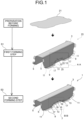
- the press forming method includes: a first forming step S1 of forming a metal sheet 21 being a blank into a preformed part 23; and a second forming step S3 of forming the preformed part 23 formed in the first forming step S1 into a target shape.
- a first forming step S1 of forming a metal sheet 21 being a blank into a preformed part 23 includes: a second forming step S3 of forming the preformed part 23 formed in the first forming step S1 into a target shape.
- the first forming step S1 is a step of forming the preformed part 23.
- the preformed part 23 includes: a side wall portion 5; a flange portion 9 formed in a bottom edge 11 being a portion having a large wall depth and in the first curved portion 17, and a torsional shape portion 25 formed in an inclined side portion 13 continuous from the flange portion 9 toward the second curved portion 19 in the target shape.
- the flange portion 9 is formed in the bottom edge 11 being the portion having a large wall depth and in the first curved portion 17, but the torsional shape portion 25, instead of the flange portion 9, is formed in the inclined side portion 13.
- the torsional shape portion 25 has one end side connected to the flange portion 9 formed in the first curved portion 17 while having the other end side connected to a blank end 15a before forming, resulting in forming the torsional shape.
- the metal inflow occurs from the flange portion 9 side of the first curved portion 17 to the torsional shape portion 25, alleviating the excess metal in the shrink flange forming, making it possible to suppress occurrence of wrinkles.
- FIG. 3 is a view illustrating the material flow in the forming process in portion CC surrounded by the broken line in FIG. 2 , illustrating a top view and a side view of the preformed part 23 in FIG. 2 .
- a fine broken line is an edge of the blank before forming
- a coarse broken line is an edge of the preformed part 23
- a solid line is an edge of the flange portion 9 in the target shape.
- Points A to E and points A' to E' in the drawing are the same as those illustrated in FIG. 7 . That is, point A is an R-finish of the second curved portion 19 in the blank, and is a tip position of the torsional shape portion 25.
- Point B is a point corresponding to one R-finish (refer to FIG. 7 ) of the blank portion having occurrence of shrink flange forming in a conventional case, and point B' is an intersection of a straight line extending perpendicularly to the edge of the torsional shape portion 25 from point B in the side view and the edge of the torsional shape portion 25.
- Point D is an R-finish of the first curved portion 17 of the blank, and point D' is an intersection of a line perpendicular to the edge of the target shape from point D in the side view and the edge of the target shape.
- the distance from point B' to point D' is shorter than the distance from point B to point D (B'D' ⁇ BD), and wrinkles are likely to occur in the first curved portion 17 due to the excess metal caused by formation of the flange portion 9.
- the distance from point A to point B' is longer than the distance from point A to point B (AB' > AB) in a three-dimensional view, the material is pulled toward point A and flows while deviating from "substantially perpendicular to the ridge line" illustrated in portion a of FIG. 7 . Therefore, the material flow indicated by the arrow in FIG.
- a bending portion 27 may be formed at an intermediate portion of the side wall portion 5 in the height direction having an angle at which the opening side of the side wall portion 5 opens outward.
- the reason for this is as follows.
- forming the flange portion 9 while the side wall portion 5 is kept vertical would increase a bending angle between the side wall portion 5 and the flange portion 9 due to springback, leading to high probability of occurrence of curl in the side wall portion 5.
- the flange portion 9 can be formed with a tool having a downward V-shaped tip.
- the second forming step S3 is a step of forming the torsional shape portion 25 of the preformed part 23 formed in the first forming step S1 into the flange portion 9, and forming the flange portion 9 in the second curved portion 19 continuous from the inclined side portion 13 and in the recessed side portion 15 having a small wall depth so as to achieve formation of a target shape.
- the excess metal causes the metal inflow into the stretch flange forming portion, alleviating the material shortage of the stretch flange forming portion, leading to suppression of occurrence of fracture.
- FIG. 5 is a view illustrating the material flow in the forming process of the DD portion surrounded by the broken line in FIG. 4 , illustrating a top view and a side view of FIG. 4 .
- a fine broken line is an edge of the blank before forming
- a coarse broken line is an edge of the torsional shape portion 25
- a solid line is an edge of the flange portion 9 in the target shape.
- points A to E and points A' to E' in the drawing are the same as those illustrated in FIG. 7 .
- the second forming step S3 forms the torsional shape portion 25 into the second curved portion 19, and forms a portion that becomes the stretch flange forming.
- the first forming step and the second forming step of the present invention may be formed with different dies. Alternatively, the first forming step and the second forming step can be performed with one die.
- press forming was performed using a floor front cross member as illustrated in FIG. 6 as a target shape.
- the material was a steel sheet having a tensile strength of 1180 MPa-class and a thickness of 1.4 mm.
- a target shape was formed in one step without forming the preformed part 23, and press forming was performed by a method of crash forming by using pad, in which the top portion was held with a pad.
- press forming was performed including the first forming step S1 of forming the preformed part 23 in which only the shrink flange forming portion and the second forming step S3 of forming the preformed part 23 into a target shape, which are described in the embodiment, with each forming step performed by a method of crash forming by using pad, in which the top portion was held with a pad.
- Example of the present invention the press forming part 1 of high quality was successfully obtained with no fracture or wrinkles in the flange portion 9.
- the present invention is proven to be effective for suppressing stretch flange fracture and shrink flange wrinkles in formation of a press forming part having a flange portion and a greatly changing side wall depth.
- a press forming method applicable to a press forming part having an occurrence of wrinkles and fractures in a flange itself and capable of simultaneously suppressing the wrinkles and fractures occurring in the flange.
Landscapes
- Engineering & Computer Science (AREA)
- Mechanical Engineering (AREA)
- Shaping Metal By Deep-Drawing, Or The Like (AREA)
Abstract
Description
- The present invention relates to a press forming method applicable to press forming of a member such as an automotive part from a metal sheet, and particularly relates to a press forming method applicable to press forming parts having a top portion, a side wall portion having a portion in which a wall height changes in a side view, and a flange portion formed on a bottom edge which is a side portion of the side wall portion provided on an opposite side of the top portion.
- In recent years, in order to achieve weight reduction of automotive body due to environmental problems, high-strength steel sheets have been frequently used for automotive parts. However, a high-strength steel sheet is poor in elongation as compared with a steel sheet having low strength and thus tends to cause fracture during material processing. In addition, when a high-strength steel sheet is used, sheet metal thinning is also performed at the same time for further weight reduction, leading to a problem of high likelihood of occurrence of buckling of the steel sheet and occurrence of wrinkles during press forming. Therefore, development of a press forming method method for suppressing fracture and pressing wrinkles is strongly required.
- For example,
Patent Literature 1 discloses a press forming method that uses a wrinkle suppression pad (blank holder) driven separately from a punch and a die and makes it possible to manufacture an automotive part which is likely to cause wrinkles and stretch flange fractures inside a product with no forming defectiveness. The method disclosed inPatent Literature 1 is considered to be able to manufacture an automotive part that is likely to cause wrinkles and fractures inside a product without forming defectiveness. - Patent Literature 1:
JP 6032374 B2 - However, the press forming method disclosed in
Patent Literature 1 is a method that needs to hold down the inside of the product away from the flange using a wrinkle suppression pad. Therefore, the method has a problem that the technique cannot be applied to a shape having occurrence of wrinkles or fractures in the flange portion itself. - The present invention has been made in view of the above problem, and aims to provide a press forming method applicable to a press forming part having an occurrence of wrinkles and fractures in a flange itself and capable of simultaneously suppressing the wrinkle and fracture occurring in the flange.
- A press forming method according to the present invention for forming a press forming part, the press forming part including: a top portion; a side wall portion continuous from the top portion, the side wall portion having a recessed portion in which a bottom edge, which is an end on an opposite side of the top portion in a side view, is recessed toward the top portion; and a flange portion formed outward on the bottom edge of the side wall portion, the recessed portion including a first curved portion continuous with the bottom edge being a portion having a large wall depth, an inclined side portion continuous with the first curved portion, a second curved portion continuous with the inclined side portion, and a recessed side portion having a small wall depth, arranged in order from the bottom edge being a portion having a large wall depth, the flange portion being formed such that the flange portion formed in the first curved portion becomes a shrink flange while a flange formed in the second curved portion becomes a stretch flange, includes: a first forming step of forming a preformed part, the preformed part including the side wall portion, the flange portion formed in the bottom edge being a portion having a large wall depth and a torsional shape portion formed in the inclined side portion continuous from the flange portion to reach the second curved portion; and a second forming step of further processing the preformed part formed in the first forming step, including processes of forming the torsional shape portion into the flange portion and forming the flange portion in the second curved portion continuous from the inclined side portion and in the recessed side portion having a small wall depth so as to achieve formation of a target shape.
- The first forming step and the second forming step may be performed by using different dies.
- The first forming step and the second forming step may be performed with one die.
- According to the present invention, occurrence of wrinkles due to shrink flange forming is suppressed in the first forming step, and occurrence of fractures due to stretch flange forming is suppressed in the second forming step, leading to achievement of suppression of occurrence of wrinkles and fractures throughout all steps.
-
-
FIG. 1 is a view illustrating a press forming method according to an embodiment of the present invention. -
FIG. 2 is an enlarged view of portion AA of a preformed part in the first forming step inFIG. 1 . -
FIG. 3 is a view illustrating a mechanism of suppressing occurrence of wrinkles in the first forming step. -
FIG. 4 is an enlarged view of portion BB of a target shape in the second forming step inFIG. 1 . -
FIG. 5 is a view illustrating a mechanism of suppressing occurrence of fractures in the second forming step. -
FIG. 6 is a view illustrating a target shape and a problem occurring in a forming process of the target shape according to the embodiment. -
FIG. 7 is a diagram illustrating a mechanism of occurrence of wrinkles and fractures in the forming process of the target shape illustrated inFIG. 6 . -
FIG. 8 is a view illustrating another example of the preformed part inFIG. 1 . - Prior to the description of the press forming method according to the present embodiment, an example of a press forming part to be formed in the present invention will be described with reference to
FIGS. 6 and7 . Apress forming part 1 illustrated inFIG. 6 is a floor front cross member which is an automotive part. Thepress forming part 1 includes atop portion 3; aside wall portion 5 continuous from thetop portion 3, theside wall portion 5 having arecessed portion 7 in which a bottom edge, which is a side portion opposite to thetop portion 3 in a side view, is recessed toward thetop portion 3; and aflange portion 9 formed outward on the bottom edge of theside wall portion 5. - The
recessed portion 7 includes: a pair ofinclined side portions 13 continuous from thebottom edge 11 being a portion having a large wall depth; and arecessed side portion 15 connecting ends of theinclined side portions 13 and having a small wall depth. There are provided: a pair of firstcurved portions 17 curved from the bottom edge being a portion having a large wall depth to theinclined side portion 13; and a pair of secondcurved portions 19 curved from theinclined side portion 13 to a portion having a small wall depth. Theflange portion 9 formed in the firstcurved portion 17 is subjected to shrink flange forming, and theflange portion 9 formed in the secondcurved portion 19 is subjected to stretch flange forming. - When such a
press forming part 1 is formed by a conventional press forming method, wrinkles are likely to occur due to an excess metal in a portion (portion a surrounded by a round broken line in the drawing) that is subjected to shrink flange forming, while fractures due to material shortage are likely to occur in a portion (portion b surrounded by a round broken line in the drawing) that is subjected to stretch flange forming. - A mechanism of occurrence of the wrinkles and the fractures will be described with reference to
FIG. 7. FIG. 7 is a diagram illustrating a material flow in the forming process in portion EE surrounded by the square broken line inFIG. 6 , illustrating a top view (FIG. 6(a)) and a side view of (FIG. 6(b)) ofFIG. 6 . InFIG. 7 , a broken line is a tip of the blank before forming, and a solid line is an edge of theflange portion 9 formed into a target shape. In addition, points D and B in the drawing correspond to R-finish of the firstcurved portion 17 in the blank before forming, and corresponding intersections of lines extending perpendicular to the edge of the target shape from points D and B in the side view and the edge of the target shape are points D' and B'. Similarly, points A and E in the drawing correspond to R-finish (the boundary between a curve and strait line) of the secondcurved portion 19 in the blank before forming, and corresponding intersections of lines extending perpendicular to the edge of the target shape from points E and A in the side view and the edge of the target shape are points A' and E'. As illustrated in the side view ofFIG. 7(b) , since the material flows substantially perpendicularly to the ridge line (line of bending), the material flows in a direction in which the material gathers in portion a, and flows in a direction in which the material leaves in portion b. Accordingly, wrinkles are likely to occur in portion a, while fractures are likely to occur in portion b. - In order to solve such a problem, the inventors have devised a press forming method in which a preformed part, which facilitates inflow of a material from a portion where shrink flange forming occurs to a portion where stretch flange forming occurs, is interposed in the middle of forming, thereby enabling avoidance of concentration of compressive strain and tensile strain in each of the portions. Specifically, the press forming method has the following configuration.
- As illustrated in
FIG. 1 , the press forming method according to the present embodiment includes: a first forming step S1 of forming ametal sheet 21 being a blank into apreformed part 23; and a second forming step S3 of forming thepreformed part 23 formed in the first forming step S1 into a target shape. Each of the steps will be described below. InFIG. 1 , the portions same as or corresponding to those inFIG. 6 illustrating the target shape are denoted by the same reference numerals. - The first forming step S1 is a step of forming the
preformed part 23. Thepreformed part 23 includes: aside wall portion 5; aflange portion 9 formed in abottom edge 11 being a portion having a large wall depth and in the firstcurved portion 17, and atorsional shape portion 25 formed in aninclined side portion 13 continuous from theflange portion 9 toward the secondcurved portion 19 in the target shape. - In the preformed part forming process in the first forming step S1, the
flange portion 9 is formed in thebottom edge 11 being the portion having a large wall depth and in the firstcurved portion 17, but thetorsional shape portion 25, instead of theflange portion 9, is formed in theinclined side portion 13. As illustrated inFIG. 2 , thetorsional shape portion 25 has one end side connected to theflange portion 9 formed in the firstcurved portion 17 while having the other end side connected to ablank end 15a before forming, resulting in forming the torsional shape. At the time of forming thetorsional shape portion 25, as indicated by an arrow inFIG. 2 , the metal inflow occurs from theflange portion 9 side of the firstcurved portion 17 to thetorsional shape portion 25, alleviating the excess metal in the shrink flange forming, making it possible to suppress occurrence of wrinkles. - A mechanism of occurrence of the material flow will be described with reference to
FIG. 3. FIG. 3 is a view illustrating the material flow in the forming process in portion CC surrounded by the broken line inFIG. 2 , illustrating a top view and a side view of thepreformed part 23 inFIG. 2 . InFIG. 3 , a fine broken line is an edge of the blank before forming, a coarse broken line is an edge of thepreformed part 23, and a solid line is an edge of theflange portion 9 in the target shape. Points A to E and points A' to E' in the drawing are the same as those illustrated inFIG. 7 . That is, point A is an R-finish of the secondcurved portion 19 in the blank, and is a tip position of thetorsional shape portion 25. Point B is a point corresponding to one R-finish (refer toFIG. 7 ) of the blank portion having occurrence of shrink flange forming in a conventional case, and point B' is an intersection of a straight line extending perpendicularly to the edge of thetorsional shape portion 25 from point B in the side view and the edge of thetorsional shape portion 25. Point D is an R-finish of the firstcurved portion 17 of the blank, and point D' is an intersection of a line perpendicular to the edge of the target shape from point D in the side view and the edge of the target shape. - Due to the shrink flange forming, the distance from point B' to point D' is shorter than the distance from point B to point D (B'D' < BD), and wrinkles are likely to occur in the first
curved portion 17 due to the excess metal caused by formation of theflange portion 9. On the other hand, since the distance from point A to point B' is longer than the distance from point A to point B (AB' > AB) in a three-dimensional view, the material is pulled toward point A and flows while deviating from "substantially perpendicular to the ridge line" illustrated in portion a ofFIG. 7 . Therefore, the material flow indicated by the arrow inFIG. 3 is generated, the material flow being closer to point A as compared with the conventional material flow indicated by the arrow in the wrinkle occurrence region inFIG. 7 . This material flow alleviates the excess metal in shrink flange forming at the first forming step S1, leading to prevention of occurrence of wrinkles. - In the first forming step S1, as illustrated in
FIG. 8 , a bendingportion 27 may be formed at an intermediate portion of theside wall portion 5 in the height direction having an angle at which the opening side of theside wall portion 5 opens outward. The reason for this is as follows. In application of the present invention, forming theflange portion 9 while theside wall portion 5 is kept vertical would increase a bending angle between theside wall portion 5 and theflange portion 9 due to springback, leading to high probability of occurrence of curl in theside wall portion 5. By forming the bendingportion 27, theflange portion 9 can be formed with a tool having a downward V-shaped tip. This makes it possible to have a sharp bending angle between theside wall portion 5 and theflange portion 9, and possible to decrease the height of theside wall portion 5 adjacent to theflange portion 9, leading to suppression of the curl. As a result, it is easy to form only a part of theflange portion 9, that is, only the shrink flange forming portion. - The second forming step S3 is a step of forming the
torsional shape portion 25 of the preformedpart 23 formed in the first forming step S1 into theflange portion 9, and forming theflange portion 9 in the secondcurved portion 19 continuous from theinclined side portion 13 and in the recessedside portion 15 having a small wall depth so as to achieve formation of a target shape. In the forming process of the second forming step S3, as indicated by the arrow inFIG. 4 , by returning the torsion from thetorsional shape portion 25 that has absorbed the excess metal inFIG. 2 , the excess metal causes the metal inflow into the stretch flange forming portion, alleviating the material shortage of the stretch flange forming portion, leading to suppression of occurrence of fracture. - A mechanism of occurrence of the material flow will be described with reference to
FIG. 5. FIG. 5 is a view illustrating the material flow in the forming process of the DD portion surrounded by the broken line inFIG. 4 , illustrating a top view and a side view ofFIG. 4 . InFIG. 5 , a fine broken line is an edge of the blank before forming, a coarse broken line is an edge of thetorsional shape portion 25, and a solid line is an edge of theflange portion 9 in the target shape. In addition, points A to E and points A' to E' in the drawing are the same as those illustrated inFIG. 7 . - Due to the stretch flange forming, the distance from point A' to point E' is longer than the distance from point A to point E (A'E' > AE), and the material shortage due to the forming of the
flange portion 9 is likely to cause an occurrence of fractures in the secondcurved portion 19. On the other hand, since the distance from point D' to point E' is shorter than the distance from point D' to point E (D'E' < D'E) in a three-dimensional view, the material is pushed toward the A' side and flows while deviating from "substantially perpendicular to the ridge line" illustrated in portion b inFIG. 7 . Therefore, the material flow indicated by the arrow inFIG. 5 is generated, the material flow being closer to point A' as compared with the conventional material flow indicated by the arrow in the fracture occurrence region inFIG. 7 . This material flow alleviates the material shortage in the stretch flange forming at the second forming step S3, leading to prevention of occurrence of fractures. - As described above, in the present embodiment, only the portion of occurrence of the shrink flange forming is formed first during the first forming step S1, and the
torsional shape portion 25 that promotes the material flow toward the portion of occurrence of the stretch flange forming is formed in the forming process. Next, the second forming step S3 forms thetorsional shape portion 25 into the secondcurved portion 19, and forms a portion that becomes the stretch flange forming. With this operation, the material flow from thetorsional shape portion 25 can suppress material shortage due to stretch flange forming, achieving formation of a target shape. - In this manner, by interposing the forming of the
torsional shape portion 25 in the middle of forming, the strain of the dangerous portion where the shrink flange wrinkles occur and the strain of the dangerous portion where the stretch flange fractures occur are dispersed. With this configuration, occurrence of wrinkles due to shrink flange forming is suppressed in the first forming step S1, and occurrence of fractures due to stretch flange forming is suppressed in the second forming step S3, leading to achievement of suppression of occurrence of wrinkles and fractures throughout all steps. - The first forming step and the second forming step of the present invention may be formed with different dies. Alternatively, the first forming step and the second forming step can be performed with one die.
- In order to confirm the effect of the present invention, press forming was performed using a floor front cross member as illustrated in
FIG. 6 as a target shape. The material was a steel sheet having a tensile strength of 1180 MPa-class and a thickness of 1.4 mm. First, as Comparative Example, a target shape was formed in one step without forming thepreformed part 23, and press forming was performed by a method of crash forming by using pad, in which the top portion was held with a pad. Next, as an example of the present invention, press forming was performed including the first forming step S1 of forming thepreformed part 23 in which only the shrink flange forming portion and the second forming step S3 of forming thepreformed part 23 into a target shape, which are described in the embodiment, with each forming step performed by a method of crash forming by using pad, in which the top portion was held with a pad. - In the case of Comparative Example, wrinkles occurred in portion a and fractures occurred in portion b illustrated in
FIG. 6 , and the target shape was not successfully obtained. In contrast, in Example of the present invention, thepress forming part 1 of high quality was successfully obtained with no fracture or wrinkles in theflange portion 9. As described above, the present invention is proven to be effective for suppressing stretch flange fracture and shrink flange wrinkles in formation of a press forming part having a flange portion and a greatly changing side wall depth. - According to the present invention, it is possible to provide a press forming method applicable to a press forming part having an occurrence of wrinkles and fractures in a flange itself and capable of simultaneously suppressing the wrinkles and fractures occurring in the flange.
-
- 1
- PRESS FORMING PART
- 3
- TOP PORTION
- 5
- SIDE WALL PORTION
- 7
- RECESSED PORTION
- 9
- FLANGE PORTION
- 11
- BOTTOM EDGE OF DEEP PORTION
- 13
- INCLINED SIDE PORTION
- 15
- RECESSED SIDE PORTION
- 15a
- BLANK END
- 17
- FIRST CURVED PORTION
- 19
- SECOND CURVED PORTION
- 21
- METAL SHEET
- 23
- PREFORMED PART
- 25
- TORSIONAL SHAPE PORTION
- 27
- BENDING PORTION
Claims (3)
- A press forming method for forming a press forming part, the press forming part including: a top portion; a side wall portion continuous from the top portion, the side wall portion having a recessed portion in which a bottom edge, which is an end on an opposite side of the top portion in a side view, is recessed toward the top portion; and a flange portion formed outward on the bottom edge of the side wall portion, the recessed portion including a first curved portion continuous with the bottom edge being a portion having a large wall depth, an inclined side portion continuous with the first curved portion, a second curved portion continuous with the inclined side portion, and a recessed side portion having a small wall depth, arranged in order from the bottom edge being a portion having a large wall depth, the flange portion being formed such that the flange portion formed in the first curved portion becomes a shrink flange while a flange formed in the second curved portion becomes a stretch flange, the press forming method comprising:a first forming step of forming a preformed part, the preformed part including the side wall portion, the flange portion formed in the bottom edge being a portion having a large wall depth and a torsional shape portion formed in the inclined side portion continuous from the flange portion to reach the second curved portion; anda second forming step of further processing the preformed part formed in the first forming step, including processes of forming the torsional shape portion into the flange portion and forming the flange portion in the second curved portion continuous from the inclined side portion and in the recessed side portion having a small wall depth so as to achieve formation of a target shape.
- The press forming method according to claim 1, wherein the first forming step and the second forming step are performed by using different dies.
- The press forming method according to claim 1, wherein the first forming step and the second forming step are performed with one die.
Applications Claiming Priority (2)
| Application Number | Priority Date | Filing Date | Title |
|---|---|---|---|
| JP2020090155A JP6923043B1 (en) | 2020-05-23 | 2020-05-23 | Press molding method |
| PCT/JP2021/008866 WO2021240941A1 (en) | 2020-05-23 | 2021-03-08 | Press forming method |
Publications (3)
| Publication Number | Publication Date |
|---|---|
| EP4140614A1 true EP4140614A1 (en) | 2023-03-01 |
| EP4140614A4 EP4140614A4 (en) | 2023-10-11 |
| EP4140614B1 EP4140614B1 (en) | 2025-06-18 |
Family
ID=77269561
Family Applications (1)
| Application Number | Title | Priority Date | Filing Date |
|---|---|---|---|
| EP21814523.3A Active EP4140614B1 (en) | 2020-05-23 | 2021-03-08 | Press forming method |
Country Status (7)
| Country | Link |
|---|---|
| US (1) | US12151274B2 (en) |
| EP (1) | EP4140614B1 (en) |
| JP (1) | JP6923043B1 (en) |
| KR (1) | KR102862571B1 (en) |
| CN (1) | CN115666809B (en) |
| MX (1) | MX2022014540A (en) |
| WO (1) | WO2021240941A1 (en) |
Families Citing this family (4)
| Publication number | Priority date | Publication date | Assignee | Title |
|---|---|---|---|---|
| JP6923044B1 (en) | 2020-05-23 | 2021-08-18 | Jfeスチール株式会社 | Press molding die, press molding method |
| JP7764990B1 (en) * | 2024-10-03 | 2025-11-06 | Jfeスチール株式会社 | METHOD FOR PRESS-FORMING METAL PLATE PARTS, AND METAL PLATE |
| WO2026074776A1 (en) * | 2024-10-03 | 2026-04-09 | Jfeスチール株式会社 | Press forming method for metal plate component, and metal plate |
| CN120819729B (en) * | 2025-09-18 | 2025-11-21 | 平湖爱驰威汽车零部件有限公司 | A stamped part and its forming method |
Family Cites Families (13)
| Publication number | Priority date | Publication date | Assignee | Title |
|---|---|---|---|---|
| JPS5897430A (en) * | 1981-12-05 | 1983-06-09 | Toyota Motor Corp | Drawing forming method |
| US4756466A (en) * | 1986-03-27 | 1988-07-12 | Rockwell International Corporation | Method of manufacturing a drive axle housing |
| JP4973631B2 (en) * | 2008-09-16 | 2012-07-11 | トヨタ自動車株式会社 | Molding method for press-molded products |
| JP2014039957A (en) | 2012-07-27 | 2014-03-06 | Nisshin Steel Co Ltd | Press working method of flanged molding member, and bending tool for use in the method |
| JP5664810B1 (en) | 2013-06-27 | 2015-02-04 | Jfeスチール株式会社 | Press forming method and apparatus |
| RU2628595C1 (en) | 2013-10-09 | 2017-08-21 | Ниппон Стил Энд Сумитомо Метал Корпорейшн | Method of press-formed product manufacture and device for forming by pressing |
| US10220428B2 (en) * | 2013-12-20 | 2019-03-05 | Jfc Steel Corporation | Press forming method, and method for manufacturing press-formed part |
| JP6202189B2 (en) | 2014-03-04 | 2017-09-27 | 新日鐵住金株式会社 | Press molded product manufacturing method, press molded product manufacturing apparatus, mandrel |
| CA2986084C (en) * | 2015-06-01 | 2020-04-14 | Nippon Steel Corporation | Press-formed article, press-forming method, and press-forming apparatus |
| RU2693402C1 (en) * | 2016-03-28 | 2019-07-02 | Ниппон Стил Энд Сумитомо Метал Корпорейшн | Method of making pressed article |
| JP6281670B1 (en) * | 2016-06-27 | 2018-02-21 | 新日鐵住金株式会社 | Press part manufacturing method and manufacturing apparatus |
| JP7133364B2 (en) * | 2018-05-31 | 2022-09-08 | 群栄化学工業株式会社 | Polyimine, varnish, film and method for producing the same, cured film and method for producing the same, and laminate and method for producing the same |
| JP7247975B2 (en) * | 2020-07-06 | 2023-03-29 | 株式会社ニコン | Imaging element and imaging device |
-
2020
- 2020-05-23 JP JP2020090155A patent/JP6923043B1/en active Active
-
2021
- 2021-03-08 MX MX2022014540A patent/MX2022014540A/en unknown
- 2021-03-08 EP EP21814523.3A patent/EP4140614B1/en active Active
- 2021-03-08 KR KR1020227040617A patent/KR102862571B1/en active Active
- 2021-03-08 CN CN202180036459.5A patent/CN115666809B/en active Active
- 2021-03-08 WO PCT/JP2021/008866 patent/WO2021240941A1/en not_active Ceased
- 2021-03-08 US US17/926,685 patent/US12151274B2/en active Active
Also Published As
| Publication number | Publication date |
|---|---|
| MX2022014540A (en) | 2022-12-15 |
| JP6923043B1 (en) | 2021-08-18 |
| EP4140614A4 (en) | 2023-10-11 |
| WO2021240941A1 (en) | 2021-12-02 |
| US20230191469A1 (en) | 2023-06-22 |
| KR20230003550A (en) | 2023-01-06 |
| EP4140614B1 (en) | 2025-06-18 |
| CN115666809B (en) | 2025-07-22 |
| KR102862571B1 (en) | 2025-09-19 |
| CN115666809A (en) | 2023-01-31 |
| US12151274B2 (en) | 2024-11-26 |
| JP2021184995A (en) | 2021-12-09 |
Similar Documents
| Publication | Publication Date | Title |
|---|---|---|
| EP4140614B1 (en) | Press forming method | |
| EP3202504B1 (en) | Method for producing press-molded article and production line | |
| EP3760332A1 (en) | Production method for pressed components, press molding device, and metal plate for press molding | |
| EP4144455B1 (en) | Press-molding die and press-molding method | |
| EP4137245B1 (en) | Press-forming mold and press-forming method | |
| EP3272437B1 (en) | Press-forming method and press-forming tool | |
| US20210023601A1 (en) | Method of designing press-formed product, press-forming die, press-formed product, and method of producing press-formed product | |
| JP6897841B1 (en) | Press molded product | |
| EP4155005B1 (en) | Press forming method | |
| US10858048B2 (en) | Structural member and method of production of same | |
| EP4509242A1 (en) | Press-molding method and method for manufacturing press-molded article | |
| JP2021166997A (en) | Press molding method | |
| EP3778057A1 (en) | Rigidity improvement method for press-molded article, press-molding die, press-molded article, and production method for press-molded article | |
| EP4610147A1 (en) | Structural component for automobile, and method for manufacturing pressed component | |
| JP7593385B2 (en) | Press molding method and manufacturing method of press molded product | |
| JP2023117363A (en) | Press molding method and method for manufacturing press molded product | |
| JP2023180200A (en) | Press molding method and method for manufacturing press molded products | |
| JP2024006554A (en) | Manufacturing method of press molded products |
Legal Events
| Date | Code | Title | Description |
|---|---|---|---|
| STAA | Information on the status of an ep patent application or granted ep patent |
Free format text: STATUS: THE INTERNATIONAL PUBLICATION HAS BEEN MADE |
|
| PUAI | Public reference made under article 153(3) epc to a published international application that has entered the european phase |
Free format text: ORIGINAL CODE: 0009012 |
|
| STAA | Information on the status of an ep patent application or granted ep patent |
Free format text: STATUS: REQUEST FOR EXAMINATION WAS MADE |
|
| 17P | Request for examination filed |
Effective date: 20221121 |
|
| AK | Designated contracting states |
Kind code of ref document: A1 Designated state(s): AL AT BE BG CH CY CZ DE DK EE ES FI FR GB GR HR HU IE IS IT LI LT LU LV MC MK MT NL NO PL PT RO RS SE SI SK SM TR |
|
| DAV | Request for validation of the european patent (deleted) | ||
| DAX | Request for extension of the european patent (deleted) | ||
| A4 | Supplementary search report drawn up and despatched |
Effective date: 20230912 |
|
| RIC1 | Information provided on ipc code assigned before grant |
Ipc: B21D 22/24 20060101ALN20230906BHEP Ipc: B21D 24/00 20060101ALI20230906BHEP Ipc: B21D 22/26 20060101AFI20230906BHEP |
|
| STAA | Information on the status of an ep patent application or granted ep patent |
Free format text: STATUS: EXAMINATION IS IN PROGRESS |
|
| 17Q | First examination report despatched |
Effective date: 20240220 |
|
| GRAP | Despatch of communication of intention to grant a patent |
Free format text: ORIGINAL CODE: EPIDOSNIGR1 |
|
| STAA | Information on the status of an ep patent application or granted ep patent |
Free format text: STATUS: GRANT OF PATENT IS INTENDED |
|
| RIC1 | Information provided on ipc code assigned before grant |
Ipc: B21D 22/24 20060101ALN20250313BHEP Ipc: B21D 24/00 20060101ALI20250313BHEP Ipc: B21D 22/26 20060101AFI20250313BHEP |
|
| INTG | Intention to grant announced |
Effective date: 20250321 |
|
| GRAS | Grant fee paid |
Free format text: ORIGINAL CODE: EPIDOSNIGR3 |
|
| GRAA | (expected) grant |
Free format text: ORIGINAL CODE: 0009210 |
|
| STAA | Information on the status of an ep patent application or granted ep patent |
Free format text: STATUS: THE PATENT HAS BEEN GRANTED |
|
| AK | Designated contracting states |
Kind code of ref document: B1 Designated state(s): AL AT BE BG CH CY CZ DE DK EE ES FI FR GB GR HR HU IE IS IT LI LT LU LV MC MK MT NL NO PL PT RO RS SE SI SK SM TR |
|
| REG | Reference to a national code |
Ref country code: GB Ref legal event code: FG4D |
|
| REG | Reference to a national code |
Ref country code: CH Ref legal event code: EP |
|
| REG | Reference to a national code |
Ref country code: DE Ref legal event code: R096 Ref document number: 602021032544 Country of ref document: DE |
|
| REG | Reference to a national code |
Ref country code: CH Ref legal event code: EP |
|
| REG | Reference to a national code |
Ref country code: IE Ref legal event code: FG4D |
|
| PG25 | Lapsed in a contracting state [announced via postgrant information from national office to epo] |
Ref country code: FI Free format text: LAPSE BECAUSE OF FAILURE TO SUBMIT A TRANSLATION OF THE DESCRIPTION OR TO PAY THE FEE WITHIN THE PRESCRIBED TIME-LIMIT Effective date: 20250618 |
|
| REG | Reference to a national code |
Ref country code: LT Ref legal event code: MG9D |
|
| PG25 | Lapsed in a contracting state [announced via postgrant information from national office to epo] |
Ref country code: GR Free format text: LAPSE BECAUSE OF FAILURE TO SUBMIT A TRANSLATION OF THE DESCRIPTION OR TO PAY THE FEE WITHIN THE PRESCRIBED TIME-LIMIT Effective date: 20250919 Ref country code: NO Free format text: LAPSE BECAUSE OF FAILURE TO SUBMIT A TRANSLATION OF THE DESCRIPTION OR TO PAY THE FEE WITHIN THE PRESCRIBED TIME-LIMIT Effective date: 20250918 |
|
| PG25 | Lapsed in a contracting state [announced via postgrant information from national office to epo] |
Ref country code: BG Free format text: LAPSE BECAUSE OF FAILURE TO SUBMIT A TRANSLATION OF THE DESCRIPTION OR TO PAY THE FEE WITHIN THE PRESCRIBED TIME-LIMIT Effective date: 20250618 |
|
| PG25 | Lapsed in a contracting state [announced via postgrant information from national office to epo] |
Ref country code: HR Free format text: LAPSE BECAUSE OF FAILURE TO SUBMIT A TRANSLATION OF THE DESCRIPTION OR TO PAY THE FEE WITHIN THE PRESCRIBED TIME-LIMIT Effective date: 20250618 |
|
| PG25 | Lapsed in a contracting state [announced via postgrant information from national office to epo] |
Ref country code: RS Free format text: LAPSE BECAUSE OF FAILURE TO SUBMIT A TRANSLATION OF THE DESCRIPTION OR TO PAY THE FEE WITHIN THE PRESCRIBED TIME-LIMIT Effective date: 20250918 |
|
| REG | Reference to a national code |
Ref country code: NL Ref legal event code: MP Effective date: 20250618 |
|
| PG25 | Lapsed in a contracting state [announced via postgrant information from national office to epo] |
Ref country code: LV Free format text: LAPSE BECAUSE OF FAILURE TO SUBMIT A TRANSLATION OF THE DESCRIPTION OR TO PAY THE FEE WITHIN THE PRESCRIBED TIME-LIMIT Effective date: 20250618 |
|
| PG25 | Lapsed in a contracting state [announced via postgrant information from national office to epo] |
Ref country code: NL Free format text: LAPSE BECAUSE OF FAILURE TO SUBMIT A TRANSLATION OF THE DESCRIPTION OR TO PAY THE FEE WITHIN THE PRESCRIBED TIME-LIMIT Effective date: 20250618 |
|
| PG25 | Lapsed in a contracting state [announced via postgrant information from national office to epo] |
Ref country code: PT Free format text: LAPSE BECAUSE OF FAILURE TO SUBMIT A TRANSLATION OF THE DESCRIPTION OR TO PAY THE FEE WITHIN THE PRESCRIBED TIME-LIMIT Effective date: 20251020 |
|
| REG | Reference to a national code |
Ref country code: AT Ref legal event code: MK05 Ref document number: 1803758 Country of ref document: AT Kind code of ref document: T Effective date: 20250618 |
|
| PG25 | Lapsed in a contracting state [announced via postgrant information from national office to epo] |
Ref country code: IS Free format text: LAPSE BECAUSE OF FAILURE TO SUBMIT A TRANSLATION OF THE DESCRIPTION OR TO PAY THE FEE WITHIN THE PRESCRIBED TIME-LIMIT Effective date: 20251018 |
|
| PG25 | Lapsed in a contracting state [announced via postgrant information from national office to epo] |
Ref country code: AT Free format text: LAPSE BECAUSE OF FAILURE TO SUBMIT A TRANSLATION OF THE DESCRIPTION OR TO PAY THE FEE WITHIN THE PRESCRIBED TIME-LIMIT Effective date: 20250618 Ref country code: SM Free format text: LAPSE BECAUSE OF FAILURE TO SUBMIT A TRANSLATION OF THE DESCRIPTION OR TO PAY THE FEE WITHIN THE PRESCRIBED TIME-LIMIT Effective date: 20250618 |
|
| PG25 | Lapsed in a contracting state [announced via postgrant information from national office to epo] |
Ref country code: CZ Free format text: LAPSE BECAUSE OF FAILURE TO SUBMIT A TRANSLATION OF THE DESCRIPTION OR TO PAY THE FEE WITHIN THE PRESCRIBED TIME-LIMIT Effective date: 20250618 |
|
| PG25 | Lapsed in a contracting state [announced via postgrant information from national office to epo] |
Ref country code: PL Free format text: LAPSE BECAUSE OF FAILURE TO SUBMIT A TRANSLATION OF THE DESCRIPTION OR TO PAY THE FEE WITHIN THE PRESCRIBED TIME-LIMIT Effective date: 20250618 |
|
| PG25 | Lapsed in a contracting state [announced via postgrant information from national office to epo] |
Ref country code: EE Free format text: LAPSE BECAUSE OF FAILURE TO SUBMIT A TRANSLATION OF THE DESCRIPTION OR TO PAY THE FEE WITHIN THE PRESCRIBED TIME-LIMIT Effective date: 20250618 |
|
| PG25 | Lapsed in a contracting state [announced via postgrant information from national office to epo] |
Ref country code: SK Free format text: LAPSE BECAUSE OF FAILURE TO SUBMIT A TRANSLATION OF THE DESCRIPTION OR TO PAY THE FEE WITHIN THE PRESCRIBED TIME-LIMIT Effective date: 20250618 |
|
| PG25 | Lapsed in a contracting state [announced via postgrant information from national office to epo] |
Ref country code: ES Free format text: LAPSE BECAUSE OF FAILURE TO SUBMIT A TRANSLATION OF THE DESCRIPTION OR TO PAY THE FEE WITHIN THE PRESCRIBED TIME-LIMIT Effective date: 20250618 |
|
| REG | Reference to a national code |
Ref country code: DE Ref legal event code: R097 Ref document number: 602021032544 Country of ref document: DE |
|
| PG25 | Lapsed in a contracting state [announced via postgrant information from national office to epo] |
Ref country code: DK Free format text: LAPSE BECAUSE OF FAILURE TO SUBMIT A TRANSLATION OF THE DESCRIPTION OR TO PAY THE FEE WITHIN THE PRESCRIBED TIME-LIMIT Effective date: 20250618 |
|
| PGFP | Annual fee paid to national office [announced via postgrant information from national office to epo] |
Ref country code: DE Payment date: 20260326 Year of fee payment: 6 |
|
| PG25 | Lapsed in a contracting state [announced via postgrant information from national office to epo] |
Ref country code: IT Free format text: LAPSE BECAUSE OF FAILURE TO SUBMIT A TRANSLATION OF THE DESCRIPTION OR TO PAY THE FEE WITHIN THE PRESCRIBED TIME-LIMIT Effective date: 20250618 |
|
| PGFP | Annual fee paid to national office [announced via postgrant information from national office to epo] |
Ref country code: FR Payment date: 20260330 Year of fee payment: 6 |
|
| PLBE | No opposition filed within time limit |
Free format text: ORIGINAL CODE: 0009261 |
|
| STAA | Information on the status of an ep patent application or granted ep patent |
Free format text: STATUS: NO OPPOSITION FILED WITHIN TIME LIMIT |
|
| REG | Reference to a national code |
Ref country code: CH Ref legal event code: L10 Free format text: ST27 STATUS EVENT CODE: U-0-0-L10-L00 (AS PROVIDED BY THE NATIONAL OFFICE) Effective date: 20260430 |