EP4140571A2 - Mixing device for producing a flowable product and method for operating a mixing device - Google Patents
Mixing device for producing a flowable product and method for operating a mixing device Download PDFInfo
- Publication number
- EP4140571A2 EP4140571A2 EP22183548.1A EP22183548A EP4140571A2 EP 4140571 A2 EP4140571 A2 EP 4140571A2 EP 22183548 A EP22183548 A EP 22183548A EP 4140571 A2 EP4140571 A2 EP 4140571A2
- Authority
- EP
- European Patent Office
- Prior art keywords
- mixing
- mixing container
- product
- outlet
- inlet
- Prior art date
- Legal status (The legal status is an assumption and is not a legal conclusion. Google has not performed a legal analysis and makes no representation as to the accuracy of the status listed.)
- Granted
Links
- 238000002156 mixing Methods 0.000 title claims abstract description 261
- 238000000034 method Methods 0.000 title claims description 30
- 230000009969 flowable effect Effects 0.000 title 1
- 238000000265 homogenisation Methods 0.000 claims abstract description 76
- 239000000654 additive Substances 0.000 claims abstract description 52
- 230000000996 additive effect Effects 0.000 claims abstract description 34
- 239000000843 powder Substances 0.000 claims abstract description 6
- 239000000203 mixture Substances 0.000 claims description 25
- 238000006073 displacement reaction Methods 0.000 claims description 5
- 239000012528 membrane Substances 0.000 claims description 3
- 238000007792 addition Methods 0.000 description 14
- 239000000428 dust Substances 0.000 description 7
- 230000015572 biosynthetic process Effects 0.000 description 4
- 238000010008 shearing Methods 0.000 description 4
- 239000006260 foam Substances 0.000 description 3
- 239000004615 ingredient Substances 0.000 description 3
- 238000007790 scraping Methods 0.000 description 3
- 238000005187 foaming Methods 0.000 description 2
- 239000000463 material Substances 0.000 description 2
- 239000006071 cream Substances 0.000 description 1
- 238000007599 discharging Methods 0.000 description 1
- 239000002674 ointment Substances 0.000 description 1
- 235000011837 pasties Nutrition 0.000 description 1
- 239000002453 shampoo Substances 0.000 description 1
- 238000003756 stirring Methods 0.000 description 1
- 229940034610 toothpaste Drugs 0.000 description 1
- 239000000606 toothpaste Substances 0.000 description 1
Images


Classifications
-
- B—PERFORMING OPERATIONS; TRANSPORTING
- B01—PHYSICAL OR CHEMICAL PROCESSES OR APPARATUS IN GENERAL
- B01F—MIXING, e.g. DISSOLVING, EMULSIFYING OR DISPERSING
- B01F25/00—Flow mixers; Mixers for falling materials, e.g. solid particles
- B01F25/50—Circulation mixers, e.g. wherein at least part of the mixture is discharged from and reintroduced into a receptacle
- B01F25/53—Circulation mixers, e.g. wherein at least part of the mixture is discharged from and reintroduced into a receptacle in which the mixture is discharged from and reintroduced into a receptacle through a recirculation tube, into which an additional component is introduced
-
- B—PERFORMING OPERATIONS; TRANSPORTING
- B01—PHYSICAL OR CHEMICAL PROCESSES OR APPARATUS IN GENERAL
- B01F—MIXING, e.g. DISSOLVING, EMULSIFYING OR DISPERSING
- B01F23/00—Mixing according to the phases to be mixed, e.g. dispersing or emulsifying
- B01F23/50—Mixing liquids with solids
- B01F23/53—Mixing liquids with solids using driven stirrers
-
- B—PERFORMING OPERATIONS; TRANSPORTING
- B01—PHYSICAL OR CHEMICAL PROCESSES OR APPARATUS IN GENERAL
- B01F—MIXING, e.g. DISSOLVING, EMULSIFYING OR DISPERSING
- B01F23/00—Mixing according to the phases to be mixed, e.g. dispersing or emulsifying
- B01F23/50—Mixing liquids with solids
- B01F23/56—Mixing liquids with solids by introducing solids in liquids, e.g. dispersing or dissolving
-
- B—PERFORMING OPERATIONS; TRANSPORTING
- B01—PHYSICAL OR CHEMICAL PROCESSES OR APPARATUS IN GENERAL
- B01F—MIXING, e.g. DISSOLVING, EMULSIFYING OR DISPERSING
- B01F25/00—Flow mixers; Mixers for falling materials, e.g. solid particles
- B01F25/50—Circulation mixers, e.g. wherein at least part of the mixture is discharged from and reintroduced into a receptacle
- B01F25/52—Circulation mixers, e.g. wherein at least part of the mixture is discharged from and reintroduced into a receptacle with a rotary stirrer in the recirculation tube
-
- B—PERFORMING OPERATIONS; TRANSPORTING
- B01—PHYSICAL OR CHEMICAL PROCESSES OR APPARATUS IN GENERAL
- B01F—MIXING, e.g. DISSOLVING, EMULSIFYING OR DISPERSING
- B01F27/00—Mixers with rotary stirring devices in fixed receptacles; Kneaders
- B01F27/80—Mixers with rotary stirring devices in fixed receptacles; Kneaders with stirrers rotating about a substantially vertical axis
- B01F27/808—Mixers with rotary stirring devices in fixed receptacles; Kneaders with stirrers rotating about a substantially vertical axis with stirrers driven from the bottom of the receptacle
Definitions
- the present invention relates to a mixing device for producing a free-flowing product with a mixing container that has a first inlet and an outlet, with a homogenization device being arranged on the mixing container in the area of the outlet.
- the invention also relates to a method for operating a mixing device which has a mixing container with a first inlet and an outlet, a product contained within the mixing container being homogenized by a homogenization device arranged in the area of the outlet of the mixing container.
- Such a mixing device with a homogenization device is, for example, from DE 10 2004 040 446 A1 known and can be used, for example, to produce free-flowing, for example pasty, products such as creams or ointments.
- the homogenization device introduces shearing forces into the product and thus leads to homogenization, i.e. very fine mixing of the product.
- the product is also conveyed out of the outlet of the mixing container by the homogenization device.
- a powdered additive can be admixed directly into the mixing container. For this purpose, a negative pressure or vacuum is generated in the mixing container and the powder is then sucked in with the help of this negative pressure.
- the object of the present invention is to reduce the loss of product as well as the formation of dust and foam in the mixing tank.
- a mixing device for producing a free-flowing product with a mixing container that has a first inlet and an outlet, and a homogenization device, the mixing device comprising a conveyor device with a suction side and a pressure side, the suction side being connected to the outlet and the pressure side can optionally be connected to the first inlet of the mixing container, and an addition device for adding an additive, in particular a powder, which is arranged between the outlet of the mixing container and the suction side of the conveying device.
- a conveying device is provided in addition to the homogenization device.
- the conveying capacity can be set independently of the homogenization capacity of the homogenization device, so that it is possible to increase the conveying capacity without subjecting the mixture to increased shearing in the homogenization device.
- the addition device for adding the additive is provided between the outlet of the mixing container and the conveying device. The conveying device can suck in the additive together with the mixture emerging from the outlet of the mixing container or the homogenization device and, for example, convey it back into the mixing container via the first inlet. With this procedure, the development of dust and foam in the mixing container can be greatly reduced.
- any air sucked in together with the additive is also conveyed into the mixing container by the conveying device.
- the air can settle above the product in the mixing tank, while the additive remains in the product. It is not necessary to create a vacuum in the mixing tank to suck in the additive. An undesired loss of product due to the creation of a negative pressure can be prevented.
- the product can then be further homogenized by the homogenization device.
- the homogenization device is arranged on the mixing container in the area of the outlet.
- the homogenization device is arranged on the suction side of the conveyor device, so that the product that has been homogenized by the homogenization device can be sucked in by the conveyor device.
- the homogenization device can be arranged in the area of the outlet inside the mixing container or outside of the mixing container.
- the outlet of the mixing container is preferably arranged in a bottom area of the mixing container or on an underside of the mixing container.
- the mixing device includes a first return line between the pressure side of the conveying device and the first inlet of the mixing container.
- the product and any additives added to the product can be conveyed back into the mixing container via the return line.
- circulation of the product outside the mixing container is made possible via the first return line.
- a further addition device can be provided in the first return line for adding, in particular powdered, additive.
- At least one valve can be provided in the return line.
- the volume flow in the return line can be adjusted via the valve.
- the volume flow through the return line can be set to zero in order to completely prevent the return of the product to the mixing tank. The latter can be necessary, for example, when the product is to be drawn off from the mixing container.
- the mixing device includes a second inlet of the mixing container in the area of the homogenization device.
- An additive can optionally be added via the second inlet.
- the second inlet can, for example, open into an inlet area of the homogenization device.
- the mixing device includes a second return line between the pressure side of the conveying device and the second inlet of the mixing container.
- a second return line between the pressure side of the conveying device and the second inlet of the mixing container.
- a configuration has proven to be particularly advantageous in which the mixing device has both the first return line described above and the second return line described above and a switching device, by means of which the pressure side of the conveyor device can be connected to the first return line or the second return line as desired.
- Such a configuration offers the advantage that in a process that begins with small amounts of product, the product can first be returned to the mixing container via the second return line and at a later point in time in the process, for example by additions, a larger amount of product can be used can, the product then being returned to the mixing vessel via the first return line.
- such a design allows greater flexibility when using the mixing device for different amounts of product.
- the mixing device includes a product outlet connected to the pressure side of the conveyor device. This makes it possible for the conveying device to be able to convey the product out of the mixing device after the mixing process has ended.
- the product output can either be opened or closed so that the product can be discharged from the mixing device as required.
- the homogenization device is arranged on the pressure side of the conveying device.
- the product sucked in from the outlet of the mixing container can be conveyed under pressure into the homogenization device.
- the homogenization device can be arranged outside the mixing container.
- the conveying device can be arranged in the area of the outlet of the mixing container, in particular flanged to the outlet. Direct flanging allows you to work with small amounts of product in the mixing tank.
- the mixing device comprises a flow control device arranged between the outlet of the mixing container and the addition device.
- the flow control device can be designed, for example, as a valve, in particular a throttle valve.
- the flow control device can be designed as a rotary disk, which is arranged, for example, in the area of the outlet of the mixing container and/or in the inlet of the conveying device.
- the flow control device can reduce the suction power for sucking in product from the mixing container and thereby increase the suction power for sucking in the additive provided at the adding device.
- the mixing device includes a first return line between the homogenization device, in particular an outlet of the homogenization device, and the first inlet of the mixing container.
- the product and any additives added to the product can be conveyed back into the mixing container via the return line.
- circulation of the product outside the mixing container is made possible via the first return line.
- a further addition device can be provided in the first return line for adding, in particular powdered, additive.
- At least one valve can be provided in the return line.
- the volume flow in the return line can be adjusted via the valve.
- the volume flow through the return line can be set to zero in order to completely prevent the return of the product to the mixing tank. The latter can be necessary, for example, if the product is to be drawn off from the mixing container.
- the mixing device comprises a second inlet of the mixing container in a lower area of the mixing container, in particular in a lower third of a filling volume of the mixing container, preferably in a bottom area of the mixing container.
- Both the second inlet and the outlet are particularly preferably arranged in the lower area of the mixing container, in particular in a lower third of a filling volume of the mixing container, preferably in a bottom area of the mixing container.
- An additive can optionally be added via the second inlet.
- the mixing device comprises a second return line between the homogenization device, in particular an outlet of the homogenization device, and the second inlet of the mixing container.
- a second return line between the homogenization device, in particular an outlet of the homogenization device, and the second inlet of the mixing container.
- An embodiment has proven to be particularly advantageous in which the mixing device has both the first return line described above and the second return line described above and a switchover device by which the homogenization device can be connected either to the first return line or to the second return line.
- a switchover device by which the homogenization device can be connected either to the first return line or to the second return line.
- the mixing device includes a product outlet connected to the homogenization device. This makes it possible for the product to be removed from the mixing device after it has been dispensed by the homogenization device.
- the product output can either be opened or closed so that the product can be discharged from the mixing device as required.
- the mixing device comprises an agitator arranged inside the mixing container.
- the agitator can be provided so as to be rotatable about an axis of rotation of the mixing container, in particular a vertical axis of rotation.
- the agitator preferably comprises one or more scrapers for scraping off product adhering to an inner wall of the mixing container.
- the homogenization device is designed as a rotor-stator homogenizer.
- Rotor-stator homogenizers typically include a rotor and a stator which have concentric toothings.
- the rotor can convey the free-flowing product radially outwards in the direction of the stator.
- the stator typically includes fixed elements, such as teeth, separated by gaps.
- the product, which is conveyed radially outwards, is finely homogenized by shearing as it flows through the gaps. It can optionally be provided that the stator is driven and rotates in the same direction or in opposite directions with the rotor.
- the homogenization device can be designed with a plurality of rotor and/or stator stages, for example in a radial arrangement or in an axial arrangement.
- the delivery device is a displacement pump.
- a displacement pump offers the advantage that a high suction force can be provided for sucking in the product and, if necessary, the additive.
- the delivery device is a rotary piston pump or a diaphragm pump or a sinusoidal pump or an eccentric screw pump.
- the pumps mentioned each offer a high suction power with low shearing of the conveyed product and low vibrations introduced into the product. A particularly product-friendly conveyance of the product can therefore be made possible.
- the conveying device has a hollow shaft which is arranged concentrically to a drive shaft of the homogenization device.
- a hollow shaft which is arranged concentrically to a drive shaft of the homogenization device.
- the mixing container is closed in a liquid-tight and/or air-tight manner.
- a method for operating a mixing device which has a mixing container with a first inlet and an outlet, also contributes to solving the task mentioned at the outset wherein a product contained within the mixing container is homogenized by a homogenization device, wherein a conveyor device connected to the outlet of the mixing container sucks the product out of the outlet, and an additive, in particular a powdered additive, by an addition device arranged between the outlet of the mixing container and the conveyor device is admitted.
- the method can achieve the same advantages that have already been described in connection with the mixing device according to the invention.
- the homogenization device can be arranged on the mixing container in the area of the outlet.
- the homogenization device can be arranged in the area of the outlet inside the mixing container or outside of the mixing container.
- the homogenization device can be arranged on the pressure side of the conveying device.
- a pressure in the range of 0.95 bar to 1.05 bar is set in the mixing container, in particular normal pressure or ambient pressure, for example 1.01 bar, or that the mixing container is ventilated without differential pressure compared to the ambient pressure. In this respect, it is not necessary to generate a negative pressure or a vacuum in the mixing container.
- the conveying device conveys a mixture of product and additives through a first return line to the first inlet of the mixing container.
- the conveying device conveys a product-additive mixture through a second return line to a second inlet of the mixing container, via which the product-additive mixture is fed in the area of the outlet, in particular in the area of the homogenization device becomes.
- the mixture of product and additives in a first process step of the operation, is fed through the second return line the second inlet is conveyed and in a second process step of the operation subsequent to the first process step the product-ingredient mixture is conveyed through the first return line to the first inlet.
- the mixture of product and additives can be mixed and conveyed in the first process step than in the second process step.
- the product or the mixture of product and additives is mixed in the mixing container by means of an agitator.
- the 1 shows a first embodiment of a mixing device according to the invention.
- the 2 shows a second embodiment of a mixing device according to the invention.
- the 3 shows a third embodiment of a mixing device according to the invention.
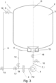
- the representation in 1 shows a first exemplary embodiment of a mixing device 1 according to the invention for producing a free-flowing product.
- the mixing device 1 comprises a mixing container 2 which is designed to be liquid-tight and/or gas-tight. At the top area, the mixing container includes a first inlet 5.
- the interior 3 of the mixing container is also equipped with an agitator, which in 1 is not shown to simplify the illustration.
- the agitator can preferably be rotated about an axis of rotation D, which is arranged vertically in the exemplary embodiment.
- the agitator may have one or more blades mounted for rotation about the axis of rotation.
- the agitator can comprise one or more scrapers which are set up to scrape off material adhering to an inner wall of the mixing container 2 during a movement about the axis of rotation.
- the agitator can consist of several independent stirring elements.
- the agitator can be designed as a coaxial agitator, which comprises a scraping agitator and a conveying agitator that is driven independently of the scraping agitator.
- An outlet 15 is provided in the bottom area of the mixing container 2 , via which the product can be drawn off from the mixing container 2 .
- a homogenization device 4 is arranged on the mixing container 2, here inside the mixing container 2, via which the product can be finely homogenized.
- the homogenization device 4 can be a rotor-stator homogenizer, for example.
- the mixing device 1 comprises a conveying device 7 with a suction side 7.1 and a pressure side 7.2, the suction side 7.1 being connected to the outlet 15 of the mixing container 2, in particular to the homogenization device 4, and the pressure side 7.2 being optionally connected to the first inlet 5 of the mixing container 2 is connectable. Also provided between the outlet 15 and the suction side of the conveying device 7 is an adding device 10 for adding an additive, in particular a powdered additive.
- the conveyor device 7 is arranged outside of the mixing container 2 and, as in 1 shown, be integrated into a base section of the mixing device 1.
- the conveying device 7 comprises a drive shaft 9 designed as a hollow shaft, which is arranged concentrically to a drive shaft 8 of the homogenization device 4 . This enables a space-saving arrangement to be made possible.
- the delivery device 7 is preferably designed as a displacement pump.
- An embodiment of the conveying device 7 as a rotary piston pump or membrane pump or sinusoidal pump or eccentric screw pump is particularly preferred, since in this way a particularly gentle, low-shear conveying of the product can be made possible.
- the mixing device 1 also includes a first return line 11 between the pressure side 7.2 of the conveying device 7 and the first inlet 5 of the mixing container 2.
- the product conveyed by the conveying device 7 can be returned to the mixing container via this return line 11. Since the addition of powdery additives takes place on the suction side 7.1 of the conveyor device 7 and the additives can already mix in the return line 11, dust formation when introducing the product into the mixing container 2 can be effectively reduced or prevented.
- a product output 13 is also provided on the pressure side 7.2 of the conveyor device 7 .
- the product outlet 13 is designed as a valve that can be opened selectively in order to withdraw the product from the mixing device 1. Here the product can be conveyed through the conveying device 7 .
- the mixing device 1 also includes a second return line 12 between the pressure side of the conveyor device 7 and a second inlet 6 of the mixing container 1, which is arranged in the region of the homogenization device 4.
- the second return line 12, in cooperation with the second inlet 6, enables small amounts of the product to be circulated.
- the second inlet 6 opens into a channel which runs vertically on the inner wall of the container and which ends in an inlet region of the homogenization device 4 .
- the second inlet 6 is arranged in a lower area of the mixing container 1 , here in a lower third of a filling volume of the mixing container 1 , more precisely in a bottom area of the mixing container 1 .
- the mixing device 1 comprises a switching device, which is formed from two valves 17, 19 connected to the pressure side 7.2 of the conveying device 7.
- the pressure side 7 . 2 of the conveying device 7 can be optionally connected to the first return line 11 or the second return line 12 by the switching device 17 , 19 .
- the mixing container 2 comprises a further addition device 20 in the area of its outlet 5, here in the inlet area of the homogenization device 4.
- a second embodiment of a mixing device 1 according to the invention is shown.
- the mixing device 1 according to the second embodiment essentially corresponds to the mixing device according to the first embodiment, with the difference that in the second embodiment, two separate, non-concentrically arranged drive shafts 8, 9 are provided for driving the homogenization device 4 and the conveyor device 7.
- the drive shaft 8 of the homogenization device 4 can be rotated about a vertical axis of rotation which is parallel to the axis of rotation D of the agitator, which is not shown, and is in particular identical to this axis of rotation D.
- the drive axis 9 of the conveying device 7 is arranged at an angle relative to the drive axis 8 of the homogenization device 4, preferably at an angle in the range from 15 to 45°, for example by 30°.
- a method can be used in which a product contained within the mixing container 2 is homogenized by the homogenization device 4 arranged in the area of the outlet 15 of the mixing container 2, with the conveyor device 7 connected to the outlet 15 of the mixing container 2 discharging the product the outlet 15 sucks, and through an arranged between the outlet 15 of the mixing container 2 and the conveyor device 7 adding device 10, in particular powdered additive is added.
- a pressure in the range from 0.95 bar to 1.05 bar is set in the mixing container 2, in particular normal pressure, for example 1.01 bar. In this respect it is not necessary to generate a negative pressure or a vacuum in the mixing container 2 .
- the mixing tank can be vented to the ambient pressure without differential pressure.
- the product can be mixed with the additive in the mixing container 2 by the agitator of the mixing device 1.
- the conveying device 7 preferably conveys a mixture of the product and the additive through a first return line 11 to the first inlet 5 of the mixing container 2.
- the product can optionally be returned to the mixing container 2 through the second return line 12 .
- the conveyor device 7 conveys the product with the additive to the second inlet 6 of the mixing container 2 in the area of the homogenization device 4.
- the product can be drawn off from the mixing device 1 via the product outlet 13 .
- a bypass not shown in the drawings can be activated, which creates a direct connection between the outlet 15 of the mixing container and the pressure side 7.2 of the conveying device 7.
- the product can then be conveyed solely by the conveying capacity of the homogenization device 4, for example into the first return line 11, the second return line 12 or the product outlet 13.
- a third embodiment of a mixing device 1 according to the invention is shown.
- the mixing device 1 according to the third exemplary embodiment essentially corresponds to the mixing device according to the first exemplary embodiment, with the difference that the homogenization device 4 is arranged on the pressure side of the conveyor device 7 in the third exemplary embodiment.
- the homogenization device is not located in the area of the outlet 15 of the mixing container 2 , but is arranged externally of the mixing container 2 .
- the homogenization device 4 can be a rotor-stator homogenizer, for example.
- the mixing device 1 comprises a mixing container 2 which is designed to be liquid-tight and/or gas-tight.
- the mixing container includes a first inlet 5.
- the interior 3 of the mixing container is also equipped with an agitator, which is not shown to simplify the illustration and can be designed as described in connection with the first exemplary embodiment.
- An outlet 15 is provided in the bottom area of the mixing container 2 , via which the product can be drawn off from the mixing container 2 .
- an adding device 10 for adding an additive, in particular a powdered additive. Furthermore, between the outlet 15 and the addition device 10 arranged flow control device 16 is arranged.
- the conveying device 7 can be arranged outside of the mixing container 2 or in the area of the outlet 5 , for example flanged to the outlet 5 .
- the delivery device 7 is preferably designed as a displacement pump.
- An embodiment of the conveying device 7 as a rotary piston pump or membrane pump or sinusoidal pump or eccentric screw pump is particularly preferred, since in this way a particularly gentle, low-shear conveying of the product can be made possible.
- the mixing device 1 also includes a first return line 11 between the homogenization device 4 and the first inlet 5 of the mixing container 2.
- the product conveyed by the conveyor device 7 can be returned to the mixing container via this return line 11. Since the addition of powdery additives takes place on the suction side 7.1 of the conveyor device 7 and the additives can already mix in the return line 11, dust formation when introducing the product into the mixing container 2 can be effectively reduced or prevented.
- a product output 13 is also provided on the pressure side of the homogenization device 4 .
- the product outlet 13 is designed as a valve that can be opened selectively in order to withdraw the product from the mixing device 1. Here the product can be conveyed through the conveying device 7 .
- the mixing device 1 also includes a second return line 12 between the homogenization device 4 and a second inlet 6 of the mixing container 1, which is in a lower area of the mixing container 1, here in a lower third of a filling volume of the mixing container 1, more precisely in a bottom area of the mixing container 1 , is arranged.
- the second return line 12, in cooperation with the second inlet 6, enables small amounts of the product to be circulated.
- a method can be used in which a product contained within the mixing container 2 is homogenized by the homogenization device 4 arranged outside the mixing container 2, with the conveying device 7 connected to the outlet 15 of the mixing container 2 sucking the product out of the outlet 15 , and by means of an addition device 10 arranged between the outlet 15 of the mixing container 2 and the conveying device 7, an additive, in particular in powder form, is added.
- a pressure in the range from 0.95 bar to 1.05 bar is set in the mixing container 2, in particular normal pressure, for example 1.01 bar. In this respect, it is not necessary to generate a negative pressure or vacuum in the mixing container.
- the product can be mixed with the additive in the mixing container 2 by the agitator of the mixing device 1.
- the mixing device 1 comprises a switching device, which is formed from two valves 17, 19 connected to the homogenization device 4.
- the switching device 17, 19 allows the homogenization device 4 to be connected either to the first return line 11 or to the second return line 12.
- a small amount of product-ingredient mixture can be started in the mixing tank 2, with the second recycle line 12 being used to recycle the product-ingredient mixture.
- the valve 17 of the first return line 11 is switched impermeable and the valve 19 of the second return line 12 is switched permeable. It can then be added through the addition device 10, which is sucked in by the conveyor 7 additive material.
- the product-additive mixture can be returned to the mixing tank 2 via the first return line 11, with the valve 17 of the first return line 11 being permeable and the valve 19 of the second return line 12 being impermeable is switched.
- the product can be drawn off from the mixing device 1 via the product outlet 13 .
Landscapes
- Chemical & Material Sciences (AREA)
- Chemical Kinetics & Catalysis (AREA)
- Dispersion Chemistry (AREA)
- Processing And Handling Of Plastics And Other Materials For Molding In General (AREA)
Abstract
Die vorliegende Erfindung betrifft eine Mischeinrichtung (1) zur Herstellung eines fließfähigen Produkts mit einem Mischbehälter (2), der einen ersten Einlass (5) und einen Auslass (15) aufweist, und einer Homogenisierungsvorrichtung (4), mit einer Fördervorrichtung (7) mit einer Saugseite (7.1) und einer Druckseite (7.2), wobei die Saugseite (7.1) mit dem Auslass (15) des Mischbehälters (2) verbunden ist und die Druckseite (7.2) wahlweise mit dem ersten Einlass (5) des Mischbehälters (2) verbindbar ist, und mit einer Zugabevorrichtung (10) zur Zugabe eines, insbesondere pulverförmigen, Zugabestoffs, die zwischen dem Auslass (15) des Mischbehälters (2) und der Saugseite (7.1) der Fördervorrichtung (7) angeordnet ist.

Description
Die vorliegende Erfindung betrifft eine Mischeinrichtung zur Herstellung eines fließfähigen Produkts mit einem Mischbehälter, der einen ersten Einlass und einen Auslass aufweist, wobei an dem Mischbehälter im Bereich des Auslasses eine Homogenisierungsvorrichtung angeordnet ist. Ferner betrifft die Erfindung ein Verfahren zum Betrieb einer Mischeinrichtung, die einen Mischbehälter mit einem ersten Einlass und einem Auslass aufweist, wobei ein innerhalb des Mischbehälters enthaltenes Produkt durch eine im Bereich des Auslasses des Mischbehälters angeordnete Homogenisierungsvorrichtung homogenisiert wird.The present invention relates to a mixing device for producing a free-flowing product with a mixing container that has a first inlet and an outlet, with a homogenization device being arranged on the mixing container in the area of the outlet. The invention also relates to a method for operating a mixing device which has a mixing container with a first inlet and an outlet, a product contained within the mixing container being homogenized by a homogenization device arranged in the area of the outlet of the mixing container.
Eine derartige Mischeinrichtung mit einer Homogenisierungsvorrichtung ist beispielsweise aus der
Die Aufgabe der vorliegenden Erfindung ist es, den Produktverlust sowie die Staub- und Schaumbildung im Mischbehälter zu reduzieren.The object of the present invention is to reduce the loss of product as well as the formation of dust and foam in the mixing tank.
Zur Lösung der Aufgabe wird eine Mischeinrichtung zur Herstellung eines fließfähigen Produkts mit einem Mischbehälter vorgeschlagen, der einen ersten Einlass und einen Auslass aufweist, und einer Homogenisierungsvorrichtung, wobei die Mischeinrichtung eine Fördervorrichtung mit einer Saugseite und einer Druckseite umfasst, wobei die Saugseite mit dem Auslass verbunden ist und die Druckseite wahlweise mit dem ersten Einlass des Mischbehälters verbindbar ist, und eine Zugabevorrichtung zur Zugabe eines, insbesondere pulverförmigen, Zugabestoffs, die zwischen dem Auslass des Mischbehälters und der Saugseite der Fördervorrichtung angeordnet ist.To solve the problem, a mixing device for producing a free-flowing product is proposed with a mixing container that has a first inlet and an outlet, and a homogenization device, the mixing device comprising a conveyor device with a suction side and a pressure side, the suction side being connected to the outlet and the pressure side can optionally be connected to the first inlet of the mixing container, and an addition device for adding an additive, in particular a powder, which is arranged between the outlet of the mixing container and the suction side of the conveying device.
Bei der erfindungsgemäßen Mischeinrichtung ist zusätzlich zu der Homogenisierungsvorrichtung eine Fördervorrichtung vorgesehen. Durch die Fördervorrichtung kann die Förderleistung unabhängig von der Homogenisierungsleistung der Homogenisierungsvorrichtung eingestellt werden, so dass es möglich ist, die Förderleistung zu erhöhen ohne das Gemisch einer erhöhten Scherung in der Homogenisierungsvorrichtung auszusetzen. Die Zugabevorrichtung zur Zugabe des Zugabestoffs ist erfindungsgemäß zwischen dem Auslass des Mischbehälters und der Fördervorrichtung vorgesehen. Die Fördervorrichtung kann den Zugabestoff zusammen mit dem aus dem Auslass des Mischbehälters bzw. der Homogenisierungsvorrichtung austretenden Gemisch ansaugen und beispielsweise über den ersten Einlass zurück in den Mischbehälter fördern. Bei diesem Vorgehen kann eine Staub- und Schaumentwicklung in dem Mischbehälter stark reduziert werden. Etwaige zusammen mit dem Zugabestoff angesaugte Luft wird durch die Fördervorrichtung ebenfalls in den Mischbehälter gefördert. Die Luft kann sich beim Einbringen des Gemisches in den Mischbehälter oberhalb des Produkts in dem Mischbehälter absetzen, während der Zugabestoff in dem Produkt verbleibt. Es ist nicht erforderlich, einen Unterdruck im Mischbehälter zu erzeugen, um den Zugabestoff einzusaugen. Ein unerwünschter Produktverlust durch das Erzeugen eines Unterdrucks kann verhindert werden. Durch die Homogenisierungsvorrichtung kann das Produkt dann weiter homogenisiert werden.In the mixing device according to the invention, a conveying device is provided in addition to the homogenization device. With the conveying device, the conveying capacity can be set independently of the homogenization capacity of the homogenization device, so that it is possible to increase the conveying capacity without subjecting the mixture to increased shearing in the homogenization device. According to the invention, the addition device for adding the additive is provided between the outlet of the mixing container and the conveying device. The conveying device can suck in the additive together with the mixture emerging from the outlet of the mixing container or the homogenization device and, for example, convey it back into the mixing container via the first inlet. With this procedure, the development of dust and foam in the mixing container can be greatly reduced. Any air sucked in together with the additive is also conveyed into the mixing container by the conveying device. When the mixture is introduced into the mixing tank, the air can settle above the product in the mixing tank, while the additive remains in the product. It is not necessary to create a vacuum in the mixing tank to suck in the additive. An undesired loss of product due to the creation of a negative pressure can be prevented. The product can then be further homogenized by the homogenization device.
Gemäß einer vorteilhaften Ausgestaltung der Erfindung ist die Homogenisierungsvorrichtung an dem Mischbehälter im Bereich des Auslasses angeordnet. Bei einer derartigen Ausgestaltung ist die Homogenisierungsvorrichtung auf der Saugseite der Fördereinrichtung angeordnet, so dass durch das von der Homogenisierungsvorrichtung homogenisierte Produkt von der Fördereinrichtung angesaugt werden kann. Die Homogenisierungsvorrichtung kann im Bereich des Auslasses innerhalb des Mischbehälters oder außerhalb des Mischbehälters angeordnet sein. Weiter alternativ ist es möglich, dass die Homogenisierungsvorrichtung im Bereich des Auslasses teilweise innerhalb und teilweise außerhalb des Mischbehälters angeordnet ist.According to an advantageous embodiment of the invention, the homogenization device is arranged on the mixing container in the area of the outlet. In such a configuration, the homogenization device is arranged on the suction side of the conveyor device, so that the product that has been homogenized by the homogenization device can be sucked in by the conveyor device. The homogenization device can be arranged in the area of the outlet inside the mixing container or outside of the mixing container. As a further alternative, it is possible for the homogenization device in the area of the outlet to be arranged partially inside and partially outside the mixing container.
Der Auslass des Mischbehälters ist bevorzugt in einem Bodenbereich des Mischbehälters bzw. an einer Unterseite des Mischbehälters angeordnet.The outlet of the mixing container is preferably arranged in a bottom area of the mixing container or on an underside of the mixing container.
Gemäß einer vorteilhaften Ausgestaltung der Erfindung umfasst die Mischeinrichtung eine erste Rückführleitung zwischen der Druckseite der Fördervorrichtung und dem ersten Einlass des Mischbehälters. Über die Rückführleitung kann das Produkt sowie ggf. zu dem Produkt zugegebenes Zugabestoff zurück in den Mischbehälter gefördert werden. Insofern wird über die erste Rückführleitung eine mischbehälterexterne Umwälzung des Produkts ermöglicht. Optional kann in der ersten Rückführleitung eine weitere Zugabevorrichtung zur Zugabe von, insbesondere pulverförmigem, Zugabestoff vorgesehen sein. In der Rückführleitung kann mindestens ein Ventil vorgesehen sein. Über das Ventil kann der Volumenstrom in der Rückführleitung eingestellt werden. Wahlweise kann der Volumenstrom durch die Rückführleitung auf Null gesetzt werden, um die Rückführung des Produkts in den Mischbehälter vollständig zu unterbinden. Letzteres kann beispielsweise dann erforderlich sein, wenn das Produkt aus dem Mischbehälter abgezogen werden soll.According to an advantageous embodiment of the invention, the mixing device includes a first return line between the pressure side of the conveying device and the first inlet of the mixing container. The product and any additives added to the product can be conveyed back into the mixing container via the return line. In this respect, circulation of the product outside the mixing container is made possible via the first return line. Optionally, a further addition device can be provided in the first return line for adding, in particular powdered, additive. At least one valve can be provided in the return line. The volume flow in the return line can be adjusted via the valve. Optionally, the volume flow through the return line can be set to zero in order to completely prevent the return of the product to the mixing tank. The latter can be necessary, for example, when the product is to be drawn off from the mixing container.
Gemäß einer vorteilhaften Ausgestaltung der Erfindung umfasst die Mischeinrichtung einen zweiten Einlass des Mischbehälters im Bereich der Homogenisierungsvorrichtung. Über den zweiten Einlass kann optional die Zugabe eines Zugabestoffs erfolgen. Der zweite Einlass kann beispielsweise in einen Einlassbereich der Homogenisierungsvorrichtung münden.According to an advantageous embodiment of the invention, the mixing device includes a second inlet of the mixing container in the area of the homogenization device. An additive can optionally be added via the second inlet. The second inlet can, for example, open into an inlet area of the homogenization device.
Gemäß einer vorteilhaften Ausgestaltung der Erfindung umfasst die Mischeinrichtung eine zweite Rückführleitung zwischen der Druckseite der Fördervorrichtung und dem zweiten Einlass des Mischbehälters. Bei einer derartigen Ausgestaltung ist es möglich, das Produkt sowie ggf. zu dem Produkt zugegebenen Zugabestoff zurück in den Mischbehälter zu fördern. Die Rückführung im Bereich der Homogenisierungsvorrichtung ist insbesondere dann von Vorteil, wenn geringe Produktmengen gemischt werden, welche den Mischbehälter nur zu einem geringen Teil füllen. In der zweiten Rückführleitung kann mindestens ein Ventil vorgesehen sein. Über das Ventil kann der Volumenstrom in der zweiten Rückführleitung eingestellt werden. Wahlweise kann der Volumenstrom durch die Rückführleitung auf Null gesetzt werden, um die Rückführung des Produkts in den Mischbehälter vollständig zu unterbinden. Letzteres kann beispielsweise dann erforderlich sein, wenn das Produkt aus dem Mischbehälter abgezogen werden soll.According to an advantageous embodiment of the invention, the mixing device includes a second return line between the pressure side of the conveying device and the second inlet of the mixing container. With such a configuration, it is possible to convey the product and any additives added to the product back into the mixing container. The recirculation in the area of the homogenization device is particularly advantageous when small quantities of product are mixed, which only fill the mixing container fill a small part. At least one valve can be provided in the second return line. The volume flow in the second return line can be adjusted via the valve. Optionally, the volume flow through the return line can be set to zero in order to completely prevent the return of the product to the mixing tank. The latter can be necessary, for example, if the product is to be drawn off from the mixing container.
Als besonders vorteilhaft hat sich eine Ausgestaltung erwiesen, bei welcher die Mischeinrichtung sowohl die vorstehend beschriebene erste Rückführleitung als auch die vorstehend beschriebene zweite Rückführleitung und eine Umschalteinrichtung aufweist, durch welche die Druckseite der Fördereinrichtung wahlweise mit der ersten Rückführleitung oder der zweiten Rückführleitung verbindbar ist. Eine derartige Ausgestaltung bietet den Vorteil, dass in einem Prozess, der mit geringen Produktmengen beginnt, zunächst eine Rückführung des Produkts in den Mischbehälter über die zweite Rückführleitung erfolgen kann und zu einem späteren Zeitpunkt des Prozesses, beispielsweise durch Zugaben, mit einer größeren Produktmenge gearbeitet werden kann, wobei das Produkt dann über die erste Rückführleitung in den Mischbehälter zurückgeführt wird. Insofern kann durch eine solche Ausgestaltung eine größere Flexibilität bei der Nutzung des Mischeinrichtung für unterschiedliche Produktmengen ermöglicht werden.A configuration has proven to be particularly advantageous in which the mixing device has both the first return line described above and the second return line described above and a switching device, by means of which the pressure side of the conveyor device can be connected to the first return line or the second return line as desired. Such a configuration offers the advantage that in a process that begins with small amounts of product, the product can first be returned to the mixing container via the second return line and at a later point in time in the process, for example by additions, a larger amount of product can be used can, the product then being returned to the mixing vessel via the first return line. In this respect, such a design allows greater flexibility when using the mixing device for different amounts of product.
Gemäß einer vorteilhaften Ausgestaltung der Erfindung umfasst die Mischeinrichtung eine mit der Druckseite der Fördervorrichtung verbundenen Produktausgabe. Hierdurch wird es möglich, dass die Fördervorrichtung das Produkt nach abgeschlossenem Mischprozess aus der Mischeinrichtung heraus fördern kann. Die Produktausgabe kann wahlweise geöffnet oder geschlossen werden, so dass das Produkt wahlweise aus der Mischeinrichtung ausgetragen werden kann.According to an advantageous embodiment of the invention, the mixing device includes a product outlet connected to the pressure side of the conveyor device. This makes it possible for the conveying device to be able to convey the product out of the mixing device after the mixing process has ended. The product output can either be opened or closed so that the product can be discharged from the mixing device as required.
Gemäß einer vorteilhaften Ausgestaltung der Erfindung ist die Homogenisierungsvorrichtung auf der Druckseite der Fördereinrichtung angeordnet. Insofern kann das aus dem Auslass des Mischbehälters angesaugte Produkt unter Druck in die Homogenisierungsvorrichtung gefördert werden. Die Homogenisierungsvorrichtung kann außerhalb des Mischbehälters angeordnet sein. Bei einer derartigen Ausgestaltung mit Homogenisierungsvorrichtung auf der Druckseite der Fördereinrichtung kann die Fördereinrichtung im Bereich des Auslasses des Mischbehälters angeordnet sein, insbesondere an dem Auslass angeflanscht sein. Ein direktes Anflanschen erlaubt es, mit geringen Mengen an Produkt im Mischbehälter zu arbeiten.According to an advantageous embodiment of the invention, the homogenization device is arranged on the pressure side of the conveying device. In this respect, the product sucked in from the outlet of the mixing container can be conveyed under pressure into the homogenization device. The homogenization device can be arranged outside the mixing container. In such an embodiment with a homogenization device on the pressure side of the conveying device, the conveying device can be arranged in the area of the outlet of the mixing container, in particular flanged to the outlet. Direct flanging allows you to work with small amounts of product in the mixing tank.
Gemäß einer vorteilhaften Ausgestaltung der Erfindung umfasst die Mischeinrichtung eine zwischen dem Auslass des Mischbehälters und der Zugabevorrichtung angeordnete Durchflussregulierungsvorrichtung. Die Durchflussregulierungsvorrichtung kann beispielsweise als Ventil, insbesondere Drosselventil, ausgestaltet sein. Alternativ kann die Durchflussregulierungsvorrichtung als Drehscheibe ausgebildet sein, die beispielsweise im Bereich des Auslasses des Mischbehälters und/oder im Zulauf der Fördereinrichtung angeordnet ist. Durch die Durchflussregulierungsvorrichtung kann die Saugleistung zum Ansaugen von Produkt aus dem Mischbehälter reduziert und dadurch die Saugleistung zum Ansaugen des an der Zugabevorrichtung bereitgestellten Zugabestoffs vergrößert werden.According to an advantageous embodiment of the invention, the mixing device comprises a flow control device arranged between the outlet of the mixing container and the addition device. The flow control device can be designed, for example, as a valve, in particular a throttle valve. Alternatively, the flow control device can be designed as a rotary disk, which is arranged, for example, in the area of the outlet of the mixing container and/or in the inlet of the conveying device. The flow control device can reduce the suction power for sucking in product from the mixing container and thereby increase the suction power for sucking in the additive provided at the adding device.
Gemäß einer vorteilhaften Ausgestaltung der Erfindung umfasst die Mischeinrichtung eine erste Rückführleitung zwischen der Homogenisierungsvorrichtung, insbesondere einem Auslass der Homogenisierungsvorrichtung, und dem ersten Einlass des Mischbehälters. Über die Rückführleitung kann das Produkt sowie ggf. zu dem Produkt zugegebenes Zugabestoff zurück in den Mischbehälter gefördert werden. Insofern wird über die erste Rückführleitung eine mischbehälterexterne Umwälzung des Produkts ermöglicht. Optional kann in der ersten Rückführleitung eine weitere Zugabevorrichtung zur Zugabe von, insbesondere pulverförmigem, Zugabestoff vorgesehen sein. In der Rückführleitung kann mindestens ein Ventil vorgesehen sein. Über das Ventil kann der Volumenstrom in der Rückführleitung eingestellt werden. Wahlweise kann der Volumenstrom durch die Rückführleitung auf Null gesetzt werden, um die Rückführung des Produkts in den Mischbehälter vollständig zu unterbinden. Letzteres kann beispielsweise dann erforderlich sein, wenn das Produkt aus dem Mischbehälter abgezogen werden soll.According to an advantageous embodiment of the invention, the mixing device includes a first return line between the homogenization device, in particular an outlet of the homogenization device, and the first inlet of the mixing container. The product and any additives added to the product can be conveyed back into the mixing container via the return line. In this respect, circulation of the product outside the mixing container is made possible via the first return line. Optionally, a further addition device can be provided in the first return line for adding, in particular powdered, additive. At least one valve can be provided in the return line. The volume flow in the return line can be adjusted via the valve. Optionally, the volume flow through the return line can be set to zero in order to completely prevent the return of the product to the mixing tank. The latter can be necessary, for example, if the product is to be drawn off from the mixing container.
Gemäß einer vorteilhaften Ausgestaltung der Erfindung umfasst die Mischeinrichtung einen zweiten Einlass des Mischbehälters in einem unteren Bereich des Mischbehälters, insbesondere in einem unteren Drittel eines Füllvolumens des Mischbehälters, bevorzugt in einem Bodenbereich des Mischbehälters. Besonders bevorzugt sind sowohl der zweite Einlass als auch der Auslass im unteren Bereich des Mischbehälters angeordnet, insbesondere in einem unteren Drittel eines Füllvolumens des Mischbehälters, bevorzugt in einem Bodenbereich des Mischbehälters. Über den zweiten Einlass kann optional die Zugabe eines Zugabestoffs erfolgen.According to an advantageous embodiment of the invention, the mixing device comprises a second inlet of the mixing container in a lower area of the mixing container, in particular in a lower third of a filling volume of the mixing container, preferably in a bottom area of the mixing container. Both the second inlet and the outlet are particularly preferably arranged in the lower area of the mixing container, in particular in a lower third of a filling volume of the mixing container, preferably in a bottom area of the mixing container. An additive can optionally be added via the second inlet.
Gemäß einer vorteilhaften Ausgestaltung der Erfindung umfasst die Mischeinrichtung eine zweite Rückführleitung zwischen der Homogenisierungsvorrichtung, insbesondere einem Auslass der Homogenisierungsvorrichtung, und dem zweiten Einlass des Mischbehälters. Bei einer derartigen Ausgestaltung ist es möglich, das Produkt sowie ggf. zu dem Produkt zugegebenen Zugabestoff zurück in den Mischbehälter zu fördern. Die Rückführung im Bereich des Auslasses ist insbesondere dann von Vorteil, wenn geringe Produktmengen gemischt werden, welche den Mischbehälter nur zu einem geringen Teil füllen. In der zweiten Rückführleitung kann mindestens ein Ventil vorgesehen sein. Über das Ventil kann der Volumenstrom in der zweiten Rückführleitung eingestellt werden. Wahlweise kann der Volumenstrom durch die Rückführleitung auf Null gesetzt werden, um die Rückführung des Produkts in den Mischbehälter vollständig zu unterbinden. Letzteres kann beispielsweise dann erforderlich sein, wenn das Produkt aus dem Mischbehälter abgezogen werden soll.According to an advantageous embodiment of the invention, the mixing device comprises a second return line between the homogenization device, in particular an outlet of the homogenization device, and the second inlet of the mixing container. With such a configuration, it is possible to use the product and possibly the product to convey the added additive back into the mixing container. The recirculation in the area of the outlet is particularly advantageous when small quantities of product are mixed, which fill the mixing container only to a small extent. At least one valve can be provided in the second return line. The volume flow in the second return line can be adjusted via the valve. Optionally, the volume flow through the return line can be set to zero in order to completely prevent the return of the product to the mixing tank. The latter can be necessary, for example, if the product is to be drawn off from the mixing container.
Als besonders vorteilhaft hat sich eine Ausgestaltung erwiesen, bei welcher die Mischeinrichtung sowohl die vorstehend beschriebene erste Rückführleitung als auch die vorstehend beschriebene zweite Rückführleitung und eine Umschalteinrichtung aufweist, durch welche die Homogenisierungsvorrichtung wahlweise mit der ersten Rückführleitung oder der zweiten Rückführleitung verbindbar ist. Eine derartige Ausgestaltung bietet den Vorteil, dass in einem Prozess, der mit geringen Produktmengen beginnt, zunächst eine Rückführung des Produkts in den Mischbehälter über die zweite Rückführleitung erfolgen kann und zu einem späteren Zeitpunkt des Prozesses, beispielsweise durch Zugaben, mit einer größeren Produktmenge gearbeitet werden kann, wobei das Produkt dann über die erste Rückführleitung in den Mischbehälter zurückgeführt wird. Insofern kann durch eine solche Ausgestaltung eine größere Flexibilität bei der Nutzung des Mischeinrichtung für unterschiedliche Produktmengen ermöglicht werden.An embodiment has proven to be particularly advantageous in which the mixing device has both the first return line described above and the second return line described above and a switchover device by which the homogenization device can be connected either to the first return line or to the second return line. Such a configuration offers the advantage that in a process that begins with small amounts of product, the product can first be returned to the mixing container via the second return line and at a later point in time in the process, for example by additions, a larger amount of product can be used can, the product then being returned to the mixing vessel via the first return line. In this respect, such a design allows greater flexibility when using the mixing device for different amounts of product.
Gemäß einer vorteilhaften Ausgestaltung der Erfindung umfasst die Mischeinrichtung eine mit der Homogenisierungsvorrichtung verbundenen Produktausgabe. Hierdurch wird es möglich, dass das Produkt nach Abgabe durch die Homogenisierungsvorrichtung aus der Mischeinrichtung entnommen werden kann. Die Produktausgabe kann wahlweise geöffnet oder geschlossen werden, so dass das Produkt wahlweise aus der Mischeinrichtung ausgetragen werden kann.According to an advantageous embodiment of the invention, the mixing device includes a product outlet connected to the homogenization device. This makes it possible for the product to be removed from the mixing device after it has been dispensed by the homogenization device. The product output can either be opened or closed so that the product can be discharged from the mixing device as required.
Gemäß einer vorteilhaften Ausgestaltung der Erfindung umfasst die Mischeinrichtung ein innerhalb des Mischbehälters angeordnetes Rührwerk. Das Rührwerk kann um eine Drehachse des Mischbehälters drehbar vorgesehen sein, insbesondere eine vertikale Drehachse. Bevorzugt umfasst das Rührwerk einen oder mehrere Abstreifer zum Abstreifen von an einer Innenwandung des Mischbehälters anhaftenden Produkts.According to an advantageous embodiment of the invention, the mixing device comprises an agitator arranged inside the mixing container. The agitator can be provided so as to be rotatable about an axis of rotation of the mixing container, in particular a vertical axis of rotation. The agitator preferably comprises one or more scrapers for scraping off product adhering to an inner wall of the mixing container.
Gemäß einer vorteilhaften Ausgestaltung der Erfindung ist vorgesehen, dass die Homogenisierungsvorrichtung als Rotor-Stator-Homogenisierer ausgebildet ist. Rotor-Stator-Homogenisierer umfassen typischerweise einen Rotor und einen Stator, die zueinander konzentrische Verzahnungen aufweisen. Der Rotor kann das fließfähige Produkt radial nach außen Richtung des Stators fördern. Der Stator umfasst typischerweise feststehende Elemente, beispielsweise Zähne, die durch Lücken voneinander getrennt sind. Das radial nach außen geförderte Produkt wird beim Durchströmen der Lücken durch Scherung fein homogenisiert. Optional kann vorgesehen sein, dass der Stator angetrieben ist und gleichläufig oder gegenläufig mit dem Rotor dreht. Die Homogenisierungsvorrichtung kann mit mehreren Rotor- und/oder Stator-Stufen ausgestaltet sein, beispielsweise in radialer Anordnung oder in axialer Anordnung.According to an advantageous embodiment of the invention, it is provided that the homogenization device is designed as a rotor-stator homogenizer. Rotor-stator homogenizers typically include a rotor and a stator which have concentric toothings. The rotor can convey the free-flowing product radially outwards in the direction of the stator. The stator typically includes fixed elements, such as teeth, separated by gaps. The product, which is conveyed radially outwards, is finely homogenized by shearing as it flows through the gaps. It can optionally be provided that the stator is driven and rotates in the same direction or in opposite directions with the rotor. The homogenization device can be designed with a plurality of rotor and/or stator stages, for example in a radial arrangement or in an axial arrangement.
Gemäß einer vorteilhaften Ausgestaltung der Erfindung ist vorgesehen, dass die Fördervorrichtung eine Verdrängerpumpe ist. Die Verwendung einer Verdrängerpumpe bietet den Vorteil, dass eine hohe Saugkraft zum Ansaugen des Produkts und ggf. des Zugabestoffs bereitgestellt werden kann.According to an advantageous embodiment of the invention, it is provided that the delivery device is a displacement pump. The use of a displacement pump offers the advantage that a high suction force can be provided for sucking in the product and, if necessary, the additive.
Gemäß einer besonders vorteilhaften Ausgestaltung der Erfindung ist vorgesehen, dass die Fördervorrichtung eine Drehkolbenpumpe oder eine Membranpumpe oder eine Sinuspumpe oder eine Exzenterschneckenpumpe ist. Die genannten Pumpen bieten jeweils eine hohe Saugleistung bei geringer Scherung des geförderten Produkts und geringen in das Produkt eingeleiteten Vibrationen. Es kann daher eine besonders produktschonende Förderung des Produkts ermöglicht werden.According to a particularly advantageous embodiment of the invention, it is provided that the delivery device is a rotary piston pump or a diaphragm pump or a sinusoidal pump or an eccentric screw pump. The pumps mentioned each offer a high suction power with low shearing of the conveyed product and low vibrations introduced into the product. A particularly product-friendly conveyance of the product can therefore be made possible.
Gemäß einer vorteilhaften Ausgestaltung der Erfindung ist vorgesehen, dass die Fördervorrichtung eine Hohlwelle aufweist, die konzentrisch zu einer Antriebswelle der Homogenisierungsvorrichtung angeordnet ist. Eine solche Ausgestaltung bietet den Vorteil, dass der Rotor der Homogenisierungsvorrichtung und der Rotor der Fördervorrichtung konzentrisch gelagert werden können. Es kann eine kompakte vibrationsarme Ausgestaltung ermöglicht werden. Zum Antrieb der Homogenisierungsvorrichtung und der Fördervorrichtung sind bevorzugt zwei separate Antriebe vorgesehen.According to an advantageous embodiment of the invention, it is provided that the conveying device has a hollow shaft which is arranged concentrically to a drive shaft of the homogenization device. Such a configuration offers the advantage that the rotor of the homogenization device and the rotor of the conveying device can be mounted concentrically. A compact, low-vibration design can be made possible. Two separate drives are preferably provided for driving the homogenization device and the conveying device.
Gemäß einer vorteilhaften Ausgestaltung der Erfindung ist vorgesehen, dass der Mischbehälter flüssigkeits- und/oder luftdicht geschlossen ausgebildet ist.According to an advantageous embodiment of the invention, it is provided that the mixing container is closed in a liquid-tight and/or air-tight manner.
Zur Lösung der eingangs genannten Aufgabe trägt ferner ein Verfahren zum Betrieb einer Mischeinrichtung bei, die einen Mischbehälter mit einem ersten Einlass und einem Auslass aufweist, wobei ein innerhalb des Mischbehälters enthaltenes Produkt durch eine Homogenisierungsvorrichtung homogenisiert wird, wobei eine mit dem Auslass des Mischbehälters verbundene Fördervorrichtung das Produkt aus dem Auslass saugt, und durch eine zwischen dem Auslass des Mischbehälters und der Fördervorrichtung angeordnete Zugabevorrichtung ein, insbesondere pulverförmiger, Zugabestoff zugegeben wird.A method for operating a mixing device, which has a mixing container with a first inlet and an outlet, also contributes to solving the task mentioned at the outset wherein a product contained within the mixing container is homogenized by a homogenization device, wherein a conveyor device connected to the outlet of the mixing container sucks the product out of the outlet, and an additive, in particular a powdered additive, by an addition device arranged between the outlet of the mixing container and the conveyor device is admitted.
Durch das Verfahren können dieselben Vorteile erreicht werden, die bereits im Zusammenhang mit der erfindungsgemäßen Mischeinrichtung beschrieben worden sind.The method can achieve the same advantages that have already been described in connection with the mixing device according to the invention.
Die Homogenisierungsvorrichtung kann an dem Mischbehälter im Bereich des Auslasses angeordnet sein. Die Homogenisierungsvorrichtung kann im Bereich des Auslasses innerhalb des Mischbehälters oder außerhalb des Mischbehälters angeordnet sein. Weiter alternativ ist es möglich, dass die Homogenisierungsvorrichtung im Bereich des Auslasses teilweise innerhalb und teilweise außerhalb des Mischbehälters angeordnet ist.The homogenization device can be arranged on the mixing container in the area of the outlet. The homogenization device can be arranged in the area of the outlet inside the mixing container or outside of the mixing container. As a further alternative, it is possible for the homogenization device in the area of the outlet to be arranged partially inside and partially outside the mixing container.
Alternativ kann die Homogenisierungsvorrichtung auf der Druckseite der Fördereinrichtung angeordnet sein.Alternatively, the homogenization device can be arranged on the pressure side of the conveying device.
Gemäß einer vorteilhaften Ausgestaltung des Verfahrens ist vorgesehen, dass in dem Mischbehälter ein Druck im Bereich von 0,95 bar bis 1,05 bar eingestellt wird, insbesondere Normaldruck oder Umgebungsdruck, beispielsweise 1,01 bar oder dass der Mischbehälter zum Umgebungsdruck differenzdruckfrei belüftet wird. Insofern ist es nicht erforderlich in dem Mischbehälter einen Unterdruck oder ein Vakuum zu erzeugen.According to an advantageous embodiment of the method, it is provided that a pressure in the range of 0.95 bar to 1.05 bar is set in the mixing container, in particular normal pressure or ambient pressure, for example 1.01 bar, or that the mixing container is ventilated without differential pressure compared to the ambient pressure. In this respect, it is not necessary to generate a negative pressure or a vacuum in the mixing container.
Gemäß einer vorteilhaften Ausgestaltung des Verfahrens ist vorgesehen, dass die Fördervorrichtung durch eine erste Rückführleitung eine Produkt-Zugabestoff-Mischung zu dem ersten Einlass des Mischbehälters fördert.According to an advantageous embodiment of the method, it is provided that the conveying device conveys a mixture of product and additives through a first return line to the first inlet of the mixing container.
Gemäß einer vorteilhaften Ausgestaltung des Verfahrens ist vorgesehen, dass die Fördervorrichtung durch eine zweite Rückführleitung eine Produkt-Zugabestoff-Mischung zu einem zweiten Einlass des Mischbehälters fördert, über welchen die Produkt-Zugabestoff-Mischung im Bereich des Auslasses, insbesondere im Bereich der Homogenisierungsvorrichtung, zugeführt wird.According to an advantageous embodiment of the method, it is provided that the conveying device conveys a product-additive mixture through a second return line to a second inlet of the mixing container, via which the product-additive mixture is fed in the area of the outlet, in particular in the area of the homogenization device becomes.
Gemäß einer vorteilhaften Ausgestaltung ist vorgesehen, dass in einem ersten Verfahrensschritt des Betriebs die Produkt-Zugabestoff-Mischung durch die zweite Rückführleitung zu dem zweiten Einlass gefördert wird und in einem dem ersten Verfahrensschritt nachfolgenden zweiten Verfahrensschritt des Betriebs die Produkt-Zugabestoff-Mischung durch die erste Rückführleitung zu dem ersten Einlass gefördert wird. Hierbei können im ersten Verfahrensschritt geringere Mengen der Produkt-Zugabestoff-Mischung gemischt und gefördert werden als im zweiten Verfahrensschritt.According to an advantageous embodiment, it is provided that in a first process step of the operation, the mixture of product and additives is fed through the second return line the second inlet is conveyed and in a second process step of the operation subsequent to the first process step the product-ingredient mixture is conveyed through the first return line to the first inlet. In this case, smaller amounts of the mixture of product and additives can be mixed and conveyed in the first process step than in the second process step.
Gemäß einer vorteilhaften Ausgestaltung des Verfahrens ist vorgesehen, dass das Produkt bzw. die Produkt-Zugabestoff-Mischung in dem Mischbehälter durch ein Rührwerk vermischt wird.According to an advantageous embodiment of the method, it is provided that the product or the mixture of product and additives is mixed in the mixing container by means of an agitator.
Bei dem Verfahren können auch die im Zusammenhang mit der erfindungsgemäßen Mischeinrichtung beschriebenen vorteilhaften Ausgestaltungen und Merkmale allein oder in Kombination Anwendung finden.The advantageous configurations and features described in connection with the mixing device according to the invention can also be used alone or in combination in the method.
Weitere Einzelheiten, Merkmale und Vorteile der Erfindung ergeben sich aus den Zeichnungen, sowie aus der nachfolgenden Beschreibung von bevorzugten Ausführungsformen anhand der Zeichnungen. Die Zeichnungen illustrieren dabei lediglich beispielhafte Ausführungsformen der Erfindung, welche den Erfindungsgedanken nicht einschränken.Further details, features and advantages of the invention result from the drawings and from the following description of preferred embodiments with reference to the drawings. The drawings only illustrate exemplary embodiments of the invention, which do not limit the inventive concept.
Die
Die
Die
In den verschiedenen Figuren sind gleiche Teile stets mit den gleichen Bezugszeichen versehen und werden daher in der Regel auch jeweils nur einmal benannt bzw. erwähnt.In the various figures, the same parts are always provided with the same reference symbols and are therefore usually named or mentioned only once.
Die Darstellung in
Im Bodenbereich des Mischbehälters 2 ist ein Auslass 15 vorgesehen, über welchen das Produkt aus dem Mischbehälter 2 abgezogen werden kann. Im Bereich des Auslasses 15 ist an dem Mischbehälter 2, hier innerhalb des Mischbehälters 2, eine Homogenisierungsvorrichtung 4 angeordnet, über welche das Produkt fein homogenisiert werde kann. Bei der Homogenisierungsvorrichtung 4 kann es sich beispielsweise um einen Rotor-Stator-Homogenisierer handeln.An
Um eine verbesserte Förderleistung und reduzierte Staub- und Schaumbildung im Mischbehälter 2 zu ermöglichen, ohne dass es erforderlich ist, in dem Mischbehälter 2 einen Unterdruck zu erzeugen, sind bei der Mischeinrichtung 1 besondere Vorkehrungen getroffen. So umfasst die Mischeinrichtung 1 eine Fördervorrichtung 7 mit einer Saugseite 7.1 und einer Druckseite 7.2, wobei die Saugseite 7.1 mit dem Auslass 15 des Mischbehälters 2, insbesondere mit der Homogenisierungsvorrichtung 4, verbunden ist und die Druckseite 7.2 wahlweise mit dem ersten Einlass 5 des Mischbehälters 2 verbindbar ist. Zwischen dem Auslass 15 und der Saugseite der Fördervorrichtung 7 ist ferner eine Zugabevorrichtung 10 zur Zugabe eines, insbesondere pulverförmigen, Zugabestoffs vorgesehen.Special precautions are taken in the
Die Fördervorrichtung 7 ist extern des Mischbehälters 2 angeordnet und kann, wie in
Bevorzugt ist die Fördervorrichtung 7 als Verdrängerpumpe ausgestaltet. Besonders bevorzugt ist eine Ausgestaltung der Fördervorrichtung 7 als Drehkolbenpumpe oder Membranpumpe oder Sinuspumpe oder Exzenterschneckenpumpe, da hierbei eine besonders produktschonende, scherarme Förderung des Produkts ermöglicht werden kann.The
Die Mischeinrichtung 1 umfasst ferner eine erste Rückführleitung 11 zwischen der Druckseite 7.2 der Fördervorrichtung 7 und dem ersten Einlass 5 des Mischbehälters 2. Über diese Rückführleitung 11 kann das von der Fördervorrichtung 7 geförderte Produkt in den Mischbehälter zurückgeführt werden. Da die Zugabe von pulverförmigen Zugabestoffen auf der Saugseite 7.1 der Fördervorrichtung 7 erfolgt und sich die Zugabestoffe bereits in der Rückführleitung 11 mischen können, kann eine Staubentwicklung beim Einleiten des Produkts in den Mischbehälter 2 wirksam reduziert bzw. verhindert werden.The
Auf der Druckseite 7.2 der Fördervorrichtung 7 ist ferner eine Produktausgabe 13 vorgesehen. Die Produktausgabe 13 ist als Ventil ausgestaltet, das wahlweise geöffnet werden kann, um da Produkt aus der Mischeinrichtung 1 abzuziehen. Hierbei kann das Produkt durch die Fördervorrichtung 7 gefördert werden.A
Die Mischeinrichtung 1 umfasst zudem ein zweite Rückführleitung 12 zwischen der Druckseite der Fördervorrichtung 7 und einem zweiten Einlass 6 des Mischbehälters 1, welcher im Bereich der Homogenisierungseinrichtung 4 angeordnet ist. Die zweite Rückführleitung 12 ermöglicht im Zusammenspiel mit dem zweiten Einlass 6 eine Umwälzung von geringen Mengen des Produkts. Bei dem Ausführungsbeispiel mündet der zweite Einlass 6 in einen vertikal an der Behälterinnenwand verlaufenden Kanal, welcher in einem Einlassbereich der Homogenisierungseinrichtung 4 endet. Insofern ist der zweite Einlass 6 in einem unteren Bereich des Mischbehälters 1, hier in einem unteren Drittel eines Füllvolumens des Mischbehälters 1, genauer gesagt in einem Bodenbereich des Mischbehälters 1, angeordnet.The
Die Mischeinrichtung 1 umfasst eine Umschalteinrichtung, die aus zwei mit der Druckseite 7.2 der Fördervorrichtung 7 verbundenen Ventilen 17, 19 ausgebildet ist. Durch die Umschalteinrichtung 17, 19 kann die Druckseite 7. 2 der Fördervorrichtung 7 wahlweise mit der ersten Rückführleitung 11 oder der zweiten Rückführleitung 12 verbunden werden.The
Ferner umfasst der Mischbehälter 2 im Bereich seines Auslasses 5, hier im Einlassbereich der Homogenisierungsvorrichtung 4, eine weitere Zugabevorrichtung 20.Furthermore, the mixing
In der
Zum Betrieb der vorstehend anhand der Darstellungen in
Während des Betriebs der Mischeinrichtung 1, insbesondere während der Zugabestoff zugegeben wird, wird in dem Mischbehälter 2 ein Druck im Bereich von 0,95 bar bis 1,05 bar eingestellt, insbesondere Normaldruck, beispielsweise 1,01 bar. Insofern ist es nicht erforderlich, einen Unterdruck bzw. ein Vakuum im Mischbehälter 2 zu erzeugen. Alternativ kann Mischbehälter zum Umgebungsdruck differenzdruckfrei belüftet werden.During operation of the
Während des Betriebs der Mischeinrichtung 1 kann das Produkt mit dem Zugabestoff in dem Mischbehälter 2 durch das Rührwerk der Mischeinrichtung 1 vermischt werden.During the operation of the
Bevorzugt fördert die Fördervorrichtung 7 durch eine erste Rückführleitung 11 eine Mischung aus dem Produkt und dem Zugabestoff zu dem ersten Einlass 5 des Mischbehälters 2.The conveying
Sofern nur eine geringe Menge des Produkts hergestellt werden soll, kann die Rückführung des Produkts in den Mischbehälter 2 wahlweise durch die zweite Rückführleitung 12 erfolgen. In diesem Fall fördert die Fördervorrichtung 7 das Produkt mit dem Zusatzstoff zu dem zweiten Einlass 6 des Mischbehälters 2 im Bereich der Homogenisierungsvorrichtung 4.If only a small quantity of the product is to be produced, the product can optionally be returned to the mixing
Nach Abschluss des Mischvorgangs, also dann, wenn eine ausreichende Durchmischung und/oder Homogenisierung des Produkts erfolgt ist, kann das Produkt über die Produktausgabe 13 aus der Mischeinrichtung 1 abgezogen werden.After the end of the mixing process, ie when the product has been sufficiently mixed and/or homogenized, the product can be drawn off from the
In manchen Betriebszuständen kann es erforderlich sein, auf die Förderleistung der Fördervorrichtung teilweise oder vollständig zu verzichten. In einem solchen Fall kann ein in den Zeichnungen nicht dargestellter Bypass aktiviert werden, der eine direkte Verbindung zwischen dem Auslass 15 des Mischbehälters und der Druckseite 7.2 der Fördervorrichtung 7 schafft. Das Produkt kann dann allein durch die Förderleistung der Homogenisierungsvorrichtung 4 gefördert, beispielsweise in die erste Rückführleitung 11, die zweite Rückführleitung 12 oder die Produktausgabe 13.In some operating states, it may be necessary to partially or completely dispense with the conveying capacity of the conveying device. In such a case, a bypass not shown in the drawings can be activated, which creates a direct connection between the
In der
Die Mischeinrichtung 1 umfasst einen Mischbehälter 2, der flüssigkeits- und/oder gasdicht ausgebildet ist. Im oberen Bereich umfasst der Mischbehälter einen ersten Einlass 5. Der Innenraum 3 des Mischbehälters ist ferner mit einem Rührwerk ausgestattet, welches zur Vereinfachung der Darstellung nicht gezeigt ist und ausgestaltet sein kann, wie es im Zusammenhang mit dem ersten Ausführungsbeispiel beschrieben wurde. Im Bodenbereich des Mischbehälters 2 ist ein Auslass 15 vorgesehen, über welchen das Produkt aus dem Mischbehälter 2 abgezogen werden kann.The
Zwischen dem Auslass 15 und der Saugseite 7.1 der Fördervorrichtung 7 ist eine Zugabevorrichtung 10 zur Zugabe eines, insbesondere pulverförmigen, Zugabestoffs vorgesehen. Ferner ist zwischen dem Auslass 15 und der Zugabevorrichtung 10 angeordnete Durchflussregulierungsvorrichtung 16 angeordnet.Between the
Die Fördervorrichtung 7 kann extern des Mischbehälters 2 angeordnet sein oder im Bereich des Auslasses 5 angeordnet sein, beispielsweise an den Auslass 5 angeflanscht sein. Bevorzugt ist die Fördervorrichtung 7 als Verdrängerpumpe ausgestaltet. Besonders bevorzugt ist eine Ausgestaltung der Fördervorrichtung 7 als Drehkolbenpumpe oder Membranpumpe oder Sinuspumpe oder Exzenterschneckenpumpe, da hierbei eine besonders produktschonende, scherarme Förderung des Produkts ermöglicht werden kann.The conveying
Die Mischeinrichtung 1 umfasst ferner eine erste Rückführleitung 11 zwischen der Homogenisierungsvorrichtung 4 und dem ersten Einlass 5 des Mischbehälters 2. Über diese Rückführleitung 11 kann das von der Fördervorrichtung 7 geförderte Produkt in den Mischbehälter zurückgeführt werden. Da die Zugabe von pulverförmigen Zugabestoffen auf der Saugseite 7.1 der Fördervorrichtung 7 erfolgt und sich die Zugabestoffe bereits in der Rückführleitung 11 mischen können, kann eine Staubentwicklung beim Einleiten des Produkts in den Mischbehälter 2 wirksam reduziert bzw. verhindert werden.The
Auf der Druckseite der Homogenisierungsvorrichtung 4 ist ferner eine Produktausgabe 13 vorgesehen. Die Produktausgabe 13 ist als Ventil ausgestaltet, das wahlweise geöffnet werden kann, um da Produkt aus der Mischeinrichtung 1 abzuziehen. Hierbei kann das Produkt durch die Fördervorrichtung 7 gefördert werden.A
Die Mischeinrichtung 1 umfasst zudem ein zweite Rückführleitung 12 zwischen der Homogenisierungsvorrichtung 4 und einem zweiten Einlass 6 des Mischbehälters 1, welcher in einem unteren Bereich des Mischbehälters 1, hier in einem unteren Drittel eines Füllvolumens des Mischbehälters 1, genauer gesagt in einem Bodenbereich des Mischbehälters 1, angeordnet ist. Die zweite Rückführleitung 12 ermöglicht im Zusammenspiel mit dem zweiten Einlass 6 eine Umwälzung von geringen Mengen des Produkts.The
Zum Betrieb der vorstehend anhand der Darstellung in
Während des Betriebs der Mischeinrichtung 1, insbesondere während der Zugabestoff zugegeben wird, wird in dem Mischbehälter 2 ein Druck im Bereich von 0,95 bar bis 1,05 bar eingestellt, insbesondere Normaldruck, beispielsweise 1,01 bar. Insofern ist es nicht erforderlich, einen Unterdruck bzw. ein Vakuum im Mischbehälter zu erzeugen.During operation of the
Während des Betriebs der Mischeinrichtung 1 kann das Produkt mit dem Zugabestoff in dem Mischbehälter 2 durch das Rührwerk der Mischeinrichtung 1 vermischt werden.During the operation of the
Die Mischeinrichtung 1 umfasst eine Umschalteinrichtung, die aus zwei mit der Homogenisierungsvorrichtung 4 verbundenen Ventilen 17, 19 ausgebildet ist. Durch die Umschalteinrichtung 17, 19 kann die Homogenisierungsvorrichtung 4 wahlweise mit der ersten Rückführleitung 11 oder der zweiten Rückführleitung 12 verbunden werden. Beispielsweise kann mit einer geringen Menge an Produkt-Zugabestoff-Mischung in dem Mischbehälter 2 begonnen werden, wobei die zweite Rückführleitung 12 zur Rückführung der Produkt-Zugabestoff-Mischung verwendet wird. Hierbei ist das Ventil 17 der ersten Rückführleitung 11 undurchlässig geschaltet und das Ventil 19 der zweiten Rückführleitung 12 ist durchlässig geschaltet. Es kann sodann Zugabestoff durch die Zugabevorrichtung 10 zugegeben werden, welcher durch die Fördereinrichtung 7 angesaugt wird. Sobald die Produkt-Zugabestoff-Mischung eine vorgegebene Menge überschreitet, kann die Rückführung der Produkt-Zugabestoff-Mischung in den Mischbehälter 2 über die erste Rückführleitung 11 erfolgen, wobei das Ventil 17 der ersten Rückführleitung 11 durchlässig und das Ventil 19 der zweiten Rückführleitung 12 undurchlässig geschaltet ist.The
Nach Abschluss des Mischvorgangs, also dann, wenn eine ausreichende Durchmischung und/oder Homogenisierung des Produkts erfolgt ist, kann das Produkt über die Produktausgabe 13 aus der Mischeinrichtung 1 abgezogen werden.After the end of the mixing process, ie when the product has been sufficiently mixed and/or homogenized, the product can be drawn off from the
- 11
- Mischeinrichtungmixing device
- 22
- Mischbehältermixing tank
- 33
- Innenrauminner space
- 44
- Homogenisierungsvorrichtunghomogenization device
- 55
- Einlassinlet
- 66
- Einlassinlet
- 77
- Fördervorrichtungconveyor
- 7.17.1
- Saugseitesuction side
- 7.27.2
- Druckseitepressure side
- 88th
- Antriebswelledrive shaft
- 99
- Antriebswelledrive shaft
- 1010
- Zugabevorrichtungadding device
- 1111
- Rückführleitungreturn line
- 1212
- Rückführleitungreturn line
- 1313
- Produktausgabeproduct output
- 1515
- Auslassoutlet
- 1616
- Durchflussregulierungsvorrichtungflow control device
- 1717
- VentilValve
- 17'17'
- VentilValve
- 1818
- Rückführventilrecirculation valve
- 1919
- Rückführventilrecirculation valve
- 2020
- Zugabevorrichtungadding device
- DD
- Drehachseaxis of rotation
Claims (21)
einem Mischbehälter (2), der einen ersten Einlass (5) und einen Auslass (15) aufweist, und einer Homogenisierungsvorrichtung (4),
gekennzeichnet durch
a mixing container (2) having a first inlet (5) and an outlet (15), and a homogenization device (4),
marked by
Applications Claiming Priority (1)
| Application Number | Priority Date | Filing Date | Title |
|---|---|---|---|
| DE102021209275.6A DE102021209275A1 (en) | 2021-08-24 | 2021-08-24 | Mixing device for producing a flowable product and method for operating a mixing device |
Publications (3)
| Publication Number | Publication Date |
|---|---|
| EP4140571A2 true EP4140571A2 (en) | 2023-03-01 |
| EP4140571A3 EP4140571A3 (en) | 2023-05-03 |
| EP4140571B1 EP4140571B1 (en) | 2024-09-25 |
Family
ID=82399431
Family Applications (1)
| Application Number | Title | Priority Date | Filing Date |
|---|---|---|---|
| EP22183548.1A Active EP4140571B1 (en) | 2021-08-24 | 2022-07-07 | Mixing device for producing a flowable product and method for operating a mixing device |
Country Status (2)
| Country | Link |
|---|---|
| EP (1) | EP4140571B1 (en) |
| DE (1) | DE102021209275A1 (en) |
Citations (1)
| Publication number | Priority date | Publication date | Assignee | Title |
|---|---|---|---|---|
| DE102004040446A1 (en) | 2004-08-20 | 2006-03-09 | A. Berents Gmbh & Co Kg | Apparatus and method for mixing a flowable product and a particular powdered aggregate |
Family Cites Families (11)
| Publication number | Priority date | Publication date | Assignee | Title |
|---|---|---|---|---|
| US5564825A (en) * | 1992-12-02 | 1996-10-15 | Shrader Canada Limited | Integral inlet valve and mixer to promote mixing of fluids in a tank |
| DE20000841U1 (en) * | 2000-01-19 | 2000-03-30 | Tuchenhagen GmbH, 21514 Büchen | Nozzle device in a dissolving apparatus for dissolving a solid in a solvent |
| DE10204921C1 (en) * | 2002-02-07 | 2003-10-16 | Romaco Ag Frymakoruma Rheinfel | Dispersing apparatus |
| PL2242566T3 (en) | 2008-01-16 | 2021-05-17 | Tetra Laval Holdings & Finance S.A. | Hybrid mixer |
| DE102010005517B4 (en) | 2010-01-23 | 2012-04-19 | Gea Tuchenhagen Gmbh | dispersing pump |
| JP2011036862A (en) * | 2010-08-05 | 2011-02-24 | Sintokogio Ltd | Circulation dispersion system and circulation dispersion method |
| DE102010042209A1 (en) | 2010-10-08 | 2012-04-12 | Bayer Materialscience Aktiengesellschaft | Production of carbon nanotube-containing dispersions |
| EP2961522B1 (en) * | 2013-03-01 | 2019-04-24 | Tetra Laval Holdings & Finance SA | A method for mixing a liquid food product |
| CN104096507A (en) * | 2014-07-25 | 2014-10-15 | 苏州世名科技股份有限公司 | Solid-liquid mixing device |
| DE202016000169U1 (en) * | 2016-01-14 | 2017-04-20 | Symex Gmbh & Co. Kg | Pumping and / or mixing device for conveying, homogenizing and / or dispersing flowable products |
| DE202021104186U1 (en) | 2021-08-05 | 2021-11-16 | Axel Wittek | Floor element for a system with a rotor-stator system |
-
2021
- 2021-08-24 DE DE102021209275.6A patent/DE102021209275A1/en active Pending
-
2022
- 2022-07-07 EP EP22183548.1A patent/EP4140571B1/en active Active
Patent Citations (1)
| Publication number | Priority date | Publication date | Assignee | Title |
|---|---|---|---|---|
| DE102004040446A1 (en) | 2004-08-20 | 2006-03-09 | A. Berents Gmbh & Co Kg | Apparatus and method for mixing a flowable product and a particular powdered aggregate |
Also Published As
| Publication number | Publication date |
|---|---|
| EP4140571A3 (en) | 2023-05-03 |
| DE102021209275A1 (en) | 2023-03-02 |
| EP4140571B1 (en) | 2024-09-25 |
Similar Documents
| Publication | Publication Date | Title |
|---|---|---|
| EP1471993B1 (en) | Dispersing device | |
| EP1121194A1 (en) | Device for mixing two pasty materials, especially for mixing a dental impression material with a catalyst material | |
| EP0570335B1 (en) | Device and process for mixing a pulverulent solid component to a liquid material | |
| EP1712271B1 (en) | Apparatus for homogenizing and/or dispersing flowable materials | |
| EP2572777B1 (en) | Outlet means of a rotor-stator-dispersion machine | |
| EP3202489B1 (en) | Device for homogenizing and/or dispersing flowable products | |
| EP1475143B1 (en) | Apparatus for dispersing or homogenising | |
| DE19537303B4 (en) | Device for homogenizing flowable substances | |
| DE6910964U (en) | MIXING DEVICE | |
| EP2305370B1 (en) | Homogeniser and homogenising device with such a homogeniser | |
| EP0760254B1 (en) | Device for homogenising flowable materials | |
| EP3334519B1 (en) | Device and method for dispersing at least one substance in a fluid | |
| EP4140571B1 (en) | Mixing device for producing a flowable product and method for operating a mixing device | |
| AT511564B1 (en) | MIXING DEVICE AND METHOD FOR MIXING A BULK OR A PAST-OIL MASS | |
| EP1964604A2 (en) | Method and device for continuous production of a mixture composed of at least two different flow-capable phases | |
| DE19923378A1 (en) | Homogenizer for freely-flowing materials includes recirculation line carrying rotary mixing arms discharging material impulsively inside tank | |
| DE1913940B1 (en) | Mixing device | |
| EP0832682A1 (en) | Apparatus for homogenizing and dispersing liquid phases | |
| EP2676725B1 (en) | Method and device for mixing, in particular for dispersion | |
| EP3572145B1 (en) | Device and method for homogenisation of flowable material | |
| WO2023144015A1 (en) | Apparatus, system and method for homogenising and/or dispersing free-flowing substances | |
| DE102004040446A1 (en) | Apparatus and method for mixing a flowable product and a particular powdered aggregate | |
| EP1155733A1 (en) | Homogenising machine for the production of flowable products |
Legal Events
| Date | Code | Title | Description |
|---|---|---|---|
| PUAI | Public reference made under article 153(3) epc to a published international application that has entered the european phase |
Free format text: ORIGINAL CODE: 0009012 |
|
| STAA | Information on the status of an ep patent application or granted ep patent |
Free format text: STATUS: THE APPLICATION HAS BEEN PUBLISHED |
|
| AK | Designated contracting states |
Kind code of ref document: A2 Designated state(s): AL AT BE BG CH CY CZ DE DK EE ES FI FR GB GR HR HU IE IS IT LI LT LU LV MC MK MT NL NO PL PT RO RS SE SI SK SM TR |
|
| PUAL | Search report despatched |
Free format text: ORIGINAL CODE: 0009013 |
|
| AK | Designated contracting states |
Kind code of ref document: A3 Designated state(s): AL AT BE BG CH CY CZ DE DK EE ES FI FR GB GR HR HU IE IS IT LI LT LU LV MC MK MT NL NO PL PT RO RS SE SI SK SM TR |
|
| RIC1 | Information provided on ipc code assigned before grant |
Ipc: B01F 25/52 20220101ALI20230324BHEP Ipc: B01F 27/808 20220101ALI20230324BHEP Ipc: B01F 23/50 20220101ALI20230324BHEP Ipc: B01F 23/53 20220101ALI20230324BHEP Ipc: B01F 25/53 20220101AFI20230324BHEP |
|
| STAA | Information on the status of an ep patent application or granted ep patent |
Free format text: STATUS: REQUEST FOR EXAMINATION WAS MADE |
|
| 17P | Request for examination filed |
Effective date: 20231103 |
|
| RBV | Designated contracting states (corrected) |
Designated state(s): AL AT BE BG CH CY CZ DE DK EE ES FI FR GB GR HR HU IE IS IT LI LT LU LV MC MK MT NL NO PL PT RO RS SE SI SK SM TR |
|
| GRAP | Despatch of communication of intention to grant a patent |
Free format text: ORIGINAL CODE: EPIDOSNIGR1 |
|
| STAA | Information on the status of an ep patent application or granted ep patent |
Free format text: STATUS: GRANT OF PATENT IS INTENDED |
|
| INTG | Intention to grant announced |
Effective date: 20240613 |
|
| GRAS | Grant fee paid |
Free format text: ORIGINAL CODE: EPIDOSNIGR3 |
|
| GRAA | (expected) grant |
Free format text: ORIGINAL CODE: 0009210 |
|
| STAA | Information on the status of an ep patent application or granted ep patent |
Free format text: STATUS: THE PATENT HAS BEEN GRANTED |