EP4140569A1 - Mixing nozzle and polluted gas purification device using mixing nozzle - Google Patents
Mixing nozzle and polluted gas purification device using mixing nozzle Download PDFInfo
- Publication number
- EP4140569A1 EP4140569A1 EP21793280.5A EP21793280A EP4140569A1 EP 4140569 A1 EP4140569 A1 EP 4140569A1 EP 21793280 A EP21793280 A EP 21793280A EP 4140569 A1 EP4140569 A1 EP 4140569A1
- Authority
- EP
- European Patent Office
- Prior art keywords
- section
- gas
- water storage
- storage pool
- solution
- Prior art date
- Legal status (The legal status is an assumption and is not a legal conclusion. Google has not performed a legal analysis and makes no representation as to the accuracy of the status listed.)
- Granted
Links
Images

Classifications
-
- B—PERFORMING OPERATIONS; TRANSPORTING
- B01—PHYSICAL OR CHEMICAL PROCESSES OR APPARATUS IN GENERAL
- B01F—MIXING, e.g. DISSOLVING, EMULSIFYING OR DISPERSING
- B01F25/00—Flow mixers; Mixers for falling materials, e.g. solid particles
- B01F25/30—Injector mixers
- B01F25/31—Injector mixers in conduits or tubes through which the main component flows
- B01F25/314—Injector mixers in conduits or tubes through which the main component flows wherein additional components are introduced at the circumference of the conduit
- B01F25/3142—Injector mixers in conduits or tubes through which the main component flows wherein additional components are introduced at the circumference of the conduit the conduit having a plurality of openings in the axial direction or in the circumferential direction
- B01F25/31422—Injector mixers in conduits or tubes through which the main component flows wherein additional components are introduced at the circumference of the conduit the conduit having a plurality of openings in the axial direction or in the circumferential direction with a plurality of perforations in the axial direction only
-
- B—PERFORMING OPERATIONS; TRANSPORTING
- B01—PHYSICAL OR CHEMICAL PROCESSES OR APPARATUS IN GENERAL
- B01F—MIXING, e.g. DISSOLVING, EMULSIFYING OR DISPERSING
- B01F23/00—Mixing according to the phases to be mixed, e.g. dispersing or emulsifying
- B01F23/20—Mixing gases with liquids
- B01F23/23—Mixing gases with liquids by introducing gases into liquid media, e.g. for producing aerated liquids
- B01F23/232—Mixing gases with liquids by introducing gases into liquid media, e.g. for producing aerated liquids using flow-mixing means for introducing the gases, e.g. baffles
- B01F23/2326—Mixing gases with liquids by introducing gases into liquid media, e.g. for producing aerated liquids using flow-mixing means for introducing the gases, e.g. baffles adding the flowing main component by suction means, e.g. using an ejector
-
- A—HUMAN NECESSITIES
- A61—MEDICAL OR VETERINARY SCIENCE; HYGIENE
- A61L—METHODS OR APPARATUS FOR STERILISING MATERIALS OR OBJECTS IN GENERAL; DISINFECTION, STERILISATION OR DEODORISATION OF AIR; CHEMICAL ASPECTS OF BANDAGES, DRESSINGS, ABSORBENT PADS OR SURGICAL ARTICLES; MATERIALS FOR BANDAGES, DRESSINGS, ABSORBENT PADS OR SURGICAL ARTICLES
- A61L9/00—Disinfection, sterilisation or deodorisation of air
- A61L9/14—Disinfection, sterilisation or deodorisation of air using sprayed or atomised substances including air-liquid contact processes
- A61L9/145—Disinfection, sterilisation or deodorisation of air using sprayed or atomised substances including air-liquid contact processes air-liquid contact processes, e.g. scrubbing
-
- A—HUMAN NECESSITIES
- A61—MEDICAL OR VETERINARY SCIENCE; HYGIENE
- A61L—METHODS OR APPARATUS FOR STERILISING MATERIALS OR OBJECTS IN GENERAL; DISINFECTION, STERILISATION OR DEODORISATION OF AIR; CHEMICAL ASPECTS OF BANDAGES, DRESSINGS, ABSORBENT PADS OR SURGICAL ARTICLES; MATERIALS FOR BANDAGES, DRESSINGS, ABSORBENT PADS OR SURGICAL ARTICLES
- A61L9/00—Disinfection, sterilisation or deodorisation of air
- A61L9/16—Disinfection, sterilisation or deodorisation of air using physical phenomena
- A61L9/22—Ionisation
-
- B—PERFORMING OPERATIONS; TRANSPORTING
- B01—PHYSICAL OR CHEMICAL PROCESSES OR APPARATUS IN GENERAL
- B01D—SEPARATION
- B01D39/00—Filtering material for liquid or gaseous fluids
- B01D39/14—Other self-supporting filtering material ; Other filtering material
- B01D39/20—Other self-supporting filtering material ; Other filtering material of inorganic material, e.g. asbestos paper, metallic filtering material of non-woven wires
- B01D39/2003—Glass or glassy material
- B01D39/2017—Glass or glassy material the material being filamentary or fibrous
-
- B—PERFORMING OPERATIONS; TRANSPORTING
- B01—PHYSICAL OR CHEMICAL PROCESSES OR APPARATUS IN GENERAL
- B01D—SEPARATION
- B01D39/00—Filtering material for liquid or gaseous fluids
- B01D39/14—Other self-supporting filtering material ; Other filtering material
- B01D39/20—Other self-supporting filtering material ; Other filtering material of inorganic material, e.g. asbestos paper, metallic filtering material of non-woven wires
- B01D39/2027—Metallic material
- B01D39/2041—Metallic material the material being filamentary or fibrous
-
- B—PERFORMING OPERATIONS; TRANSPORTING
- B01—PHYSICAL OR CHEMICAL PROCESSES OR APPARATUS IN GENERAL
- B01D—SEPARATION
- B01D45/00—Separating dispersed particles from gases or vapours by gravity, inertia, or centrifugal forces
- B01D45/04—Separating dispersed particles from gases or vapours by gravity, inertia, or centrifugal forces by utilising inertia
- B01D45/08—Separating dispersed particles from gases or vapours by gravity, inertia, or centrifugal forces by utilising inertia by impingement against baffle separators
-
- B—PERFORMING OPERATIONS; TRANSPORTING
- B01—PHYSICAL OR CHEMICAL PROCESSES OR APPARATUS IN GENERAL
- B01D—SEPARATION
- B01D53/00—Separation of gases or vapours; Recovering vapours of volatile solvents from gases; Chemical or biological purification of waste gases, e.g. engine exhaust gases, smoke, fumes, flue gases, aerosols
- B01D53/02—Separation of gases or vapours; Recovering vapours of volatile solvents from gases; Chemical or biological purification of waste gases, e.g. engine exhaust gases, smoke, fumes, flue gases, aerosols by adsorption, e.g. preparative gas chromatography
- B01D53/04—Separation of gases or vapours; Recovering vapours of volatile solvents from gases; Chemical or biological purification of waste gases, e.g. engine exhaust gases, smoke, fumes, flue gases, aerosols by adsorption, e.g. preparative gas chromatography with stationary adsorbents
-
- B—PERFORMING OPERATIONS; TRANSPORTING
- B01—PHYSICAL OR CHEMICAL PROCESSES OR APPARATUS IN GENERAL
- B01D—SEPARATION
- B01D53/00—Separation of gases or vapours; Recovering vapours of volatile solvents from gases; Chemical or biological purification of waste gases, e.g. engine exhaust gases, smoke, fumes, flue gases, aerosols
- B01D53/14—Separation of gases or vapours; Recovering vapours of volatile solvents from gases; Chemical or biological purification of waste gases, e.g. engine exhaust gases, smoke, fumes, flue gases, aerosols by absorption
- B01D53/1493—Selection of liquid materials for use as absorbents
-
- B—PERFORMING OPERATIONS; TRANSPORTING
- B01—PHYSICAL OR CHEMICAL PROCESSES OR APPARATUS IN GENERAL
- B01D—SEPARATION
- B01D53/00—Separation of gases or vapours; Recovering vapours of volatile solvents from gases; Chemical or biological purification of waste gases, e.g. engine exhaust gases, smoke, fumes, flue gases, aerosols
- B01D53/14—Separation of gases or vapours; Recovering vapours of volatile solvents from gases; Chemical or biological purification of waste gases, e.g. engine exhaust gases, smoke, fumes, flue gases, aerosols by absorption
- B01D53/18—Absorbing units; Liquid distributors therefor
- B01D53/185—Liquid distributors
-
- B—PERFORMING OPERATIONS; TRANSPORTING
- B01—PHYSICAL OR CHEMICAL PROCESSES OR APPARATUS IN GENERAL
- B01D—SEPARATION
- B01D53/00—Separation of gases or vapours; Recovering vapours of volatile solvents from gases; Chemical or biological purification of waste gases, e.g. engine exhaust gases, smoke, fumes, flue gases, aerosols
- B01D53/34—Chemical or biological purification of waste gases
- B01D53/74—General processes for purification of waste gases; Apparatus or devices specially adapted therefor
- B01D53/86—Catalytic processes
- B01D53/8678—Removing components of undefined structure
- B01D53/8687—Organic components
-
- B—PERFORMING OPERATIONS; TRANSPORTING
- B01—PHYSICAL OR CHEMICAL PROCESSES OR APPARATUS IN GENERAL
- B01F—MIXING, e.g. DISSOLVING, EMULSIFYING OR DISPERSING
- B01F23/00—Mixing according to the phases to be mixed, e.g. dispersing or emulsifying
- B01F23/20—Mixing gases with liquids
- B01F23/23—Mixing gases with liquids by introducing gases into liquid media, e.g. for producing aerated liquids
- B01F23/231—Mixing gases with liquids by introducing gases into liquid media, e.g. for producing aerated liquids by bubbling
- B01F23/23105—Arrangement or manipulation of the gas bubbling devices
- B01F23/2312—Diffusers
- B01F23/23121—Diffusers having injection means, e.g. nozzles with circumferential outlet
-
- B—PERFORMING OPERATIONS; TRANSPORTING
- B01—PHYSICAL OR CHEMICAL PROCESSES OR APPARATUS IN GENERAL
- B01F—MIXING, e.g. DISSOLVING, EMULSIFYING OR DISPERSING
- B01F23/00—Mixing according to the phases to be mixed, e.g. dispersing or emulsifying
- B01F23/20—Mixing gases with liquids
- B01F23/23—Mixing gases with liquids by introducing gases into liquid media, e.g. for producing aerated liquids
- B01F23/232—Mixing gases with liquids by introducing gases into liquid media, e.g. for producing aerated liquids using flow-mixing means for introducing the gases, e.g. baffles
-
- B—PERFORMING OPERATIONS; TRANSPORTING
- B01—PHYSICAL OR CHEMICAL PROCESSES OR APPARATUS IN GENERAL
- B01F—MIXING, e.g. DISSOLVING, EMULSIFYING OR DISPERSING
- B01F23/00—Mixing according to the phases to be mixed, e.g. dispersing or emulsifying
- B01F23/20—Mixing gases with liquids
- B01F23/23—Mixing gases with liquids by introducing gases into liquid media, e.g. for producing aerated liquids
- B01F23/237—Mixing gases with liquids by introducing gases into liquid media, e.g. for producing aerated liquids characterised by the physical or chemical properties of gases or vapours introduced in the liquid media
- B01F23/2376—Mixing gases with liquids by introducing gases into liquid media, e.g. for producing aerated liquids characterised by the physical or chemical properties of gases or vapours introduced in the liquid media characterised by the gas being introduced
- B01F23/23761—Aerating, i.e. introducing oxygen containing gas in liquids
-
- B—PERFORMING OPERATIONS; TRANSPORTING
- B01—PHYSICAL OR CHEMICAL PROCESSES OR APPARATUS IN GENERAL
- B01F—MIXING, e.g. DISSOLVING, EMULSIFYING OR DISPERSING
- B01F23/00—Mixing according to the phases to be mixed, e.g. dispersing or emulsifying
- B01F23/20—Mixing gases with liquids
- B01F23/23—Mixing gases with liquids by introducing gases into liquid media, e.g. for producing aerated liquids
- B01F23/237—Mixing gases with liquids by introducing gases into liquid media, e.g. for producing aerated liquids characterised by the physical or chemical properties of gases or vapours introduced in the liquid media
- B01F23/2376—Mixing gases with liquids by introducing gases into liquid media, e.g. for producing aerated liquids characterised by the physical or chemical properties of gases or vapours introduced in the liquid media characterised by the gas being introduced
- B01F23/23762—Carbon dioxide
-
- B—PERFORMING OPERATIONS; TRANSPORTING
- B01—PHYSICAL OR CHEMICAL PROCESSES OR APPARATUS IN GENERAL
- B01F—MIXING, e.g. DISSOLVING, EMULSIFYING OR DISPERSING
- B01F25/00—Flow mixers; Mixers for falling materials, e.g. solid particles
- B01F25/20—Jet mixers, i.e. mixers using high-speed fluid streams
- B01F25/25—Mixing by jets impinging against collision plates
-
- B—PERFORMING OPERATIONS; TRANSPORTING
- B01—PHYSICAL OR CHEMICAL PROCESSES OR APPARATUS IN GENERAL
- B01F—MIXING, e.g. DISSOLVING, EMULSIFYING OR DISPERSING
- B01F25/00—Flow mixers; Mixers for falling materials, e.g. solid particles
- B01F25/30—Injector mixers
- B01F25/31—Injector mixers in conduits or tubes through which the main component flows
- B01F25/312—Injector mixers in conduits or tubes through which the main component flows with Venturi elements; Details thereof
- B01F25/3123—Injector mixers in conduits or tubes through which the main component flows with Venturi elements; Details thereof with two or more Venturi elements
- B01F25/31233—Injector mixers in conduits or tubes through which the main component flows with Venturi elements; Details thereof with two or more Venturi elements used successively
-
- B—PERFORMING OPERATIONS; TRANSPORTING
- B01—PHYSICAL OR CHEMICAL PROCESSES OR APPARATUS IN GENERAL
- B01F—MIXING, e.g. DISSOLVING, EMULSIFYING OR DISPERSING
- B01F25/00—Flow mixers; Mixers for falling materials, e.g. solid particles
- B01F25/30—Injector mixers
- B01F25/31—Injector mixers in conduits or tubes through which the main component flows
- B01F25/312—Injector mixers in conduits or tubes through which the main component flows with Venturi elements; Details thereof
- B01F25/3124—Injector mixers in conduits or tubes through which the main component flows with Venturi elements; Details thereof characterised by the place of introduction of the main flow
- B01F25/31242—Injector mixers in conduits or tubes through which the main component flows with Venturi elements; Details thereof characterised by the place of introduction of the main flow the main flow being injected in the central area of the venturi, creating an aspiration in the circumferential part of the conduit
-
- B—PERFORMING OPERATIONS; TRANSPORTING
- B01—PHYSICAL OR CHEMICAL PROCESSES OR APPARATUS IN GENERAL
- B01F—MIXING, e.g. DISSOLVING, EMULSIFYING OR DISPERSING
- B01F25/00—Flow mixers; Mixers for falling materials, e.g. solid particles
- B01F25/30—Injector mixers
- B01F25/31—Injector mixers in conduits or tubes through which the main component flows
- B01F25/312—Injector mixers in conduits or tubes through which the main component flows with Venturi elements; Details thereof
- B01F25/3125—Injector mixers in conduits or tubes through which the main component flows with Venturi elements; Details thereof characteristics of the Venturi parts
- B01F25/31251—Throats
-
- G—PHYSICS
- G21—NUCLEAR PHYSICS; NUCLEAR ENGINEERING
- G21F—PROTECTION AGAINST X-RADIATION, GAMMA RADIATION, CORPUSCULAR RADIATION OR PARTICLE BOMBARDMENT; TREATING RADIOACTIVELY CONTAMINATED MATERIAL; DECONTAMINATION ARRANGEMENTS THEREFOR
- G21F9/00—Treating radioactively contaminated material; Decontamination arrangements therefor
- G21F9/02—Treating gases
-
- A—HUMAN NECESSITIES
- A61—MEDICAL OR VETERINARY SCIENCE; HYGIENE
- A61L—METHODS OR APPARATUS FOR STERILISING MATERIALS OR OBJECTS IN GENERAL; DISINFECTION, STERILISATION OR DEODORISATION OF AIR; CHEMICAL ASPECTS OF BANDAGES, DRESSINGS, ABSORBENT PADS OR SURGICAL ARTICLES; MATERIALS FOR BANDAGES, DRESSINGS, ABSORBENT PADS OR SURGICAL ARTICLES
- A61L2101/00—Chemical composition of materials used in disinfecting, sterilising or deodorising
- A61L2101/02—Inorganic materials
-
- A—HUMAN NECESSITIES
- A61—MEDICAL OR VETERINARY SCIENCE; HYGIENE
- A61L—METHODS OR APPARATUS FOR STERILISING MATERIALS OR OBJECTS IN GENERAL; DISINFECTION, STERILISATION OR DEODORISATION OF AIR; CHEMICAL ASPECTS OF BANDAGES, DRESSINGS, ABSORBENT PADS OR SURGICAL ARTICLES; MATERIALS FOR BANDAGES, DRESSINGS, ABSORBENT PADS OR SURGICAL ARTICLES
- A61L2209/00—Aspects relating to disinfection, sterilisation or deodorisation of air
- A61L2209/10—Apparatus features
-
- A—HUMAN NECESSITIES
- A61—MEDICAL OR VETERINARY SCIENCE; HYGIENE
- A61L—METHODS OR APPARATUS FOR STERILISING MATERIALS OR OBJECTS IN GENERAL; DISINFECTION, STERILISATION OR DEODORISATION OF AIR; CHEMICAL ASPECTS OF BANDAGES, DRESSINGS, ABSORBENT PADS OR SURGICAL ARTICLES; MATERIALS FOR BANDAGES, DRESSINGS, ABSORBENT PADS OR SURGICAL ARTICLES
- A61L2209/00—Aspects relating to disinfection, sterilisation or deodorisation of air
- A61L2209/10—Apparatus features
- A61L2209/11—Apparatus for controlling air treatment
- A61L2209/111—Sensor means, e.g. motion, brightness, scent, contaminant sensors
-
- A—HUMAN NECESSITIES
- A61—MEDICAL OR VETERINARY SCIENCE; HYGIENE
- A61L—METHODS OR APPARATUS FOR STERILISING MATERIALS OR OBJECTS IN GENERAL; DISINFECTION, STERILISATION OR DEODORISATION OF AIR; CHEMICAL ASPECTS OF BANDAGES, DRESSINGS, ABSORBENT PADS OR SURGICAL ARTICLES; MATERIALS FOR BANDAGES, DRESSINGS, ABSORBENT PADS OR SURGICAL ARTICLES
- A61L2209/00—Aspects relating to disinfection, sterilisation or deodorisation of air
- A61L2209/10—Apparatus features
- A61L2209/13—Dispensing or storing means for active compounds
- A61L2209/134—Distributing means, e.g. baffles, valves, manifolds, nozzles
-
- A—HUMAN NECESSITIES
- A61—MEDICAL OR VETERINARY SCIENCE; HYGIENE
- A61L—METHODS OR APPARATUS FOR STERILISING MATERIALS OR OBJECTS IN GENERAL; DISINFECTION, STERILISATION OR DEODORISATION OF AIR; CHEMICAL ASPECTS OF BANDAGES, DRESSINGS, ABSORBENT PADS OR SURGICAL ARTICLES; MATERIALS FOR BANDAGES, DRESSINGS, ABSORBENT PADS OR SURGICAL ARTICLES
- A61L2209/00—Aspects relating to disinfection, sterilisation or deodorisation of air
- A61L2209/10—Apparatus features
- A61L2209/14—Filtering means
-
- A—HUMAN NECESSITIES
- A61—MEDICAL OR VETERINARY SCIENCE; HYGIENE
- A61L—METHODS OR APPARATUS FOR STERILISING MATERIALS OR OBJECTS IN GENERAL; DISINFECTION, STERILISATION OR DEODORISATION OF AIR; CHEMICAL ASPECTS OF BANDAGES, DRESSINGS, ABSORBENT PADS OR SURGICAL ARTICLES; MATERIALS FOR BANDAGES, DRESSINGS, ABSORBENT PADS OR SURGICAL ARTICLES
- A61L2209/00—Aspects relating to disinfection, sterilisation or deodorisation of air
- A61L2209/10—Apparatus features
- A61L2209/16—Connections to a HVAC unit
-
- A—HUMAN NECESSITIES
- A62—LIFE-SAVING; FIRE-FIGHTING
- A62B—DEVICES, APPARATUS OR METHODS FOR LIFE-SAVING
- A62B23/00—Filters for breathing-protection purposes
- A62B23/02—Filters for breathing-protection purposes for respirators
-
- B—PERFORMING OPERATIONS; TRANSPORTING
- B01—PHYSICAL OR CHEMICAL PROCESSES OR APPARATUS IN GENERAL
- B01D—SEPARATION
- B01D2251/00—Reactants
- B01D2251/10—Oxidants
- B01D2251/102—Oxygen
-
- B—PERFORMING OPERATIONS; TRANSPORTING
- B01—PHYSICAL OR CHEMICAL PROCESSES OR APPARATUS IN GENERAL
- B01D—SEPARATION
- B01D2251/00—Reactants
- B01D2251/30—Alkali metal compounds
- B01D2251/304—Alkali metal compounds of sodium
-
- B—PERFORMING OPERATIONS; TRANSPORTING
- B01—PHYSICAL OR CHEMICAL PROCESSES OR APPARATUS IN GENERAL
- B01D—SEPARATION
- B01D2251/00—Reactants
- B01D2251/95—Specific microorganisms
-
- B—PERFORMING OPERATIONS; TRANSPORTING
- B01—PHYSICAL OR CHEMICAL PROCESSES OR APPARATUS IN GENERAL
- B01D—SEPARATION
- B01D2252/00—Absorbents, i.e. solvents and liquid materials for gas absorption
- B01D2252/10—Inorganic absorbents
- B01D2252/103—Water
-
- B—PERFORMING OPERATIONS; TRANSPORTING
- B01—PHYSICAL OR CHEMICAL PROCESSES OR APPARATUS IN GENERAL
- B01D—SEPARATION
- B01D2253/00—Adsorbents used in seperation treatment of gases and vapours
- B01D2253/10—Inorganic adsorbents
- B01D2253/106—Silica or silicates
- B01D2253/108—Zeolites
-
- B—PERFORMING OPERATIONS; TRANSPORTING
- B01—PHYSICAL OR CHEMICAL PROCESSES OR APPARATUS IN GENERAL
- B01D—SEPARATION
- B01D2257/00—Components to be removed
- B01D2257/20—Halogens or halogen compounds
- B01D2257/202—Single element halogens
-
- B—PERFORMING OPERATIONS; TRANSPORTING
- B01—PHYSICAL OR CHEMICAL PROCESSES OR APPARATUS IN GENERAL
- B01D—SEPARATION
- B01D2257/00—Components to be removed
- B01D2257/50—Carbon oxides
- B01D2257/504—Carbon dioxide
-
- B—PERFORMING OPERATIONS; TRANSPORTING
- B01—PHYSICAL OR CHEMICAL PROCESSES OR APPARATUS IN GENERAL
- B01D—SEPARATION
- B01D2257/00—Components to be removed
- B01D2257/70—Organic compounds not provided for in groups B01D2257/00 - B01D2257/602
- B01D2257/702—Hydrocarbons
- B01D2257/7022—Aliphatic hydrocarbons
- B01D2257/7025—Methane
-
- B—PERFORMING OPERATIONS; TRANSPORTING
- B01—PHYSICAL OR CHEMICAL PROCESSES OR APPARATUS IN GENERAL
- B01D—SEPARATION
- B01D2257/00—Components to be removed
- B01D2257/70—Organic compounds not provided for in groups B01D2257/00 - B01D2257/602
- B01D2257/708—Volatile organic compounds V.O.C.'s
-
- B—PERFORMING OPERATIONS; TRANSPORTING
- B01—PHYSICAL OR CHEMICAL PROCESSES OR APPARATUS IN GENERAL
- B01D—SEPARATION
- B01D2257/00—Components to be removed
- B01D2257/80—Water
-
- B—PERFORMING OPERATIONS; TRANSPORTING
- B01—PHYSICAL OR CHEMICAL PROCESSES OR APPARATUS IN GENERAL
- B01D—SEPARATION
- B01D2257/00—Components to be removed
- B01D2257/91—Bacteria; Microorganisms
-
- B—PERFORMING OPERATIONS; TRANSPORTING
- B01—PHYSICAL OR CHEMICAL PROCESSES OR APPARATUS IN GENERAL
- B01D—SEPARATION
- B01D2259/00—Type of treatment
- B01D2259/45—Gas separation or purification devices adapted for specific applications
- B01D2259/4541—Gas separation or purification devices adapted for specific applications for portable use, e.g. gas masks
-
- B—PERFORMING OPERATIONS; TRANSPORTING
- B01—PHYSICAL OR CHEMICAL PROCESSES OR APPARATUS IN GENERAL
- B01D—SEPARATION
- B01D2259/00—Type of treatment
- B01D2259/45—Gas separation or purification devices adapted for specific applications
- B01D2259/4566—Gas separation or purification devices adapted for specific applications for use in transportation means
-
- B—PERFORMING OPERATIONS; TRANSPORTING
- B01—PHYSICAL OR CHEMICAL PROCESSES OR APPARATUS IN GENERAL
- B01D—SEPARATION
- B01D53/00—Separation of gases or vapours; Recovering vapours of volatile solvents from gases; Chemical or biological purification of waste gases, e.g. engine exhaust gases, smoke, fumes, flue gases, aerosols
- B01D53/14—Separation of gases or vapours; Recovering vapours of volatile solvents from gases; Chemical or biological purification of waste gases, e.g. engine exhaust gases, smoke, fumes, flue gases, aerosols by absorption
- B01D53/18—Absorbing units; Liquid distributors therefor
-
- B—PERFORMING OPERATIONS; TRANSPORTING
- B01—PHYSICAL OR CHEMICAL PROCESSES OR APPARATUS IN GENERAL
- B01D—SEPARATION
- B01D53/00—Separation of gases or vapours; Recovering vapours of volatile solvents from gases; Chemical or biological purification of waste gases, e.g. engine exhaust gases, smoke, fumes, flue gases, aerosols
- B01D53/34—Chemical or biological purification of waste gases
- B01D53/46—Removing components of defined structure
- B01D53/62—Carbon oxides
-
- B—PERFORMING OPERATIONS; TRANSPORTING
- B01—PHYSICAL OR CHEMICAL PROCESSES OR APPARATUS IN GENERAL
- B01D—SEPARATION
- B01D53/00—Separation of gases or vapours; Recovering vapours of volatile solvents from gases; Chemical or biological purification of waste gases, e.g. engine exhaust gases, smoke, fumes, flue gases, aerosols
- B01D53/34—Chemical or biological purification of waste gases
- B01D53/46—Removing components of defined structure
- B01D53/72—Organic compounds not provided for in groups B01D53/48 - B01D53/70, e.g. hydrocarbons
-
- B—PERFORMING OPERATIONS; TRANSPORTING
- B01—PHYSICAL OR CHEMICAL PROCESSES OR APPARATUS IN GENERAL
- B01D—SEPARATION
- B01D53/00—Separation of gases or vapours; Recovering vapours of volatile solvents from gases; Chemical or biological purification of waste gases, e.g. engine exhaust gases, smoke, fumes, flue gases, aerosols
- B01D53/34—Chemical or biological purification of waste gases
- B01D53/74—General processes for purification of waste gases; Apparatus or devices specially adapted therefor
- B01D53/84—Biological processes
-
- B—PERFORMING OPERATIONS; TRANSPORTING
- B01—PHYSICAL OR CHEMICAL PROCESSES OR APPARATUS IN GENERAL
- B01D—SEPARATION
- B01D53/00—Separation of gases or vapours; Recovering vapours of volatile solvents from gases; Chemical or biological purification of waste gases, e.g. engine exhaust gases, smoke, fumes, flue gases, aerosols
- B01D53/34—Chemical or biological purification of waste gases
- B01D53/74—General processes for purification of waste gases; Apparatus or devices specially adapted therefor
- B01D53/86—Catalytic processes
- B01D53/8668—Removing organic compounds not provided for in B01D53/8603 - B01D53/8665
-
- B—PERFORMING OPERATIONS; TRANSPORTING
- B01—PHYSICAL OR CHEMICAL PROCESSES OR APPARATUS IN GENERAL
- B01F—MIXING, e.g. DISSOLVING, EMULSIFYING OR DISPERSING
- B01F2101/00—Mixing characterised by the nature of the mixed materials or by the application field
- B01F2101/2204—Mixing chemical components in generals in order to improve chemical treatment or reactions, independently from the specific application
Definitions
- the present invention relates to a mixing nozzle and a contaminated gas purification device using the mixing nozzle, and more particularly to a mixing nozzle capable of mixing gas and solution. It also relates to a contaminated gas purification device that uses the mixing nozzle for purifying contaminated gas containing microparticles, which are contaminants, by mixing it with decontamination solution.
- Air purification devices are known to purify bacteria, viruses, radioactive materials, etc. in the air and discharge purified air.
- the device of Patent Document 1 removes bacteria, viruses, etc. from the air by contacting indoor air with hypochlorous acid water.
- the hypochlorous acid water stored in a water reservoir is converted into water droplets, which are mixed with the air drawn in from an air intake port and jetted out from an exhaust port.
- Patent Document 1 Japanese Patent Application Kokai Publication No. 2018-175740
- the present invention is to provide a contaminated gas purification device capable of certainly purifying contaminated gas by mixing microparticles, which are contaminants contained in the contaminated gas with decontamination solution.
- the present invention also is to provide a mixing nozzle capable of efficiently mixing gas and solution.
- a mixing nozzle may include: a throat section which is a small internal cross-sectional area for accelerating mixed flow which is provided by mixing the gas and the solution; a diffuser section whose internal cross-sectional area expands in a tapered shape toward a downstream side from the throat section; a gas nozzle section having a gas nozzle tip whose internal cross-sectional area reduces in a tapered shape toward a downstream, arranged at an upstream side of the throat section, and supplied with the gas from outside; a first liquid suction port for liquidly absorbing the solution in the water storage pool from a side of the gas nozzle section toward the gas nozzle tip; a liquid nozzle section extending to the downstream side of the gas nozzle section with intervening the first liquid suction port, and having a liquid nozzle tip whose internal cross-sectional area reduces in a tapered shape toward the downstream; a second liquid suction port for liquidly absorbing the solution in the water storage pool from a side of
- the baffle plate may have an impact surface for the mixed flow being an arc-shape so as to jet out the mixed flow divided and reversed by the diffuser section obliquely toward a bottom of the water storage pool.
- the baffle plate may have a convex jet guide facing the upstream side on an impact surface for the mixed flow so as to guide the mixed flow to the jetting port.
- the liquid nozzle tip of the liquid nozzle section may be narrower than the throat section.
- the gas nozzle tip of the gas nozzle portion may be narrower than the liquid nozzle tip.
- the gas nozzle section may be configured such that the internal cross-sectional area in the direction of its thickness has a flared shape toward the upstream.
- a contaminated gas purification device that uses the mixing nozzle according to the present invention, for purifying contaminated gas that is gas from outside containing microparticles, which are contaminants, may include: an intake section having a blower section that intakes contaminated gas containing microparticles, which are contaminants, through an air intake port, and having a blower tube that blows the intake contaminated gas; a water storage pool for storing decontamination solution for decontaminating microparticles, which are contaminants contained in the contaminated gas; and an exhaust section for exhausting the decontaminated gas from the water storage pool, the blower tube of the intake section being connected to the gas nozzle section of the mixing nozzle, the baffle plate dividing and reverting solid-gas-liquid three-phase flow such that high-speed reversed flow of the solid-gas-liquid three-phase flow of the contaminated gas and the decontamination solution mixed in the diffuser section is formed and that the microparticles and the decontamination solution are mixed by separating the microparticles and the gas in the contaminated gas by centri
- the blower section of the intake section may be disposed at a higher position than the decontamination solution in the water storage pool, and the blower tube may be formed in a U-shape whose folded back portion of the U-shape is disposed at a lower position than the decontamination solution in the water storage pool.
- the blower section of the intake section may be disposed at a lower position than the decontamination solution in the water storage pool, and the blower tube may be formed in an inverted U-shape whose folded back portion of the inverted U-shape is disposed at a higher position than the decontamination solution in the water storage pool.
- it may include a solution volume control section that controls solution volume of the decontamination solution in the water storage pool.
- the exhaust section may have a mist separating section that separates mist generated in the water storage pool into the decontamination solution and the gas, the mist separating section returning the decontamination solution separated to the water storage pool.
- the exhaust section may further have an atomizer or a plasma sterilizer for mixing and atomizing the decontamination solution in the water storage pool with gas after decontamination.
- the exhaust section may further be connected to another decontaminator.
- the another decontaminator may be at least one of a metal fiber filter, a glass fiber filter, an iodine adsorption filter, and a volatile organic compound decomposition catalyst filter.
- the decontamination solution in the water storage pool may be constituted by alkaline water, and the another decontaminator may be constituted by a first filter section using metal fibers and a second filter section using iodine adsorbent.
- the decontamination solution in the water storage pool may be constituted by hypochlorite water or chlorine dioxide water, and the another decontaminator may be constituted by a first filter section using metal fibers and a second filter section using glass fibers.
- the decontamination solution in the water storage pool may be constituted by alkaline water, and the another decontaminator may be constituted by a first filter section using metal fibers and a second filter section using a volatile organic compound decomposition catalyst.
- the decontamination solution in the water storage pool may be constituted by alkaline water, and the another decontaminator may be constituted by a first filter section using metal fibers and a second filter section using glass fibers.
- the decontamination solution in the water storage pool may be capable of decontaminating at least one of radioactive substances, viruses, bacteria, molds, pollen, photochemical oxidants, and volcanic gases.
- the contaminated gas purification device may further be configured to be mountable on a transportation.
- the contaminated gas purification device may further be configured to be connectable to a face mask.
- the contaminated gas purification device has an advantage of being capable of certainly mixing microparticles, which are contaminants contained in contaminated gas with the decontamination solution and purifying. Also, the mixing nozzle according to the present invention has an advantage of being capable of efficiently mixing the gas and the solution.
- a mixing nozzle according to the present invention is immersed in solution stored in a water storage pool, and mixes gas from outside and the solution in the water storage pool from a bottom side of the water storage pool toward an upward direction.
- the mixing nozzle according to the present invention is applied to a contaminated gas purification device, the gas from outside is, for example, contaminated gas that contains microparticles, which are contaminants.
- the solution stored in the water storage pool is, for example, a decontamination solution for decontaminating the microparticles, which are contaminants, contained in the contaminated gas.
- the mixing nozzle according to the present invention can also be applied to a so-called bioreactor.
- the bioreactor is a device that performs biochemical reactions using a biocatalyst.
- the gas from outside can be such as any atmosphere containing carbon dioxide or methane which are global warming gases, or be oxygen and so on.
- the solution to be stored in the water storage pool in this case can be any culture solution.
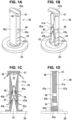
- FIG. 1 is schematic diagrams for explaining in detail the mixing nozzle according to the present invention, FIG. 1A being a perspective view, FIG. 1B being an exploded perspective view, FIG. 1C being an exploded front view, and FIG. 1D being a side view.
- the mixing nozzle 40 is immersed in the decontamination solution in the water storage pool.
- the mixing nozzle 40 may be provided at a bottom of the water storage pool.
- the mixing nozzle 40 is used to mix gas from outside and the solution from a bottom side of the water storage pool toward an upward direction.
- the mixing nozzle 40 has its interior space divided into a throat section 41 and a diffuser section 42.
- the mixing nozzle 40 further includes a gas nozzle section 43, a first liquid suction port 44, a liquid nozzle section 45, a second liquid suction port 46, a baffle plate 47, and a jetting port 48.
- the throat section 41 is a section with a small internal cross-sectional area for accelerating mixed flow which is provided by mixing the gas and the solution.
- the diffuser section 42 is a section whose internal cross-sectional area expands in a tapered shape toward a downstream side from the throat section 41, i.e., upward in the drawings.
- the throat section 41 and the diffuser section 42 may be constituted by combining two block plates 41a.
- the block plates 41a may be made of , for example, stainless steel or resin.
- the block plate 41a has a shape in which the lower (upstream) side of the throat section 41 is shorter and the upper (downstream) side is longer, and the part of the throat section 41 is the thickest part and the width becomes gradually thinner toward the downstream direction of the diffuser section 42.
- the block plates 41a may be fixed by bolts or the like by which the front and back thereof are sandwiched by holding brackets 42a, as shown in the drawing.
- the present invention is not limited to this, and the throat section 41 and the diffuser section 42 may be provided by machining or the like a metal block or a resin block.
- the gas nozzle section 43 is arranged at an upstream side of the throat section 41, is supplied with the gas from outside, and has a gas nozzle tip 43a whose internal cross-sectional area reduces in a tapered shape toward a downstream. As shown in the drawing, the gas nozzle tip 43a has a rectangular-shaped jetting port.
- the gas nozzle section 43 can be made of a nozzle block 43b of, for example, stainless steel, resin or the like.
- the gas nozzle section 43 has a flange 43c appropriately and may be fixed to a base 20. The base 20 may be fixed to appropriately the bottom of the water pool.
- the gas nozzle section 43 may be configured such that the internal cross-sectional area in the direction of its thickness has a flared shape toward the upstream as shown in FIG. 1D . That is, the upstream side is expanded in a flared shape with respect to the thickness direction. This makes it possible to expand a cross-sectional area of a flow path of an inlet side of the gas nozzle.
- the gas nozzle section 43 is shown in the illustrated example as an integral part of the mixing nozzle 40.
- the present invention is not limited to this and the gas nozzle section can be configured as a nozzle that is separate from the mixing nozzle 40 and separately fixed to the base 20.
- the first liquid suction port 44 liquidly absorbs the solution in the water storage pool from a side of the gas nozzle section 43 toward the gas nozzle tip 43a. That is, the first liquid suction port 44 is provided at an upstream side of a foot of the gas nozzle section 43. At the gas nozzle tip 43a, the solution is liquidly absorbed from the first liquid suction port 44 because the negative pressure generated by the high-speed jet of gas is produced. For example, it may be configured that the solution can flow from the gap for the liquid nozzle section 45 as described later toward a space of a side portion of the gas nozzle section 43.
- the side portion of the gas nozzle section 43 means the upstream side of the gas nozzle tip 43a of the gas nozzle section 43.
- the first liquid suction port 44 may be configured such that the solution is liquidly absorbed at an angle obliquely upward in accordance with the tip shape of the gas nozzle section 43.
- the liquid nozzle section 45 extends to the downstream side of the gas nozzle section 43 with intervening the first liquid suction port 44, and has a liquid nozzle tip 45a whose internal cross-sectional area reduces in a tapered shape toward the downstream. As shown in the drawing, the liquid nozzle tip 45a has a rectangular-shaped jet flow port.
- the liquid nozzle section 45 may be made of a tapered block 45b of, for example, stainless steel, resin or the like.
- the liquid nozzle section 45 has a shape that tapers toward downstream in which the edge of the downstream side of the first liquid suction port 44 is a foot. As shown in FIG.
- the liquid nozzle section 45 may be constituted such that, for example, two tapered blocks 45b are arranged opposite with each other and the internal cross-sectional area thereof reduces in a tapered shape.
- the tapered blocks 45b of the liquid nozzle section 45 may also be fixed by bolts or the like by which the front and back thereof are sandwiched by the holding brackets 42a.
- the second liquid suction port 46 is arranged at the upstream side of the throat section 41 and the downstream side of the liquid nozzle section 45, and liquidly absorbs the solution in the water storage pool from a side of the liquid nozzle section 45 toward the liquid nozzle tip 45a. That is, the second liquid suction port 46 is arranged at the upstream side of a foot of the liquid nozzle section 45.
- the first liquid suction port 44 and the second liquid suction port 46 may be arranged at the upstream side and the downstream side sandwiching the liquid nozzle section 45.
- the solution is further liquidly absorbed from the second liquid suction port 46 because the negative pressure generated by the high-speed jet of gas and solution is produced.
- the solution can flow from the gap for the block plate 41a toward a space of a side portion of the liquid nozzle section 45.
- the side portion of the liquid nozzle section 45 means the upstream side of the liquid nozzle tip 45a of the liquid nozzle section 45.
- the second liquid suction port 46 may be configured such that the solution is liquidly absorbed at an angle obliquely upward in accordance with the tip shape of the liquid nozzle section 45.
- the gas nozzle section 43 and the liquid nozzle section 45 are arranged so as to fit with each other via the first liquid suction port 44.
- the throat section 41 and the liquid nozzle section 45 are arranged so as to fit with each other via the second liquid suction port 46. That is, the flowing to the throat section 41 occurs by the two stages which jetting occurs while the gas from the gas nozzle section 43 and the solution from the first liquid suction port 44 are mixed, and then jetting further occurs from the liquid nozzle section 45 while the solution from the second liquid suction port 46 is added.
- the liquid nozzle tip 45a is preferably configured to be narrower than the throat section 41 as shown in FIG. 1C . This makes it possible to accelerate the solution liquidly absorbed from the first liquid suction port 44 at a higher speed.
- the gas nozzle tip 43a is preferably configured to be narrower than the liquid nozzle tip 45a as shown in FIG. 1C . This makes it possible to jet the supplied gas from outside at a higher speed. It may be configured that the outer edge of the gas nozzle tip 43a is chamfered or otherwise appropriately to reduce the outlet pressure loss.
- the solution liquidly absorbed from the second liquid suction port 46 passes through between the tapered block 45b of the liquid nozzle section 45 and the block plate 41a.
- the throat effect may also be obtained at this position by partially narrowing the space between the tapered block 45b and the block plate 41a. This will also allow the solution liquidly absorbed from the second liquid suction port 46 to be accelerated at a higher speed.
- the baffle plate 47 is arranged at the downstream edge of the diffuser section 42.
- the gas discharged from the gas nozzle tip 43a is accelerated in the throat section 41 together with the solution liquidly absorbed from the first liquid suction port 44 and the second liquid suction port 46. That is, the solution flows into the diffuser section 42 while being accelerated through the two stages at the first liquid suction port 44 and the second liquid suction port 46.
- the solution then becomes a mixed flow of the gas and the liquid in the diffuser section 42.
- the baffle plate 47 may be arranged such that this mixed flow collides in front of the downstream edge of the diffuser section 42.
- the mixed flow collided on the baffle plate 47 is divided to the left and right and reversed.
- Jetting port 48 is in which the mixed flow divided and reversed by the baffle plate 47 jets out in a direction not directly toward an upper direction of the water storage pool. That is, the mixed flow is jetted out with changing of the direction toward obliquely downward. The mixed flow is jetted out while being subjected to centrifugal force.
- the jetting port 48 may be provided, for example, by the gap between the tip of the block plate 41a constituting the throat section 41 and the diffuser section 42 and the baffle plate 47.
- the baffle plate 47 preferably has an impact surface for the mixed flow being an arc-shape so as to jet out the mixed flow divided and reversed by the diffuser section 42 obliquely toward the bottom of the water storage pool as shown in FIG. 1C . This results in that the mixed flow efficiently jets obliquely toward the bottom of the water storage pool.
- FIG. 2 is a schematic side view for explaining in detail the baffle plate of the mixing nozzle of the gas purification device according to the present invention.
- the same reference numerals as those in FIG. 1 denote the same parts.
- the baffle plate 47 has a convex jet guide 47a.
- the convex jet guide 47a may be arranged such that the convex part faces upstream on the impact surface of the mixed flow so as to guide the mixed flow to the jetting port 48. This results in that the mixed flow can efficiently be divided to the left and right and that the high-speed reversed flow of the mixed flow can more efficiently be formed.
- a jetting port guide 48a may be provided to strengthen the jetting port 48.
- the jetting port guide 48a allows the mixed flow jetted from the jetting port 48 to more efficiently jet out obliquely toward the bottom of the water storage pool.
- the mixing nozzle according to the present invention as structured above can efficiently mix the gas and the solution.
- the mixing nozzle according to the present invention can also be applied to a so-called bioreactor, for example.
- the bioreactor is a device that performs biochemical reactions using a biocatalyst. That is, a culture solution is used instead of a decontamination solution, and gas containing in high concentration carbon dioxide or methane, which is global warming gas, is used instead of contaminated gas.
- gas containing in high concentration carbon dioxide or methane which is global warming gas
- these gases or the oxygen needed by the cells can be agitated into microbubbles, which can be supplied efficiently. Since this enables the reduction of carbon dioxide to oxygen and organic matter through photosynthesis by microorganisms and algae, or the conversion of methane to methanol by microorganisms, it is possible to reduce global warming gas in the atmosphere on an industrial scale.
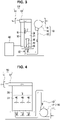
- FIG. 3 is a schematic configuration diagram for explaining a contaminated gas purification device according to the present invention.
- the contaminated gas purification device according to the present invention mainly is constituted by an intake section 10, a water storage pool 30, a mixing nozzle 40, and an exhaust section 50.
- the mixing nozzle 40 described above what is described as the gas from outside is in this example the contaminated gas containing microparticles, which are contaminants.
- the solution stored in the water storage pool is in this example decontamination solution for decontaminating the microparticles, which are contaminants contained in the contaminated gas.
- the intake section 10 is constituted by a blower section 12 and a blower tube 13, that intakes from an air intake port 11.
- the blower section 12 intakes the contaminated gas containing microparticles, which are contaminants, from the air intake port 11.
- the blower tube 13 blows the intake contaminated gas toward the water storage pool 30 side, which will be described later.
- the blower section 12 may use, for example, such a blower as a sirocco fan using an impeller.
- the blower tube 13 may be formed, for example, in a U-shape as shown in the drawing.
- blower section 12 of the intake section 10 when the blower section 12 of the intake section 10 is disposed at a higher position than the decontamination solution 31 in the water storage pool 30 as described later, it is possible to prevent the blower section 12 from becoming submerged even if the decontamination solution 31 in the water storage pool 30 flows back.
- the blower tube 13 of the intake section 10 is then connected to the gas nozzle section 43 of the mixing nozzle 40.
- the blower tube 13 has a flange appropriately and may be fixed to the base 20.
- the water storage pool 30 stores the decontamination solution 31.
- the decontamination solution 31 is for being mixed with the contaminated gas and decontaminating microparticles contained in the contaminated gas.
- the decontamination solution 31 is so-called scrubber water.
- the decontamination solution 31 may be capable of decontaminating at least one of radioactive substances, viruses, bacteria, molds, pollen, photochemical oxidants, and volcanic gases, for example.
- the decontamination solution 31 may be, for example, hypochlorite water or chlorine dioxide water, which is effective in decontaminating microparticles such as viruses. It may also be alkaline water such as sodium hydroxide solution, which is effective in removing radioactive substances or decomposing volatile organic compounds.
- the baffle plate 47 of the mixing nozzle 40 described above which is shown in detail in FIG. 1 , etc., divides and reverses solid-gas-liquid three-phase flow such that high-speed reversed flow of the solid-gas-liquid three-phase flow of the contaminated gas and the decontamination solution mixed in the diffuser section 42 is formed and that the microparticles and the decontamination solution are mixed by separating the microparticles and the gas in the contaminated gas by centrifugal force.
- the decontamination effect of the decontamination solution cannot be obtained since the microparticles contained in the bubbles is not directly contacted with the decontamination solution, however, in the mixing nozzle 40 of the contaminated gas purification device according to the present invention, it is possible to certainly mix the microparticles and the decontamination solution by separating the microparticles and the gas in the contaminated gas by centrifugal force.
- the decontaminated gas discharged into the water storage pool 30 using the mixing nozzle 40 according to the present invention may be exhausted from the exhaust section 50.
- the decontaminated gas discharged into the water storage pool 30 becomes bubbles in the decontamination solution 31 of the water storage pool 30 and is released from the decontaminated solution 31.
- the released gas may be exhausted from the exhaust section 50.
- the exhaust section 50 may be constituted by, for example, an exhaust port 51 and a mist separating section 52.
- the mist separating section 52 separates mist generated in the water storage pool 30 into the decontamination solution 31 and the gas. This is because not only the gas after decontamination flies up on the decontamination solution 31, but also the decontamination solution 31 becomes mist and flies up.
- the mist may be exhausted from the exhaust port 51 as it is, or it may be separated into the decontamination solution 31 and the gas using the mist separating section 52, and only the gas after decontamination may be exhausted.
- the mist separating section 52 may also return the separated decontamination solution to the water storage pool 30.
- the decontamination solution separated by the mist separating section 52 is returned to the water storage pool 30 using the separated water collection pipe 53. This also allows the decontamination solution to be reused.
- the contaminated gas purification device may be configured to have a solution volume control section 60.
- the solution volume control section 60 controls solution volume of the decontamination solution 31 in the water storage pool 30.
- the solution volume control section 60 measures changes of the water level of the decontamination solution 31 using, for example, a float 61 which measures the water level of the decontamination solution 31 in the water storage pool 30, and when the water level drops below a predetermined level, the decontamination solution 31 may be replenished from a storage tank or the like.
- a drain valve 62 may be configured to be installed at the bottom of the water storage pool 30 to let the decontamination solution 31 out of the water storage pool 30.
- the exhaust section 50 may also have an atomizer to mix and atomize the decontamination solution 31 in the water storage pool 30 with the gas after decontamination.
- the atomizer may use, for example, an ultrasonic atomizer. By exhausting the decontamination solution atomized by the atomizer from the exhaust port 51, it is also possible to fill the space with the decontamination solution.
- the exhaust section 50 may have a plasma sterilizer.
- the contaminated gas purification device according to the present invention can exhaust the decontaminated gas by providing with various functions to the exhaust section 50.
- a pressure sensor or the like may be provided as appropriate to monitor the exhaust.
- FIG. 4 is a schematic diagram for explaining another layout of the intake section of the contaminated gas purification device according to the present invention.
- the same reference numerals as those in FIGS. 1 and 3 denote the same parts.
- an example in which a plurality of mixing nozzles 40 of the present invention are arranged is shown. This can increase the purification efficiency of the contaminated gas.
- the blower section 12 of the intake section 10 is disposed at a lower position than the decontamination solution 31 of the water storage pool 30. This is because the blower section 12 is generally heavy and may be more stable when placed at the bottom.
- the blower tube 13 may be formed in, for example, an inverted U-shape as shown in the drawing.
- the inverted U-shaped folded portion may be configured to be disposed at a higher position than the decontamination solution 31 in the water storage pool 30. It is possible to prevent the blower section 12 from becoming submerged even if the decontamination solution 31 in the water storage pool 30 flows back.
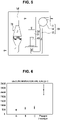
- FIG. 5 is a schematic diagram for explaining an application example of the contaminated gas purification device according to the present invention.
- the another decontaminator 70 may be, for example, a metal fiber filter, a glass fiber filter, an iodine adsorption filter, a volatile organic compound decomposition catalyst filter, etc.
- the metal fiber filter is resistant to high temperature and does not pose a fire hazard. It also has the advantage of being less prone to clogging. A combination of several such dry filters may be used.
- the another decontaminator 70 may appropriately be selected depending on the contaminant to be decontaminated. That is, it may be appropriately selected according to a kind of the decontamination solution 31 in the water storage pool 30.
- the contaminant to be decontaminated is, for example, a radioactive material
- alkaline water such as sodium hydroxide solution is selected as the decontamination solution 31 in the water storage pool 30.
- the radioactive material is first decontaminated.
- a two-stage filter is used as the another decontaminator 70. That is, the decontaminator 70 may use one having a first filter section using metal fibers and a second filter section using iodine adsorbent material.
- the iodine adsorbent is, for example, silver zeolite (AgX).
- the first filter section removes water droplets or particulates from the decontamination solution 31.
- the second filter section performs adsorption and removal of radioactive iodine.
- Such contaminated gas purification device according to the present invention can be used to directly be connected to an exhaust port of a containment vessel when venting a nuclear power generator, for example.
- the contaminant to be decontaminated is, for example, a virus, hypochlorite or chlorine dioxide water is selected as the decontamination solution 31 in the water storage pool 30.
- the virus is first sterilized.
- a two-stage filter is used as the another decontaminator 70. That is, the decontaminator 70 may use one having a first filter section using metal fibers and a second filter section using glass fibers.
- the glass fiber of the second filter section is, for example, a HEPA filter (High Efficiency Particulate Air Filter).
- the first filter section removes water droplets and microparticles from the decontamination solution 31.
- the second filter section removes microparticles.
- the contaminated gas purification device according to the present invention can be used to directly be connected to an air conditioning system in a hospital, for example.
- the decontaminator 70 may use one having a first filter section using metal fibers and a second filter section using a volatile organic compound decomposition catalyst (VOC catalyst).
- VOC catalyst volatile organic compound decomposition catalyst
- the first filter section removes water droplets and microparticles from the decontamination solution 31.
- the second filter section decomposes and removes volatile organic compound by catalytic reaction.
- the contaminant to be decontaminated is, for example, volcanic gas
- alkaline water such as sodium hydroxide solution
- the decontamination solution 31 in the water storage pool 30 is selected as the decontamination solution 31 in the water storage pool 30.
- neutralization removal of hydrogen sulfide and other contaminants is first performed.
- a two-stage filter is used as the another decontaminator 70. That is, the decontaminator 70 may use one having a first filter section using metal fibers and a second filter section using glass fibers.
- the glass fiber is, for example, a HEPA filter.
- the first filter section removes water droplets from the decontamination solution 31 and microparticles such as volcanic ash.
- the second filter section further removes microparticles such as volcanic ash.
- the contaminated gas purification device ensures that microparticles, which are contaminants contained in contaminated gas, are certainly mixed with the decontamination solution and purified, and furthermore, by combining conventional decontaminator, contaminants that could not be removed by the decontamination solution can be more certainly removed.
- a decontamination factor (DF) of the contaminated gas purification device according to the present invention and that using a mixing nozzle of another structure are compared.
- FIG. 6 is a comparison graph of decontamination factors between the contaminated gas purification device according to the present invention and comparative examples.
- the mixing nozzles used as comparative examples are the following.
- a simulated substance of a radioactive material are used as a contaminant.
- barium sulfate is used as the simulated substance.
- the DF is dramatically larger when the two-stage configuration of the first suction port and the second suction port is used as in the present invention.
- the mixing nozzle of the contaminated gas purification device according to the present invention is a very effective structure for the decontamination function in the contaminated gas purification device. It is also possible to use the mixing nozzle described in the present invention in the mixing section of a general wet-type contaminated gas purification device.
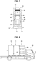
- FIG. 7 is a schematic configuration diagram for explaining another application example of the contaminated gas purification device according to the present invention.
- this example is an integrated contaminated gas purification device.
- the basic configuration is the same as the example shown in FIG. 5 .
- the integrated contaminated gas purification device of FIG. 7 has, for example, a water level lower limit sensor 80. When the water level drops below a predetermined level, a warning or the like should be issued, and the decontamination solution 31 may be added as needed.
- a wave absorber 81 may also be provided.
- the wave absorber 81 is, for example, a cage-shaped perforated metal plate.
- the wave absorber 81 may be configured to be positioned above the water surface using a float 82. Furthermore, an ultrasonic transducer 83 may be used to spray the decontamination solution 31. The ultrasonic transducer 83 can generate a fine mist or plasmarize with strong ultrasonic waves. The ultrasonic transducer 83 is best placed at a depth of a few centimeters below the water surface. Thus, as shown in the drawing, the ultrasonic transducer 83 may be arranged, for example, above the float 82 and below the wave absorber 81. This allows the ultrasonic transducer 83 to always vibrate at a depth of several centimeters below the water surface.
- the another decontaminator 70 may be provided, and finally the decontaminated gas may be exhausted from the exhaust port 51 of the exhaust section 50.
- Such an integrated contaminated gas purification device can be installed in, for example, a hospital examination room, a waiting room, a restaurant, various windows, etc., in the same way as a general air purifier.
- the contaminated gas purification device according to the present invention may also be configured to be connected to a face mask.
- the face mask is a sealed object, such as a protective mask, to which a tube or the like is connected, and is connected to the exhaust port 51 of the contaminated gas purification device. This allows the gas after decontamination to be supplied directly into the face mask.
- the contaminated gas purification device according to the present invention may be configured to be mountable on a transportation.
- a transportation such as a truck, etc.
- FIG. 8 is a schematic configuration diagram for explaining an example in which the contaminated gas purification device according to the present invention is configured to be movable.
- the same reference numerals as those in FIG. 3 denote the same parts.
- the contaminated gas purification device according to the present invention can be modularized and loaded on a truck 85.
- the module 86 is a modularized version of the basic form of the contaminated gas purification device according to the present invention as shown, for example, in FIG.
- each module can be sized to be transportable by trailer, helicopter, airplane or the like.
- the contaminated gas purification device according to the present invention is not limited to the above-described illustrated examples and may be variously modified without departing from the spirit and scope of the invention.
Landscapes
- Chemical & Material Sciences (AREA)
- Chemical Kinetics & Catalysis (AREA)
- Engineering & Computer Science (AREA)
- Health & Medical Sciences (AREA)
- Life Sciences & Earth Sciences (AREA)
- Analytical Chemistry (AREA)
- General Chemical & Material Sciences (AREA)
- Oil, Petroleum & Natural Gas (AREA)
- Animal Behavior & Ethology (AREA)
- Epidemiology (AREA)
- General Health & Medical Sciences (AREA)
- Public Health (AREA)
- Veterinary Medicine (AREA)
- Environmental & Geological Engineering (AREA)
- Geology (AREA)
- General Engineering & Computer Science (AREA)
- High Energy & Nuclear Physics (AREA)
- Physics & Mathematics (AREA)
- Biomedical Technology (AREA)
- Disinfection, Sterilisation Or Deodorisation Of Air (AREA)
- Gas Separation By Absorption (AREA)
Abstract
Description
- The present invention relates to a mixing nozzle and a contaminated gas purification device using the mixing nozzle, and more particularly to a mixing nozzle capable of mixing gas and solution. It also relates to a contaminated gas purification device that uses the mixing nozzle for purifying contaminated gas containing microparticles, which are contaminants, by mixing it with decontamination solution.
- Air purification devices are known to purify bacteria, viruses, radioactive materials, etc. in the air and discharge purified air. For example, the device of Patent Document 1 removes bacteria, viruses, etc. from the air by contacting indoor air with hypochlorous acid water. In this device, the hypochlorous acid water stored in a water reservoir is converted into water droplets, which are mixed with the air drawn in from an air intake port and jetted out from an exhaust port.
- Patent Document 1:
Japanese Patent Application Kokai Publication No. 2018-175740 - However, in the conventional air purification device as described in Patent Document 1, not all of the air drawn from the air intake port may contact with the hypochlorite water. Furthermore, even if the air completely contacts with the hypochlorite water, when microparticles, which are contaminants contained in the air, exist in the bubbles, the hypochlorite water does not contact with the microparticles surrounded by the bubbles, so that there is a risk that the air is jetted out from the exhaust port without being completely purified.
- In view of the above circumstances, the present invention is to provide a contaminated gas purification device capable of certainly purifying contaminated gas by mixing microparticles, which are contaminants contained in the contaminated gas with decontamination solution. The present invention also is to provide a mixing nozzle capable of efficiently mixing gas and solution.
- To attain the above object of the present invention, a mixing nozzle according to the present invention may include: a throat section which is a small internal cross-sectional area for accelerating mixed flow which is provided by mixing the gas and the solution; a diffuser section whose internal cross-sectional area expands in a tapered shape toward a downstream side from the throat section; a gas nozzle section having a gas nozzle tip whose internal cross-sectional area reduces in a tapered shape toward a downstream, arranged at an upstream side of the throat section, and supplied with the gas from outside; a first liquid suction port for liquidly absorbing the solution in the water storage pool from a side of the gas nozzle section toward the gas nozzle tip; a liquid nozzle section extending to the downstream side of the gas nozzle section with intervening the first liquid suction port, and having a liquid nozzle tip whose internal cross-sectional area reduces in a tapered shape toward the downstream; a second liquid suction port for liquidly absorbing the solution in the water storage pool from a side of the liquid nozzle section toward the liquid nozzle tip, arranged at the upstream side of the throat section and the downstream side of the liquid nozzle section; a baffle plate provided such that the gas discharged from the gas nozzle tip is accelerated in the throat section together with the solution liquidly absorbed from the first liquid suction port and the second liquid suction port and that the mixed flow mixed in the diffuser section collides in front of a downstream end of the diffuser section, in which the baffle plate divides and reverses the mixed flow such that high-speed reversed flow of the mixed flow is formed and the gas and the solution are mixed by centrifugal force; and a jetting port in which the mixed flow divided and reversed by the baffle plate jets out in a direction not directly toward an upper direction of the water storage pool.
- The baffle plate may have an impact surface for the mixed flow being an arc-shape so as to jet out the mixed flow divided and reversed by the diffuser section obliquely toward a bottom of the water storage pool.
- The baffle plate may have a convex jet guide facing the upstream side on an impact surface for the mixed flow so as to guide the mixed flow to the jetting port.
- The liquid nozzle tip of the liquid nozzle section may be narrower than the throat section.
- The gas nozzle tip of the gas nozzle portion may be narrower than the liquid nozzle tip.
- The gas nozzle section may be configured such that the internal cross-sectional area in the direction of its thickness has a flared shape toward the upstream.
- A contaminated gas purification device that uses the mixing nozzle according to the present invention, for purifying contaminated gas that is gas from outside containing microparticles, which are contaminants, may include: an intake section having a blower section that intakes contaminated gas containing microparticles, which are contaminants, through an air intake port, and having a blower tube that blows the intake contaminated gas; a water storage pool for storing decontamination solution for decontaminating microparticles, which are contaminants contained in the contaminated gas; and an exhaust section for exhausting the decontaminated gas from the water storage pool, the blower tube of the intake section being connected to the gas nozzle section of the mixing nozzle, the baffle plate dividing and reverting solid-gas-liquid three-phase flow such that high-speed reversed flow of the solid-gas-liquid three-phase flow of the contaminated gas and the decontamination solution mixed in the diffuser section is formed and that the microparticles and the decontamination solution are mixed by separating the microparticles and the gas in the contaminated gas by centrifugal force.
- The blower section of the intake section may be disposed at a higher position than the decontamination solution in the water storage pool, and the blower tube may be formed in a U-shape whose folded back portion of the U-shape is disposed at a lower position than the decontamination solution in the water storage pool.
- The blower section of the intake section may be disposed at a lower position than the decontamination solution in the water storage pool, and the blower tube may be formed in an inverted U-shape whose folded back portion of the inverted U-shape is disposed at a higher position than the decontamination solution in the water storage pool.
- Further, it may include a solution volume control section that controls solution volume of the decontamination solution in the water storage pool.
- The exhaust section may have a mist separating section that separates mist generated in the water storage pool into the decontamination solution and the gas, the mist separating section returning the decontamination solution separated to the water storage pool.
- The exhaust section may further have an atomizer or a plasma sterilizer for mixing and atomizing the decontamination solution in the water storage pool with gas after decontamination.
- The exhaust section may further be connected to another decontaminator.
- The another decontaminator may be at least one of a metal fiber filter, a glass fiber filter, an iodine adsorption filter, and a volatile organic compound decomposition catalyst filter.
- The decontamination solution in the water storage pool may be constituted by alkaline water, and the another decontaminator may be constituted by a first filter section using metal fibers and a second filter section using iodine adsorbent.
- The decontamination solution in the water storage pool may be constituted by hypochlorite water or chlorine dioxide water, and the another decontaminator may be constituted by a first filter section using metal fibers and a second filter section using glass fibers.
- The decontamination solution in the water storage pool may be constituted by alkaline water, and the another decontaminator may be constituted by a first filter section using metal fibers and a second filter section using a volatile organic compound decomposition catalyst.
- The decontamination solution in the water storage pool may be constituted by alkaline water, and the another decontaminator may be constituted by a first filter section using metal fibers and a second filter section using glass fibers.
- The decontamination solution in the water storage pool may be capable of decontaminating at least one of radioactive substances, viruses, bacteria, molds, pollen, photochemical oxidants, and volcanic gases.
- The contaminated gas purification device may further be configured to be mountable on a transportation.
- The contaminated gas purification device may further be configured to be connectable to a face mask.
- The contaminated gas purification device according to the present invention has an advantage of being capable of certainly mixing microparticles, which are contaminants contained in contaminated gas with the decontamination solution and purifying. Also, the mixing nozzle according to the present invention has an advantage of being capable of efficiently mixing the gas and the solution.
-
- [
FIG. 1] FIG. 1 is schematic diagrams for explaining in detail a mixing nozzle according to the present invention. - [
FIG. 2] FIG. 2 is a schematic side view for explaining in detail a baffle plate of the mixing nozzle according to the present invention. - [
FIG. 3] FIG. 3 is a schematic configuration diagram for explaining a contaminated gas purification device according to the present invention. - [
FIG. 4] FIG. 4 is a schematic diagram for explaining another layout of the intake section of the contaminated gas purification device according to the present invention. - [
FIG. 5] FIG. 5 is a schematic diagram for explaining an application example of the contaminated gas purification device according to the present invention. - [
FIG. 6] FIG. 6 is a comparison graph of decontamination factors between the contaminated gas purification device according to the present invention and comparative examples. - [
FIG. 7] FIG. 7 is a schematic configuration diagram for explaining another application example of the contaminated gas purification device according to the present invention. - [
FIG. 8] FIG. 8 is a schematic configuration diagram for explaining an example in which the contaminated gas purification device according to the present invention is configured to be movable. - Hereinafter, an embodiment for practicing the present invention will be described with reference to the illustrated examples. A mixing nozzle according to the present invention is immersed in solution stored in a water storage pool, and mixes gas from outside and the solution in the water storage pool from a bottom side of the water storage pool toward an upward direction. Here, when the mixing nozzle according to the present invention is applied to a contaminated gas purification device, the gas from outside is, for example, contaminated gas that contains microparticles, which are contaminants. The solution stored in the water storage pool is, for example, a decontamination solution for decontaminating the microparticles, which are contaminants, contained in the contaminated gas. The mixing nozzle according to the present invention can also be applied to a so-called bioreactor. The bioreactor is a device that performs biochemical reactions using a biocatalyst. In this case, the gas from outside can be such as any atmosphere containing carbon dioxide or methane which are global warming gases, or be oxygen and so on. The solution to be stored in the water storage pool in this case can be any culture solution.
- A detail of the mixing nozzle is described below using
FIG. 1. FIG. 1 is schematic diagrams for explaining in detail the mixing nozzle according to the present invention,FIG. 1A being a perspective view,FIG. 1B being an exploded perspective view,FIG. 1C being an exploded front view, andFIG. 1D being a side view. In the drawings, the same reference numerals as those inFIG. 1 denote the same parts. Themixing nozzle 40 is immersed in the decontamination solution in the water storage pool. The mixingnozzle 40 may be provided at a bottom of the water storage pool. The mixingnozzle 40 is used to mix gas from outside and the solution from a bottom side of the water storage pool toward an upward direction. As shown in the drawings, the mixingnozzle 40 has its interior space divided into athroat section 41 and adiffuser section 42. The mixingnozzle 40 further includes agas nozzle section 43, a firstliquid suction port 44, aliquid nozzle section 45, a secondliquid suction port 46, abaffle plate 47, and a jettingport 48. - The
throat section 41 is a section with a small internal cross-sectional area for accelerating mixed flow which is provided by mixing the gas and the solution. Thediffuser section 42 is a section whose internal cross-sectional area expands in a tapered shape toward a downstream side from thethroat section 41, i.e., upward in the drawings. Thethroat section 41 and thediffuser section 42 may be constituted by combining twoblock plates 41a. Theblock plates 41a may be made of , for example, stainless steel or resin. In the front view ofFIG. 1C , theblock plate 41a has a shape in which the lower (upstream) side of thethroat section 41 is shorter and the upper (downstream) side is longer, and the part of thethroat section 41 is the thickest part and the width becomes gradually thinner toward the downstream direction of thediffuser section 42. By arranging twoblock plates 41a of such shape opposite each other, thethroat section 41 anddiffuser section 42 are provided in the internal space thereof. Theblock plates 41a may be fixed by bolts or the like by which the front and back thereof are sandwiched by holdingbrackets 42a, as shown in the drawing. However, the present invention is not limited to this, and thethroat section 41 and thediffuser section 42 may be provided by machining or the like a metal block or a resin block. - The
gas nozzle section 43 is arranged at an upstream side of thethroat section 41, is supplied with the gas from outside, and has agas nozzle tip 43a whose internal cross-sectional area reduces in a tapered shape toward a downstream. As shown in the drawing, thegas nozzle tip 43a has a rectangular-shaped jetting port. Thegas nozzle section 43 can be made of anozzle block 43b of, for example, stainless steel, resin or the like. Thegas nozzle section 43 has aflange 43c appropriately and may be fixed to abase 20. The base 20 may be fixed to appropriately the bottom of the water pool. - The
gas nozzle section 43 may be configured such that the internal cross-sectional area in the direction of its thickness has a flared shape toward the upstream as shown inFIG. 1D . That is, the upstream side is expanded in a flared shape with respect to the thickness direction. This makes it possible to expand a cross-sectional area of a flow path of an inlet side of the gas nozzle. - The
gas nozzle section 43 is shown in the illustrated example as an integral part of the mixingnozzle 40. However, the present invention is not limited to this and the gas nozzle section can be configured as a nozzle that is separate from the mixingnozzle 40 and separately fixed to thebase 20. - The first
liquid suction port 44 liquidly absorbs the solution in the water storage pool from a side of thegas nozzle section 43 toward thegas nozzle tip 43a. That is, the firstliquid suction port 44 is provided at an upstream side of a foot of thegas nozzle section 43. At thegas nozzle tip 43a, the solution is liquidly absorbed from the firstliquid suction port 44 because the negative pressure generated by the high-speed jet of gas is produced. For example, it may be configured that the solution can flow from the gap for theliquid nozzle section 45 as described later toward a space of a side portion of thegas nozzle section 43. Here, the side portion of thegas nozzle section 43 means the upstream side of thegas nozzle tip 43a of thegas nozzle section 43. As shown in the drawing, the firstliquid suction port 44 may be configured such that the solution is liquidly absorbed at an angle obliquely upward in accordance with the tip shape of thegas nozzle section 43. - The
liquid nozzle section 45 extends to the downstream side of thegas nozzle section 43 with intervening the firstliquid suction port 44, and has aliquid nozzle tip 45a whose internal cross-sectional area reduces in a tapered shape toward the downstream. As shown in the drawing, theliquid nozzle tip 45a has a rectangular-shaped jet flow port. Theliquid nozzle section 45 may be made of atapered block 45b of, for example, stainless steel, resin or the like. Theliquid nozzle section 45 has a shape that tapers toward downstream in which the edge of the downstream side of the firstliquid suction port 44 is a foot. As shown inFIG. 1C , theliquid nozzle section 45 may be constituted such that, for example, two taperedblocks 45b are arranged opposite with each other and the internal cross-sectional area thereof reduces in a tapered shape. The taperedblocks 45b of theliquid nozzle section 45 may also be fixed by bolts or the like by which the front and back thereof are sandwiched by the holdingbrackets 42a. - The second
liquid suction port 46 is arranged at the upstream side of thethroat section 41 and the downstream side of theliquid nozzle section 45, and liquidly absorbs the solution in the water storage pool from a side of theliquid nozzle section 45 toward theliquid nozzle tip 45a. That is, the secondliquid suction port 46 is arranged at the upstream side of a foot of theliquid nozzle section 45. The firstliquid suction port 44 and the secondliquid suction port 46 may be arranged at the upstream side and the downstream side sandwiching theliquid nozzle section 45. At theliquid nozzle tip 45a, the solution is further liquidly absorbed from the secondliquid suction port 46 because the negative pressure generated by the high-speed jet of gas and solution is produced. For example, it may be configured that the solution can flow from the gap for theblock plate 41a toward a space of a side portion of theliquid nozzle section 45. Here, the side portion of theliquid nozzle section 45 means the upstream side of theliquid nozzle tip 45a of theliquid nozzle section 45. As shown in the drawing, the secondliquid suction port 46 may be configured such that the solution is liquidly absorbed at an angle obliquely upward in accordance with the tip shape of theliquid nozzle section 45. - As explained, in the mixing nozzle according to the present invention, the
gas nozzle section 43 and theliquid nozzle section 45 are arranged so as to fit with each other via the firstliquid suction port 44. Also, thethroat section 41 and theliquid nozzle section 45 are arranged so as to fit with each other via the secondliquid suction port 46. That is, the flowing to thethroat section 41 occurs by the two stages which jetting occurs while the gas from thegas nozzle section 43 and the solution from the firstliquid suction port 44 are mixed, and then jetting further occurs from theliquid nozzle section 45 while the solution from the secondliquid suction port 46 is added. - Here, specifically, in the
liquid nozzle section 45, theliquid nozzle tip 45a is preferably configured to be narrower than thethroat section 41 as shown inFIG. 1C . This makes it possible to accelerate the solution liquidly absorbed from the firstliquid suction port 44 at a higher speed. - Also, specifically, in the
gas nozzle section 43, thegas nozzle tip 43a is preferably configured to be narrower than theliquid nozzle tip 45a as shown inFIG. 1C . This makes it possible to jet the supplied gas from outside at a higher speed. It may be configured that the outer edge of thegas nozzle tip 43a is chamfered or otherwise appropriately to reduce the outlet pressure loss. - Also, the solution liquidly absorbed from the second
liquid suction port 46 passes through between thetapered block 45b of theliquid nozzle section 45 and theblock plate 41a. In this case, as shown inFIG. 1C , the throat effect may also be obtained at this position by partially narrowing the space between thetapered block 45b and theblock plate 41a. This will also allow the solution liquidly absorbed from the secondliquid suction port 46 to be accelerated at a higher speed. - The
baffle plate 47 is arranged at the downstream edge of thediffuser section 42. First, the gas discharged from thegas nozzle tip 43a is accelerated in thethroat section 41 together with the solution liquidly absorbed from the firstliquid suction port 44 and the secondliquid suction port 46. That is, the solution flows into thediffuser section 42 while being accelerated through the two stages at the firstliquid suction port 44 and the secondliquid suction port 46. The solution then becomes a mixed flow of the gas and the liquid in thediffuser section 42. Thebaffle plate 47 may be arranged such that this mixed flow collides in front of the downstream edge of thediffuser section 42. The mixed flow collided on thebaffle plate 47 is divided to the left and right and reversed. This results in the formation of a high-speed reversed flow of the mixed flow, and the gas and the solution are mixed by centrifugal force. That is, it is possible to certainly mix the gas and the solution by the centrifugal force through the high-speed reversed flow. - Jetting
port 48 is in which the mixed flow divided and reversed by thebaffle plate 47 jets out in a direction not directly toward an upper direction of the water storage pool. That is, the mixed flow is jetted out with changing of the direction toward obliquely downward. The mixed flow is jetted out while being subjected to centrifugal force. The jettingport 48 may be provided, for example, by the gap between the tip of theblock plate 41a constituting thethroat section 41 and thediffuser section 42 and thebaffle plate 47. - Here, specifically, the
baffle plate 47 preferably has an impact surface for the mixed flow being an arc-shape so as to jet out the mixed flow divided and reversed by thediffuser section 42 obliquely toward the bottom of the water storage pool as shown inFIG. 1C . This results in that the mixed flow efficiently jets obliquely toward the bottom of the water storage pool. - In addition, a
convex jet guide 47a may be provided, as shown inFIG. 2. FIG. 2 is a schematic side view for explaining in detail the baffle plate of the mixing nozzle of the gas purification device according to the present invention. In the drawing, the same reference numerals as those inFIG. 1 denote the same parts. As shown in the drawing, thebaffle plate 47 has aconvex jet guide 47a. Theconvex jet guide 47a may be arranged such that the convex part faces upstream on the impact surface of the mixed flow so as to guide the mixed flow to the jettingport 48. This results in that the mixed flow can efficiently be divided to the left and right and that the high-speed reversed flow of the mixed flow can more efficiently be formed. - Also, as shown in the drawing, a jetting
port guide 48a may be provided to strengthen the jettingport 48. The jettingport guide 48a allows the mixed flow jetted from the jettingport 48 to more efficiently jet out obliquely toward the bottom of the water storage pool. - The mixing nozzle according to the present invention as structured above can efficiently mix the gas and the solution.
- Also, the mixing nozzle according to the present invention can also be applied to a so-called bioreactor, for example. The bioreactor is a device that performs biochemical reactions using a biocatalyst. That is, a culture solution is used instead of a decontamination solution, and gas containing in high concentration carbon dioxide or methane, which is global warming gas, is used instead of contaminated gas. By ventilating these gases into the culture solution with the mixing nozzle according to the present invention, these gases or the oxygen needed by the cells can be agitated into microbubbles, which can be supplied efficiently. Since this enables the reduction of carbon dioxide to oxygen and organic matter through photosynthesis by microorganisms and algae, or the conversion of methane to methanol by microorganisms, it is possible to reduce global warming gas in the atmosphere on an industrial scale.
- Next, a contaminated gas purification device that uses the mixing nozzle according to the present invention described above for purifying contaminated gas that is gas from outside containing microparticles, which are contaminants, will be described.
FIG. 3 is a schematic configuration diagram for explaining a contaminated gas purification device according to the present invention. In the drawing, the same reference numerals as those inFIG. 1 denote the same parts. As shown in the drawing, the contaminated gas purification device according to the present invention mainly is constituted by anintake section 10, awater storage pool 30, a mixingnozzle 40, and anexhaust section 50. In the mixingnozzle 40 described above, what is described as the gas from outside is in this example the contaminated gas containing microparticles, which are contaminants. Also, what is described as the solution stored in the water storage pool is in this example decontamination solution for decontaminating the microparticles, which are contaminants contained in the contaminated gas. - The
intake section 10 is constituted by ablower section 12 and ablower tube 13, that intakes from anair intake port 11. Theblower section 12 intakes the contaminated gas containing microparticles, which are contaminants, from theair intake port 11. Theblower tube 13 blows the intake contaminated gas toward thewater storage pool 30 side, which will be described later. Theblower section 12 may use, for example, such a blower as a sirocco fan using an impeller. Theblower tube 13 may be formed, for example, in a U-shape as shown in the drawing. As shown in the illustrated example, when theblower section 12 of theintake section 10 is disposed at a higher position than thedecontamination solution 31 in thewater storage pool 30 as described later, it is possible to prevent theblower section 12 from becoming submerged even if thedecontamination solution 31 in thewater storage pool 30 flows back. - The
blower tube 13 of theintake section 10 is then connected to thegas nozzle section 43 of the mixingnozzle 40. For example, theblower tube 13 has a flange appropriately and may be fixed to thebase 20. - The
water storage pool 30 stores thedecontamination solution 31. Thedecontamination solution 31 is for being mixed with the contaminated gas and decontaminating microparticles contained in the contaminated gas. Thedecontamination solution 31 is so-called scrubber water. Thedecontamination solution 31 may be capable of decontaminating at least one of radioactive substances, viruses, bacteria, molds, pollen, photochemical oxidants, and volcanic gases, for example. Specifically, thedecontamination solution 31 may be, for example, hypochlorite water or chlorine dioxide water, which is effective in decontaminating microparticles such as viruses. It may also be alkaline water such as sodium hydroxide solution, which is effective in removing radioactive substances or decomposing volatile organic compounds. - Here, the
baffle plate 47 of the mixingnozzle 40 described above, which is shown in detail inFIG. 1 , etc., divides and reverses solid-gas-liquid three-phase flow such that high-speed reversed flow of the solid-gas-liquid three-phase flow of the contaminated gas and the decontamination solution mixed in thediffuser section 42 is formed and that the microparticles and the decontamination solution are mixed by separating the microparticles and the gas in the contaminated gas by centrifugal force. That is, the decontamination effect of the decontamination solution cannot be obtained since the microparticles contained in the bubbles is not directly contacted with the decontamination solution, however, in the mixingnozzle 40 of the contaminated gas purification device according to the present invention, it is possible to certainly mix the microparticles and the decontamination solution by separating the microparticles and the gas in the contaminated gas by centrifugal force. - The decontaminated gas discharged into the
water storage pool 30 using the mixingnozzle 40 according to the present invention may be exhausted from theexhaust section 50. The decontaminated gas discharged into thewater storage pool 30 becomes bubbles in thedecontamination solution 31 of thewater storage pool 30 and is released from the decontaminatedsolution 31. The released gas may be exhausted from theexhaust section 50. - The
exhaust section 50 may be constituted by, for example, anexhaust port 51 and amist separating section 52. Themist separating section 52 separates mist generated in thewater storage pool 30 into thedecontamination solution 31 and the gas. This is because not only the gas after decontamination flies up on thedecontamination solution 31, but also thedecontamination solution 31 becomes mist and flies up. The mist may be exhausted from theexhaust port 51 as it is, or it may be separated into thedecontamination solution 31 and the gas using themist separating section 52, and only the gas after decontamination may be exhausted. - The
mist separating section 52 may also return the separated decontamination solution to thewater storage pool 30. For example, the decontamination solution separated by themist separating section 52 is returned to thewater storage pool 30 using the separatedwater collection pipe 53. This also allows the decontamination solution to be reused. - Furthermore, the contaminated gas purification device according to the present invention may be configured to have a solution
volume control section 60. The solutionvolume control section 60 controls solution volume of thedecontamination solution 31 in thewater storage pool 30. The solutionvolume control section 60 measures changes of the water level of thedecontamination solution 31 using, for example, afloat 61 which measures the water level of thedecontamination solution 31 in thewater storage pool 30, and when the water level drops below a predetermined level, thedecontamination solution 31 may be replenished from a storage tank or the like. Also, if necessary, adrain valve 62 may be configured to be installed at the bottom of thewater storage pool 30 to let thedecontamination solution 31 out of thewater storage pool 30. - The
exhaust section 50 may also have an atomizer to mix and atomize thedecontamination solution 31 in thewater storage pool 30 with the gas after decontamination. The atomizer may use, for example, an ultrasonic atomizer. By exhausting the decontamination solution atomized by the atomizer from theexhaust port 51, it is also possible to fill the space with the decontamination solution. - Furthermore, the
exhaust section 50 may have a plasma sterilizer. Thus, the contaminated gas purification device according to the present invention can exhaust the decontaminated gas by providing with various functions to theexhaust section 50. In addition, a pressure sensor or the like may be provided as appropriate to monitor the exhaust. - Another layout of the intake section of the contaminated gas purification device according to the present invention is explained using
FIG. 4. FIG. 4 is a schematic diagram for explaining another layout of the intake section of the contaminated gas purification device according to the present invention. In the drawing, the same reference numerals as those inFIGS. 1 and3 denote the same parts. In the illustrated example, an example in which a plurality of mixingnozzles 40 of the present invention are arranged is shown. This can increase the purification efficiency of the contaminated gas. As shown in the drawing, in this example, theblower section 12 of theintake section 10 is disposed at a lower position than thedecontamination solution 31 of thewater storage pool 30. This is because theblower section 12 is generally heavy and may be more stable when placed at the bottom. In this case, theblower tube 13 may be formed in, for example, an inverted U-shape as shown in the drawing. When theblower section 12 is disposed at a lower position than thedecontamination solution 31 in thewater storage pool 30 as shown in the drawing, the inverted U-shaped folded portion may be configured to be disposed at a higher position than thedecontamination solution 31 in thewater storage pool 30. It is possible to prevent theblower section 12 from becoming submerged even if thedecontamination solution 31 in thewater storage pool 30 flows back. - Next, an application example of the contaminated gas purification device according to the present invention is described.
FIG. 5 is a schematic diagram for explaining an application example of the contaminated gas purification device according to the present invention. In the drawing, the same reference numerals as those inFIG. 3 denote the same parts. As shown in the drawing, in the contaminated gas purification device according to the present invention, anotherdecontaminator 70 can be further connected to theexhaust section 50. The anotherdecontaminator 70 may be, for example, a metal fiber filter, a glass fiber filter, an iodine adsorption filter, a volatile organic compound decomposition catalyst filter, etc. The metal fiber filter is resistant to high temperature and does not pose a fire hazard. It also has the advantage of being less prone to clogging. A combination of several such dry filters may be used. The anotherdecontaminator 70 may appropriately be selected depending on the contaminant to be decontaminated. That is, it may be appropriately selected according to a kind of thedecontamination solution 31 in thewater storage pool 30. - Specifically, when the contaminant to be decontaminated is, for example, a radioactive material, alkaline water such as sodium hydroxide solution is selected as the
decontamination solution 31 in thewater storage pool 30. At this stage, the radioactive material is first decontaminated. Then, a two-stage filter is used as the anotherdecontaminator 70. That is, thedecontaminator 70 may use one having a first filter section using metal fibers and a second filter section using iodine adsorbent material. The iodine adsorbent is, for example, silver zeolite (AgX). The first filter section removes water droplets or particulates from thedecontamination solution 31. The second filter section performs adsorption and removal of radioactive iodine. Thus, by performing decontamination in multiple stages, the contaminants that could not be removed in thewater storage pool 30 can be certainly removed. Such contaminated gas purification device according to the present invention can be used to directly be connected to an exhaust port of a containment vessel when venting a nuclear power generator, for example. - Also, when the contaminant to be decontaminated is, for example, a virus, hypochlorite or chlorine dioxide water is selected as the
decontamination solution 31 in thewater storage pool 30. At this stage, the virus is first sterilized. Then, a two-stage filter is used as the anotherdecontaminator 70. That is, thedecontaminator 70 may use one having a first filter section using metal fibers and a second filter section using glass fibers. The glass fiber of the second filter section is, for example, a HEPA filter (High Efficiency Particulate Air Filter). The first filter section removes water droplets and microparticles from thedecontamination solution 31. The second filter section removes microparticles. The contaminated gas purification device according to the present invention can be used to directly be connected to an air conditioning system in a hospital, for example. - Also, when the contaminant to be decontaminated is, for example, photochemical smog, alkaline water such as sodium hydroxide solution is selected as the
decontamination solution 31 in thewater storage pool 30. At this stage, neutralization and removal of sulfuric acid compounds (SOx) and nitrogen oxides (NOx) are first performed. Then, a two-stage filter is used as the anotherdecontaminator 70. That is, thedecontaminator 70 may use one having a first filter section using metal fibers and a second filter section using a volatile organic compound decomposition catalyst (VOC catalyst). The first filter section removes water droplets and microparticles from thedecontamination solution 31. The second filter section decomposes and removes volatile organic compound by catalytic reaction. - Further, when the contaminant to be decontaminated is, for example, volcanic gas, alkaline water such as sodium hydroxide solution is selected as the
decontamination solution 31 in thewater storage pool 30. At this stage, neutralization removal of hydrogen sulfide and other contaminants is first performed. Then, a two-stage filter is used as the anotherdecontaminator 70. That is, thedecontaminator 70 may use one having a first filter section using metal fibers and a second filter section using glass fibers. The glass fiber is, for example, a HEPA filter. The first filter section removes water droplets from thedecontamination solution 31 and microparticles such as volcanic ash. The second filter section further removes microparticles such as volcanic ash. - Thus, the contaminated gas purification device according to the present invention ensures that microparticles, which are contaminants contained in contaminated gas, are certainly mixed with the decontamination solution and purified, and furthermore, by combining conventional decontaminator, contaminants that could not be removed by the decontamination solution can be more certainly removed.
- Next, the effectiveness of the contaminated gas purification device according to the present invention is explained. A decontamination factor (DF) of the contaminated gas purification device according to the present invention and that using a mixing nozzle of another structure are compared. Here, the decontamination factor is defined as DF = (Input powder volume) / (Output powder volume). That is, the higher the decontamination effect, the higher the DF value.
-
FIG. 6 is a comparison graph of decontamination factors between the contaminated gas purification device according to the present invention and comparative examples. The mixing nozzles used as comparative examples are the following. - Comparative Example A: only a gas nozzle connected to the intake section without a mixing nozzle
- Comparative Example B: a baffle plate is provided with Comparative Example A
- Comparative Example C: a liquid nozzle section and a second liquid suction port are provided with Comparative Example B (without a first liquid suction port)
- Further, a simulated substance of a radioactive material are used as a contaminant. Specifically, barium sulfate is used as the simulated substance.
- First, in Comparative Example A, because the bubbles directly rise, the water surface of the
decontamination solution 31 in thewater storage pool 30 oscillated significantly, and the highest point of arrival of the water droplets is accordingly higher. This resulted in the smallest DF. It is understood when the baffle plate is provided as in Comparative Example B, the oscillation of the water surface is suppressed and the scattering of water droplets is controlled, resulting in a slightly larger DF. Furthermore, it is understood when one stage of the liquid suction port is provided as in Comparative Example C, resulting in a slightly larger DF. - Compared to these comparative examples, as shown in the drawing, the DF is dramatically larger when the two-stage configuration of the first suction port and the second suction port is used as in the present invention. Thus, it can be seen that the mixing nozzle of the contaminated gas purification device according to the present invention is a very effective structure for the decontamination function in the contaminated gas purification device. It is also possible to use the mixing nozzle described in the present invention in the mixing section of a general wet-type contaminated gas purification device.
-
FIG. 7 is a schematic configuration diagram for explaining another application example of the contaminated gas purification device according to the present invention. In the drawing, the same reference numerals as those inFIG. 5 denote the same parts. As shown in the drawing, this example is an integrated contaminated gas purification device. The basic configuration is the same as the example shown inFIG. 5 . The integrated contaminated gas purification device ofFIG. 7 has, for example, a water levellower limit sensor 80. When the water level drops below a predetermined level, a warning or the like should be issued, and thedecontamination solution 31 may be added as needed. Awave absorber 81 may also be provided. Thewave absorber 81 is, for example, a cage-shaped perforated metal plate. Thewave absorber 81 may be configured to be positioned above the water surface using afloat 82. Furthermore, anultrasonic transducer 83 may be used to spray thedecontamination solution 31. Theultrasonic transducer 83 can generate a fine mist or plasmarize with strong ultrasonic waves. Theultrasonic transducer 83 is best placed at a depth of a few centimeters below the water surface. Thus, as shown in the drawing, theultrasonic transducer 83 may be arranged, for example, above thefloat 82 and below thewave absorber 81. This allows theultrasonic transducer 83 to always vibrate at a depth of several centimeters below the water surface. If necessary, the anotherdecontaminator 70 may be provided, and finally the decontaminated gas may be exhausted from theexhaust port 51 of theexhaust section 50. Such an integrated contaminated gas purification device can be installed in, for example, a hospital examination room, a waiting room, a restaurant, various windows, etc., in the same way as a general air purifier. - The contaminated gas purification device according to the present invention may also be configured to be connected to a face mask. The face mask is a sealed object, such as a protective mask, to which a tube or the like is connected, and is connected to the
exhaust port 51 of the contaminated gas purification device. This allows the gas after decontamination to be supplied directly into the face mask. - Further, the contaminated gas purification device according to the present invention may be configured to be mountable on a transportation. For example, it can be mounted on a transportation such as a truck, etc., to perform purification work of contaminated gases while moving in a contaminated area.
FIG. 8 is a schematic configuration diagram for explaining an example in which the contaminated gas purification device according to the present invention is configured to be movable. In the drawing, the same reference numerals as those inFIG. 3 denote the same parts. As shown in the drawing, the contaminated gas purification device according to the present invention can be modularized and loaded on atruck 85. In the illustrated example, themodule 86 is a modularized version of the basic form of the contaminated gas purification device according to the present invention as shown, for example, inFIG. 3 . As another decontaminator, a two-stage configuration, in which a modularizedfirst filter section 71 and asecond filter section 72 are connected and loaded is shown. These can be any of the dry filters described above. This modular configuration makes it possible to perform purification work while loaded on atruck 85. In addition, each module can be sized to be transportable by trailer, helicopter, airplane or the like. - The contaminated gas purification device according to the present invention is not limited to the above-described illustrated examples and may be variously modified without departing from the spirit and scope of the invention.
-
- 10: Intake section
- 11: Air intake port
- 12: Blower section
- 13: Blower tube
- 20: Base
- 30: Water storage pool
- 31: Decontamination solution
- 40: Mixing nozzle
- 41: Throat section
- 41a: Block plate
- 42: Diffuser section
- 42a: Holding bracket
- 43: Gas nozzle section
- 43a: Gas nozzle tip
- 43b: Nozzle block
- 43c: Flange
- 44: First liquid suction port
- 45: Liquid nozzle section
- 45a: Liquid nozzle tip
- 45b: Tapered block
- 46: Second liquid suction port
- 47: Baffle plate
- 47a: Convex jet guide
- 48: Jetting port
- 48a: Jetting port guide
- 50: Exhaust section
- 51: Exhaust port
- 52: Mist separating section
- 53: Separated water collection pipe
- 60: Solution volume control section
- 61: Float
- 62: Drain valve
- 70: Another decontaminator
- 71: First filter section
- 72: Second filter section
- 80: Water level lower limit sensor
- 81: Wave absorber
- 82: Float
- 83: Ultrasonic transducer
- 85: Truck
- 86: Module
Claims (21)
- A mixing nozzle immersed in solution stored in a water storage pool, and mixing gas from outside and the solution in the water storage pool from a bottom side of the water storage pool toward an upward direction, the mixing nozzle comprising:a throat section which is a small internal cross-sectional area for accelerating mixed flow which is provided by mixing the gas and the solution;a diffuser section whose internal cross-sectional area expands in a tapered shape toward a downstream side from the throat section;a gas nozzle section having a gas nozzle tip whose internal cross-sectional area reduces in a tapered shape toward a downstream, arranged at an upstream side of the throat section, and supplied with the gas from outside;a first liquid suction port for liquidly absorbing the solution in the water storage pool from a side of the gas nozzle section toward the gas nozzle tip;a liquid nozzle section extending to the downstream side of the gas nozzle section with intervening the first liquid suction port, and having a liquid nozzle tip whose internal cross-sectional area reduces in a tapered shape toward the downstream;a second liquid suction port for liquidly absorbing the solution in the water storage pool from a side of the liquid nozzle section toward the liquid nozzle tip, arranged at the upstream side of the throat section and the downstream side of the liquid nozzle section;a baffle plate provided such that the gas discharged from the gas nozzle tip is accelerated in the throat section together with the solution liquidly absorbed from the first liquid suction port and the second liquid suction port and that the mixed flow mixed in the diffuser section collides in front of a downstream end of the diffuser section, in which the baffle plate divides and reverses the mixed flow such that high-speed reversed flow of the mixed flow is formed and the gas and the solution are mixed by centrifugal force; anda jetting port in which the mixed flow divided and reversed by the baffle plate jets out in a direction not directly toward an upper direction of the water storage pool.
- The mixing nozzle according to claim 1, wherein the baffle plate has an impact surface for the mixed flow being an arc-shape so as to jet out the mixed flow divided and reversed by the diffuser section obliquely toward a bottom of the water storage pool.
- The mixing nozzle according to claim 1 or 2, wherein the baffle plate has a convex jet guide facing the upstream side on an impact surface for the mixed flow so as to guide the mixed flow to the jetting port.
- The mixing nozzle according to any one of claims 1 to 3, wherein the liquid nozzle tip of the liquid nozzle section is narrower than the throat section.
- The mixing nozzle according to any one of claims 1 to 4, wherein the gas nozzle tip of the gas nozzle portion is narrower than the liquid nozzle tip.
- The mixing nozzle according to any one of claims 1 to 5, wherein the gas nozzle section is configured such that the internal cross-sectional area in the direction of its thickness has a flared shape toward the upstream.
- A contaminated gas purification device that uses the mixing nozzle according to any one of claims 1 to 6, for purifying contaminated gas that is gas from outside containing microparticles, which are contaminants, the contaminated gas purification device comprising:an intake section having a blower section that intakes contaminated gas containing microparticles, which are contaminants, through an air intake port, and having a blower tube that blows the intake contaminated gas;a water storage pool for storing decontamination solution for decontaminating microparticles, which are contaminants contained in the contaminated gas; andan exhaust section for exhausting the decontaminated gas from the water storage pool,the blower tube of the intake section being connected to the gas nozzle section of the mixing nozzle,the baffle plate dividing and reversing solid-gas-liquid three-phase flow such that high-speed reversed flow of the solid-gas-liquid three-phase flow of the contaminated gas and the decontamination solution mixed in the diffuser section is formed and that the microparticles and the decontamination solution are mixed by separating the microparticles and the gas in the contaminated gas by centrifugal force.
- The contaminated gas purification device according to claim 7, wherein the blower section of the intake section is disposed at a higher position than the decontamination solution in the water storage pool, and the blower tube is formed in a U-shape whose folded back portion of the U-shape is disposed at a lower position than the decontamination solution in the water storage pool.
- The contaminated gas purification device according to claim 7 or 8, wherein the blower section of the intake section is disposed at a lower position than the decontamination solution in the water storage pool, and the blower tube is formed in an inverted U-shape whose folded back portion of the inverted U-shape is disposed at a higher position than the decontamination solution in the water storage pool.
- The contaminated gas purification device according to any one of claims 7 to 9, further comprising a solution volume control section that controls solution volume of the decontamination solution in the water storage pool.
- The contaminated gas purification device according to any one of claims 7 to 10, wherein the exhaust section has a mist separating section that separates mist generated in the water storage pool into the decontamination solution and the gas, the mist separating section returning the decontamination solution separated to the water storage pool.
- The contaminated gas purification device according to any one of claims 7 to 11, wherein the exhaust section further has an atomizer or a plasma sterilizer for mixing and atomizing the decontamination solution in the water storage pool with gas after decontamination.
- The contaminated gas purification device according to any one of claims 7 to 12, wherein the exhaust section is further connected to another decontaminator.
- The contaminated gas purification device according to claim 13, wherein the another decontaminator is at least one of a metal fiber filter, a glass fiber filter, an iodine adsorption filter, and a volatile organic compound decomposition catalyst filter.
- The contaminated gas purification device according to claim 13, whereinthe decontamination solution in the water storage pool is constituted by alkaline water,the another decontaminator is constituted by a first filter section using metal fibers and a second filter section using iodine adsorbent.
- The contaminated gas purification device according to claim 13, whereinthe decontamination solution in the water storage pool is constituted by hypochlorite water or chlorine dioxide water,the another decontaminator is constituted by a first filter section using metal fibers and a second filter section using glass fibers.
- The contaminated gas purification device according to claim 13, whereinthe decontamination solution in the water storage pool is constituted by alkaline water,the another decontaminator is constituted by a first filter section using metal fibers and a second filter section using a volatile organic compound decomposition catalyst.
- The contaminated gas purification device according to claim 13, whereinthe decontamination solution in the water storage pool is constituted by alkaline water,the another decontaminator is constituted by a first filter section using metal fibers and a second filter section using glass fibers.
- The contaminated gas purification device according to any one of claims 7 to 18, wherein the decontamination solution in the water storage pool is capable of decontaminating at least one of radioactive substances, viruses, bacteria, molds, pollen, photochemical oxidants, and volcanic gases.
- The contaminated gas purification device according to any one of claims 7 to 19, which further is configured to be mountable on a transportation.
- The contaminated gas purification device according to any one of claims 7 to 19, which further is configured to be connectable to a face mask.
Applications Claiming Priority (2)
| Application Number | Priority Date | Filing Date | Title |
|---|---|---|---|
| JP2020075710A JP6748867B1 (en) | 2020-04-21 | 2020-04-21 | Mixing nozzle and pollutant gas purification device using mixing nozzle |
| PCT/JP2021/012811 WO2021215191A1 (en) | 2020-04-21 | 2021-03-26 | Mixing nozzle and polluted gas purification device using mixing nozzle |
Publications (3)
| Publication Number | Publication Date |
|---|---|
| EP4140569A1 true EP4140569A1 (en) | 2023-03-01 |
| EP4140569A4 EP4140569A4 (en) | 2024-05-29 |
| EP4140569B1 EP4140569B1 (en) | 2025-09-10 |
Family
ID=72276711
Family Applications (1)
| Application Number | Title | Priority Date | Filing Date |
|---|---|---|---|
| EP21793280.5A Active EP4140569B1 (en) | 2020-04-21 | 2021-03-26 | Mixing nozzle and polluted gas purification device using mixing nozzle |
Country Status (5)
| Country | Link |
|---|---|
| US (1) | US12458938B2 (en) |
| EP (1) | EP4140569B1 (en) |
| JP (1) | JP6748867B1 (en) |
| CA (1) | CA3181008A1 (en) |
| WO (1) | WO2021215191A1 (en) |
Families Citing this family (5)
| Publication number | Priority date | Publication date | Assignee | Title |
|---|---|---|---|---|
| JP6748867B1 (en) * | 2020-04-21 | 2020-09-02 | 国立大学法人東京工業大学 | Mixing nozzle and pollutant gas purification device using mixing nozzle |
| CN112228894A (en) * | 2020-09-04 | 2021-01-15 | 福建澳林镁环保科技有限公司 | High-speed desulphurization and cooling method for furnace gas |
| US20250018362A1 (en) * | 2023-07-14 | 2025-01-16 | Battelle Savannah River Alliance, Llc | Off-gas filter for capturing volatile elements |
| CN117443077B (en) * | 2023-10-27 | 2024-03-15 | 临沂广辰化工有限公司 | Device and method for purifying and processing ethyl chrysanthemate |
| CN118110931B (en) * | 2024-04-11 | 2026-07-10 | 河南中能能源技术有限公司 | A natural gas extraction equipment using a mixed-transmission cylinder |
Family Cites Families (24)
| Publication number | Priority date | Publication date | Assignee | Title |
|---|---|---|---|---|
| US1087242A (en) * | 1913-06-04 | 1914-02-17 | Henry D Kelly | Spray-header for boilers. |
| US1678225A (en) * | 1926-10-28 | 1928-07-24 | Jerry W Kincade | Agitator for chemically purifying oil |
| US2365293A (en) * | 1941-04-25 | 1944-12-19 | Worthington Pump & Mach Corp | Water treating apparatus |
| US2723879A (en) * | 1954-04-26 | 1955-11-15 | John C Martin | Water control and distributor device |
| US3101176A (en) * | 1962-04-09 | 1963-08-20 | Herbert C Goss | Sprinkler device |
| DE2163111A1 (en) * | 1971-12-20 | 1973-07-05 | Mueller Ernst Kg | HEAD FOR POWDER SPRAY GUN |
| US3756515A (en) * | 1972-05-25 | 1973-09-04 | Peabody Engineering Corp | Deflector support for spray nozzle |
| US3799508A (en) * | 1972-07-10 | 1974-03-26 | Peabody Engineering Corp | Mixing apparatus |
| FR2355554A1 (en) * | 1976-02-27 | 1978-01-20 | Cem Comp Electro Mec | Gaseous bubble injection device in liq. - for flotation of suspended and colloidal matter |
| JPS59142058U (en) * | 1983-03-15 | 1984-09-22 | 第一工業製薬株式会社 | Gas-liquid mixing nozzle |
| US4872833A (en) * | 1988-05-16 | 1989-10-10 | A. O. Smith Corporation | Gas burner construction |
| US5338113A (en) * | 1990-09-06 | 1994-08-16 | Transsonic Uberschall-Anlagen Gmbh | Method and device for pressure jumps in two-phase mixtures |
| US5564825A (en) * | 1992-12-02 | 1996-10-15 | Shrader Canada Limited | Integral inlet valve and mixer to promote mixing of fluids in a tank |
| JPH09234479A (en) * | 1996-03-01 | 1997-09-09 | Chlorine Eng Corp Ltd | Ozone reaction tank |
| JPH10231800A (en) * | 1997-02-18 | 1998-09-02 | Mitsubishi Heavy Ind Ltd | Bubble water mixing type water flow generator |
| US6523991B1 (en) * | 1998-07-08 | 2003-02-25 | Jaber Maklad | Method and device for increasing the pressure or enthalpy of a fluid flowing at supersonic speed |
| US6854874B2 (en) * | 2002-10-29 | 2005-02-15 | Halliburton Energy Services, Inc. | Gel hydration system |
| JP2005262200A (en) * | 2004-02-19 | 2005-09-29 | Mitsubishi Heavy Ind Ltd | Water cleaning apparatus |
| JP6078036B2 (en) * | 2014-10-28 | 2017-02-08 | 株式会社キャビテックビルコミュニティ | Odor control system |
| WO2016144566A1 (en) * | 2015-03-06 | 2016-09-15 | Fluid-Quip, Inc. | Radial flow processor and method for using same |
| JP2018175740A (en) | 2017-04-21 | 2018-11-15 | パナソニックIpマネジメント株式会社 | Air purification device |
| WO2019212028A1 (en) * | 2018-05-01 | 2019-11-07 | 株式会社幸陽農舎 | Microbubble generation device |
| EP3766569A1 (en) * | 2019-07-18 | 2021-01-20 | Linde GmbH | Apparatus for dissolving gas into a liquid and method for producing the same |
| JP6748867B1 (en) * | 2020-04-21 | 2020-09-02 | 国立大学法人東京工業大学 | Mixing nozzle and pollutant gas purification device using mixing nozzle |
-
2020
- 2020-04-21 JP JP2020075710A patent/JP6748867B1/en active Active
-
2021
- 2021-03-26 US US17/920,312 patent/US12458938B2/en active Active
- 2021-03-26 CA CA3181008A patent/CA3181008A1/en active Pending
- 2021-03-26 WO PCT/JP2021/012811 patent/WO2021215191A1/en not_active Ceased
- 2021-03-26 EP EP21793280.5A patent/EP4140569B1/en active Active
Also Published As
| Publication number | Publication date |
|---|---|
| US12458938B2 (en) | 2025-11-04 |
| US20230173440A1 (en) | 2023-06-08 |
| JP6748867B1 (en) | 2020-09-02 |
| EP4140569B1 (en) | 2025-09-10 |
| EP4140569A4 (en) | 2024-05-29 |
| JP2021171679A (en) | 2021-11-01 |
| CA3181008A1 (en) | 2021-10-28 |
| WO2021215191A1 (en) | 2021-10-28 |
Similar Documents
| Publication | Publication Date | Title |
|---|---|---|
| EP4140569B1 (en) | Mixing nozzle and polluted gas purification device using mixing nozzle | |
| KR101708799B1 (en) | Sterilization and purifying apparatus using hydroxyl radical | |
| KR101655356B1 (en) | Apparatus for disposing Nitrogen oxides and oder removal equipment using the same | |
| JP4118138B2 (en) | Device for removing germicide from atmosphere containing germicide | |
| KR101581236B1 (en) | Dust Collector using Ozon Water | |
| KR101986293B1 (en) | A multiple deodorizing apparatus with modular injection device | |
| CN104958990A (en) | Photoelectric integrated processing device and photoelectric integrated processing technique for waste gases generated by spraying paint | |
| CN106823798A (en) | A kind of ultrasonic synergistic ultraviolet light cleaning organic waste gas device and processing method | |
| EP1787016B1 (en) | Mist injector for gas treatment | |
| JP3372246B2 (en) | Method and apparatus for purifying harmful gases containing harmful substances such as dioxin | |
| KR101648118B1 (en) | Polluted air Purifier | |
| CN208599484U (en) | Modular UV-nano-TiO2 photocatalytic device for low-concentration organic waste gas treatment | |
| CN205965456U (en) | Organic waste gas integrated treatment equipment | |
| KR20200038747A (en) | Mobile type photo-plasma air cleaning apparatus | |
| CN116571080B (en) | Multi-phase integrated processing system and method for VOCs | |
| CN210385482U (en) | Water sprays clarification plant with light oxygen purification performance | |
| CN204841315U (en) | Waste gas photoelectricity integration treatment device sprays paint | |
| US20250025592A1 (en) | Air purification apparatus | |
| CN210905607U (en) | Organic waste gas treatment equipment and organic waste gas treatment assembly | |
| CN113893684A (en) | UV light oxygen catalysis exhaust-gas treatment equipment | |
| CN210171180U (en) | Cloud and mist supergravity VOC treatment system with high-energy high-temperature UV sterilization function | |
| US8790575B1 (en) | Method and apparatus for removing residual biocide from a decontamination area | |
| CN208340460U (en) | A kind of efficient photooxidation catalytic waste gas processing system | |
| CN223969761U (en) | Waste gas treatment device for textile material production | |
| EP4424335A1 (en) | Decontamination system |
Legal Events
| Date | Code | Title | Description |
|---|---|---|---|
| STAA | Information on the status of an ep patent application or granted ep patent |
Free format text: STATUS: THE INTERNATIONAL PUBLICATION HAS BEEN MADE |
|
| PUAI | Public reference made under article 153(3) epc to a published international application that has entered the european phase |
Free format text: ORIGINAL CODE: 0009012 |
|
| STAA | Information on the status of an ep patent application or granted ep patent |
Free format text: STATUS: REQUEST FOR EXAMINATION WAS MADE |
|
| 17P | Request for examination filed |
Effective date: 20221025 |
|
| AK | Designated contracting states |
Kind code of ref document: A1 Designated state(s): AL AT BE BG CH CY CZ DE DK EE ES FI FR GB GR HR HU IE IS IT LI LT LU LV MC MK MT NL NO PL PT RO RS SE SI SK SM TR |
|
| DAV | Request for validation of the european patent (deleted) | ||
| DAX | Request for extension of the european patent (deleted) | ||
| REG | Reference to a national code |
Ref country code: DE Ref legal event code: R079 Ref country code: DE Ref legal event code: R079 Ref document number: 602021038401 Country of ref document: DE Free format text: PREVIOUS MAIN CLASS: B01F0003040000 Ipc: G21F0009020000 |
|
| A4 | Supplementary search report drawn up and despatched |
Effective date: 20240430 |
|
| RIC1 | Information provided on ipc code assigned before grant |
Ipc: A61L 9/14 20060101ALI20240424BHEP Ipc: B01F 23/2326 20220101ALI20240424BHEP Ipc: B01F 23/237 20220101ALI20240424BHEP Ipc: B01F 23/232 20220101ALI20240424BHEP Ipc: A61L 9/16 20060101ALI20240424BHEP Ipc: A61L 9/00 20060101ALI20240424BHEP Ipc: B01D 53/18 20060101ALI20240424BHEP Ipc: B01F 25/312 20220101ALI20240424BHEP Ipc: B01D 53/62 20060101ALI20240424BHEP Ipc: B01D 53/72 20060101ALI20240424BHEP Ipc: B01D 53/84 20060101ALI20240424BHEP Ipc: B01D 53/86 20060101ALI20240424BHEP Ipc: B01F 25/25 20220101ALI20240424BHEP Ipc: B01D 53/14 20060101ALI20240424BHEP Ipc: G21F 9/02 20060101AFI20240424BHEP |
|
| GRAP | Despatch of communication of intention to grant a patent |
Free format text: ORIGINAL CODE: EPIDOSNIGR1 |
|
| STAA | Information on the status of an ep patent application or granted ep patent |
Free format text: STATUS: GRANT OF PATENT IS INTENDED |
|
| RIC1 | Information provided on ipc code assigned before grant |
Ipc: A61L 9/14 20060101ALI20250319BHEP Ipc: B01F 23/2326 20220101ALI20250319BHEP Ipc: B01F 23/237 20220101ALI20250319BHEP Ipc: B01F 23/232 20220101ALI20250319BHEP Ipc: A61L 9/16 20060101ALI20250319BHEP Ipc: A61L 9/00 20060101ALI20250319BHEP Ipc: B01D 53/18 20060101ALI20250319BHEP Ipc: B01F 25/312 20220101ALI20250319BHEP Ipc: B01D 53/62 20060101ALI20250319BHEP Ipc: B01D 53/72 20060101ALI20250319BHEP Ipc: B01D 53/84 20060101ALI20250319BHEP Ipc: B01D 53/86 20060101ALI20250319BHEP Ipc: B01F 25/25 20220101ALI20250319BHEP Ipc: B01D 53/14 20060101ALI20250319BHEP Ipc: G21F 9/02 20060101AFI20250319BHEP |
|
| INTG | Intention to grant announced |
Effective date: 20250403 |
|
| GRAS | Grant fee paid |
Free format text: ORIGINAL CODE: EPIDOSNIGR3 |
|
| GRAA | (expected) grant |
Free format text: ORIGINAL CODE: 0009210 |
|
| STAA | Information on the status of an ep patent application or granted ep patent |
Free format text: STATUS: THE PATENT HAS BEEN GRANTED |
|
| AK | Designated contracting states |
Kind code of ref document: B1 Designated state(s): AL AT BE BG CH CY CZ DE DK EE ES FI FR GB GR HR HU IE IS IT LI LT LU LV MC MK MT NL NO PL PT RO RS SE SI SK SM TR |
|
| RAP1 | Party data changed (applicant data changed or rights of an application transferred) |
Owner name: GX ENERGY LTD. Owner name: RASA INDUSTRIES, LTD. Owner name: KIMURA CHEMICAL PLANTS CO., LTD. |
|
| REG | Reference to a national code |
Ref country code: GB Ref legal event code: FG4D |
|
| REG | Reference to a national code |
Ref country code: CH Ref legal event code: EP |
|
| REG | Reference to a national code |
Ref country code: DE Ref legal event code: R096 Ref document number: 602021038401 Country of ref document: DE |
|
| REG | Reference to a national code |
Ref country code: IE Ref legal event code: FG4D |
|
| P01 | Opt-out of the competence of the unified patent court (upc) registered |
Free format text: CASE NUMBER: UPC_APP_6468_4140569/2025 Effective date: 20250909 |
|
| PG25 | Lapsed in a contracting state [announced via postgrant information from national office to epo] |
Ref country code: NO Free format text: LAPSE BECAUSE OF FAILURE TO SUBMIT A TRANSLATION OF THE DESCRIPTION OR TO PAY THE FEE WITHIN THE PRESCRIBED TIME-LIMIT Effective date: 20251210 |
|
| REG | Reference to a national code |
Ref country code: LT Ref legal event code: MG9D |
|
| PG25 | Lapsed in a contracting state [announced via postgrant information from national office to epo] |
Ref country code: FI Free format text: LAPSE BECAUSE OF FAILURE TO SUBMIT A TRANSLATION OF THE DESCRIPTION OR TO PAY THE FEE WITHIN THE PRESCRIBED TIME-LIMIT Effective date: 20250910 |
|
| REG | Reference to a national code |
Ref country code: NL Ref legal event code: MP Effective date: 20250910 |
|
| PG25 | Lapsed in a contracting state [announced via postgrant information from national office to epo] |
Ref country code: HR Free format text: LAPSE BECAUSE OF FAILURE TO SUBMIT A TRANSLATION OF THE DESCRIPTION OR TO PAY THE FEE WITHIN THE PRESCRIBED TIME-LIMIT Effective date: 20250910 |
|
| PGFP | Annual fee paid to national office [announced via postgrant information from national office to epo] |
Ref country code: FR Payment date: 20251231 Year of fee payment: 6 |
|
| PG25 | Lapsed in a contracting state [announced via postgrant information from national office to epo] |
Ref country code: GR Free format text: LAPSE BECAUSE OF FAILURE TO SUBMIT A TRANSLATION OF THE DESCRIPTION OR TO PAY THE FEE WITHIN THE PRESCRIBED TIME-LIMIT Effective date: 20251211 |
|
| PG25 | Lapsed in a contracting state [announced via postgrant information from national office to epo] |
Ref country code: SE Free format text: LAPSE BECAUSE OF FAILURE TO SUBMIT A TRANSLATION OF THE DESCRIPTION OR TO PAY THE FEE WITHIN THE PRESCRIBED TIME-LIMIT Effective date: 20250910 |
|
| PG25 | Lapsed in a contracting state [announced via postgrant information from national office to epo] |
Ref country code: LV Free format text: LAPSE BECAUSE OF FAILURE TO SUBMIT A TRANSLATION OF THE DESCRIPTION OR TO PAY THE FEE WITHIN THE PRESCRIBED TIME-LIMIT Effective date: 20250910 |
|
| PG25 | Lapsed in a contracting state [announced via postgrant information from national office to epo] |
Ref country code: PL Free format text: LAPSE BECAUSE OF FAILURE TO SUBMIT A TRANSLATION OF THE DESCRIPTION OR TO PAY THE FEE WITHIN THE PRESCRIBED TIME-LIMIT Effective date: 20250910 Ref country code: BG Free format text: LAPSE BECAUSE OF FAILURE TO SUBMIT A TRANSLATION OF THE DESCRIPTION OR TO PAY THE FEE WITHIN THE PRESCRIBED TIME-LIMIT Effective date: 20250910 |
|
| PG25 | Lapsed in a contracting state [announced via postgrant information from national office to epo] |
Ref country code: RS Free format text: LAPSE BECAUSE OF FAILURE TO SUBMIT A TRANSLATION OF THE DESCRIPTION OR TO PAY THE FEE WITHIN THE PRESCRIBED TIME-LIMIT Effective date: 20251210 |
|
| PG25 | Lapsed in a contracting state [announced via postgrant information from national office to epo] |
Ref country code: ES Free format text: LAPSE BECAUSE OF FAILURE TO SUBMIT A TRANSLATION OF THE DESCRIPTION OR TO PAY THE FEE WITHIN THE PRESCRIBED TIME-LIMIT Effective date: 20250910 |
|
| REG | Reference to a national code |
Ref country code: AT Ref legal event code: MK05 Ref document number: 1836830 Country of ref document: AT Kind code of ref document: T Effective date: 20250910 |
|
| PG25 | Lapsed in a contracting state [announced via postgrant information from national office to epo] |
Ref country code: NL Free format text: LAPSE BECAUSE OF FAILURE TO SUBMIT A TRANSLATION OF THE DESCRIPTION OR TO PAY THE FEE WITHIN THE PRESCRIBED TIME-LIMIT Effective date: 20250910 |
|
| REG | Reference to a national code |
Ref country code: CH Ref legal event code: U11 Free format text: ST27 STATUS EVENT CODE: U-0-0-U10-U11 (AS PROVIDED BY THE NATIONAL OFFICE) Effective date: 20260401 |
|
| PG25 | Lapsed in a contracting state [announced via postgrant information from national office to epo] |
Ref country code: SM Free format text: LAPSE BECAUSE OF FAILURE TO SUBMIT A TRANSLATION OF THE DESCRIPTION OR TO PAY THE FEE WITHIN THE PRESCRIBED TIME-LIMIT Effective date: 20250910 |
|
| PGFP | Annual fee paid to national office [announced via postgrant information from national office to epo] |
Ref country code: DE Payment date: 20260102 Year of fee payment: 6 |
|
| PG25 | Lapsed in a contracting state [announced via postgrant information from national office to epo] |
Ref country code: AT Free format text: LAPSE BECAUSE OF FAILURE TO SUBMIT A TRANSLATION OF THE DESCRIPTION OR TO PAY THE FEE WITHIN THE PRESCRIBED TIME-LIMIT Effective date: 20250910 |
|
| PG25 | Lapsed in a contracting state [announced via postgrant information from national office to epo] |
Ref country code: IT Free format text: LAPSE BECAUSE OF FAILURE TO SUBMIT A TRANSLATION OF THE DESCRIPTION OR TO PAY THE FEE WITHIN THE PRESCRIBED TIME-LIMIT Effective date: 20250910 |
|
| PG25 | Lapsed in a contracting state [announced via postgrant information from national office to epo] |
Ref country code: IS Free format text: LAPSE BECAUSE OF FAILURE TO SUBMIT A TRANSLATION OF THE DESCRIPTION OR TO PAY THE FEE WITHIN THE PRESCRIBED TIME-LIMIT Effective date: 20260110 |
|
| PG25 | Lapsed in a contracting state [announced via postgrant information from national office to epo] |
Ref country code: PT Free format text: LAPSE BECAUSE OF FAILURE TO SUBMIT A TRANSLATION OF THE DESCRIPTION OR TO PAY THE FEE WITHIN THE PRESCRIBED TIME-LIMIT Effective date: 20260112 Ref country code: CZ Free format text: LAPSE BECAUSE OF FAILURE TO SUBMIT A TRANSLATION OF THE DESCRIPTION OR TO PAY THE FEE WITHIN THE PRESCRIBED TIME-LIMIT Effective date: 20250910 |
|
| PG25 | Lapsed in a contracting state [announced via postgrant information from national office to epo] |
Ref country code: SK Free format text: LAPSE BECAUSE OF FAILURE TO SUBMIT A TRANSLATION OF THE DESCRIPTION OR TO PAY THE FEE WITHIN THE PRESCRIBED TIME-LIMIT Effective date: 20250910 Ref country code: EE Free format text: LAPSE BECAUSE OF FAILURE TO SUBMIT A TRANSLATION OF THE DESCRIPTION OR TO PAY THE FEE WITHIN THE PRESCRIBED TIME-LIMIT Effective date: 20250910 |
|
| REG | Reference to a national code |
Ref country code: DE Ref legal event code: R097 Ref document number: 602021038401 Country of ref document: DE |
|
| PG25 | Lapsed in a contracting state [announced via postgrant information from national office to epo] |
Ref country code: LT Free format text: LAPSE BECAUSE OF FAILURE TO SUBMIT A TRANSLATION OF THE DESCRIPTION OR TO PAY THE FEE WITHIN THE PRESCRIBED TIME-LIMIT Effective date: 20250910 |
|
| PG25 | Lapsed in a contracting state [announced via postgrant information from national office to epo] |
Ref country code: DK Free format text: LAPSE BECAUSE OF FAILURE TO SUBMIT A TRANSLATION OF THE DESCRIPTION OR TO PAY THE FEE WITHIN THE PRESCRIBED TIME-LIMIT Effective date: 20250910 |
|
| PGFP | Annual fee paid to national office [announced via postgrant information from national office to epo] |
Ref country code: CH Payment date: 20260401 Year of fee payment: 6 |
|
| PLBE | No opposition filed within time limit |
Free format text: ORIGINAL CODE: 0009261 |
|
| STAA | Information on the status of an ep patent application or granted ep patent |
Free format text: STATUS: NO OPPOSITION FILED WITHIN TIME LIMIT |
|
| REG | Reference to a national code |
Ref country code: CH Ref legal event code: L10 Free format text: ST27 STATUS EVENT CODE: U-0-0-L10-L00 (AS PROVIDED BY THE NATIONAL OFFICE) Effective date: 20260722 |