EP4140563A1 - Rotary phase separator with magnetic bearing - Google Patents
Rotary phase separator with magnetic bearing Download PDFInfo
- Publication number
- EP4140563A1 EP4140563A1 EP22189515.4A EP22189515A EP4140563A1 EP 4140563 A1 EP4140563 A1 EP 4140563A1 EP 22189515 A EP22189515 A EP 22189515A EP 4140563 A1 EP4140563 A1 EP 4140563A1
- Authority
- EP
- European Patent Office
- Prior art keywords
- shaft
- housing
- phase separator
- disposed
- rotary phase
- Prior art date
- Legal status (The legal status is an assumption and is not a legal conclusion. Google has not performed a legal analysis and makes no representation as to the accuracy of the status listed.)
- Granted
Links
Images


Classifications
-
- B—PERFORMING OPERATIONS; TRANSPORTING
- B01—PHYSICAL OR CHEMICAL PROCESSES OR APPARATUS IN GENERAL
- B01D—SEPARATION
- B01D45/00—Separating dispersed particles from gases or vapours by gravity, inertia, or centrifugal forces
- B01D45/12—Separating dispersed particles from gases or vapours by gravity, inertia, or centrifugal forces by centrifugal forces
- B01D45/14—Separating dispersed particles from gases or vapours by gravity, inertia, or centrifugal forces by centrifugal forces generated by rotating vanes, discs, drums or brushes
-
- F—MECHANICAL ENGINEERING; LIGHTING; HEATING; WEAPONS; BLASTING
- F16—ENGINEERING ELEMENTS AND UNITS; GENERAL MEASURES FOR PRODUCING AND MAINTAINING EFFECTIVE FUNCTIONING OF MACHINES OR INSTALLATIONS; THERMAL INSULATION IN GENERAL
- F16C—SHAFTS; FLEXIBLE SHAFTS; ELEMENTS OR CRANKSHAFT MECHANISMS; ROTARY BODIES OTHER THAN GEARING ELEMENTS; BEARINGS
- F16C32/00—Bearings not otherwise provided for
- F16C32/04—Bearings not otherwise provided for using magnetic or electric supporting means
- F16C32/0406—Magnetic bearings
- F16C32/044—Active magnetic bearings
- F16C32/0442—Active magnetic bearings with devices affected by abnormal, undesired or non-standard conditions such as shock-load, power outage, start-up or touchdown
-
- B—PERFORMING OPERATIONS; TRANSPORTING
- B01—PHYSICAL OR CHEMICAL PROCESSES OR APPARATUS IN GENERAL
- B01D—SEPARATION
- B01D46/00—Filters or filtering processes specially modified for separating dispersed particles from gases or vapours
- B01D46/0027—Filters or filtering processes specially modified for separating dispersed particles from gases or vapours with additional separating or treating functions
- B01D46/003—Filters or filtering processes specially modified for separating dispersed particles from gases or vapours with additional separating or treating functions including coalescing means for the separation of liquid
-
- B—PERFORMING OPERATIONS; TRANSPORTING
- B01—PHYSICAL OR CHEMICAL PROCESSES OR APPARATUS IN GENERAL
- B01D—SEPARATION
- B01D46/00—Filters or filtering processes specially modified for separating dispersed particles from gases or vapours
- B01D46/0052—Filters or filtering processes specially modified for separating dispersed particles from gases or vapours with filtering elements moving during filtering operation
- B01D46/0056—Filters or filtering processes specially modified for separating dispersed particles from gases or vapours with filtering elements moving during filtering operation with rotational movement
-
- F—MECHANICAL ENGINEERING; LIGHTING; HEATING; WEAPONS; BLASTING
- F16—ENGINEERING ELEMENTS AND UNITS; GENERAL MEASURES FOR PRODUCING AND MAINTAINING EFFECTIVE FUNCTIONING OF MACHINES OR INSTALLATIONS; THERMAL INSULATION IN GENERAL
- F16C—SHAFTS; FLEXIBLE SHAFTS; ELEMENTS OR CRANKSHAFT MECHANISMS; ROTARY BODIES OTHER THAN GEARING ELEMENTS; BEARINGS
- F16C2320/00—Apparatus used in separating or mixing
- F16C2320/42—Centrifuges
Definitions
- Exemplary embodiments pertain to the art of space vehicles and habitats, and, in particular, to phase separators of space vehicles and space habitats.
- a rotary phase separator for a space environment includes a housing defining a separator chamber therein and a shaft located along a longitudinal axis of the rotary phase separator and inside the housing. Relative motion between the housing and the shaft about the longitudinal axis urging separation of gas and liquid from a two-phase liquid and gas fluid in the separator chamber.
- One or more magnetic bearing assemblies are supportive of the shaft relative to the housing.
- a plurality of discs are positioned along the shaft and are rotatable about the longitudinal axis with the shaft.
- the plurality of discs are configured to urge separation of the gas and liquid from the two-phase liquid and gas fluid in the separator chamber
- the one or more magnetic bearing assemblies includes at least one radial bearing assembly and an axial bearing assembly.
- the at least one radial bearing assembly is two radial bearing assemblies.
- each radial bearing assembly includes a radial bearing rotor located at the shaft, and a radial bearing stator located at the housing.
- the radial bearing stator is located outside of the housing.
- a first radial bearing assembly of the at least one radial bearing assembly is located at a first shaft end and a second radial bearing assembly of the at least one radial bearing assembly is located at a second shaft end opposite the first shaft end.
- the axial bearing assembly includes an axial bearing rotor element located at the shaft, and a plurality of axial bearing stator elements located upstream and downstream of the axial bearing rotor element, relative to the longitudinal axis.
- the plurality of axial bearing stator elements is located outside of the housing.
- the one or more magnetic bearings are actively controlled by a bearing controller.
- the shaft is driven by a motor located in the housing.
- a rotary phase separator in another embodiment, includes a housing defining a separator chamber therein, and a shaft located at a longitudinal axis of the rotary phase separator and rotatable about the longitudinal axis.
- a plurality of discs are positioned along the shaft and are rotatable about the longitudinal axis with the shaft. The plurality of discs are configured to urge separation of gas and liquid from a two-phase liquid and gas fluid in the separator chamber.
- One or more magnetic bearing assemblies are supportive of the shaft. Each magnetic bearing assembly includes a bearing rotor element, and a bearing stator element magnetically interactive with the bearing rotor element to support the shaft. The bearing rotor element is located in the housing and the bearing stator element is located outside of the housing.
- the one or more magnetic bearing assemblies includes at least one radial bearing assembly and an axial bearing assembly.
- the at least one radial bearing assembly is two radial bearing assemblies.
- a first radial bearing assembly of the at least one radial bearing assembly is located at a first shaft end and a second radial bearing assembly of the at least one radial bearing assembly is located at a second shaft end opposite the first shaft end.
- the axial bearing assembly includes an axial bearing rotor element located at the shaft, and a plurality of axial bearing stator elements located upstream and downstream of the axial bearing rotor element, relative to the longitudinal axis.
- the one or more magnetic bearings are actively controlled by a bearing controller.
- the shaft is driven by a motor located in the housing.
- the present disclosure incorporates magnetic bearings as one or all of the bearing elements in a rotary separator.
- the term magnetic bearing includes actively controlled or passive magnetic bearings.
- the magnetic bearings in these configurations may also be canned, which allows for the ability to hermetically seal the separator.
- Magnetic bearing rotary phase separators minimize wear, improve external load performance, reduce maintenance, extend life, remove the need for lubricant, accommodate a wide range of running speeds, and allow for easily measured and readily changed dynamic properties. They can also be used in harsh environmental conditions, including extremely low temperatures, zero-gravity, and corrosive environments.
- FIG. 1 a cross-sectional view of an embodiment of a magnetic bearing rotary phase separator 10 is shown in FIG. 1 .
- the rotary phase separator 10 separates phases of the liquid/gas mixture by using a motor 12 to drive a shaft 14 having a plurality of disks 16 and cylinders 18 that contact the liquid/gas mixture to spin the liquid such that centrifugal force drives the liquid toward an outer diameter 20 thereby creating a liquid ring 22 that displaces gas.
- the gas migrates toward the center to create a gas core 24.
- the liquid and gas are then exhausted from the chamber through separate outlet ports.
- the rotary phase separator 10 includes a housing 26 that defines a separator chamber 28 inside of the housing 26.
- the separator chamber 28 is cylindrical with the outer diameter 20 concentric about a longitudinal axis 30 of the housing 26.
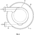
- the housing 26 includes an inlet opening 32, shown in the end view of FIG. 2 , tangential to an outer diameter of a pre-swirl chamber 34, also shown in FIG. 2 .
- the motor 12 is mounted to the housing 26 and drives the shaft 14 about the longitudinal axis 30.
- the motor 12 is a canned electric motor.
- a canned electric motor 12 is only one possible means of rotating the shaft 14.
- the shaft 14 may be driven by alternate methods, such as being driven by a hydraulic pump or other adjacent apparatus. While in the embodiment illustrated in FIG. 1 , the housing 26 is stationary and the shaft 14 rotates about the longitudinal axis 30, in other embodiments the configuration is reversed and the shaft 14 is stationary while the housing 26 rotates about the longitudinal axis 30.
- Bearing assemblies 36 support the shaft 14 for rotation about the longitudinal axis 30.
- the bearing assemblies 36 are magnetic bearings. Magnetic bearings utilize magnetic levitation to support the shaft 14 without physical contact.
- the bearing assemblies 36 include radial bearings 38 located at a first shaft end 40 and at a second shaft end 42 to maintain a desired radial position of the shaft 14 relative to the longitudinal axis 30.
- the radial bearings 38 include a radial bearing rotor 44 disposed at the shaft 14 and rotatable with the shaft 14, and an electromagnetic bearing stator 46 disposed at the housing 26, such that when the bearing stator 46 is electrically energized, the shaft 14 is levitated to its operational radial position, such as shown in FIG.
- FIG. 1 and in a cross-sectional view of a bearing assembly as shown in FIG. 3 .
- the motor 12 and the radial bearing rotor 44 are located inside the housing 26, while the radial bearing stator 46 is located outside of the housing 26. While two radial bearings 38 are illustrated in FIG. 1 , it is to be appreciated that other quantities of radial bearings 38, such as three or more radial bearings 38, may be utilized.
- the bearing assemblies 36 further include an axial bearing 48 configured to maintain a desired axial position of the shaft 14 relative to the housing 26.
- the axial bearing 48 is located at the second shaft end 42 such as shown in FIG. 1 , but one skilled in the art will readily appreciate that the axial bearing 48 may be located at other positions along the shaft 14.
- the axial bearing 48 includes axial bearing rotor elements 50 located at the shaft 14 and rotatable with the shaft 14.
- Axial bearing stator elements 52 are located upstream of the axial bearing rotor elements 50 and downstream of the axial bearing rotor elements 50, relative to the longitudinal axis 30. When electrically energized, the shaft 14 is maintained operational axial position along the longitudinal axis 30, such as shown in FIG. 1 .
- the axial bearing rotor elements 50 are located inside the housing 26, while the axial bearing stator elements 52 are located outside of the housing 26.
- Locating the radial bearing stator 46 and the axial bearing stator elements 52 outside of the housing 26, while the motor 12, the radial bearing rotor 44 and the axial bearing rotor elements 50 are located inside the housing 26 allows for the motor 12 and the bearing assemblies 36 to be "canned” or sealed, reducing leakage from the separator 10 or isolation of hazardous fluids internal to the separator 10.
- the bearing assemblies 36 are actively controlled and connected to a bearing controller 54.
- the bearing controller 54 may utilize, for example, position sensor data, to selectably alter the electrical signal to the radial bearing stator 46 and/or the axial bearing stator elements 52 to modify a radial and/or axial position of the shaft 14 during operation of the separator 10.
- the liquid/gas mixture enters the separator chamber 28 through the inlet opening 32 in a tangential manner, best shown in FIG. 2 .
- the liquid/gas mixture then enters the separator chamber 28 and flows past the disks 16 of the plurality of disks 16 axially along the separator chamber 28.
- the motor 12 rotates the shaft 14 and thereby the disks 16 about the longitudinal axis 30 mixture.
- the gas is displaced by the liquid and thereby moves toward the longitudinal axis 30 to form the gas core 24.
- the liquid moves toward the outer diameter 20 of the separator chamber 28 to form the liquid ring 22.
- the rotation of the disks 16 and cylinders 18 maintains the incoming rotation of the liquid portion of the mixture along the outer diameter 20 of the separator chamber 28. Rotation of the disks 16 and cylinders 18 generates a centrifugal force that drives the liquid toward the outer diameter 20 of the separator chamber 28 away from the longitudinal axis 30.
- the gas core 24 forms because the heavier liquid displaces the lighter gas to form the gas core 24 within the liquid ring 22.
- Gas flows through openings 58 in the disks 16 and may exit the separator chamber 28 via, for example, a hollow shaft portion 60 of the shaft 14 and out of a gas outlet 62. Liquid from the liquid ring exits the separator chamber 28 via a liquid outlet 64 (shown in FIG. 2 ).
- magnetic bearing assemblies 36 as one or more of the bearing assemblies 36 of the rotary separator 10 allows for the separator chamber 28 to be hermetically sealed. Further, the use of magnetic bearing assemblies 36 results in minimal friction and wear from the load bearing elements of the bearing assemblies 36, and improved performance of the bearing assemblies 36 while experiencing external loads, such as launch loads. Additionally or alternatively, the use of magnetic bearing assemblies 36 reduce vibration emissions and maintenance required as well as extends the service life of the rotary separator 10 and removes the need for lubrication of bearing assemblies. Magnetic bearing assemblies 36 can be used in harsh environmental conditions, including extremely low temperatures, low pressures, micro gravity conditions, and corrosive environments. A wide range of running speeds may be used, including ultra high speed rotation.
Landscapes
- Chemical & Material Sciences (AREA)
- Chemical Kinetics & Catalysis (AREA)
- Engineering & Computer Science (AREA)
- General Engineering & Computer Science (AREA)
- Mechanical Engineering (AREA)
- Magnetic Bearings And Hydrostatic Bearings (AREA)
- Centrifugal Separators (AREA)
Abstract
Description
- Exemplary embodiments pertain to the art of space vehicles and habitats, and, in particular, to phase separators of space vehicles and space habitats.
- The shift towards deep-space, long-duration missions, and the increase in commercialization of space travel motivate the need for technology useful for such long-duration travel. Space applications require accommodating a wide variety of flow compositions, minimizing or eliminating leakage, running at a wide and varying range of speeds, maximizing design life with minimal maintenance, and other unique challenges that the current commercial rotary phase separators cannot meet.
- In one embodiment, a rotary phase separator for a space environment includes a housing defining a separator chamber therein and a shaft located along a longitudinal axis of the rotary phase separator and inside the housing. Relative motion between the housing and the shaft about the longitudinal axis urging separation of gas and liquid from a two-phase liquid and gas fluid in the separator chamber. One or more magnetic bearing assemblies are supportive of the shaft relative to the housing.
- Additionally or alternatively, in this or other embodiments a plurality of discs are positioned along the shaft and are rotatable about the longitudinal axis with the shaft. The plurality of discs are configured to urge separation of the gas and liquid from the two-phase liquid and gas fluid in the separator chamber
- Additionally or alternatively, in this or other embodiments the one or more magnetic bearing assemblies includes at least one radial bearing assembly and an axial bearing assembly.
- Additionally or alternatively, in this or other embodiments the at least one radial bearing assembly is two radial bearing assemblies.
- Additionally or alternatively, in this or other embodiments each radial bearing assembly includes a radial bearing rotor located at the shaft, and a radial bearing stator located at the housing.
- Additionally or alternatively, in this or other embodiments the radial bearing stator is located outside of the housing.
- Additionally or alternatively, in this or other embodiments a first radial bearing assembly of the at least one radial bearing assembly is located at a first shaft end and a second radial bearing assembly of the at least one radial bearing assembly is located at a second shaft end opposite the first shaft end.
- Additionally or alternatively, in this or other embodiments the axial bearing assembly includes an axial bearing rotor element located at the shaft, and a plurality of axial bearing stator elements located upstream and downstream of the axial bearing rotor element, relative to the longitudinal axis.
- Additionally or alternatively, in this or other embodiments the plurality of axial bearing stator elements is located outside of the housing.
- Additionally or alternatively, in this or other embodiments the one or more magnetic bearings are actively controlled by a bearing controller.
- Additionally or alternatively, in this or other embodiments the shaft is driven by a motor located in the housing.
- In another embodiment, a rotary phase separator includes a housing defining a separator chamber therein, and a shaft located at a longitudinal axis of the rotary phase separator and rotatable about the longitudinal axis. A plurality of discs are positioned along the shaft and are rotatable about the longitudinal axis with the shaft. The plurality of discs are configured to urge separation of gas and liquid from a two-phase liquid and gas fluid in the separator chamber. One or more magnetic bearing assemblies are supportive of the shaft. Each magnetic bearing assembly includes a bearing rotor element, and a bearing stator element magnetically interactive with the bearing rotor element to support the shaft. The bearing rotor element is located in the housing and the bearing stator element is located outside of the housing.
- Additionally or alternatively, in this or other embodiments the one or more magnetic bearing assemblies includes at least one radial bearing assembly and an axial bearing assembly.
- Additionally or alternatively, in this or other embodiments the at least one radial bearing assembly is two radial bearing assemblies.
- Additionally or alternatively, in this or other embodiments a first radial bearing assembly of the at least one radial bearing assembly is located at a first shaft end and a second radial bearing assembly of the at least one radial bearing assembly is located at a second shaft end opposite the first shaft end.
- Additionally or alternatively, in this or other embodiments the axial bearing assembly includes an axial bearing rotor element located at the shaft, and a plurality of axial bearing stator elements located upstream and downstream of the axial bearing rotor element, relative to the longitudinal axis.
- Additionally or alternatively, in this or other embodiments the one or more magnetic bearings are actively controlled by a bearing controller.
- Additionally or alternatively, in this or other embodiments the shaft is driven by a motor located in the housing.
- The following descriptions should not be considered limiting in any way. With reference to the accompanying drawings, like elements are numbered alike:
-
FIG. 1 is a cross-sectional view of an embodiment of a magnetic bearing rotary phase separator; -
FIG. 2 is an end view of an embodiment of a magnetic bearing rotary phase separator; and -
FIG. 3 is a cross-sectional view of an embodiment of a radial bearing assembly. - A detailed description of one or more embodiments of the disclosed apparatus and method are presented herein by way of exemplification and not limitation with reference to the Figures.
- The present disclosure incorporates magnetic bearings as one or all of the bearing elements in a rotary separator. The term magnetic bearing includes actively controlled or passive magnetic bearings. The magnetic bearings in these configurations may also be canned, which allows for the ability to hermetically seal the separator. Magnetic bearing rotary phase separators minimize wear, improve external load performance, reduce maintenance, extend life, remove the need for lubricant, accommodate a wide range of running speeds, and allow for easily measured and readily changed dynamic properties. They can also be used in harsh environmental conditions, including extremely low temperatures, zero-gravity, and corrosive environments.
- Referring to the Figures, a cross-sectional view of an embodiment of a magnetic bearing
rotary phase separator 10 is shown inFIG. 1 . Therotary phase separator 10 separates phases of the liquid/gas mixture by using amotor 12 to drive ashaft 14 having a plurality ofdisks 16 andcylinders 18 that contact the liquid/gas mixture to spin the liquid such that centrifugal force drives the liquid toward anouter diameter 20 thereby creating aliquid ring 22 that displaces gas. The gas then migrates toward the center to create agas core 24. The liquid and gas are then exhausted from the chamber through separate outlet ports. - The
rotary phase separator 10 includes ahousing 26 that defines aseparator chamber 28 inside of thehousing 26. In some embodiments, theseparator chamber 28 is cylindrical with theouter diameter 20 concentric about alongitudinal axis 30 of thehousing 26. Thehousing 26 includes an inlet opening 32, shown in the end view ofFIG. 2 , tangential to an outer diameter of apre-swirl chamber 34, also shown inFIG. 2 . - The
motor 12 is mounted to thehousing 26 and drives theshaft 14 about thelongitudinal axis 30. In some embodiments, themotor 12 is a canned electric motor. One skilled in the art will readily appreciate that a cannedelectric motor 12 is only one possible means of rotating theshaft 14. Theshaft 14 may be driven by alternate methods, such as being driven by a hydraulic pump or other adjacent apparatus. While in the embodiment illustrated inFIG. 1 , thehousing 26 is stationary and theshaft 14 rotates about thelongitudinal axis 30, in other embodiments the configuration is reversed and theshaft 14 is stationary while thehousing 26 rotates about thelongitudinal axis 30. -
Bearing assemblies 36 support theshaft 14 for rotation about thelongitudinal axis 30. Thebearing assemblies 36 are magnetic bearings. Magnetic bearings utilize magnetic levitation to support theshaft 14 without physical contact. Thebearing assemblies 36 includeradial bearings 38 located at afirst shaft end 40 and at asecond shaft end 42 to maintain a desired radial position of theshaft 14 relative to thelongitudinal axis 30. Theradial bearings 38 include a radial bearingrotor 44 disposed at theshaft 14 and rotatable with theshaft 14, and anelectromagnetic bearing stator 46 disposed at thehousing 26, such that when thebearing stator 46 is electrically energized, theshaft 14 is levitated to its operational radial position, such as shown inFIG. 1 and in a cross-sectional view of a bearing assembly as shown inFIG. 3 . In some embodiments, themotor 12 and the radial bearingrotor 44 are located inside thehousing 26, while the radial bearingstator 46 is located outside of thehousing 26. While tworadial bearings 38 are illustrated inFIG. 1 , it is to be appreciated that other quantities ofradial bearings 38, such as three or moreradial bearings 38, may be utilized. - The
bearing assemblies 36 further include an axial bearing 48 configured to maintain a desired axial position of theshaft 14 relative to thehousing 26. In some embodiments, the axial bearing 48 is located at thesecond shaft end 42 such as shown inFIG. 1 , but one skilled in the art will readily appreciate that theaxial bearing 48 may be located at other positions along theshaft 14. Theaxial bearing 48 includes axialbearing rotor elements 50 located at theshaft 14 and rotatable with theshaft 14. Axial bearingstator elements 52 are located upstream of the axialbearing rotor elements 50 and downstream of the axialbearing rotor elements 50, relative to thelongitudinal axis 30. When electrically energized, theshaft 14 is maintained operational axial position along thelongitudinal axis 30, such as shown inFIG. 1 . In some embodiments, the axialbearing rotor elements 50 are located inside thehousing 26, while the axialbearing stator elements 52 are located outside of thehousing 26. - Locating the
radial bearing stator 46 and the axialbearing stator elements 52 outside of thehousing 26, while themotor 12, theradial bearing rotor 44 and the axialbearing rotor elements 50 are located inside thehousing 26 allows for themotor 12 and thebearing assemblies 36 to be "canned" or sealed, reducing leakage from theseparator 10 or isolation of hazardous fluids internal to theseparator 10. - In some embodiments, such as shown in
FIG. 1 , the bearingassemblies 36 are actively controlled and connected to a bearing controller 54. The bearing controller 54 may utilize, for example, position sensor data, to selectably alter the electrical signal to theradial bearing stator 46 and/or the axialbearing stator elements 52 to modify a radial and/or axial position of theshaft 14 during operation of theseparator 10. - In operation, the liquid/gas mixture enters the
separator chamber 28 through the inlet opening 32 in a tangential manner, best shown inFIG. 2 . The liquid/gas mixture then enters theseparator chamber 28 and flows past thedisks 16 of the plurality ofdisks 16 axially along theseparator chamber 28. - The
motor 12 rotates theshaft 14 and thereby thedisks 16 about thelongitudinal axis 30 mixture. As the liquid/gas mixture flows around thedisks 16 the gas is displaced by the liquid and thereby moves toward thelongitudinal axis 30 to form thegas core 24. The liquid moves toward theouter diameter 20 of theseparator chamber 28 to form theliquid ring 22. The rotation of thedisks 16 andcylinders 18 maintains the incoming rotation of the liquid portion of the mixture along theouter diameter 20 of theseparator chamber 28. Rotation of thedisks 16 andcylinders 18 generates a centrifugal force that drives the liquid toward theouter diameter 20 of theseparator chamber 28 away from thelongitudinal axis 30. Thegas core 24 forms because the heavier liquid displaces the lighter gas to form thegas core 24 within theliquid ring 22. Gas flows throughopenings 58 in thedisks 16 and may exit theseparator chamber 28 via, for example, ahollow shaft portion 60 of theshaft 14 and out of agas outlet 62. Liquid from the liquid ring exits theseparator chamber 28 via a liquid outlet 64 (shown inFIG. 2 ). - The incorporation of
magnetic bearing assemblies 36 as one or more of thebearing assemblies 36 of therotary separator 10 allows for theseparator chamber 28 to be hermetically sealed. Further, the use ofmagnetic bearing assemblies 36 results in minimal friction and wear from the load bearing elements of thebearing assemblies 36, and improved performance of thebearing assemblies 36 while experiencing external loads, such as launch loads. Additionally or alternatively, the use ofmagnetic bearing assemblies 36 reduce vibration emissions and maintenance required as well as extends the service life of therotary separator 10 and removes the need for lubrication of bearing assemblies.Magnetic bearing assemblies 36 can be used in harsh environmental conditions, including extremely low temperatures, low pressures, micro gravity conditions, and corrosive environments. A wide range of running speeds may be used, including ultra high speed rotation. - The term "about" is intended to include the degree of error associated with measurement of the particular quantity based upon the equipment available at the time of filing the application.
- The terminology used herein is for the purpose of describing particular embodiments only and is not intended to be limiting of the present disclosure. As used herein, the singular forms "a", "an" and "the" are intended to include the plural forms as well, unless the context clearly indicates otherwise. It will be further understood that the terms "comprises" and/or "comprising," when used in this specification, specify the presence of stated features, integers, steps, operations, elements, and/or components, but do not preclude the presence or addition of one or more other features, integers, steps, operations, element components, and/or groups thereof.
- While the present disclosure has been described with reference to an exemplary embodiment or embodiments, it will be understood by those skilled in the art that various changes may be made and equivalents may be substituted for elements thereof without departing from the scope of the present disclosure. In addition, many modifications may be made to adapt a particular situation or material to the teachings of the present disclosure without departing from the essential scope thereof. Therefore, it is intended that the present disclosure not be limited to the particular embodiment disclosed as the best mode contemplated for carrying out this present disclosure, but that the present disclosure will include all embodiments falling within the scope of the claims.
Claims (15)
- A rotary phase separator for a space environment, comprising:a housing (26) defining a separator chamber therein;a shaft (14) disposed along a longitudinal axis of the rotary phase separator inside of the housing (26), relative motion between the housing (26) and the shaft (14) about the longitudinal axis urging separation of gas and liquid from a two-phase liquid and gas fluid in the separator chamber; andone or more magnetic bearing assemblies (36) supportive of the shaft (14) relative to the housing (26).
- The rotary phase separator of claim 1, further comprising a plurality of discs positioned along the shaft (14) and rotatable about the longitudinal axis with the shaft (14), the plurality of discs configured to urge separation of the gas and liquid from the two-phase liquid and gas fluid in the separator chamber
- The rotary phase separator of claim 1 or 2, wherein the one or more magnetic bearing assemblies (36) includes at least one radial bearing assembly and an axial bearing assembly.
- The rotary phase separator of claim 3, wherein the at least one radial bearing assembly is two radial bearing assemblies (36).
- The rotary phase separator of claim 3, wherein each radial bearing assembly includes:a radial bearing rotor disposed at the shaft (14); anda radial bearing stator disposed at the housing (26).
- The rotary phase separator of claim 5, wherein the radial bearing stator is disposed outside of the housing (26).
- The rotary phase separator of claim 3, wherein a first radial bearing assembly of the at least one radial bearing assembly is disposed at a first shaft end and a second radial bearing assembly of the at least one radial bearing assembly is disposed at a second shaft (14) end opposite the first shaft end.
- The rotary phase separator of claim 3, wherein the axial bearing assembly includes:an axial bearing rotor element disposed at the shaft (14); anda plurality of axial bearing stator elements disposed upstream and downstream of the axial bearing rotor element, relative to the longitudinal axis, and optionallywherein the plurality of axial bearing stator elements is disposed outside of the housing (26).
- The rotary phase separator of any preceding claim, wherein the one or more magnetic bearings are actively controlled by a bearing controller, and/or wherein the shaft (14) is driven by a motor disposed in the housing (26).
- A rotary phase separator, comprising:a housing (26) defining a separator chamber therein;a shaft (14) disposed at a longitudinal axis of the rotary phase separator and rotatable about the longitudinal axis;a plurality of discs positioned along the shaft (14) and rotatable about the longitudinal axis with the shaft (14), the plurality of discs configured to urge separation of gas and liquid from a two-phase liquid and gas fluid in the separator chamber; andone or more magnetic bearing assemblies (36) supportive of the shaft (14), each magnetic bearing assembly includinga bearing rotor element; anda bearing stator element magnetically interactive with the bearing rotor element to support the shaft (14);wherein the bearing rotor element is disposed in the housing (26) and the bearing stator element is disposed outside of the housing (26).
- The rotary phase separator of claim 10, wherein the one or more magnetic bearing assemblies (36) includes at least one radial bearing assembly and an axial bearing assembly.
- The rotary phase separator of claim 11, wherein the at least one radial bearing assembly is two radial bearing assemblies (36).
- The rotary phase separator of claim 11, wherein a first radial bearing assembly of the at least one radial bearing assembly is disposed at a first shaft end and a second radial bearing assembly of the at least one radial bearing assembly is disposed at a second shaft end opposite the first shaft end.
- The rotary phase separator of claim 11, wherein the axial bearing assembly includes:an axial bearing rotor element disposed at the shaft (14); anda plurality of axial bearing stator elements disposed upstream and downstream of the axial bearing rotor element, relative to the longitudinal axis.
- The rotary phase separator of any of claims 10 to 13, wherein the one or more magnetic bearings are actively controlled by a bearing controller, and/or
wherein the shaft (14) is driven by a motor disposed in the housing (26).
Applications Claiming Priority (1)
| Application Number | Priority Date | Filing Date | Title |
|---|---|---|---|
| US17/412,751 US11859666B2 (en) | 2021-08-26 | 2021-08-26 | Rotary phase separator with magnetic bearing |
Publications (2)
| Publication Number | Publication Date |
|---|---|
| EP4140563A1 true EP4140563A1 (en) | 2023-03-01 |
| EP4140563B1 EP4140563B1 (en) | 2025-04-09 |
Family
ID=82851840
Family Applications (1)
| Application Number | Title | Priority Date | Filing Date |
|---|---|---|---|
| EP22189515.4A Active EP4140563B1 (en) | 2021-08-26 | 2022-08-09 | Rotary phase separator with magnetic bearing |
Country Status (3)
| Country | Link |
|---|---|
| US (1) | US11859666B2 (en) |
| EP (1) | EP4140563B1 (en) |
| CN (1) | CN115888192A (en) |
Families Citing this family (1)
| Publication number | Priority date | Publication date | Assignee | Title |
|---|---|---|---|---|
| CN116651015A (en) * | 2023-05-30 | 2023-08-29 | 中国科学院上海应用物理研究所 | Centrifugal extractor and centrifugal extraction system comprising same |
Citations (4)
| Publication number | Priority date | Publication date | Assignee | Title |
|---|---|---|---|---|
| US20030000184A1 (en) * | 2001-07-02 | 2003-01-02 | Dean W. Clark | Rotary phase separator with integral accumulator and outlet valve |
| WO2012057885A1 (en) * | 2010-10-27 | 2012-05-03 | Dresser-Rand Company | Multiple motor drivers for a hermetically-sealed motor-compressor system |
| US20120151887A1 (en) * | 2009-06-11 | 2012-06-21 | Ntnu Technology Transfer As | Separator for a gas/liquid flow |
| US20150104290A1 (en) * | 2013-10-15 | 2015-04-16 | Dresser-Rand Company | Supersonic compressor with separator |
Family Cites Families (11)
| Publication number | Priority date | Publication date | Assignee | Title |
|---|---|---|---|---|
| GB1302044A (en) | 1969-04-10 | 1973-01-04 | ||
| JPH11506390A (en) | 1995-06-03 | 1999-06-08 | キュードス・セントリフュージ・リミテッド | Gas centrifuge |
| EP0899857B1 (en) * | 1997-08-25 | 2007-11-28 | LUST ANTRIEBSTECHNIK GmbH | Rotary device with magnetic bearing |
| JP3930170B2 (en) * | 1998-02-18 | 2007-06-13 | 株式会社荏原製作所 | Circulation fan device |
| US6592654B2 (en) | 2001-06-25 | 2003-07-15 | Cryogenic Group Inc. | Liquid extraction and separation method for treating fluids utilizing flow swirl |
| DE102008062160A1 (en) * | 2008-12-13 | 2010-07-08 | Schaeffler Technologies Gmbh & Co. Kg | decanter centrifuge |
| US8657935B2 (en) | 2010-07-20 | 2014-02-25 | Dresser-Rand Company | Combination of expansion and cooling to enhance separation |
| EP3182559B1 (en) * | 2015-12-14 | 2018-01-31 | Siemens Aktiengesellschaft | Rotor alignment for reducing vibrations and noises |
| CN114876825A (en) * | 2017-03-24 | 2022-08-09 | 江森自控泰科知识产权控股有限责任合伙公司 | Magnetic bearing motor compressor |
| FI128651B (en) * | 2017-06-30 | 2020-09-30 | Lappeenrannan Teknillinen Yliopisto | System for an electric machine |
| CN109281863A (en) * | 2018-11-21 | 2019-01-29 | 珠海格力电器股份有限公司 | A new type of magnetic levitation compressor structure |
-
2021
- 2021-08-26 US US17/412,751 patent/US11859666B2/en active Active
-
2022
- 2022-07-08 CN CN202210827938.5A patent/CN115888192A/en active Pending
- 2022-08-09 EP EP22189515.4A patent/EP4140563B1/en active Active
Patent Citations (4)
| Publication number | Priority date | Publication date | Assignee | Title |
|---|---|---|---|---|
| US20030000184A1 (en) * | 2001-07-02 | 2003-01-02 | Dean W. Clark | Rotary phase separator with integral accumulator and outlet valve |
| US20120151887A1 (en) * | 2009-06-11 | 2012-06-21 | Ntnu Technology Transfer As | Separator for a gas/liquid flow |
| WO2012057885A1 (en) * | 2010-10-27 | 2012-05-03 | Dresser-Rand Company | Multiple motor drivers for a hermetically-sealed motor-compressor system |
| US20150104290A1 (en) * | 2013-10-15 | 2015-04-16 | Dresser-Rand Company | Supersonic compressor with separator |
Also Published As
| Publication number | Publication date |
|---|---|
| EP4140563B1 (en) | 2025-04-09 |
| CN115888192A (en) | 2023-04-04 |
| US11859666B2 (en) | 2024-01-02 |
| US20230061705A1 (en) | 2023-03-02 |
Similar Documents
| Publication | Publication Date | Title |
|---|---|---|
| US5059092A (en) | Vacuum pump having emergency bearings | |
| US5577883A (en) | Gas friction vacuum pump having a cooling system | |
| US6043580A (en) | Rotodynamic machine for the forwarding of a fluid | |
| FI66056C (en) | SEPARERINGSMASKIN | |
| US9341191B2 (en) | Thrust equalizing mechanism for cryogenic turbine generator | |
| US3326453A (en) | Gas-bearing assembly | |
| US9714661B2 (en) | Vacuum pump | |
| CA3080479C (en) | Electrical discharge prevention in bearing for submersible pump motor | |
| CA1084459A (en) | Liquid ring pumps and compressors using a ferrofluidic ring liquid | |
| US11859666B2 (en) | Rotary phase separator with magnetic bearing | |
| WO2012145486A2 (en) | Magnetic bearing system for heavy loaded compressor | |
| US6050782A (en) | Magnetically suspended high velocity vacuum pump | |
| US7629715B1 (en) | Systems, devices and methods for driving machinery | |
| US6547862B2 (en) | Rotary phase separator with integral accumulator and outlet valve | |
| US3972653A (en) | In-line pump device | |
| JP2022536225A5 (en) | ||
| JP2022536225A (en) | Unlubricated centrifugal compressor | |
| EP0147015A2 (en) | Turbomolecular pump and bearing assembly therefor | |
| KR101998010B1 (en) | Disk stack centrifuge | |
| CN216343036U (en) | Magnetic suspension hydrogen circulating pump | |
| EP4108959A1 (en) | Noncontacting intershaft seal system | |
| CA1173872A (en) | Plural fluid magnetic/centrifugal seal | |
| CN113606163A (en) | Hydrogen Circulation Pump | |
| Brune et al. | Application of active magnetic bearings in turbocompressors and turboexpanders of the gas industry | |
| CN222333975U (en) | Compression piston assembly and rotary Stirling refrigerator |
Legal Events
| Date | Code | Title | Description |
|---|---|---|---|
| PUAI | Public reference made under article 153(3) epc to a published international application that has entered the european phase |
Free format text: ORIGINAL CODE: 0009012 |
|
| STAA | Information on the status of an ep patent application or granted ep patent |
Free format text: STATUS: THE APPLICATION HAS BEEN PUBLISHED |
|
| AK | Designated contracting states |
Kind code of ref document: A1 Designated state(s): AL AT BE BG CH CY CZ DE DK EE ES FI FR GB GR HR HU IE IS IT LI LT LU LV MC MK MT NL NO PL PT RO RS SE SI SK SM TR |
|
| STAA | Information on the status of an ep patent application or granted ep patent |
Free format text: STATUS: REQUEST FOR EXAMINATION WAS MADE |
|
| 17P | Request for examination filed |
Effective date: 20230821 |
|
| RBV | Designated contracting states (corrected) |
Designated state(s): AL AT BE BG CH CY CZ DE DK EE ES FI FR GB GR HR HU IE IS IT LI LT LU LV MC MK MT NL NO PL PT RO RS SE SI SK SM TR |
|
| STAA | Information on the status of an ep patent application or granted ep patent |
Free format text: STATUS: EXAMINATION IS IN PROGRESS |
|
| 17Q | First examination report despatched |
Effective date: 20231115 |
|
| GRAP | Despatch of communication of intention to grant a patent |
Free format text: ORIGINAL CODE: EPIDOSNIGR1 |
|
| STAA | Information on the status of an ep patent application or granted ep patent |
Free format text: STATUS: GRANT OF PATENT IS INTENDED |
|
| INTG | Intention to grant announced |
Effective date: 20241106 |
|
| RIN1 | Information on inventor provided before grant (corrected) |
Inventor name: NAGPAL, ARJUN Inventor name: FRAZIER, MIGUEL Inventor name: KAUFMAN, CORY Inventor name: HIMMELMANN, ASHLEY ROSE |
|
| GRAS | Grant fee paid |
Free format text: ORIGINAL CODE: EPIDOSNIGR3 |
|
| GRAA | (expected) grant |
Free format text: ORIGINAL CODE: 0009210 |
|
| STAA | Information on the status of an ep patent application or granted ep patent |
Free format text: STATUS: THE PATENT HAS BEEN GRANTED |
|
| AK | Designated contracting states |
Kind code of ref document: B1 Designated state(s): AL AT BE BG CH CY CZ DE DK EE ES FI FR GB GR HR HU IE IS IT LI LT LU LV MC MK MT NL NO PL PT RO RS SE SI SK SM TR |
|
| REG | Reference to a national code |
Ref country code: GB Ref legal event code: FG4D |
|
| REG | Reference to a national code |
Ref country code: CH Ref legal event code: EP |
|
| REG | Reference to a national code |
Ref country code: DE Ref legal event code: R096 Ref document number: 602022012811 Country of ref document: DE |
|
| REG | Reference to a national code |
Ref country code: IE Ref legal event code: FG4D |
|
| REG | Reference to a national code |
Ref country code: NL Ref legal event code: MP Effective date: 20250409 |
|
| PG25 | Lapsed in a contracting state [announced via postgrant information from national office to epo] |
Ref country code: NL Free format text: LAPSE BECAUSE OF FAILURE TO SUBMIT A TRANSLATION OF THE DESCRIPTION OR TO PAY THE FEE WITHIN THE PRESCRIBED TIME-LIMIT Effective date: 20250409 |
|
| REG | Reference to a national code |
Ref country code: AT Ref legal event code: MK05 Ref document number: 1783063 Country of ref document: AT Kind code of ref document: T Effective date: 20250409 |
|
| PG25 | Lapsed in a contracting state [announced via postgrant information from national office to epo] |
Ref country code: FI Free format text: LAPSE BECAUSE OF FAILURE TO SUBMIT A TRANSLATION OF THE DESCRIPTION OR TO PAY THE FEE WITHIN THE PRESCRIBED TIME-LIMIT Effective date: 20250409 Ref country code: PT Free format text: LAPSE BECAUSE OF FAILURE TO SUBMIT A TRANSLATION OF THE DESCRIPTION OR TO PAY THE FEE WITHIN THE PRESCRIBED TIME-LIMIT Effective date: 20250811 Ref country code: ES Free format text: LAPSE BECAUSE OF FAILURE TO SUBMIT A TRANSLATION OF THE DESCRIPTION OR TO PAY THE FEE WITHIN THE PRESCRIBED TIME-LIMIT Effective date: 20250409 |
|
| PGFP | Annual fee paid to national office [announced via postgrant information from national office to epo] |
Ref country code: DE Payment date: 20250724 Year of fee payment: 4 |
|
| REG | Reference to a national code |
Ref country code: LT Ref legal event code: MG9D |
|
| PG25 | Lapsed in a contracting state [announced via postgrant information from national office to epo] |
Ref country code: GR Free format text: LAPSE BECAUSE OF FAILURE TO SUBMIT A TRANSLATION OF THE DESCRIPTION OR TO PAY THE FEE WITHIN THE PRESCRIBED TIME-LIMIT Effective date: 20250710 Ref country code: NO Free format text: LAPSE BECAUSE OF FAILURE TO SUBMIT A TRANSLATION OF THE DESCRIPTION OR TO PAY THE FEE WITHIN THE PRESCRIBED TIME-LIMIT Effective date: 20250709 |
|
| PG25 | Lapsed in a contracting state [announced via postgrant information from national office to epo] |
Ref country code: PL Free format text: LAPSE BECAUSE OF FAILURE TO SUBMIT A TRANSLATION OF THE DESCRIPTION OR TO PAY THE FEE WITHIN THE PRESCRIBED TIME-LIMIT Effective date: 20250409 |
|
| PG25 | Lapsed in a contracting state [announced via postgrant information from national office to epo] |
Ref country code: BG Free format text: LAPSE BECAUSE OF FAILURE TO SUBMIT A TRANSLATION OF THE DESCRIPTION OR TO PAY THE FEE WITHIN THE PRESCRIBED TIME-LIMIT Effective date: 20250409 |
|
| PG25 | Lapsed in a contracting state [announced via postgrant information from national office to epo] |
Ref country code: HR Free format text: LAPSE BECAUSE OF FAILURE TO SUBMIT A TRANSLATION OF THE DESCRIPTION OR TO PAY THE FEE WITHIN THE PRESCRIBED TIME-LIMIT Effective date: 20250409 |
|
| PG25 | Lapsed in a contracting state [announced via postgrant information from national office to epo] |
Ref country code: AT Free format text: LAPSE BECAUSE OF FAILURE TO SUBMIT A TRANSLATION OF THE DESCRIPTION OR TO PAY THE FEE WITHIN THE PRESCRIBED TIME-LIMIT Effective date: 20250409 |
|
| PGFP | Annual fee paid to national office [announced via postgrant information from national office to epo] |
Ref country code: FR Payment date: 20250725 Year of fee payment: 4 |
|
| PG25 | Lapsed in a contracting state [announced via postgrant information from national office to epo] |
Ref country code: RS Free format text: LAPSE BECAUSE OF FAILURE TO SUBMIT A TRANSLATION OF THE DESCRIPTION OR TO PAY THE FEE WITHIN THE PRESCRIBED TIME-LIMIT Effective date: 20250709 |
|
| PG25 | Lapsed in a contracting state [announced via postgrant information from national office to epo] |
Ref country code: IS Free format text: LAPSE BECAUSE OF FAILURE TO SUBMIT A TRANSLATION OF THE DESCRIPTION OR TO PAY THE FEE WITHIN THE PRESCRIBED TIME-LIMIT Effective date: 20250809 |
|
| PG25 | Lapsed in a contracting state [announced via postgrant information from national office to epo] |
Ref country code: LV Free format text: LAPSE BECAUSE OF FAILURE TO SUBMIT A TRANSLATION OF THE DESCRIPTION OR TO PAY THE FEE WITHIN THE PRESCRIBED TIME-LIMIT Effective date: 20250409 |
|
| REG | Reference to a national code |
Ref country code: DE Ref legal event code: R097 Ref document number: 602022012811 Country of ref document: DE |
|
| PG25 | Lapsed in a contracting state [announced via postgrant information from national office to epo] |
Ref country code: DK Free format text: LAPSE BECAUSE OF FAILURE TO SUBMIT A TRANSLATION OF THE DESCRIPTION OR TO PAY THE FEE WITHIN THE PRESCRIBED TIME-LIMIT Effective date: 20250409 Ref country code: SM Free format text: LAPSE BECAUSE OF FAILURE TO SUBMIT A TRANSLATION OF THE DESCRIPTION OR TO PAY THE FEE WITHIN THE PRESCRIBED TIME-LIMIT Effective date: 20250409 |
|
| PG25 | Lapsed in a contracting state [announced via postgrant information from national office to epo] |
Ref country code: CZ Free format text: LAPSE BECAUSE OF FAILURE TO SUBMIT A TRANSLATION OF THE DESCRIPTION OR TO PAY THE FEE WITHIN THE PRESCRIBED TIME-LIMIT Effective date: 20250409 |
|
| PG25 | Lapsed in a contracting state [announced via postgrant information from national office to epo] |
Ref country code: EE Free format text: LAPSE BECAUSE OF FAILURE TO SUBMIT A TRANSLATION OF THE DESCRIPTION OR TO PAY THE FEE WITHIN THE PRESCRIBED TIME-LIMIT Effective date: 20250409 |
|
| PG25 | Lapsed in a contracting state [announced via postgrant information from national office to epo] |
Ref country code: SK Free format text: LAPSE BECAUSE OF FAILURE TO SUBMIT A TRANSLATION OF THE DESCRIPTION OR TO PAY THE FEE WITHIN THE PRESCRIBED TIME-LIMIT Effective date: 20250409 |
|
| PG25 | Lapsed in a contracting state [announced via postgrant information from national office to epo] |
Ref country code: IT Free format text: LAPSE BECAUSE OF FAILURE TO SUBMIT A TRANSLATION OF THE DESCRIPTION OR TO PAY THE FEE WITHIN THE PRESCRIBED TIME-LIMIT Effective date: 20250409 |
|
| PG25 | Lapsed in a contracting state [announced via postgrant information from national office to epo] |
Ref country code: RO Free format text: LAPSE BECAUSE OF FAILURE TO SUBMIT A TRANSLATION OF THE DESCRIPTION OR TO PAY THE FEE WITHIN THE PRESCRIBED TIME-LIMIT Effective date: 20250409 |
|
| PLBE | No opposition filed within time limit |
Free format text: ORIGINAL CODE: 0009261 |
|
| STAA | Information on the status of an ep patent application or granted ep patent |
Free format text: STATUS: NO OPPOSITION FILED WITHIN TIME LIMIT |
|
| REG | Reference to a national code |
Ref country code: CH Ref legal event code: L10 Free format text: ST27 STATUS EVENT CODE: U-0-0-L10-L00 (AS PROVIDED BY THE NATIONAL OFFICE) Effective date: 20260218 |
|
| 26N | No opposition filed |
Effective date: 20260112 |
|
| REG | Reference to a national code |
Ref country code: CH Ref legal event code: H13 Free format text: ST27 STATUS EVENT CODE: U-0-0-H10-H13 (AS PROVIDED BY THE NATIONAL OFFICE) Effective date: 20260324 |
|
| PG25 | Lapsed in a contracting state [announced via postgrant information from national office to epo] |
Ref country code: MC Free format text: LAPSE BECAUSE OF FAILURE TO SUBMIT A TRANSLATION OF THE DESCRIPTION OR TO PAY THE FEE WITHIN THE PRESCRIBED TIME-LIMIT Effective date: 20250409 |
|
| PG25 | Lapsed in a contracting state [announced via postgrant information from national office to epo] |
Ref country code: LU Free format text: LAPSE BECAUSE OF NON-PAYMENT OF DUE FEES Effective date: 20250809 |
|
| PG25 | Lapsed in a contracting state [announced via postgrant information from national office to epo] |
Ref country code: CH Free format text: LAPSE BECAUSE OF NON-PAYMENT OF DUE FEES Effective date: 20250831 |