EP4140405B1 - Loop-type sampling device and breathalyzer comprising same - Google Patents
Loop-type sampling device and breathalyzer comprising same Download PDFInfo
- Publication number
- EP4140405B1 EP4140405B1 EP21791822.6A EP21791822A EP4140405B1 EP 4140405 B1 EP4140405 B1 EP 4140405B1 EP 21791822 A EP21791822 A EP 21791822A EP 4140405 B1 EP4140405 B1 EP 4140405B1
- Authority
- EP
- European Patent Office
- Prior art keywords
- sample gas
- loop
- coupling surface
- sampling device
- carbon dioxide
- Prior art date
- Legal status (The legal status is an assumption and is not a legal conclusion. Google has not performed a legal analysis and makes no representation as to the accuracy of the status listed.)
- Active
Links
Images



Classifications
-
- A—HUMAN NECESSITIES
- A61—MEDICAL OR VETERINARY SCIENCE; HYGIENE
- A61B—DIAGNOSIS; SURGERY; IDENTIFICATION
- A61B5/00—Measuring for diagnostic purposes; Identification of persons
- A61B5/08—Measuring devices for evaluating the respiratory organs
- A61B5/097—Devices for facilitating collection of breath or for directing breath into or through measuring devices
-
- G—PHYSICS
- G01—MEASURING; TESTING
- G01N—INVESTIGATING OR ANALYSING MATERIALS BY DETERMINING THEIR CHEMICAL OR PHYSICAL PROPERTIES
- G01N33/00—Investigating or analysing materials by specific methods not covered by groups G01N1/00 - G01N31/00
- G01N33/48—Biological material, e.g. blood, urine; Haemocytometers
- G01N33/483—Physical analysis of biological material
- G01N33/497—Physical analysis of biological material of gaseous biological material, e.g. breath
- G01N33/4972—Determining alcohol content
-
- A—HUMAN NECESSITIES
- A61—MEDICAL OR VETERINARY SCIENCE; HYGIENE
- A61B—DIAGNOSIS; SURGERY; IDENTIFICATION
- A61B10/00—Instruments for taking body samples for diagnostic purposes; Other methods or instruments for diagnosis, e.g. for vaccination diagnosis, sex determination or ovulation-period determination; Throat striking implements
-
- A—HUMAN NECESSITIES
- A61—MEDICAL OR VETERINARY SCIENCE; HYGIENE
- A61B—DIAGNOSIS; SURGERY; IDENTIFICATION
- A61B5/00—Measuring for diagnostic purposes; Identification of persons
- A61B5/08—Measuring devices for evaluating the respiratory organs
- A61B5/082—Evaluation by breath analysis, e.g. determination of the chemical composition of exhaled breath
-
- A—HUMAN NECESSITIES
- A61—MEDICAL OR VETERINARY SCIENCE; HYGIENE
- A61B—DIAGNOSIS; SURGERY; IDENTIFICATION
- A61B5/00—Measuring for diagnostic purposes; Identification of persons
- A61B5/48—Other medical applications
- A61B5/4845—Toxicology, e.g. by detection of alcohol, drug or toxic products
-
- G—PHYSICS
- G01—MEASURING; TESTING
- G01N—INVESTIGATING OR ANALYSING MATERIALS BY DETERMINING THEIR CHEMICAL OR PHYSICAL PROPERTIES
- G01N1/00—Sampling; Preparing specimens for investigation
- G01N1/02—Devices for withdrawing samples
- G01N1/22—Devices for withdrawing samples in the gaseous state
- G01N1/24—Suction devices
-
- G—PHYSICS
- G01—MEASURING; TESTING
- G01N—INVESTIGATING OR ANALYSING MATERIALS BY DETERMINING THEIR CHEMICAL OR PHYSICAL PROPERTIES
- G01N33/00—Investigating or analysing materials by specific methods not covered by groups G01N1/00 - G01N31/00
- G01N33/48—Biological material, e.g. blood, urine; Haemocytometers
- G01N33/483—Physical analysis of biological material
- G01N33/497—Physical analysis of biological material of gaseous biological material, e.g. breath
-
- A—HUMAN NECESSITIES
- A61—MEDICAL OR VETERINARY SCIENCE; HYGIENE
- A61B—DIAGNOSIS; SURGERY; IDENTIFICATION
- A61B10/00—Instruments for taking body samples for diagnostic purposes; Other methods or instruments for diagnosis, e.g. for vaccination diagnosis, sex determination or ovulation-period determination; Throat striking implements
- A61B2010/0009—Testing for drug or alcohol abuse
-
- A—HUMAN NECESSITIES
- A61—MEDICAL OR VETERINARY SCIENCE; HYGIENE
- A61B—DIAGNOSIS; SURGERY; IDENTIFICATION
- A61B10/00—Instruments for taking body samples for diagnostic purposes; Other methods or instruments for diagnosis, e.g. for vaccination diagnosis, sex determination or ovulation-period determination; Throat striking implements
- A61B2010/0083—Instruments for taking body samples for diagnostic purposes; Other methods or instruments for diagnosis, e.g. for vaccination diagnosis, sex determination or ovulation-period determination; Throat striking implements for taking gas samples
- A61B2010/0087—Breath samples
-
- G—PHYSICS
- G01—MEASURING; TESTING
- G01N—INVESTIGATING OR ANALYSING MATERIALS BY DETERMINING THEIR CHEMICAL OR PHYSICAL PROPERTIES
- G01N1/00—Sampling; Preparing specimens for investigation
- G01N1/02—Devices for withdrawing samples
- G01N1/22—Devices for withdrawing samples in the gaseous state
- G01N2001/2244—Exhaled gas, e.g. alcohol detecting
-
- G—PHYSICS
- G01—MEASURING; TESTING
- G01N—INVESTIGATING OR ANALYSING MATERIALS BY DETERMINING THEIR CHEMICAL OR PHYSICAL PROPERTIES
- G01N1/00—Sampling; Preparing specimens for investigation
- G01N1/02—Devices for withdrawing samples
- G01N1/22—Devices for withdrawing samples in the gaseous state
- G01N2001/2285—Details of probe structures
Definitions
- the present disclosure relates to a loop-type sampling device and a breathalyzer including the same. More particularly, the present disclosure relates to a loop-type sampling device and a breathalyzer including the loop-type sampling device that is capable of minimizing an infection caused by droplets included in an exhalation (exhaled gas) of a subject.
- a breathalyzer measures a concentration of alcohol that is exhaled together with an exhalation of a subject. Since the concentration of alcohol discharged together with the exhalation is proportional to a concentration of alcohol in blood, a blood alcohol concentration (BAC) is capable of being calculated when the concentration of alcohol contained in the exhalation is measured.
- BAC blood alcohol concentration
- an exhalation passage 2 formed in a cylindrical shape and coupled to a blowing tube 1 is used as a sampling device for collecting a part of the exhalation.
- the exhalation passage 2 has both ends that are open.
- the blowing tube 1 may be coupled to an inlet port of a first end of the exhalation passage 2.
- the exhalation introduced into the exhalation passage 2 through the blowing tube 1 is discharged to the outside through a discharge port of a second end of the exhalation passage 2.
- a collection hole 3 for supplying the part of the exhalation introduced into the exhalation passage 2 to an alcohol sensor 5 is formed in the exhalation passage 2.
- a suction pump 4 for introducing a sample gas to the alcohol sensor 5 is mounted on a rear end of the alcohol sensor 5.
- the gas sampling means include at least one length of tube and means to connect at least a first end of said tube to a central unit of a gas sampling system and/or a vacuum. At least part of the tube is formed from a porous material.
- the porous material is provided with a substantially even draw / suction / vacuum and/or the like through pores of the said porous material along substantially the length of the same.
- Document KR 101 873 642 B1 relates to a composite gas sensor, and more particularly, to a composite gas sensor provided with a semiconductor type gas sensor in an optical waveguide of a non-dispersion infrared type gas sensor.
- an objective of the present disclosure is to provide a loop-type sampling device capable of minimizing a droplet infection.
- Another objective of the present disclosure is to provide a breathalyzer capable of minimizing a droplet infection.
- a loop-type sampling device including: a body formed in a loop shape forming a central opening through which a gas passes, the body having an entrance into which a part of the gas that passes through the central opening is introduced, and the body having an inner passage which is formed in a loop shape and into which a sample gas that is the gas passing through the entrance flows; and a sample gas inlet tube having a first end that is in communication with the inner passage, the sample gas inlet tube having a second end connected to a sample gas analysis device that is provided with a negative pressure providing means capable of suctioning the sample gas that flows into the inner passage.
- the body includes: a first body having a guide surface which is formed on the central opening and which has at least of a portion inclined so as to guide the gas to the entrance, the first body having a first coupling surface formed on an opposite side of the guide surface, and the first body having a protrusion surface which extends from the first coupling surface and which forms a protrusion portion together with the guide surface; and a second body having a second coupling surface coupled to the first coupling surface of the first body, the second body having a curved surface which extends from the second coupling surface and which surrounds the protrusion portion of the first body, and the entrance may be formed between an end of the guide surface and an end of the curved surface, and the inner passage may be formed between the protrusion surface and the curved surface.
- a sealing member may be mounted between the first coupling surface and the second coupling surface.
- a concave portion and a convex portion that are engaged with each other may be formed on the first coupling surface and the second coupling surface.
- a breathalyzer may include: the loop-type sampling device; a carbon dioxide sensor configured to generate an electrical signal according to a carbon dioxide concentration of a sample gas introduced through the sample gas inlet tube; an alcohol sensor configured to generate an electrical signal according to an alcohol concentration of the sample gas introduced through the sample gas inlet tube; and a controller configured to determine an inebriation state on the basis of the electrical signal of the alcohol sensor when the carbon dioxide concentration according to the electrical signal of the carbon dioxide sensor is equal to or more than a predetermined value, wherein the negative pressure providing means may be a suction pump connected to a downstream side of the sample gas inlet tube.
- the loop-type sampling device and the breathalyzer of the present disclosure have an advantage that a droplet infection between a subject and a measurer is capable of being minimized.
- the loop-type sampling device since an exhalation is easy to pass through without hitting the loop-type sampling device and the loop-type sampling device has a structure lowering a possibility of remaining droplets, a possibility of occurrence of a droplet infection between a subject and a measurer during a inebriation testing process is lowered when the loop-type sampling device according to the present disclosure is used.
- a distance between a subject and a measurer is capable of being increased by extending a length of the sample gas inlet tube, so that a possibility of occurrence of a droplet infection of the measurer caused by droplets contained in the exhalation of the infected subject is lowered.
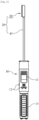
- FIG. 2 is a front view illustrating a breathalyzer according to an embodiment of the present disclosure
- FIG. 3 is a side view illustrating the breathalyzer illustrated in FIG. 2
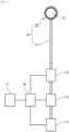
- FIG. 4 is a conceptual view schematically illustrating the breathalyzer illustrated in FIG. 2 .
- a breathalyzer includes a housing 10 and a loop-type sampling device 20.
- a display portion 11 is mounted on a front surface of an upper portion of the housing 10, and operation buttons 12 are mounted below the display portion 11 and on a side surface of the housing 10.
- a handle 13 is mounted on a lower portion of the housing 10.
- the loop-type sampling device 20 mounted on the upper portion of the housing 10 so that the loop-type sampling device 20 is capable of being easily replaced.
- the display portion 11 of the housing 10 is disposed such that an exhalation blown by a subject does not face a measurer who is looking at the display portion 11. That is, the display portion 11 is disposed such that a direction (a direction perpendicular to the ground in FIG. 3 ) that a loop-shaped body 30 faces is at a 90 degree angles with a direction that the display portion 11 faces (a right direction in FIG. 3 ) .
- the breathalyzer further includes a carbon dioxide sensor 50, an alcohol sensor 52, a suction pump 54, and a controller 56 that are mounted inside the housing 10.
- the carbon dioxide sensor 50 is configured to generate an electrical signal according to a carbon dioxide concentration of a sample gas that is collected through the loop-type sampling device 20.
- a conventional infrared-type gas sensor and so on may be used as the carbon dioxide sensor 50.
- the alcohol sensor 52 is configured to generate an electrical signal according to an alcohol concentration of the sample gas passing through the carbon dioxide sensor 50.
- a conventional semiconductor-type gas sensor, an electrochemical-type gas sensor, and so on may be used as the alcohol sensor 52.
- the suction pump 54 serves to introduce the sample gas into inner portions of the carbon dioxide sensor 50 and the alcohol sensor 52 when the suction pump 54 is operated.
- a diaphragm pump or a solenoid pump may be used as the suction pump 54.
- an upstream side and a downstream side is defined on the basis of a direction where the sample gas flows when the suction pump 54 is operated.
- the carbon dioxide sensor 50, the alcohol sensor 52, and the suction pump 54 are sequentially disposed, but the suction pump 54 may be disposed at an upstream side of the alcohol sensor 52.
- the controller 56 serves to control the carbon dioxide sensor 50, the alcohol sensor 52, and the suction pump 54.
- the controller 56 is also configured such that the controller 56 receives the electrical signal from the carbon dioxide sensor 50 and calculates the carbon dioxide concentration, and receives the electrical signal from the alcohol sensor 52, calculates the alcohol concentration, and transmits a result to the display portion 11.
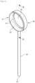
- FIG. 5 is a loop-type sampling device illustrated in FIG. 2
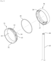
- FIG. 6 is an exploded perspective view illustrating the loop-type sampling device illustrated in FIG. 5
- FIG. 7 is a cross-sectional view of the loop-type sampling device illustrated in FIG. 5 taken along line A-A.
- the loop-type sampling device 20 includes the loop-shaped body 30, and includes a sample gas inlet tube 45 having a first end 46 connected to the body 30 and having a second end 47 coupled to the housing 10.
- the body 30 is formed in a loop shape forming a central opening 35 through which air containing an exhalation of a subject such as air around a driver seat of a vehicle passes or an exhalation blown by the subject passes.
- An entrance 41 where a part of a gas that passes through the central opening 35 is introduced is formed on the central opening 35 of the body 30.
- an inner passage 42 through which the sample gas that is a gas introduced through the entrance 41 is formed.
- the inner passage 42 is formed in an annular loop shape.
- the body 30 includes a first body 31 and a second body 36 that are generally formed in annular shapes.
- the first body 31 includes a guide surface 32 formed on the central opening 35, a first coupling surface 33 formed on an opposite side of the guide surface 32, and a protrusion surface 34 which extends from the first coupling surface 33 and which forms a protrusion portion 43 together with the guide surface 32.
- At least a portion of the guide surface 32 is inclined so as to guide a gas to the entrance 41.
- a concave portion and a convex portion are formed on the first coupling surface 33.
- the second body 36 includes a second coupling surface 37 coupled to the first coupling surface 33, and includes a curved surface 38 which extends from the second coupling surface 37 and which surrounds the protrusion portion 43 of the first body 31.
- a concave portion and a convex portion that are corresponding to the concave portion and the convex portion of the first coupling surface 33 are formed on the second coupling surface 37.
- the entrance 41 is formed between an end of the guide surface 32 and an end of the curved surface 38.
- the inner passage 42 is formed between the protrusion surface 34 and the curved surface 38.
- the sample gas inlet tube 45 serves to transmit the sample gas flowing through the inner passage 42 to the carbon dioxide sensor 50.
- a first end of the sample gas inlet tube 45 is in communication with the inner passage 42 of the body 30 from a lower end portion of the body 30, and a second end of the sample gas inlet tube 45 is fitted to the housing 10.
- a sealing member 39 is mounted between the first coupling surface 33 and the second coupling surface 37, thereby serving to prevent the sample gas that flows into the inner passage 42 from leaking to a gap between the first coupling surface 33 and the second coupling surface 37.
- the sealing member 39 may be an O-ring formed of a material having an elasticity.
- the sealing member 39 may be fitted to a recessed groove formed in the first coupling surface 33 and/or the second coupling surface 37.
- the body 30 of the loop-type sampling device 20 is disposed around the subject, and then the breathalyzer is operated by using the operation buttons 12 of the housing 10. Then, a warm-up of the carbon dioxide sensor 50 is started, and the suction pump 54 is operated.
- the suction pump 54 When the suction pump 54 is operated, a pressure inside the sample gas inlet tube 45 is lowered, and air around the subject is introduced into the inner passage 42 through the entrance 41 of the loop-type sampling device 20. After the introduced sample gas passes through the sample gas inlet tube 45, the introduced sample gas is introduced into the inner portion of the carbon dioxide sensor 50. In the carbon dioxide sensor 50, an electrical signal according to a carbon dioxide concentration of the sample gas is generated. This electrical signal is transmitted to the controller 56 of the breathalyzer, and the controller 56 calculates the carbon dioxide concentration on the basis of the electrical signal.
- the alcohol sensor 52 When the calculated carbon dioxide concentration is equal to or more than a reference value that is a 2000 ppm as an example, and when it is confirmed that a driver does not perform an evasive action such as ventilating an inside of the vehicle or minimizing breathing before a measurement, the alcohol sensor 52 generates the electrical signal according to the alcohol concentration of the introduced sample gas.
- a sensitivity of the alcohol sensor 52 may be increased by operating a solenoid pump two or more times.
- This electrical signal is transmitted to the controller 56, and the controller 56 measure the alcohol concentration on the basis of the electrical signal. Then, when the alcohol concentration is equal to or more than a predetermined value that is 3 ppm as an example, the controller 56 determines that the subject is inebriated, and the controller 56 sends a message through the display portion 11 to the measurer.
- the subject When the calculated carbon dioxide concentration is less than the reference value or the subject does not agree with a test result, the subject directly blows an exhalation to the body 30 of the loop-type sampling device 20, and the alcohol concentration may be measured again.
Landscapes
- Health & Medical Sciences (AREA)
- Life Sciences & Earth Sciences (AREA)
- Engineering & Computer Science (AREA)
- Biomedical Technology (AREA)
- Molecular Biology (AREA)
- Physics & Mathematics (AREA)
- General Health & Medical Sciences (AREA)
- Pathology (AREA)
- Biophysics (AREA)
- Animal Behavior & Ethology (AREA)
- Medical Informatics (AREA)
- Heart & Thoracic Surgery (AREA)
- Surgery (AREA)
- Public Health (AREA)
- Veterinary Medicine (AREA)
- Chemical & Material Sciences (AREA)
- Biochemistry (AREA)
- Immunology (AREA)
- General Physics & Mathematics (AREA)
- Physiology (AREA)
- Pulmonology (AREA)
- Analytical Chemistry (AREA)
- Hematology (AREA)
- Urology & Nephrology (AREA)
- Food Science & Technology (AREA)
- Medicinal Chemistry (AREA)
- Bioinformatics & Cheminformatics (AREA)
- Pharmacology & Pharmacy (AREA)
- Toxicology (AREA)
- Investigating Or Analysing Biological Materials (AREA)
- Sampling And Sample Adjustment (AREA)
Description
- The present disclosure relates to a loop-type sampling device and a breathalyzer including the same. More particularly, the present disclosure relates to a loop-type sampling device and a breathalyzer including the loop-type sampling device that is capable of minimizing an infection caused by droplets included in an exhalation (exhaled gas) of a subject.
- A breathalyzer measures a concentration of alcohol that is exhaled together with an exhalation of a subject. Since the concentration of alcohol discharged together with the exhalation is proportional to a concentration of alcohol in blood, a blood alcohol concentration (BAC) is capable of being calculated when the concentration of alcohol contained in the exhalation is measured.
- As illustrated in
FIG. 1 , in a conventional breathalyzer, anexhalation passage 2 formed in a cylindrical shape and coupled to a blowing tube 1 is used as a sampling device for collecting a part of the exhalation. Theexhalation passage 2 has both ends that are open. The blowing tube 1 may be coupled to an inlet port of a first end of theexhalation passage 2. The exhalation introduced into theexhalation passage 2 through the blowing tube 1 is discharged to the outside through a discharge port of a second end of theexhalation passage 2. Acollection hole 3 for supplying the part of the exhalation introduced into theexhalation passage 2 to analcohol sensor 5 is formed in theexhalation passage 2. Most of the exhalation introduced into theexhalation passage 2 is directly discharged to the outside through the discharge port, and a part of the exhalation is supplied to thealcohol sensor 5 through thecollection hole 3. Asuction pump 4 for introducing a sample gas to thealcohol sensor 5 is mounted on a rear end of thealcohol sensor 5. - However, it is known that droplets are mixed in the exhalation and viruses do not die in the droplets within 3 to 24 hours. Therefore, in a breathalyzer that is used by multiple subjects, another subject may be infected by droplets remaining in a sampling device of the breathalyzer. In addition, when an exhalation is blown, droplets discharged through the discharge port may splay on a measurer's face. In this manner, the conventional breathalyzer has a problem that there is a high risk of occurrence of a droplet infection between a subject and a measurer due to a structure of the sampling device of the conventional breathalyzer.
-
Document EP 3 059 572 A1 concerns gas sampling means for use with a gas sampling system. The gas sampling means include at least one length of tube and means to connect at least a first end of said tube to a central unit of a gas sampling system and/or a vacuum. At least part of the tube is formed from a porous material. The porous material is provided with a substantially even draw / suction / vacuum and/or the like through pores of the said porous material along substantially the length of the same. - Document
KR 101 873 642 B1 -
-
Korean Patent Application Publication No. 10-2017-0040890 -
Korean Patent No. 10-1525204 -
Korean Patent Application Publication No. 10-2016-0096251 -
Korean Patent No. 10-0706040 - Accordingly, the present disclosure has been made keeping in mind the above problems occurring in the related art, and an objective of the present disclosure is to provide a loop-type sampling device capable of minimizing a droplet infection.
- In addition, another objective of the present disclosure is to provide a breathalyzer capable of minimizing a droplet infection.
- The invention is set out in the appended set of claims.
- In order to achieve the objectives, according to the present disclosure, there is provided a loop-type sampling device including: a body formed in a loop shape forming a central opening through which a gas passes, the body having an entrance into which a part of the gas that passes through the central opening is introduced, and the body having an inner passage which is formed in a loop shape and into which a sample gas that is the gas passing through the entrance flows; and a sample gas inlet tube having a first end that is in communication with the inner passage, the sample gas inlet tube having a second end connected to a sample gas analysis device that is provided with a negative pressure providing means capable of suctioning the sample gas that flows into the inner passage.
- In addition, the body includes: a first body having a guide surface which is formed on the central opening and which has at least of a portion inclined so as to guide the gas to the entrance, the first body having a first coupling surface formed on an opposite side of the guide surface, and the first body having a protrusion surface which extends from the first coupling surface and which forms a protrusion portion together with the guide surface; and a second body having a second coupling surface coupled to the first coupling surface of the first body, the second body having a curved surface which extends from the second coupling surface and which surrounds the protrusion portion of the first body, and the entrance may be formed between an end of the guide surface and an end of the curved surface, and the inner passage may be formed between the protrusion surface and the curved surface.
- In addition, a sealing member may be mounted between the first coupling surface and the second coupling surface.
- In addition, a concave portion and a convex portion that are engaged with each other may be formed on the first coupling surface and the second coupling surface.
- In addition, a breathalyzer may include: the loop-type sampling device; a carbon dioxide sensor configured to generate an electrical signal according to a carbon dioxide concentration of a sample gas introduced through the sample gas inlet tube; an alcohol sensor configured to generate an electrical signal according to an alcohol concentration of the sample gas introduced through the sample gas inlet tube; and a controller configured to determine an inebriation state on the basis of the electrical signal of the alcohol sensor when the carbon dioxide concentration according to the electrical signal of the carbon dioxide sensor is equal to or more than a predetermined value, wherein the negative pressure providing means may be a suction pump connected to a downstream side of the sample gas inlet tube.
- The loop-type sampling device and the breathalyzer of the present disclosure have an advantage that a droplet infection between a subject and a measurer is capable of being minimized.
- In the loop-type sampling device according to the present disclosure, since an exhalation is easy to pass through without hitting the loop-type sampling device and the loop-type sampling device has a structure lowering a possibility of remaining droplets, a possibility of occurrence of a droplet infection between a subject and a measurer during a inebriation testing process is lowered when the loop-type sampling device according to the present disclosure is used.
- In addition, in the loop-type sampling device according to the present disclosure, since a distance between a subject and a measurer is capable of being increased by extending a length of the sample gas inlet tube, so that a possibility of occurrence of a droplet infection of the measurer caused by droplets contained in the exhalation of the infected subject is lowered.
-
-
FIG. 1 is a conceptual view schematically illustrating a conventional breathalyzer. -
FIG. 2 is a front view illustrating a breathalyzer according to an embodiment of the present disclosure. -
FIG. 3 is a side view illustrating the breathalyzer illustrated inFIG. 2 . -
FIG. 4 is a conceptual view schematically illustrating the breathalyzer illustrated inFIG. 2 . -
FIG. 5 is a loop-type sampling device illustrated inFIG. 2 . -
FIG. 6 is an exploded perspective view illustrating the loop-type sampling device illustrated inFIG. 5 . -
FIG. 7 is a cross-sectional view of the loop-type sampling device illustrated inFIG. 5 taken along line A-A. - Hereinafter, an embodiment of the present disclosure will be described in detail with reference to accompanying drawings. The following embodiment is provided by way of example so as to fully convey the spirit of the present disclosure to those skilled in the art. Accordingly, the present disclosure is not limited to the embodiment disclosed herein and can also be implemented in different forms. In addition, the drawings may be exaggerated in width, length, and thickness of components for descriptive convenience and clarity only. Like components will be denoted by like reference numerals throughout the specification.
-
FIG. 2 is a front view illustrating a breathalyzer according to an embodiment of the present disclosure,FIG. 3 is a side view illustrating the breathalyzer illustrated inFIG. 2 , andFIG. 4 is a conceptual view schematically illustrating the breathalyzer illustrated inFIG. 2 . - As illustrated in
FIGS. 2 and3 , a breathalyzer according to an embodiment of the present disclosure includes ahousing 10 and a loop-type sampling device 20. - A
display portion 11 is mounted on a front surface of an upper portion of thehousing 10, andoperation buttons 12 are mounted below thedisplay portion 11 and on a side surface of thehousing 10. Ahandle 13 is mounted on a lower portion of thehousing 10. The loop-type sampling device 20 mounted on the upper portion of thehousing 10 so that the loop-type sampling device 20 is capable of being easily replaced. Thedisplay portion 11 of thehousing 10 is disposed such that an exhalation blown by a subject does not face a measurer who is looking at thedisplay portion 11. That is, thedisplay portion 11 is disposed such that a direction (a direction perpendicular to the ground inFIG. 3 ) that a loop-shaped body 30 faces is at a 90 degree angles with a direction that thedisplay portion 11 faces (a right direction inFIG. 3 ) . - In addition, as illustrated in
FIG. 4 , the breathalyzer further includes acarbon dioxide sensor 50, analcohol sensor 52, asuction pump 54, and acontroller 56 that are mounted inside thehousing 10. - The
carbon dioxide sensor 50 is configured to generate an electrical signal according to a carbon dioxide concentration of a sample gas that is collected through the loop-type sampling device 20. A conventional infrared-type gas sensor and so on may be used as thecarbon dioxide sensor 50. - The
alcohol sensor 52 is configured to generate an electrical signal according to an alcohol concentration of the sample gas passing through thecarbon dioxide sensor 50. A conventional semiconductor-type gas sensor, an electrochemical-type gas sensor, and so on may be used as thealcohol sensor 52. - The
suction pump 54 serves to introduce the sample gas into inner portions of thecarbon dioxide sensor 50 and thealcohol sensor 52 when thesuction pump 54 is operated. A diaphragm pump or a solenoid pump may be used as thesuction pump 54. In the present disclosure, an upstream side and a downstream side is defined on the basis of a direction where the sample gas flows when thesuction pump 54 is operated. - In the embodiment illustrated in
FIG. 4 , an arrangement order is illustrated that thecarbon dioxide sensor 50, thealcohol sensor 52, and thesuction pump 54 are sequentially disposed, but thesuction pump 54 may be disposed at an upstream side of thealcohol sensor 52. - The
controller 56 serves to control thecarbon dioxide sensor 50, thealcohol sensor 52, and thesuction pump 54. In addition, thecontroller 56 is also configured such that thecontroller 56 receives the electrical signal from thecarbon dioxide sensor 50 and calculates the carbon dioxide concentration, and receives the electrical signal from thealcohol sensor 52, calculates the alcohol concentration, and transmits a result to thedisplay portion 11. -
FIG. 5 is a loop-type sampling device illustrated inFIG. 2 ,FIG. 6 is an exploded perspective view illustrating the loop-type sampling device illustrated inFIG. 5 , andFIG. 7 is a cross-sectional view of the loop-type sampling device illustrated inFIG. 5 taken along line A-A. - As illustrated in
FIGS. 5 to 7 , the loop-type sampling device 20 includes the loop-shapedbody 30, and includes a samplegas inlet tube 45 having afirst end 46 connected to thebody 30 and having asecond end 47 coupled to thehousing 10. - The
body 30 is formed in a loop shape forming acentral opening 35 through which air containing an exhalation of a subject such as air around a driver seat of a vehicle passes or an exhalation blown by the subject passes. Anentrance 41 where a part of a gas that passes through thecentral opening 35 is introduced is formed on thecentral opening 35 of thebody 30. In addition, aninner passage 42 through which the sample gas that is a gas introduced through theentrance 41 is formed. Theinner passage 42 is formed in an annular loop shape. - The
body 30 includes afirst body 31 and asecond body 36 that are generally formed in annular shapes. Thefirst body 31 includes aguide surface 32 formed on thecentral opening 35, afirst coupling surface 33 formed on an opposite side of theguide surface 32, and aprotrusion surface 34 which extends from thefirst coupling surface 33 and which forms aprotrusion portion 43 together with theguide surface 32. At least a portion of theguide surface 32 is inclined so as to guide a gas to theentrance 41. A concave portion and a convex portion are formed on thefirst coupling surface 33. - The
second body 36 includes asecond coupling surface 37 coupled to thefirst coupling surface 33, and includes acurved surface 38 which extends from thesecond coupling surface 37 and which surrounds theprotrusion portion 43 of thefirst body 31. A concave portion and a convex portion that are corresponding to the concave portion and the convex portion of thefirst coupling surface 33 are formed on thesecond coupling surface 37. - When the
first body 31 and thesecond body 36 having the shapes as described above are assembled such that thefirst coupling surface 33 is in contact with thesecond coupling surface 37, theentrance 41 is formed between an end of theguide surface 32 and an end of thecurved surface 38. In addition, theinner passage 42 is formed between theprotrusion surface 34 and thecurved surface 38. - The sample
gas inlet tube 45 serves to transmit the sample gas flowing through theinner passage 42 to thecarbon dioxide sensor 50. A first end of the samplegas inlet tube 45 is in communication with theinner passage 42 of thebody 30 from a lower end portion of thebody 30, and a second end of the samplegas inlet tube 45 is fitted to thehousing 10. - A sealing
member 39 is mounted between thefirst coupling surface 33 and thesecond coupling surface 37, thereby serving to prevent the sample gas that flows into theinner passage 42 from leaking to a gap between thefirst coupling surface 33 and thesecond coupling surface 37. The sealingmember 39 may be an O-ring formed of a material having an elasticity. The sealingmember 39 may be fitted to a recessed groove formed in thefirst coupling surface 33 and/or thesecond coupling surface 37. - Hereinafter, an operation of the breathalyzer according to an embodiment of the present disclosure will be described.
- By using a window at the driver seat on which the subject is seated, the
body 30 of the loop-type sampling device 20 is disposed around the subject, and then the breathalyzer is operated by using theoperation buttons 12 of thehousing 10. Then, a warm-up of thecarbon dioxide sensor 50 is started, and thesuction pump 54 is operated. - When the
suction pump 54 is operated, a pressure inside the samplegas inlet tube 45 is lowered, and air around the subject is introduced into theinner passage 42 through theentrance 41 of the loop-type sampling device 20. After the introduced sample gas passes through the samplegas inlet tube 45, the introduced sample gas is introduced into the inner portion of thecarbon dioxide sensor 50. In thecarbon dioxide sensor 50, an electrical signal according to a carbon dioxide concentration of the sample gas is generated. This electrical signal is transmitted to thecontroller 56 of the breathalyzer, and thecontroller 56 calculates the carbon dioxide concentration on the basis of the electrical signal. - When the calculated carbon dioxide concentration is equal to or more than a reference value that is a 2000 ppm as an example, and when it is confirmed that a driver does not perform an evasive action such as ventilating an inside of the vehicle or minimizing breathing before a measurement, the
alcohol sensor 52 generates the electrical signal according to the alcohol concentration of the introduced sample gas. When an electrochemical-type gas sensor is used as thealcohol sensor 52, a sensitivity of thealcohol sensor 52 may be increased by operating a solenoid pump two or more times. - This electrical signal is transmitted to the
controller 56, and thecontroller 56 measure the alcohol concentration on the basis of the electrical signal. Then, when the alcohol concentration is equal to or more than a predetermined value that is 3 ppm as an example, thecontroller 56 determines that the subject is inebriated, and thecontroller 56 sends a message through thedisplay portion 11 to the measurer. - When the calculated carbon dioxide concentration is less than the reference value or the subject does not agree with a test result, the subject directly blows an exhalation to the
body 30 of the loop-type sampling device 20, and the alcohol concentration may be measured again. -
- 10:
- housing
- 11:
- display portion
- 12:
- operation button
- 13:
- handle
- 20:
- loop-type sampling device
- 30:
- body
- 31
- first body
- 32:
- guide surface
- 33:
- first coupling surface
- 34:
- protrusion surface
- 35:
- central opening
- 36:
- second body
- 37:
- second coupling surface
- 38:
- curved surface
- 39:
- sealing member
- 41:
- entrance
- 42:
- inner passage
- 45:
- sample gas inlet tube
-
- 50:
- carbon dioxide sensor
- 52
- alcohol sensor
- 54:
- suction pump
- 56:
- controller
Claims (4)
- A loop-type exhalation sampling device (20) comprising:a body (30) formed in a loop shape forming a central opening (35) configured so that a gas can pass through, the body (30) having an entrance (41) configured so that a part of the gas that passes through the central opening (35) is introduced into the entrance (41), and the body (30) having an inner passage (42) which is formed in a loop shape and is configured so that a sample gas that is the gas passing through the entrance (41) flows into the inner passage (42); anda sample gas inlet tube (45) having a first end that is in communication with the inner passage (42), the sample gas inlet tube (45) having a second end connected to a sample gas analysis device that is provided with a negative pressure providing means capable of suctioning the sample gas that flows into the inner passage (42),whereinthe body (30) comprises:a first body (31) having a guide surface (32) which is formed on the central opening (35) and which has at least of a portion inclined so as to guide the gas to the entrance (41), the first body (31) having a first coupling surface (33) formed on an opposite side of the guide surface (32), and the first body (31) having a protrusion surface (34) which extends from the first coupling surface (33) and which forms a protrusion portion together with the guide surface (32); anda second body (36) having a second coupling surface (37) coupled to the first coupling surface (33) of the first body (31), the second body (36) having a curved surface (38) which extends from the second coupling surface (37) and which surrounds the protrusion portion of the first body (31), andthe entrance (41) is formed between an end of the guide surface (32) and an end of the curved surface (38), and the inner passage (42) is formed between the protrusion surface (34) and the curved surface (38).
- The loop-type exhalation sampling device (20) of claim 1, wherein a sealing member (39) is mounted between the first coupling surface (33) and the second coupling surface (37).
- The loop-type exhalation sampling device (20) of claim 1, wherein a concave portion and a convex portion that are engaged with each other are formed on the first coupling surface (33) and the second coupling surface (37).
- A breathalyzer comprising:the loop-type exhalation sampling device (20) of any one of claims 1 to 3;a carbon dioxide sensor (50) configured to generate an electrical signal according to a carbon dioxide concentration of a sample gas introduced through the sample gas inlet tube (45) ;an alcohol sensor (52) configured to generate an electrical signal according to an alcohol concentration of the sample gas introduced through the sample gas inlet tube (45); anda controller (56) configured to determine an inebriation state on the basis of the electrical signal of the alcohol sensor when the carbon dioxide concentration according to the electrical signal of the carbon dioxide sensor (50) is equal to or more than a predetermined value,wherein the negative pressure providing means is a suction pump connected to a downstream side of the sample gas inlet tube (45).
Applications Claiming Priority (2)
| Application Number | Priority Date | Filing Date | Title |
|---|---|---|---|
| KR1020200050260A KR102290066B1 (en) | 2020-04-24 | 2020-04-24 | Loop-type sampling device and breath alcohol analyzer with the same |
| PCT/KR2021/004388 WO2021215711A1 (en) | 2020-04-24 | 2021-04-08 | Loop-type sampling device and breathalyzer comprising same |
Publications (3)
| Publication Number | Publication Date |
|---|---|
| EP4140405A1 EP4140405A1 (en) | 2023-03-01 |
| EP4140405A4 EP4140405A4 (en) | 2023-08-23 |
| EP4140405B1 true EP4140405B1 (en) | 2024-06-05 |
Family
ID=77464426
Family Applications (1)
| Application Number | Title | Priority Date | Filing Date |
|---|---|---|---|
| EP21791822.6A Active EP4140405B1 (en) | 2020-04-24 | 2021-04-08 | Loop-type sampling device and breathalyzer comprising same |
Country Status (3)
| Country | Link |
|---|---|
| EP (1) | EP4140405B1 (en) |
| KR (1) | KR102290066B1 (en) |
| WO (1) | WO2021215711A1 (en) |
Family Cites Families (10)
| Publication number | Priority date | Publication date | Assignee | Title |
|---|---|---|---|---|
| US6463814B1 (en) * | 1999-11-05 | 2002-10-15 | Graftech | Bioaerosol slit impaction sampling device |
| WO2005028788A1 (en) | 2003-09-17 | 2005-03-31 | Hiroshi Kamiki | Key for vehicle |
| EP2395915B1 (en) * | 2009-02-10 | 2019-01-16 | Hok Instrument AB | Breath analysis |
| KR101525204B1 (en) | 2014-01-21 | 2015-06-10 | 자동차부품연구원 | Drunk driving prevention apparatus and method |
| KR20160096251A (en) | 2015-02-04 | 2016-08-16 | 강릉원주대학교산학협력단 | Drunk Driving Prevention Device |
| GB201502714D0 (en) * | 2015-02-18 | 2015-04-01 | Gds Technologies Ltd | Sampling apparatus and method of use thereof |
| KR101800508B1 (en) | 2015-10-06 | 2017-12-20 | 엘지전자 주식회사 | Method for preventing drunk-driving and driver assistance appratus having the same |
| KR101873642B1 (en) * | 2016-08-18 | 2018-07-04 | (주)센텍코리아 | Multi-gas sensor |
| CN107894606B (en) * | 2017-11-20 | 2019-07-02 | 浙江大学 | Carbon-14 test bottle, test device and method, sampling system and calculation method |
| KR101998612B1 (en) * | 2018-01-19 | 2019-07-11 | (주)센텍코리아 | Device for preventing drunk driving |
-
2020
- 2020-04-24 KR KR1020200050260A patent/KR102290066B1/en active Active
-
2021
- 2021-04-08 EP EP21791822.6A patent/EP4140405B1/en active Active
- 2021-04-08 WO PCT/KR2021/004388 patent/WO2021215711A1/en not_active Ceased
Also Published As
| Publication number | Publication date |
|---|---|
| WO2021215711A1 (en) | 2021-10-28 |
| KR102290066B1 (en) | 2021-08-18 |
| EP4140405A4 (en) | 2023-08-23 |
| EP4140405A1 (en) | 2023-03-01 |
Similar Documents
| Publication | Publication Date | Title |
|---|---|---|
| EP2233167B1 (en) | Arrangement for improving accuracy of pressure measurement and flow sensor | |
| US5676132A (en) | Pulmonary interface system | |
| US5739412A (en) | Gas sampling system having a mouthpiece | |
| US7748280B2 (en) | Sidestream gas sampling system with closed sample circuit | |
| CA1195204A (en) | Inhalation valve | |
| US6896713B1 (en) | Liquid separator with holder unit | |
| EP2395915B1 (en) | Breath analysis | |
| US6044843A (en) | Moisture resistant airway adapter for monitoring constituent gases | |
| US10136839B2 (en) | Airway adaptor | |
| GB2271635A (en) | Sampling/analysing gas or liquid taken from a patient | |
| CA2501641C (en) | Integrated sample cell and filter and system using same | |
| EP0242790B1 (en) | Liquid trap for medical application | |
| EP4140405A1 (en) | Loop-type sampling device and breathalyzer comprising same | |
| JP3882612B2 (en) | Infrared gas analyzer | |
| EP1420842B1 (en) | Device for quantitative analysis of respiratory gases | |
| CN113768492A (en) | End-expiratory gas acquisition device and method for separating airway | |
| AU761894B2 (en) | Pulmonary interface system | |
| GB2300261A (en) | Sampling and analysing samples from a patient | |
| US20250344964A1 (en) | Pulmonary disease screening system and method for screening pulmonary diseases using same | |
| JPH0829301A (en) | Exhalation sampling device | |
| AU1086097A (en) | Pulmonary interface system | |
| JPH0733986B2 (en) | Blood biochemical substance continuous measuring device |
Legal Events
| Date | Code | Title | Description |
|---|---|---|---|
| STAA | Information on the status of an ep patent application or granted ep patent |
Free format text: STATUS: THE INTERNATIONAL PUBLICATION HAS BEEN MADE |
|
| PUAI | Public reference made under article 153(3) epc to a published international application that has entered the european phase |
Free format text: ORIGINAL CODE: 0009012 |
|
| STAA | Information on the status of an ep patent application or granted ep patent |
Free format text: STATUS: REQUEST FOR EXAMINATION WAS MADE |
|
| 17P | Request for examination filed |
Effective date: 20221121 |
|
| AK | Designated contracting states |
Kind code of ref document: A1 Designated state(s): AL AT BE BG CH CY CZ DE DK EE ES FI FR GB GR HR HU IE IS IT LI LT LU LV MC MK MT NL NO PL PT RO RS SE SI SK SM TR |
|
| DAV | Request for validation of the european patent (deleted) | ||
| DAX | Request for extension of the european patent (deleted) | ||
| A4 | Supplementary search report drawn up and despatched |
Effective date: 20230721 |
|
| RIC1 | Information provided on ipc code assigned before grant |
Ipc: G01N 1/22 20060101ALI20230717BHEP Ipc: G01N 33/497 20060101ALI20230717BHEP Ipc: G01N 1/24 20060101ALI20230717BHEP Ipc: A61B 10/00 20060101ALI20230717BHEP Ipc: A61B 5/00 20060101ALI20230717BHEP Ipc: A61B 5/08 20060101ALI20230717BHEP Ipc: A61B 5/097 20060101AFI20230717BHEP |
|
| GRAP | Despatch of communication of intention to grant a patent |
Free format text: ORIGINAL CODE: EPIDOSNIGR1 |
|
| STAA | Information on the status of an ep patent application or granted ep patent |
Free format text: STATUS: GRANT OF PATENT IS INTENDED |
|
| RIC1 | Information provided on ipc code assigned before grant |
Ipc: G01N 1/22 20060101ALI20240207BHEP Ipc: G01N 33/497 20060101ALI20240207BHEP Ipc: G01N 1/24 20060101ALI20240207BHEP Ipc: A61B 10/00 20060101ALI20240207BHEP Ipc: A61B 5/00 20060101ALI20240207BHEP Ipc: A61B 5/08 20060101ALI20240207BHEP Ipc: A61B 5/097 20060101AFI20240207BHEP |
|
| INTG | Intention to grant announced |
Effective date: 20240228 |
|
| GRAS | Grant fee paid |
Free format text: ORIGINAL CODE: EPIDOSNIGR3 |
|
| GRAA | (expected) grant |
Free format text: ORIGINAL CODE: 0009210 |
|
| STAA | Information on the status of an ep patent application or granted ep patent |
Free format text: STATUS: THE PATENT HAS BEEN GRANTED |
|
| AK | Designated contracting states |
Kind code of ref document: B1 Designated state(s): AL AT BE BG CH CY CZ DE DK EE ES FI FR GB GR HR HU IE IS IT LI LT LU LV MC MK MT NL NO PL PT RO RS SE SI SK SM TR |
|
| REG | Reference to a national code |
Ref country code: CH Ref legal event code: EP |
|
| REG | Reference to a national code |
Ref country code: DE Ref legal event code: R096 Ref document number: 602021014164 Country of ref document: DE |
|
| REG | Reference to a national code |
Ref country code: IE Ref legal event code: FG4D |
|
| REG | Reference to a national code |
Ref country code: SE Ref legal event code: TRGR |
|
| REG | Reference to a national code |
Ref country code: LT Ref legal event code: MG9D |
|
| PG25 | Lapsed in a contracting state [announced via postgrant information from national office to epo] |
Ref country code: BG Free format text: LAPSE BECAUSE OF FAILURE TO SUBMIT A TRANSLATION OF THE DESCRIPTION OR TO PAY THE FEE WITHIN THE PRESCRIBED TIME-LIMIT Effective date: 20240605 |
|
| REG | Reference to a national code |
Ref country code: NL Ref legal event code: MP Effective date: 20240605 |
|
| PG25 | Lapsed in a contracting state [announced via postgrant information from national office to epo] |
Ref country code: HR Free format text: LAPSE BECAUSE OF FAILURE TO SUBMIT A TRANSLATION OF THE DESCRIPTION OR TO PAY THE FEE WITHIN THE PRESCRIBED TIME-LIMIT Effective date: 20240605 Ref country code: FI Free format text: LAPSE BECAUSE OF FAILURE TO SUBMIT A TRANSLATION OF THE DESCRIPTION OR TO PAY THE FEE WITHIN THE PRESCRIBED TIME-LIMIT Effective date: 20240605 |
|
| PG25 | Lapsed in a contracting state [announced via postgrant information from national office to epo] |
Ref country code: GR Free format text: LAPSE BECAUSE OF FAILURE TO SUBMIT A TRANSLATION OF THE DESCRIPTION OR TO PAY THE FEE WITHIN THE PRESCRIBED TIME-LIMIT Effective date: 20240906 |
|
| PG25 | Lapsed in a contracting state [announced via postgrant information from national office to epo] |
Ref country code: ES Free format text: LAPSE BECAUSE OF FAILURE TO SUBMIT A TRANSLATION OF THE DESCRIPTION OR TO PAY THE FEE WITHIN THE PRESCRIBED TIME-LIMIT Effective date: 20240605 |
|
| PG25 | Lapsed in a contracting state [announced via postgrant information from national office to epo] |
Ref country code: LV Free format text: LAPSE BECAUSE OF FAILURE TO SUBMIT A TRANSLATION OF THE DESCRIPTION OR TO PAY THE FEE WITHIN THE PRESCRIBED TIME-LIMIT Effective date: 20240605 |
|
| PG25 | Lapsed in a contracting state [announced via postgrant information from national office to epo] |
Ref country code: NO Free format text: LAPSE BECAUSE OF FAILURE TO SUBMIT A TRANSLATION OF THE DESCRIPTION OR TO PAY THE FEE WITHIN THE PRESCRIBED TIME-LIMIT Effective date: 20240905 Ref country code: LV Free format text: LAPSE BECAUSE OF FAILURE TO SUBMIT A TRANSLATION OF THE DESCRIPTION OR TO PAY THE FEE WITHIN THE PRESCRIBED TIME-LIMIT Effective date: 20240605 Ref country code: HR Free format text: LAPSE BECAUSE OF FAILURE TO SUBMIT A TRANSLATION OF THE DESCRIPTION OR TO PAY THE FEE WITHIN THE PRESCRIBED TIME-LIMIT Effective date: 20240605 Ref country code: GR Free format text: LAPSE BECAUSE OF FAILURE TO SUBMIT A TRANSLATION OF THE DESCRIPTION OR TO PAY THE FEE WITHIN THE PRESCRIBED TIME-LIMIT Effective date: 20240906 Ref country code: FI Free format text: LAPSE BECAUSE OF FAILURE TO SUBMIT A TRANSLATION OF THE DESCRIPTION OR TO PAY THE FEE WITHIN THE PRESCRIBED TIME-LIMIT Effective date: 20240605 Ref country code: ES Free format text: LAPSE BECAUSE OF FAILURE TO SUBMIT A TRANSLATION OF THE DESCRIPTION OR TO PAY THE FEE WITHIN THE PRESCRIBED TIME-LIMIT Effective date: 20240605 Ref country code: BG Free format text: LAPSE BECAUSE OF FAILURE TO SUBMIT A TRANSLATION OF THE DESCRIPTION OR TO PAY THE FEE WITHIN THE PRESCRIBED TIME-LIMIT Effective date: 20240605 Ref country code: RS Free format text: LAPSE BECAUSE OF FAILURE TO SUBMIT A TRANSLATION OF THE DESCRIPTION OR TO PAY THE FEE WITHIN THE PRESCRIBED TIME-LIMIT Effective date: 20240905 |
|
| PG25 | Lapsed in a contracting state [announced via postgrant information from national office to epo] |
Ref country code: NL Free format text: LAPSE BECAUSE OF FAILURE TO SUBMIT A TRANSLATION OF THE DESCRIPTION OR TO PAY THE FEE WITHIN THE PRESCRIBED TIME-LIMIT Effective date: 20240605 |
|
| REG | Reference to a national code |
Ref country code: AT Ref legal event code: MK05 Ref document number: 1691822 Country of ref document: AT Kind code of ref document: T Effective date: 20240605 |
|
| PG25 | Lapsed in a contracting state [announced via postgrant information from national office to epo] |
Ref country code: NL Free format text: LAPSE BECAUSE OF FAILURE TO SUBMIT A TRANSLATION OF THE DESCRIPTION OR TO PAY THE FEE WITHIN THE PRESCRIBED TIME-LIMIT Effective date: 20240605 |
|
| PG25 | Lapsed in a contracting state [announced via postgrant information from national office to epo] |
Ref country code: PT Free format text: LAPSE BECAUSE OF FAILURE TO SUBMIT A TRANSLATION OF THE DESCRIPTION OR TO PAY THE FEE WITHIN THE PRESCRIBED TIME-LIMIT Effective date: 20241007 |
|
| PG25 | Lapsed in a contracting state [announced via postgrant information from national office to epo] |
Ref country code: PT Free format text: LAPSE BECAUSE OF FAILURE TO SUBMIT A TRANSLATION OF THE DESCRIPTION OR TO PAY THE FEE WITHIN THE PRESCRIBED TIME-LIMIT Effective date: 20241007 |
|
| PG25 | Lapsed in a contracting state [announced via postgrant information from national office to epo] |
Ref country code: PL Free format text: LAPSE BECAUSE OF FAILURE TO SUBMIT A TRANSLATION OF THE DESCRIPTION OR TO PAY THE FEE WITHIN THE PRESCRIBED TIME-LIMIT Effective date: 20240605 |
|
| PG25 | Lapsed in a contracting state [announced via postgrant information from national office to epo] |
Ref country code: EE Free format text: LAPSE BECAUSE OF FAILURE TO SUBMIT A TRANSLATION OF THE DESCRIPTION OR TO PAY THE FEE WITHIN THE PRESCRIBED TIME-LIMIT Effective date: 20240605 |
|
| PG25 | Lapsed in a contracting state [announced via postgrant information from national office to epo] |
Ref country code: IS Free format text: LAPSE BECAUSE OF FAILURE TO SUBMIT A TRANSLATION OF THE DESCRIPTION OR TO PAY THE FEE WITHIN THE PRESCRIBED TIME-LIMIT Effective date: 20241005 Ref country code: AT Free format text: LAPSE BECAUSE OF FAILURE TO SUBMIT A TRANSLATION OF THE DESCRIPTION OR TO PAY THE FEE WITHIN THE PRESCRIBED TIME-LIMIT Effective date: 20240605 |
|
| PG25 | Lapsed in a contracting state [announced via postgrant information from national office to epo] |
Ref country code: CZ Free format text: LAPSE BECAUSE OF FAILURE TO SUBMIT A TRANSLATION OF THE DESCRIPTION OR TO PAY THE FEE WITHIN THE PRESCRIBED TIME-LIMIT Effective date: 20240605 |
|
| PG25 | Lapsed in a contracting state [announced via postgrant information from national office to epo] |
Ref country code: RO Free format text: LAPSE BECAUSE OF FAILURE TO SUBMIT A TRANSLATION OF THE DESCRIPTION OR TO PAY THE FEE WITHIN THE PRESCRIBED TIME-LIMIT Effective date: 20240605 Ref country code: SK Free format text: LAPSE BECAUSE OF FAILURE TO SUBMIT A TRANSLATION OF THE DESCRIPTION OR TO PAY THE FEE WITHIN THE PRESCRIBED TIME-LIMIT Effective date: 20240605 |
|
| PG25 | Lapsed in a contracting state [announced via postgrant information from national office to epo] |
Ref country code: SM Free format text: LAPSE BECAUSE OF FAILURE TO SUBMIT A TRANSLATION OF THE DESCRIPTION OR TO PAY THE FEE WITHIN THE PRESCRIBED TIME-LIMIT Effective date: 20240605 |
|
| PG25 | Lapsed in a contracting state [announced via postgrant information from national office to epo] |
Ref country code: SM Free format text: LAPSE BECAUSE OF FAILURE TO SUBMIT A TRANSLATION OF THE DESCRIPTION OR TO PAY THE FEE WITHIN THE PRESCRIBED TIME-LIMIT Effective date: 20240605 Ref country code: SK Free format text: LAPSE BECAUSE OF FAILURE TO SUBMIT A TRANSLATION OF THE DESCRIPTION OR TO PAY THE FEE WITHIN THE PRESCRIBED TIME-LIMIT Effective date: 20240605 Ref country code: RO Free format text: LAPSE BECAUSE OF FAILURE TO SUBMIT A TRANSLATION OF THE DESCRIPTION OR TO PAY THE FEE WITHIN THE PRESCRIBED TIME-LIMIT Effective date: 20240605 Ref country code: PL Free format text: LAPSE BECAUSE OF FAILURE TO SUBMIT A TRANSLATION OF THE DESCRIPTION OR TO PAY THE FEE WITHIN THE PRESCRIBED TIME-LIMIT Effective date: 20240605 Ref country code: IS Free format text: LAPSE BECAUSE OF FAILURE TO SUBMIT A TRANSLATION OF THE DESCRIPTION OR TO PAY THE FEE WITHIN THE PRESCRIBED TIME-LIMIT Effective date: 20241005 Ref country code: EE Free format text: LAPSE BECAUSE OF FAILURE TO SUBMIT A TRANSLATION OF THE DESCRIPTION OR TO PAY THE FEE WITHIN THE PRESCRIBED TIME-LIMIT Effective date: 20240605 Ref country code: CZ Free format text: LAPSE BECAUSE OF FAILURE TO SUBMIT A TRANSLATION OF THE DESCRIPTION OR TO PAY THE FEE WITHIN THE PRESCRIBED TIME-LIMIT Effective date: 20240605 Ref country code: AT Free format text: LAPSE BECAUSE OF FAILURE TO SUBMIT A TRANSLATION OF THE DESCRIPTION OR TO PAY THE FEE WITHIN THE PRESCRIBED TIME-LIMIT Effective date: 20240605 |
|
| PG25 | Lapsed in a contracting state [announced via postgrant information from national office to epo] |
Ref country code: IT Free format text: LAPSE BECAUSE OF FAILURE TO SUBMIT A TRANSLATION OF THE DESCRIPTION OR TO PAY THE FEE WITHIN THE PRESCRIBED TIME-LIMIT Effective date: 20240605 |
|
| REG | Reference to a national code |
Ref country code: DE Ref legal event code: R097 Ref document number: 602021014164 Country of ref document: DE |
|
| PLBE | No opposition filed within time limit |
Free format text: ORIGINAL CODE: 0009261 |
|
| STAA | Information on the status of an ep patent application or granted ep patent |
Free format text: STATUS: NO OPPOSITION FILED WITHIN TIME LIMIT |
|
| PG25 | Lapsed in a contracting state [announced via postgrant information from national office to epo] |
Ref country code: DK Free format text: LAPSE BECAUSE OF FAILURE TO SUBMIT A TRANSLATION OF THE DESCRIPTION OR TO PAY THE FEE WITHIN THE PRESCRIBED TIME-LIMIT Effective date: 20240605 |
|
| 26N | No opposition filed |
Effective date: 20250306 |
|
| PGFP | Annual fee paid to national office [announced via postgrant information from national office to epo] |
Ref country code: DE Payment date: 20250424 Year of fee payment: 5 |
|
| PGFP | Annual fee paid to national office [announced via postgrant information from national office to epo] |
Ref country code: SE Payment date: 20250429 Year of fee payment: 5 |
|
| REG | Reference to a national code |
Ref country code: CH Ref legal event code: H13 Free format text: ST27 STATUS EVENT CODE: U-0-0-H10-H13 (AS PROVIDED BY THE NATIONAL OFFICE) Effective date: 20251125 |
|
| PG25 | Lapsed in a contracting state [announced via postgrant information from national office to epo] |
Ref country code: LU Free format text: LAPSE BECAUSE OF NON-PAYMENT OF DUE FEES Effective date: 20250408 |
|
| PG25 | Lapsed in a contracting state [announced via postgrant information from national office to epo] |
Ref country code: MC Free format text: LAPSE BECAUSE OF FAILURE TO SUBMIT A TRANSLATION OF THE DESCRIPTION OR TO PAY THE FEE WITHIN THE PRESCRIBED TIME-LIMIT Effective date: 20240605 |
|
| GBPC | Gb: european patent ceased through non-payment of renewal fee |
Effective date: 20250408 |
|
| REG | Reference to a national code |
Ref country code: BE Ref legal event code: MM Effective date: 20250430 |
|
| PG25 | Lapsed in a contracting state [announced via postgrant information from national office to epo] |
Ref country code: GB Free format text: LAPSE BECAUSE OF NON-PAYMENT OF DUE FEES Effective date: 20250408 |
|
| PG25 | Lapsed in a contracting state [announced via postgrant information from national office to epo] |
Ref country code: FR Free format text: LAPSE BECAUSE OF NON-PAYMENT OF DUE FEES Effective date: 20250430 |
|
| PG25 | Lapsed in a contracting state [announced via postgrant information from national office to epo] |
Ref country code: BE Free format text: LAPSE BECAUSE OF NON-PAYMENT OF DUE FEES Effective date: 20250430 |
|
| PG25 | Lapsed in a contracting state [announced via postgrant information from national office to epo] |
Ref country code: CH Free format text: LAPSE BECAUSE OF NON-PAYMENT OF DUE FEES Effective date: 20250430 |
|
| PG25 | Lapsed in a contracting state [announced via postgrant information from national office to epo] |
Ref country code: IE Free format text: LAPSE BECAUSE OF NON-PAYMENT OF DUE FEES Effective date: 20250408 |