EP4140358A1 - Structure of a brush for a sweeper machine - Google Patents
Structure of a brush for a sweeper machine Download PDFInfo
- Publication number
- EP4140358A1 EP4140358A1 EP21792823.3A EP21792823A EP4140358A1 EP 4140358 A1 EP4140358 A1 EP 4140358A1 EP 21792823 A EP21792823 A EP 21792823A EP 4140358 A1 EP4140358 A1 EP 4140358A1
- Authority
- EP
- European Patent Office
- Prior art keywords
- ring
- rings
- array
- notches
- brush structure
- Prior art date
- Legal status (The legal status is an assumption and is not a legal conclusion. Google has not performed a legal analysis and makes no representation as to the accuracy of the status listed.)
- Withdrawn
Links
- 241001417527 Pempheridae Species 0.000 title claims abstract description 27
- 230000008878 coupling Effects 0.000 claims abstract description 16
- 238000010168 coupling process Methods 0.000 claims abstract description 16
- 238000005859 coupling reaction Methods 0.000 claims abstract description 16
- 238000010408 sweeping Methods 0.000 claims abstract description 11
- 239000012634 fragment Substances 0.000 claims description 4
- 238000010276 construction Methods 0.000 description 3
- 229910000831 Steel Inorganic materials 0.000 description 2
- 239000007787 solid Substances 0.000 description 2
- 239000010959 steel Substances 0.000 description 2
- 230000000295 complement effect Effects 0.000 description 1
- 239000000428 dust Substances 0.000 description 1
- 238000009434 installation Methods 0.000 description 1
- 238000003801 milling Methods 0.000 description 1
- 238000010422 painting Methods 0.000 description 1
- 239000002699 waste material Substances 0.000 description 1
Images


Classifications
-
- A—HUMAN NECESSITIES
- A46—BRUSHWARE
- A46B—BRUSHES
- A46B3/00—Brushes characterised by the way in which the bristles are fixed or joined in or on the brush body or carrier
- A46B3/08—Brushes characterised by the way in which the bristles are fixed or joined in or on the brush body or carrier by clamping
- A46B3/10—Brushes characterised by the way in which the bristles are fixed or joined in or on the brush body or carrier by clamping into rings or the like
- A46B3/14—Brushes characterised by the way in which the bristles are fixed or joined in or on the brush body or carrier by clamping into rings or the like specially adapted for street-cleaning or rail-cleaning brooms
-
- A—HUMAN NECESSITIES
- A46—BRUSHWARE
- A46B—BRUSHES
- A46B13/00—Brushes with driven brush bodies or carriers
- A46B13/001—Cylindrical or annular brush bodies
- A46B13/003—Cylindrical or annular brush bodies made up of a series of annular brush rings; Annular brush rings therefor
-
- A—HUMAN NECESSITIES
- A46—BRUSHWARE
- A46B—BRUSHES
- A46B3/00—Brushes characterised by the way in which the bristles are fixed or joined in or on the brush body or carrier
- A46B3/16—Brushes characterised by the way in which the bristles are fixed or joined in or on the brush body or carrier by wires or other anchoring means, specially for U-shaped bristle tufts
-
- E—FIXED CONSTRUCTIONS
- E01—CONSTRUCTION OF ROADS, RAILWAYS, OR BRIDGES
- E01H—STREET CLEANING; CLEANING OF PERMANENT WAYS; CLEANING BEACHES; DISPERSING OR PREVENTING FOG IN GENERAL CLEANING STREET OR RAILWAY FURNITURE OR TUNNEL WALLS
- E01H1/00—Removing undesirable matter from roads or like surfaces, with or without moistening of the surface
- E01H1/02—Brushing apparatus, e.g. with auxiliary instruments for mechanically loosening dirt
- E01H1/05—Brushing apparatus, e.g. with auxiliary instruments for mechanically loosening dirt with driven brushes
- E01H1/056—Brushing apparatus, e.g. with auxiliary instruments for mechanically loosening dirt with driven brushes having horizontal axes
-
- A—HUMAN NECESSITIES
- A46—BRUSHWARE
- A46B—BRUSHES
- A46B2200/00—Brushes characterized by their functions, uses or applications
- A46B2200/30—Brushes for cleaning or polishing
- A46B2200/3066—Brush specifically designed for use with street cleaning machinery
Definitions
- the object of the present invention is a lightweight and easy-to-assemble brush structure, and particularly for sweeper machine brushes.
- Sweeper machines are used on construction sites to collect waste such as dust or gravel generated during milling tasks for lifting pavements in poor condition, in order to facilitate work on site and the adherence of subsequently applied layers, or as finishing work in the construction site prior to painting the pavement.
- Document ES2244256A1 describes a scoop-sweeper tool for construction sites having a sweeping function through a roller or brush with filaments.
- the roller or brush is formed by a core or shaft which has keys and on which there is assembled a set of rings secured to said core by means of the keys.
- Each of said rings comprises an array of perimeter orifices in which an array of filaments, usually made of steel cable, are inserted such that the two extremities of each filament emerge through two adjacent orifices, leaving the bent portion of the filament inside the ring.
- the shaft or core is a solid core.
- the present invention provides a brush structure for a sweeper machine which allows for simpler installation, therefore reducing the time and cost for assembling the filaments for sweeping in each of the rings. Additionally, the present invention has a configuration which allows the weight of the shaft of the brush of the sweeper machine to be reduced.
- the brush structure of a sweeper machine of the present invention is formed by a shaft and a set of rings, said rings bearing the filaments for sweeping.
- Each of the rings is formed by two parts which are coupled to one another and form the ring for the brush of a sweeper machine.
- Each of the parts forming the ring for the brush of a sweeper machine is referred to as a "half-ring" (each of the half-rings consists of a ring which can be coupled to the other half-ring to form the ring for the brush of a sweeper machine of the present invention).
- Each of the half-rings has an internal side, which is the side for coupling to the other half-ring to form the ring for the brush of a sweeper machine object of the present invention, and an external side.
- each of the half-rings forming the ring for the brush comprises fixing means for fixing to the other half-ring.
- said fixing means consist of an array of bolts disposed on the internal side of a half-ring, and an array of housings corresponding to said bolts on the internal side of the other half-ring, in such a way that the bolts are introduced in the housings and the internal sides of the two half-rings are attached, making contact with one another.
- each of the internal sides of each half-ring comprises as many bolts as bolt housings disposed on the internal side of the other half-ring.
- each half-ring further comprises an array of U-shaped notches, in such a way that the extremities of the arms of said notches extend towards the perimeter edge of each half-ring.
- a filament for sweeping is disposed in each of the notches of a half-ring, the extremities of each filament projecting radially outwards from the half-ring; and once the filaments are disposed in the respective housings of the half-ring, the other half-ring is coupled, with the filaments being fitted in each housing.
- the ring further comprises on its external sides (i.e., on the external side of each of the half-rings) an array of coupling means for coupling to the adjacent ring.
- the purpose of these coupling means for coupling a ring with the adjacent ring is to transmit the driving power from one ring to another tangentially, preventing the shaft from being the element transmitting all the driving power to each of the rings, and therefore allowing the weight of said shaft, and thereby the weight of the entire brush structure for a sweeper machine, to be reduced.
- the shaft is preferably formed by tube fragments attached to one another through one or more linear elements.
- the tube fragments are attached to one another by means of one or more keys corresponding to the keyways of the rings.
- the brush structure of a sweeper machine object of the present invention is formed by a shaft (11) and a set of rings (1), said rings (1) bearing the filaments (10) for sweeping.
- each of the rings of the structure is formed by two half-rings (2).
- Each of the half-rings (2) comprises on its internal side an array of U-shaped notches (5), in such a way that the extremities of the arms of said notches (5) extend towards the perimeter edge of each half-ring (2).
- the notches (5) of both half-rings coincide, in such a way that once attached they form a U-shaped housing with two exit orifices (6) at the perimeter edge.
- a filament (10) for sweeping is disposed in each of the notches (5) of one of the half-rings, the extremities of each filament (10) projecting radially outwards from the half-ring (2); and once the filaments (10) are disposed in the respective housings of the half-ring, the other half-ring (2) is coupled, with the filaments (10) being fitted in each housing.
- each of the half-rings (2) comprises on the internal side fixing means for fixing to the other half-ring (2).
- said fixing means consist of an array of bolts (3) disposed on the internal sides of the two half-rings (2) forming the ring (1) and an array of housings (4) corresponding to said bolts (3) disposed on the internal sides of the two half-rings (2).
- the bolts (3) and the housings (4) are disposed alternately in the space formed between the arms of each of the notches (5) in each half-ring (2).
- the ring (1) further comprises on its external sides (i.e., on the external side of each of the half-rings (2)) an array of coupling means for coupling to the adjacent ring.
- These coupling means consist of a set of protruding portions (7), i.e., protruding above the external side of the ring (1), which are inserted into an array of second notches (8) disposed on the external side of the adjacent ring (1).
- each of the external sides of each ring comprises an array of protruding portions (7) and an array of second notches (8) disposed alternately.
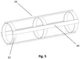
- FIG. 5 shows a possible embodiment of the shaft (11) of the brush structure of a sweeper machine.
- the shaft (11) is formed by an array of tube fragments (12) attached to one another by means of an array of keys (13) corresponding to keyways (9) made in the central hole of each ring (1).
Landscapes
- Engineering & Computer Science (AREA)
- Architecture (AREA)
- Civil Engineering (AREA)
- Structural Engineering (AREA)
- Polishing Bodies And Polishing Tools (AREA)
- Brushes (AREA)
Abstract
Description
- The object of the present invention is a lightweight and easy-to-assemble brush structure, and particularly for sweeper machine brushes.
- Sweeper machines are used on construction sites to collect waste such as dust or gravel generated during milling tasks for lifting pavements in poor condition, in order to facilitate work on site and the adherence of subsequently applied layers, or as finishing work in the construction site prior to painting the pavement.
- Document
ES2244256A1 - The present invention provides a brush structure for a sweeper machine which allows for simpler installation, therefore reducing the time and cost for assembling the filaments for sweeping in each of the rings. Additionally, the present invention has a configuration which allows the weight of the shaft of the brush of the sweeper machine to be reduced.
- The brush structure of a sweeper machine of the present invention is formed by a shaft and a set of rings, said rings bearing the filaments for sweeping. Each of the rings is formed by two parts which are coupled to one another and form the ring for the brush of a sweeper machine. Each of the parts forming the ring for the brush of a sweeper machine is referred to as a "half-ring" (each of the half-rings consists of a ring which can be coupled to the other half-ring to form the ring for the brush of a sweeper machine of the present invention).
- Each of the half-rings has an internal side, which is the side for coupling to the other half-ring to form the ring for the brush of a sweeper machine object of the present invention, and an external side.
- The internal side of each of the half-rings forming the ring for the brush comprises fixing means for fixing to the other half-ring. According to an embodiment option, said fixing means consist of an array of bolts disposed on the internal side of a half-ring, and an array of housings corresponding to said bolts on the internal side of the other half-ring, in such a way that the bolts are introduced in the housings and the internal sides of the two half-rings are attached, making contact with one another. According to an embodiment option, each of the internal sides of each half-ring comprises as many bolts as bolt housings disposed on the internal side of the other half-ring.
- The internal side of each half-ring further comprises an array of U-shaped notches, in such a way that the extremities of the arms of said notches extend towards the perimeter edge of each half-ring. When the half-rings are coupled to one another, the notches of both half-rings coincide, in such a way that once attached they form a U-shaped housing with two exit orifices at the perimeter edge. In this way, and before coupling both half-rings to form the ring for the brush of a sweeper machine, a filament for sweeping, usually made of steel cable, is disposed in each of the notches of a half-ring, the extremities of each filament projecting radially outwards from the half-ring; and once the filaments are disposed in the respective housings of the half-ring, the other half-ring is coupled, with the filaments being fitted in each housing.
- According to an embodiment option, the ring further comprises on its external sides (i.e., on the external side of each of the half-rings) an array of coupling means for coupling to the adjacent ring. The purpose of these coupling means for coupling a ring with the adjacent ring is to transmit the driving power from one ring to another tangentially, preventing the shaft from being the element transmitting all the driving power to each of the rings, and therefore allowing the weight of said shaft, and thereby the weight of the entire brush structure for a sweeper machine, to be reduced.
- Although a solid shaft can be used and the driving power can be transmitted through the key, the shaft is preferably formed by tube fragments attached to one another through one or more linear elements. According to an embodiment option, the tube fragments are attached to one another by means of one or more keys corresponding to the keyways of the rings.
- As a complement to the description provided herein, and for the purpose of helping to make the features of the invention more readily understandable, in accordance with a preferred exemplary embodiment thereof, said description is accompanied by a set of figures constituting an integral part of the same, which by way of illustration and not limitation, represent the following:
-
Figure 1 shows a perspective view of a pair of rings of the brush structure of a sweeper machine coupled to one another, according to an embodiment of the present invention. -
Figure 2 shows a perspective view of a ring of the brush structure of a sweeper machine, in which the two portions forming the ring are uncoupled, according to an embodiment of the present invention. -
Figure 3 shows a perspective view of a pair of rings of the brush structure of a sweeper machine coupled to one another, one of the rings comprising an array of filaments for sweeping, according to an embodiment of the present invention. -
Figure 4 shows a detail of the arrangement of the filaments in one of the notches made in each of the rings of the brush structure of a sweeper machine, according to an embodiment of the present invention. -
Figure 5 shows a perspective view of the shaft of the brush structure of a sweeper machine, according to an embodiment of the present invention. - In light of the aforementioned figures, and in accordance with the adopted numbering, one may observe therein a preferred exemplary embodiment of the invention, which comprises the parts and elements indicated and described in detail below.
- The brush structure of a sweeper machine object of the present invention is formed by a shaft (11) and a set of rings (1), said rings (1) bearing the filaments (10) for sweeping.
- In that sense, as seen in
Figures 1 to 4 , each of the rings of the structure is formed by two half-rings (2). Each of the half-rings (2) comprises on its internal side an array of U-shaped notches (5), in such a way that the extremities of the arms of said notches (5) extend towards the perimeter edge of each half-ring (2). When the half-rings (2) are coupled to one another, the notches (5) of both half-rings coincide, in such a way that once attached they form a U-shaped housing with two exit orifices (6) at the perimeter edge. Therefore, as can be observed particularly inFigure 4 , and before coupling both half-rings (2) to form the ring (1), a filament (10) for sweeping is disposed in each of the notches (5) of one of the half-rings, the extremities of each filament (10) projecting radially outwards from the half-ring (2); and once the filaments (10) are disposed in the respective housings of the half-ring, the other half-ring (2) is coupled, with the filaments (10) being fitted in each housing. - Additionally, each of the half-rings (2) comprises on the internal side fixing means for fixing to the other half-ring (2). In the embodiment shown, said fixing means consist of an array of bolts (3) disposed on the internal sides of the two half-rings (2) forming the ring (1) and an array of housings (4) corresponding to said bolts (3) disposed on the internal sides of the two half-rings (2). In the embodiment shown, the bolts (3) and the housings (4) are disposed alternately in the space formed between the arms of each of the notches (5) in each half-ring (2).
- The ring (1) further comprises on its external sides (i.e., on the external side of each of the half-rings (2)) an array of coupling means for coupling to the adjacent ring. These coupling means consist of a set of protruding portions (7), i.e., protruding above the external side of the ring (1), which are inserted into an array of second notches (8) disposed on the external side of the adjacent ring (1). Preferably, each of the external sides of each ring comprises an array of protruding portions (7) and an array of second notches (8) disposed alternately.
-
Figure 5 shows a possible embodiment of the shaft (11) of the brush structure of a sweeper machine. The shaft (11) is formed by an array of tube fragments (12) attached to one another by means of an array of keys (13) corresponding to keyways (9) made in the central hole of each ring (1).
Claims (7)
- A brush structure for a sweeper machine, formed by a shaft (11) and a set of rings (1) to bear filaments (10) for sweeping, characterised in that each of the rings of the structure is formed by two half-rings (2); each of said half-rings (2) comprising an internal side and an external side, where the internal side of each of the half-rings (2) comprises an array of U-shaped notches (5), in such a way that the extremities of the arms of said notches (5) extend towards the perimeter edge of each half-ring (2); each of the half-rings (2) further comprising mutual coupling means on the internal sides thereof, in such a way that once coupled they form the ring (1), and the notches (5) of both half-rings coincide to form a U-shaped housing with two exit orifices (6) at the perimeter edge of the ring (1), where in each of said housings a filament (10) for sweeping is disposed, the extremities whereof project from the exit orifices (6).
- The brush structure for a sweeper machine according to claim 1, characterised in that the fixing means consist of an array of bolts (3) disposed on the internal sides of the two half-rings (2) forming the ring (1) and an array of housings (4) corresponding to said bolts (3) disposed on the internal sides of the two half-rings (2).
- The brush structure for a sweeper machine according to claim 2, characterised in that the bolts (3) and the housings (4) are disposed alternately in the space formed between the arms of each of the notches (5) in each half-ring (2).
- The brush structure for a sweeper machine according to any of the preceding claims, characterised in that the ring (1) comprises on its external sides, i.e., on the external side of each of the half-rings (2), an array of coupling means for coupling to the adjacent ring.
- The brush structure for a sweeper machine according to claim 4, characterised in that the coupling means for coupling to the adjacent ring consist of a set of protruding portions (7) which are inserted into an array of second notches (8) disposed on the external side of the adjacent ring (1).
- The brush structure for a sweeper machine according to claim 5, characterised in that each of the external sides of each ring comprises an array of protruding portions (7) and an array of second notches (8) disposed alternately.
- The brush structure for a sweeper machine according to any of the preceding claims, characterised in that the shaft (11) is formed by an array of tube fragments (12) attached to one another by means of an array of keys (13) corresponding to keyways (9) made in the central hole of each ring (1).
Applications Claiming Priority (2)
| Application Number | Priority Date | Filing Date | Title |
|---|---|---|---|
| ES202030342A ES2869498B2 (en) | 2020-04-24 | 2020-04-24 | Brush structure for sweeping machine |
| PCT/ES2021/070270 WO2021214366A1 (en) | 2020-04-24 | 2021-04-23 | Structure of a brush for a sweeper machine |
Publications (2)
| Publication Number | Publication Date |
|---|---|
| EP4140358A1 true EP4140358A1 (en) | 2023-03-01 |
| EP4140358A4 EP4140358A4 (en) | 2023-06-21 |
Family
ID=78149183
Family Applications (1)
| Application Number | Title | Priority Date | Filing Date |
|---|---|---|---|
| EP21792823.3A Withdrawn EP4140358A4 (en) | 2020-04-24 | 2021-04-23 | Structure of a brush for a sweeper machine |
Country Status (3)
| Country | Link |
|---|---|
| EP (1) | EP4140358A4 (en) |
| ES (1) | ES2869498B2 (en) |
| WO (1) | WO2021214366A1 (en) |
Families Citing this family (1)
| Publication number | Priority date | Publication date | Assignee | Title |
|---|---|---|---|---|
| EP4599728A1 (en) * | 2022-10-03 | 2025-08-13 | Necematt, S.L. | Roller brush mounting structure for pavement sweepers |
Family Cites Families (5)
| Publication number | Priority date | Publication date | Assignee | Title |
|---|---|---|---|---|
| US553402A (en) * | 1896-01-21 | Brush | ||
| US1970302A (en) * | 1932-09-13 | 1934-08-14 | Charles C Gerhardt | Brush |
| US3839763A (en) * | 1972-07-27 | 1974-10-08 | W Gould | Rotary brush section |
| FR2759264B1 (en) * | 1997-02-13 | 1999-04-16 | Lozerienne Plastique Sa | DEVICE FOR RECEIVING FIBER HARNESSES IN ROLLER BROOMS EQUIPPED WITH CLEANING MACHINES OR APPARATUSES |
| ES2244256B1 (en) * | 2002-09-19 | 2007-02-01 | Necematt, S.L. | USEFUL SPOON-SWEEPER FOR WORKS. |
-
2020
- 2020-04-24 ES ES202030342A patent/ES2869498B2/en not_active Expired - Fee Related
-
2021
- 2021-04-23 EP EP21792823.3A patent/EP4140358A4/en not_active Withdrawn
- 2021-04-23 WO PCT/ES2021/070270 patent/WO2021214366A1/en not_active Ceased
Also Published As
| Publication number | Publication date |
|---|---|
| WO2021214366A1 (en) | 2021-10-28 |
| EP4140358A4 (en) | 2023-06-21 |
| ES2869498A1 (en) | 2021-10-25 |
| ES2869498B2 (en) | 2022-02-24 |
Similar Documents
| Publication | Publication Date | Title |
|---|---|---|
| CN109391056B (en) | Axial gap motor and method for manufacturing rotor | |
| CA1154271A (en) | Flexible couplings | |
| DE60017037T2 (en) | Motor generator with separate core parts | |
| EP1221754A3 (en) | Generator stator cooling design with concavity surfaces | |
| EP2273143B1 (en) | Generator flexible drive coupling | |
| EP0944158A3 (en) | Motor having air-gaps in various types | |
| ITPN960017A1 (en) | ELECTRIC MACHINE, IN PARTICULAR ELECTRIC MOTOR | |
| GB2043207A (en) | Rotary coupling | |
| US4083639A (en) | Shaft end coupling for a dynamoelectric machine | |
| EP4205265A1 (en) | Electric machine arrangement | |
| EP3050194A2 (en) | Assembly with an electric machine | |
| US925271A (en) | Core-spacing member for dynamo-electric machines. | |
| US1185208A (en) | Flexible coupling. | |
| WO2021214366A1 (en) | Structure of a brush for a sweeper machine | |
| JPH0610641U (en) | Rotation transmission shock absorber | |
| CA2454663C (en) | Wide-angle constant-velocity joint, with arrangement for reducing the stresses of the internal members | |
| CA1100772A (en) | Shaft end coupling for a dynamoelectric machine | |
| WO2022259004A1 (en) | Rotor for agricultural biomass-cutting machine | |
| JPH0527589Y2 (en) | ||
| JP5736771B2 (en) | Rotating electric machine stator | |
| US20110273055A1 (en) | Method and Apparatus for Retaining Laminations of a Stator of an Electrical Machine | |
| DE102021116794B4 (en) | Torque transmission device and hybrid device | |
| RU2815589C1 (en) | Safety splined connection | |
| CN218992170U (en) | Driving shaft coupler | |
| CN217440090U (en) | Tunnel escape pipe adopting hasp type connection |
Legal Events
| Date | Code | Title | Description |
|---|---|---|---|
| STAA | Information on the status of an ep patent application or granted ep patent |
Free format text: STATUS: THE INTERNATIONAL PUBLICATION HAS BEEN MADE |
|
| PUAI | Public reference made under article 153(3) epc to a published international application that has entered the european phase |
Free format text: ORIGINAL CODE: 0009012 |
|
| STAA | Information on the status of an ep patent application or granted ep patent |
Free format text: STATUS: REQUEST FOR EXAMINATION WAS MADE |
|
| 17P | Request for examination filed |
Effective date: 20221121 |
|
| AK | Designated contracting states |
Kind code of ref document: A1 Designated state(s): AL AT BE BG CH CY CZ DE DK EE ES FI FR GB GR HR HU IE IS IT LI LT LU LV MC MK MT NL NO PL PT RO RS SE SI SK SM TR |
|
| STAA | Information on the status of an ep patent application or granted ep patent |
Free format text: STATUS: EXAMINATION IS IN PROGRESS |
|
| A4 | Supplementary search report drawn up and despatched |
Effective date: 20230519 |
|
| RIC1 | Information provided on ipc code assigned before grant |
Ipc: E01H 1/05 20060101ALI20230512BHEP Ipc: A46B 13/00 20060101ALI20230512BHEP Ipc: A46B 3/16 20060101ALI20230512BHEP Ipc: A46B 3/14 20060101AFI20230512BHEP |
|
| 17Q | First examination report despatched |
Effective date: 20230602 |
|
| DAV | Request for validation of the european patent (deleted) | ||
| DAX | Request for extension of the european patent (deleted) | ||
| STAA | Information on the status of an ep patent application or granted ep patent |
Free format text: STATUS: THE APPLICATION IS DEEMED TO BE WITHDRAWN |
|
| 18D | Application deemed to be withdrawn |
Effective date: 20231013 |