EP4139820B1 - Booteinrichtung für ein computerelement und verfahren zum booten eines computerelements - Google Patents
Booteinrichtung für ein computerelement und verfahren zum booten eines computerelements Download PDFInfo
- Publication number
- EP4139820B1 EP4139820B1 EP21735212.9A EP21735212A EP4139820B1 EP 4139820 B1 EP4139820 B1 EP 4139820B1 EP 21735212 A EP21735212 A EP 21735212A EP 4139820 B1 EP4139820 B1 EP 4139820B1
- Authority
- EP
- European Patent Office
- Prior art keywords
- code
- software component
- protection
- booting
- hash
- Prior art date
- Legal status (The legal status is an assumption and is not a legal conclusion. Google has not performed a legal analysis and makes no representation as to the accuracy of the status listed.)
- Active
Links
Images



Classifications
-
- G—PHYSICS
- G06—COMPUTING OR CALCULATING; COUNTING
- G06F—ELECTRIC DIGITAL DATA PROCESSING
- G06F21/00—Security arrangements for protecting computers, components thereof, programs or data against unauthorised activity
- G06F21/50—Monitoring users, programs or devices to maintain the integrity of platforms, e.g. of processors, firmware or operating systems
- G06F21/57—Certifying or maintaining trusted computer platforms, e.g. secure boots or power-downs, version controls, system software checks, secure updates or assessing vulnerabilities
- G06F21/575—Secure boot
-
- G—PHYSICS
- G06—COMPUTING OR CALCULATING; COUNTING
- G06F—ELECTRIC DIGITAL DATA PROCESSING
- G06F9/00—Arrangements for program control, e.g. control units
- G06F9/06—Arrangements for program control, e.g. control units using stored programs, i.e. using an internal store of processing equipment to receive or retain programs
- G06F9/44—Arrangements for executing specific programs
- G06F9/4401—Bootstrapping
-
- H—ELECTRICITY
- H04—ELECTRIC COMMUNICATION TECHNIQUE
- H04L—TRANSMISSION OF DIGITAL INFORMATION, e.g. TELEGRAPHIC COMMUNICATION
- H04L9/00—Cryptographic mechanisms or cryptographic arrangements for secret or secure communications; Network security protocols
- H04L9/32—Cryptographic mechanisms or cryptographic arrangements for secret or secure communications; Network security protocols including means for verifying the identity or authority of a user of the system or for message authentication, e.g. authorization, entity authentication, data integrity or data verification, non-repudiation, key authentication or verification of credentials
- H04L9/3236—Cryptographic mechanisms or cryptographic arrangements for secret or secure communications; Network security protocols including means for verifying the identity or authority of a user of the system or for message authentication, e.g. authorization, entity authentication, data integrity or data verification, non-repudiation, key authentication or verification of credentials using cryptographic hash functions
- H04L9/3242—Cryptographic mechanisms or cryptographic arrangements for secret or secure communications; Network security protocols including means for verifying the identity or authority of a user of the system or for message authentication, e.g. authorization, entity authentication, data integrity or data verification, non-repudiation, key authentication or verification of credentials using cryptographic hash functions involving keyed hash functions, e.g. message authentication codes [MACs], CBC-MAC or HMAC
-
- G—PHYSICS
- G06—COMPUTING OR CALCULATING; COUNTING
- G06F—ELECTRIC DIGITAL DATA PROCESSING
- G06F2221/00—Indexing scheme relating to security arrangements for protecting computers, components thereof, programs or data against unauthorised activity
- G06F2221/03—Indexing scheme relating to G06F21/50, monitoring users, programs or devices to maintain the integrity of platforms
- G06F2221/034—Test or assess a computer or a system
Definitions
- the present invention relates to a boot device for a computer element for booting the computer element. Furthermore, the present invention relates to a computer element with a boot device and a method for booting a computer element.
- the boot process also called the "start process”
- start process the boot process of the computer element secure in order to ensure that the expected functionality is realized when booting.
- the next software loaded is integer.
- a digital signature, a hash value or the like of the loaded software can be determined and checked before it is executed.
- the protection method used to check the loaded software as well as the digital signature, the hash value or the like used can form an unchangeable program code of the boot device, which is specified by the manufacturer of the boot device.
- the relevant state of the art is in US8560823 to find.
- an object of the present invention is to enable improved booting of a computer element.
- the protection code can be changed at least partially from outside the boot device, a user of the boot device (for example an end user of the boot device or a machine manufacturer who integrates the computer element into his machine) has in particular the possibility of opting for a specific cryptographic protection method.
- the user of the boot device can implement his own protection solution without having to rely on the solution implemented by the manufacturer of the boot device.
- a separate implementation for the authentication, integrity check and/or confidentiality protection of the boot device can be defined.
- the protection code is updatable and can, for example, be modified so that a new (modified) protection code also offers protection against new technologies, such as quantum computer technologies. This can enable cryptoagility and increase the protection offered by the protection code.
- the boot device can be part of the computer element. It can also be referred to as a processing device, computing device or process device.
- the boot device is particularly suitable for booting the computer element.
- the boot device can be a processor chip, in particular a closed processor chip.
- the boot device is in particular a non-destructively accessible component that can only be accessed non-destructively via permitted interfaces, for example.
- the protection value is a trustworthy piece of information that is used to check the integrity of the software component by the protection unit.
- the component hash value is in particular a hash value of the software component that is assigned to the software component or is determined by the protection unit.
- the comparison hash value can be a hash value that is part of the protection code and is used for comparison with the component hash value. If the component hash value is identical to the comparison hash value, the protection unit determines, for example, that the software component is integer.
- the protection code comprises a changeable cryptographic code, in particular a changeable hash code, wherein the protection unit is suitable for executing the changeable hash code during the integrity check of the software component in order to carry out a hash value comparison and/or executing the changeable cryptographic code in order to carry out a cryptographic encryption, decryption and/or checking.
- the hash code defines in particular how a hash value check of the software component is carried out. During the hash value check, a hash value of the software component (component hash value) is determined in accordance with the hash code and compared with a comparison hash value.
- the boot device only allows the change in one of the cases mentioned above. If the boot device detects a change attempt that does not follow a permitted change process, the boot device can prohibit the change and/or issue a warning signal that warns of an unauthorized change (or a potential attack). These measures can increase the security of the Boot setup must be increased because only authorized users can make changes to the protection code.
- the manufacturer of the boot device can, for example, stipulate that changes to the protection code may only be made via an interface of the protection unit provided by a manufacturer of the boot device (for example via JTAG, Joint Test Action Group, whereby the interface can be deactivated during operation of the boot device, for example by eFuses), only according to a predetermined standard, using a predetermined change file provided by the manufacturer, with a predetermined configuration device provided by the manufacturer (for example via JTAG) and/or once (for this purpose the memory unit can include a one-time writable area, also known as OTP - one time programmable area). It is also possible to only allow writing to the memory unit and changing the protection code when the computer element is in configuration mode and the eFuse has not yet been burned.
- a change requirement code can be stored in the storage unit as program code, which is executed to check the admissibility of the change.
- the change requirement code cannot be changed and is determined in particular by the manufacturer of the boot device. It is also conceivable that the storage unit itself has properties that only allow certain changes to the protection code.
- the boot device is designed as a computer chip.
- the computer chip is in particular a processor chip (CPU).
- the computer element comprises a computer, an IO module, a CPU module or an FPGA system that is configurable as a software component when booting using a bit stream.
- the software component comprises hardware and/or software and is in particular a first bootloader stage.
- a computer element with a boot device according to the first aspect or according to an embodiment of the first aspect is proposed.
- a computer program product comprising instructions which, when the program is executed by a boot device (in particular by a boot device according to the first aspect or according to an embodiment of the first aspect), cause the boot device to carry out the method according to the third aspect is proposed.
- a computer program product such as a computer program means
- the Fig. 1 shows a computer element 1 with a boot device 2 according to a first embodiment.
- the computer element 1 comprises, in addition to the boot device 2, a software component 6.
- the computer element comprises a memory unit 3 for storing a protection code 4 and a protection unit 5.
- the arrow in the Fig. 1 indicates that the protection unit 5 has access to the software component 6.
- the computer element 1 of the Fig. 1 is an industrial automation system.
- the boot device 2 is designed as a processor (CPU) and serves, among other things, to start up (boot) the computer element 1.
- the method step S0 designates the start of the method described.
- the protection code 4 is stored in the memory unit 3.
- the protection code 4 is originally stored by a manufacturer of the processor 2.
- the protection code 4 is a program that is executed by the protection unit 5 when the computer element 1 is booted to check the integrity of the software component 6. It is also possible that the manufacturer of the processor 2 does not store an initial protection code 4, but merely provides storage space in the memory unit 3 that the user of the processor 2 can use for the protection code 4.
- the protection code 4 is at least partially modified from outside the processor 2.
- a user of the processor 2 accesses the storage unit 3 in the field and modifies the previously stored protection code 4 so that it meets desired requirements.
- the user can modify both cryptographic keys, hash values or the like that are used in the integrity check of the software component 6, as well as program parts that define the integrity check process itself.
- the user may use a device provided by the manufacturer of the processor 2 for this purpose.
- the protection unit 3 carries out an integrity check of the software component 6. To do this, the protection unit 3 executes the protection code 4 and applies it to information that is part of the software of the software component 6.
- the processor 2 of the Fig. 1 enables the user to flexibly change the protection code 4, which means that the integrity check of the software component 6 is carried out with greater security. This makes the entire boot process more secure.
- the Fig. 3 shows a method for booting the computer element 1 of the Fig. 1 according to a second embodiment.
- the method of the figure comprises - as well as the method of Fig. 2 - steps S0 to S3.
- the method of Fig. 3 the additional steps S4, S5 and S6.
- step S5 Depending on whether the protection unit 5 determines in the integrity check step S3 that the software component 6 is integer or not (step S4), either step S5 or step S6 is carried out. If it is determined in steps S3 and S4 that the software component 6 is integer, the software component 6 is booted by the protection unit 5 or by an additional boot unit (in the Fig. 1 not shown) is executed (step S5). If it is determined in steps S3 and S4 that the software component 6 is not integer, a corresponding warning signal is issued in step S6.
- the Fig. 4 shows a computer element 1 with a boot device 2 according to a second embodiment.
- a signature verification can be updated in the first boot step and, if necessary, replaced by a quantum computer-resistant signature method.
- a hash code 8 is stored in the protection unit 5, which is designed as a boot ROM. This hash code is a program with which the protection unit 5 carries out a hash value test on the software component 6.
- the software component 6 is in the example of Fig. 4 stored in an internal memory 9 of the computer element 1.
- the software component 6 comprises an associated component signature 6a and an associated component key 6b, which is a public key.
- the memory unit 3 comprises several eFuses 7a - 7c, which are provided empty by the manufacturer of the processor 2 and can be programmed by the user of the processor 2 and form at least part of the protection code 4.
- the user burns protection values into the eFuses 7a - 7c. This is preferably done in a secure environment.
- the user has burned a public key hash value into the eFuse 7a and a signature verification code hash value into the eFuse 7b.
- the eFuse 7c and other eFuses include additional public key hash values and signature verification code hash values. Old hash values can be invalidated either automatically or by burning a dedicated eFuse 7a - 7c.
- the signature verification code 10 In parallel with updating the hash values, the signature verification code 10, the component signature 6a and the component key 6b are also updated.
- the updates made by the processor 2 according to the second embodiment ( Fig. 4 ) are particularly relevant when the crypto algorithm (for example an asymmetric signature method) of the signature verification code 10 is broken or has vulnerabilities, but not the hash code 8.
- the Fig. 5 shows a method for booting the computer element 1 of the Fig. 4
- the process starts with step S0.
- the protection unit 5 receives the signature verification code 10 from the memory 9 (in the Fig. 4 represented by an arrow) and hashes it with the pre-stored hash code 8, thereby obtaining a first hash result (component hash value).
- step S8 this first hash result is compared with the signature verification code hash value of the eFuse 7b. If the comparison shows that the hash values are not identical, an error is reported in step S9 and the method is terminated. If the comparison in step S8 shows that the hash values are identical, the process continues with step S9.
- the protection unit 5 receives access to the software component 6 with the component signature 6a and the component key 6b.
- step S10 the protection unit 5 hashes the public key 6b, thereby obtaining a second hash result.
- step S11 it is checked whether the second hash result and the public key hash value in the eFuse 7a are identical. If they are not identical, an error is reported in step S9 and the process is terminated.
- step S12 the signature verification code 10 is used to check whether the component signature 6a is valid. If it is determined in step S12 that the component signature 6a is not valid, an error is reported in step S9 and the method is terminated. If it is determined in step S12 that the component signature 6a is valid, the software component is executed in step S5.
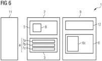
- the Fig. 6 shows a computer element 1 with a boot device 2 according to a third embodiment and relates to the know-how protection of FPGA bit streams. Symmetric cryptographic encryption methods are usually used for this, which are firmly integrated into the hardware by the hardware manufacturer.
- the processor 2 of the Fig. 6 it allows the use of a user-implemented method for authenticated decryption. To do this, the user burns the secret key into eFuses. This is explained in more detail below.
- the computer element 1 here is an FPGA system with an FPGA 11, a processor 2 and a memory 9.
- An FPGA bit stream 6 is stored in the memory 9 as a software component, which comprises authentication information 6c (“Authentication tag”) and an authenticated decryption code 12.
- the FPGA bit stream 6 is encrypted and is decrypted by the boot device 2 when the computer element 1 is started and used to configure the FPGA 11.
- the processor 2 of the Fig. 6 is identical to processor 2 from the Fig. 4 However, the protection values stored in the eFuses 7a - 7b are different.
- the protection values stored in the eFuses 7a - 7b are different.
- the eFuse 7c and further eFuses (not shown) contain further secret symmetric keys and authenticated decryption code hash values.
- the protection values contained in the eFuses 7a - 7c can be set in the field from outside the processor 2. Old hash values and keys can be invalidated either automatically or by burning a dedicated eFuse 7a - 7c.
- the secret symmetric key In contrast to the boot device of the second embodiment ( Fig. 4 ), in symmetric cryptography the secret symmetric key must be stored completely in eFuses 7a - 7c (not readable from outside). Therefore, a variable length is preferably possible for the secret symmetric key, since the key length depends on the selected method and the selected security level.
- the Fig. 7 shows a method for booting the computer element 1 of the Fig. 6
- the process starts with step S0.
- the authenticated decryption code 12 is hashed with the hash code 8, thereby obtaining a third hash result.
- step S14 the third hash result is compared with the authenticated decryption code hash value from the eFuse 7b. If the hash values compared in step S14 are not identical, an error is reported in step S9 and the method is terminated. If the hash values compared in step S14 are identical, the protection unit 5 receives access to the FPGA bit stream 6 and the authentication information 6c contained therein (step S15 of the Fig. 7 ).
- a step S16 the protection unit 5 decrypts the FPGA bit stream 6 based on the authenticated decryption key 12 using the secret symmetric key in the eFuse 7a and calculates comparison authentication information.
- the protection unit 5 compares the authentication information 6c with the comparison authentication information (checking the authentication information). If the check in step S17 shows a discrepancy, an error is reported in step S9 and the method is terminated. If the check in step S17 shows that the authentication information 6c is identical to the comparison authentication information, the protection unit 5 configures the FPGA 11 with the decrypted FPGA bit stream 6 in step S18.
- the Fig. 8 shows a computer element 1 with a boot device 2 according to a fourth embodiment.
- the memory unit 3 comprises several memory areas 3a, 3b, of which in the Fig. 8 only two are shown.
- the hash code 8, a cryptographic code, the signature verification code 10, the authenticated decryption code 12 or general "root-of-trust functions" can be defined and changed in these memory areas 3a, 3b from outside the boot device 2.
- the memory areas 3a, 3b can be written to once and can be designed, for example, as programmable read-only memories (PROM). Alternatively, rewritable memories can be used, which are particularly restricted to write access.
- the memory areas 3a, 3b only allow changes, for example, if the change is made in accordance with a permitted change process. namely, for example, only via an interface provided by a manufacturer of the boot device (for example via JTAG, Joint Test Action Group, where the interface can be deactivated during operation of the boot device, for example by eFuses); only according to a predetermined standard, using a predetermined change file provided by the manufacturer; only with a predetermined configuration device provided by the manufacturer (for example via JTAG) and/or only once. It is also possible to only allow writing to the memory unit 5 and changing the protection code 4 when the computer element 1 is in configuration mode and the eFuse 7a - 7c has not yet been burned.
- FIG. 8 A signature verification code 10 and an associated public key are stored in the memory area 3a. Booting is carried out using the processor 2 of the Fig. 8 analogous to the Fig. 4 to 7 described boot processes.
- the memory 9 described is part of the boot device 2 (internal memory), but it can also be present outside the boot device 2 (external memory).
Landscapes
- Engineering & Computer Science (AREA)
- Computer Security & Cryptography (AREA)
- Software Systems (AREA)
- Theoretical Computer Science (AREA)
- General Engineering & Computer Science (AREA)
- Computer Hardware Design (AREA)
- Physics & Mathematics (AREA)
- General Physics & Mathematics (AREA)
- Power Engineering (AREA)
- Computer Networks & Wireless Communication (AREA)
- Signal Processing (AREA)
- Storage Device Security (AREA)
Description
- Die vorliegende Erfindung betrifft eine Booteinrichtung für ein Computerelement zum Booten des Computerelements. Ferner betrifft die vorliegende Erfindung ein Computerelement mit einer Booteinrichtung, sowie ein Verfahren zum Booten eines Computerelements.
- Zum Integritätsschutz eines Computerelements kann es wichtig sein, den Bootvorgang (auch "Startvorgang") des Computerelements sicher zu gestalten, um sicherzustellen, dass beim Booten die erwartete Funktionalität realisiert wird. So wird zum Beispiel im Rahmen eines sicheren Bootvorgangs (Engl. "secure boot") geprüft, ob eine jeweils als nächste geladene Software integer ist. Hierzu kann eine digitale Signatur, ein Hashwert oder dergleichen der geladenen Software ermittelt und geprüft werden, bevor diese ausgeführt wird. Das zur Prüfung der geladenen Software verwendete Schutzverfahren sowie die verwendete digitale Signatur, der verwendete Hashwert oder dergleichen können einen unveränderbaren Programmcode der Booteinrichtung bilden, der durch den Hersteller der Booteinrichtung festgelegt ist. Relevanter Stand der Technik ist in
US8560823 zu finden. - Vor diesem Hintergrund besteht eine Aufgabe der vorliegenden Erfindung darin, ein verbessertes Booten eines Computerelements zu ermöglichen.
- Gemäß einem ersten Aspekt wird eine Booteinrichtung für ein Computerelement zum Booten des Computerelements vorgeschlagen. Die Booteinrichtung umfasst:
- eine Speichereinheit zum Speichern eines Schutzcodes; und
- eine Schutzeinheit zur Integritätsprüfung einer Softwarekomponente des Computerelements anhand des Schutzcodes, wobei die Booteinrichtung geeignet ist, die Softwarekomponente zum Booten des Computerelements auszuführen; wobei
- der Schutzcode von außerhalb der Booteinrichtung zumindest teilweise veränderbar ist.
- Dadurch, dass der Schutzcode zumindest teilweise von außerhalb der Booteinrichtung veränderbar ist, hat ein Nutzer der Booteinrichtung (zum Beispiel ein Endnutzer der Booteinrichtung oder ein Maschinenhersteller, der das Computerelement in seine Maschine integriert) insbesondere die Möglichkeit, sich für ein spezifisches kryptographisches Schutzverfahren zu entscheiden. Der Nutzer der Booteinrichtung kann eine eigene Schutzlösung implementieren, ohne sich auf die vom Hersteller der Booteinrichtung implementierte Lösung verlassen zu müssen. Durch das Verändern des Schutzcodes kann eine eigene Implementierung für die Authentifizierung, Integritätsprüfung und/oder den Vertraulichkeitsschutz der Booteinrichtung definiert werden.
- Darüber hinaus ist der Schutzcode aktualisierbar und kann zum Beispiel derart verändert werden, dass ein neuer (veränderter) Schutzcode auch gegenüber neuen Technologien, wie zum Beispiel Quantencomputertechnologien, Schutz bietet. Dadurch kann die Kryptoagilität ermöglicht werden und ein Schutz, den der Schutzcode bietet, kann erhöht werden.
- Die Booteinrichtung kann Teil des Computerelements sein. Sie kann auch als Verarbeitungseinrichtung, Rechenvorrichtung oder Prozessvorrichtung bezeichnet werden. Die Booteinrichtung ist insbesondere geeignet, das Computerelement zu Booten. Die Booteinrichtung kann ein Prozessor-Chip, insbesondere ein abgeschlossener Prozessor-Chip, sein. Bei der Booteinrichtung handelt es sich insbesondere um eine nichtzerstörungsfrei zugreifbare Komponente, auf die beispielsweise nur über erlaubte Schnittstellen zerstörungsfrei zugegriffen werden kann.
- Unter einem Booten wird insbesondere ein Startprozess, also ein Hochfahren, des Computerelements bezeichnet. Insbesondere wird beim Booten das Betriebssystem des Computerelements geladen. Im Rahmen des Bootens wird zumindest eine Softwarekomponente (Startprogramm-Komponente) geladen und ausgeführt, um das Computerelement zu starten/booten. Bei der Softwarekomponente handelt es sich um Software. Die Softwarekomponente ist beispielsweise ein Bootloader.
- Das Computerelement kann ein Computer oder Teil davon sein. Ferner kann das Computerelement ein Gerät mit mehreren Komponenten bezeichnen, die beim Hochfahren des Computerelements geladen werden. Hierzu zählen zum Beispiel IO-Module (input/output Module, auch Ausgabe-/Eingabemodule), CPU-Module (Central Processing Unit Module, auch Prozessormodule), sowie FPGAs (Field Programmable Gate Array, auch programmierbarer Logikgatter). Das Computerelement findet beispielsweise im industriellen Umfeld Anwendung, insbesondere in einem industriellen Automatisierungssystem. Die Möglichkeit, den Schutzcode zu verändern, ist im industriellen Umfeld besonders wichtig, weil dort besonders hohe Anforderungen an die Sicherheit gestellt werden und weil industrielle Geräte häufig über viele Jahre im Feld sind und deren Schutzmechanismen ohne Aktualisierung altern und den Schutz reduzieren.
- Der Schutzcode kann als eine Ablaufvorschrift, ein Programmcode und/oder ein ausführbarer Befehl zur Implementierung einer Schutzfunktion betrachtet werden. Der Schutzcode kann durch die Speichereinheit ausgeführt werden, um die Integrität der Softwarekomponente zu prüfen. Die Softwarekomponente ist integer, falls sich nach ihrer Herstellung nicht verändert wurde oder zumindest nicht unzulässig verändert wurde.
- Der Schutzcode ist beispielsweise durch einen Nutzer (Endnutzer oder Maschinenhersteller) oder durch eine externe Vorrichtung von außerhalb der Booteinrichtung veränderbar. Veränderbar bedeutet insbesondere, dass ein existierender Schutzcode zumindest teilweise abgeändert, umgeschrieben ergänzt und/oder gelöscht wird. Veränderbar kann auch bedeuten, dass der Schutzcode von außerhalb der Booteinrichtung festlegbar ist. Es ist beispielsweise möglich, einen durch einen Hersteller der Booteinrichtung festgelegten Schutzcode im Feld zu ändern, oder einen initialen Schutzcode im Feld erstmalig festzulegen (falls der Hersteller der Booteinrichtung keinen Schutzcode festgelegt hat).
- Bei der Veränderung des Schutzcodes handelt es sich insbesondere um eine durch den Hersteller der Booteinrichtung ermöglichte und durch den Nutzer der Booteinrichtung veranlasste und/oder erwünschte Änderung des Schutzcodes.
- Die jeweilige Einheit, insbesondere die Speichereinheit oder die Schutzeinheit, kann hardwaretechnisch und/oder auch softwaretechnisch implementiert sein.
- Gemäß einer Ausführungsform umfasst die Speichereinheit zumindest eine eFuse, wobei der Schutzcode durch Einbrennen eines Schutzwerts in die eFuse einmalig beschreibbar ist.
- Der Schutzcode wird durch Einbrennen eines Schutzwerts in die eFuse verändert. Die eFuse, auch "electronic fuse" (elektronische Sicherung), bezeichnet einen irreversiblen, unumkehrbaren Teil der Booteinrichtung, die lediglich ein einziges Mal veränderbar (nämlich festlegbar) ist. Zum Festlegen des Schutzcodes mit der eFuse können Bits in die eFuse gebrannt werden. Der Hersteller der Booteinrichtung sieht insbesondere zumindest eine "leere", nicht festgelegte eFuse in der Booteinrichtung vor, die durch den Nutzer brennbar (konfigurierbar) ist.
- Gemäß einer weiteren Ausführungsform umfasst der Schutzwert einen Vergleichshashwert und/oder einen kryptographischen Schlüssel, wobei die Schutzeinheit geeignet ist, bei der Integritätsprüfung der Softwarekomponente:
- einen Komponentenhashwert der Softwarekomponente mit dem Vergleichshashwert zu vergleichen, und/oder
- eine der Softwarekomponente zugeordneten kryptographisch geschützte Information anhand des kryptographischen Schlüssels zu entschlüsseln und/oder zu überprüfen.
- Der Schutzwert ist insbesondere eine vertrauenswürdige Information, die zur Integritätsprüfung der Softwarekomponente durch die Schutzeinheit verwendet wird.
- Der Komponentenhashwert ist insbesondere ein Hashwert der Softwarekomponente, der der Softwarekomponente zugewiesen ist oder durch die Schutzeinheit ermittelt wird. Der Vergleichshashwert kann ein Hashwert sein, der Teil des Schutzcodes ist und zum Vergleich mit dem Komponentenhashwert dient. Falls der Komponentenhashwert mit dem Vergleichshashwert identisch ist, bestimmt die Schutzeinheit zum Beispiel, dass die Softwarekomponente integer ist.
- Der kryptographische Schlüssel kann ein geheimer symmetrischer Schlüssel, ein öffentlicher Schlüssel oder dergleichen sein. Unter dem kryptographischen Schlüssel kann auch ein kryptographischer Prüfwert verstanden werden, der ein Message Authentication Code (MAC, auch "Nachrichtenauthentifizierungscode"), eine digitale Signatur oder dergleichen sein kann.
- Gemäß einer weiteren Ausführungsform umfasst der Schutzcode einen veränderbaren kryptographischen Code, insbesondere einen veränderbaren Hashcode, wobei die Schutzeinheit geeignet ist, bei der Integritätsprüfung der Softwarekomponente den veränderbaren Hashcode auszuführen, um einen Hashwertvergleich durchzuführen und/oder den veränderbaren kryptographischen Code auszuführen, um eine kryptographische Verschlüsselung, Entschlüsselung und/oder Prüfung durchzuführen.
- Der der kryptographische Code (zum Beispiel der Hashcode) ist insbesondere ein Software-Programmcode, der Teil des Schutzcodes ist und zur Integritätsprüfung ausgeführt wird. Der kryptographische Code definiert insbesondere, gemäß welchem kryptographischen Algorithmus die der Softwarekomponente zugeordneten kryptographisch geschützte Information gehandhabt und/oder hinsichtlich der Integrität der Softwarekomponente geprüft wird.
- Der Hashcode definiert dabei insbesondere, wie eine Hashwertprüfung der Softwarekomponente durchgeführt wird. Bei der Hashwertprüfung wird insbesondere ein Hashwert der Softwarekomponente (Komponentenhashwert) gemäß dem Hashcode ermittelt und mit einem Vergleichshashwert verglichen.
- Gemäß einer weiteren Ausführungsform ist die Booteinrichtung eingerichtet, die Änderung des Schutzcodes von außerhalb der Booteinrichtung nur zuzulassen, falls:
- die Booteinrichtung erkennt, dass die Änderung des Schutzcodes über eine durch einen Hersteller der Booteinrichtung vorgesehene Schnittstelle der Schutzeinheit erfolgt; und/oder
- die Booteinrichtung erkennt, dass die Änderung des Schutzcodes gemäß einem vorbestimmten Standard und/oder anhand einer vorbestimmten Änderungsdatei, die durch den Hersteller der Booteinrichtung vorgegeben sind, erfolgt; und/oder
- die Booteinrichtung erkennt, dass die Änderung des Schutzcodes mit einem vorbestimmten Konfigurationsgerät vom Hersteller erfolgt; und/oder
- die Booteinrichtung lediglich eine einmalige Änderung eines jeweiligen Bereichs des Schutzcodes zulässt und die Booteinrichtung erkennt, dass es sich bei der Änderung um die erste Änderung des Schutzcodes des jeweiligen Bereichs handelt.
- Die Booteinrichtung lässt die Änderung insbesondere nur in einem der zuvor genannten Fälle zu. Falls die Booteinrichtung einen Änderungsversuch erkennt, der nicht gemäß einem erlaubten Änderungsprozess erfolgt, kann die Booteinrichtung die Änderung verbieten und/oder ein Warnsignal ausgeben, dass vor einer nicht zulässigen Änderung (oder einem potentiellen Angriff) warnt. Durch diese Maßnahmen kann die Sicherheit der Booteinrichtung erhöht werden, weil nur zugelassene Nutzer Änderungen an dem Schutzcode durchführen können.
- Der Hersteller der Booteinrichtung kann zum Beispiel vorschreiben, dass Änderungen des Schutzcodes nur über eine durch einen Hersteller der Booteinrichtung vorgesehene Schnittstelle der Schutzeinheit (zum Beispiel über JTAG, Joint Test Action Group, wobei die Schnittstelle beispielsweise im Betrieb der Booteinrichtung deaktiviert werden kann, zum Beispiel durch eFuses), nur gemäß einem vorbestimmten Standard, anhand einer vom Hersteller bereitgestellten vorbestimmten Änderungsdatei, mit einem vom Hersteller bereitgestellten vorbestimmten Konfigurationsgerät (beispielsweise über JTAG) und/oder einmalig (hierzu kann die Speichereinheit einen einmalig beschreibbaren Bereich, auch OTP - one time programmable Bereich, umfassen) erfolgen dürfen. Es ist auch möglich, das Beschreiben der Speichereinheit und das Verändern des Schutzcodes nur zuzulassen, wenn sich das Computerelement im Konfigurationsmodus befindet und die eFuse noch nicht gebrannt wurde.
- Zur Erkennung, ob die Änderung gemäß den beschriebenen Voraussetzungen erfüllt wird, kann in der Speichereinheit ein Änderungsvoraussetzungscode als Programmcode gespeichert sein, der ausgeführt wird, um die Zulässigkeit der Änderung zu prüfen. Der Änderungsvoraussetzungscode ist nicht veränderbar und insbesondere durch den Hersteller der Booteinrichtung festgelegt. Es ist auch denkbar, dass die Speichereinheit selbst Eigenschaften hat, die nur bestimmte Änderungen am Schutzcode zulassen.
- Gemäß einer weiteren Ausführungsform ist die Booteinrichtung als ein Computerchip ausgebildet.
- Bei dem Computerchip handelt es sich insbesondere um ein Prozessorchip (CPU).
- Gemäß einer weiteren Ausführungsform umfasst das Computerelement einen Computer, ein IO-Modul, ein CPU-Modul oder ein FPGA-System, das beim Booten anhand eines Bitstroms als Softwarekomponente konfigurierbar ist.
- Gemäß einer weiteren Ausführungsform umfasst die Softwarekomponente Hardware und/oder Software und ist insbesondere ein erster Bootloader-Schritt (Engl.: "first bootloader stage").
- Gemäß einer weiteren Ausführungsform umfasst die Booteinrichtung ferner eine Booteinheit zum Ausführen der Softwarekomponente, falls die Schutzeinheit durch die Integritätsprüfung bestimmt, dass die Softwarekomponente alle Integritätserfordernisse erfüllt.
- Gemäß einer weiteren Ausführungsform ist die Schutzeinheit geeignet, zur Integritätsprüfung der Softwarekomponente:
- einen Signaturverifikationscode mit einem Hashcode der Booteinrichtung zu hashen, um ein erstes Hashergebnis zu erhalten;
- das erste Hashergebnis mit einem Signaturverifikationscode-Hashwert der Speichereinheit zu vergleichen;
- falls der Vergleich des ersten Hashergebnisses mit dem Signaturverifikationscode-Hashwert ergibt, dass das erste Hashergebnis und der Signaturverifikationscode-Hashwert identisch sind:
- die Softwarekomponente inklusive einer Signatur der Softwarekomponente und eines öffentlichen Schlüssels der Softwarekomponente aus der Softwarekomponente zu erhalten;
- den öffentlichen Schlüssel der Softwarekomponente mit dem Hashcode der Booteinrichtung zum Erhalten eines zweiten Hashergebnisses zu hashen;
- das zweite Hashergebnis mit einem öffentlichen-Schlüssel-Hashwert der Speichereinheit zu vergleichen;
- falls der Vergleich des zweiten Hashergebnisses mit dem öffentlichen-Schlüssel-Hashwert ergibt, dass das zweite Hashergebnis und der öffentliche-Schlüssel-Hashwert identisch sind, die Signatur der Softwarekomponente anhand des Signaturverifikationscodes zu prüfen; und
- falls das Prüfen der Signatur der Softwarekomponente ergibt, dass die Signatur korrekt ist, die Softwarekomponente auszuführen.
- Gemäß einer weiteren Ausführungsform ist das Computerelement ein FPGA-System und die Schutzeinheit ist geeignet, zur Integritätsprüfung und/oder Entschlüsselung der Softwarekomponente:
- einen authentifizierten Entschlüsselungscode mit einem Hashcode der Booteinrichtung zum Erhalten eines dritten Hashergebnisses zu hashen;
- das dritte Hashergebnis mit einem authentifizierten Entschlüsselungscode-Hashwert der Speichereinheit zu vergleichen;
- falls der Vergleich des dritten Hashergebnisses mit dem authentifizierten Entschlüsselungscode-Hashwert ergibt, dass das dritte Hashergebnis und der authentifizierte Entschlüsselungscode-Hashwert identisch sind:
- die Softwarekomponente, welche als ein FPGA-Bitstrom ausgebildet ist, inklusive einer Authentifizierungsinformation der Softwarekomponente durch die Booteinrichtung zu erhalten;
- den FPGA-Bitstrom anhand des Authentifizierten Entschlüsselungscodes (und insbesondere anhand eines geheimen symmetrischen Schlüssels) zu entschlüsseln;
- die Authentifizierungsinformation der Softwarekomponente zu prüfen; und
- falls die Prüfung der Authentifizierungsinformation erfolgreich ist, ein FPGA des FPGA-Systems mit dem entschlüsselten Bitstrom zu konfigurieren.
- Gemäß einem zweiten Aspekt wird ein Computerelement mit einer Booteinrichtung gemäß dem ersten Aspekt oder gemäß einer Ausführungsform des ersten Aspekts vorgeschlagen.
- Die für die vorgeschlagene Booteinrichtung beschriebenen Ausführungsformen und Merkmale gelten für das vorgeschlagene Computerelement entsprechend.
- Gemäß einem dritten Aspekt wird ein Verfahren zum Booten eines Computerelements mit einer Booteinrichtung, insbesondere mit einer Booteinrichtung gemäß dem ersten Aspekt oder gemäß einer Ausführungsform des ersten Aspekts, vorgeschlagen. Das Verfahren umfasst:
- Speichern eines Schutzcodes;
- Durchführen einer Integritätsprüfung einer beim Booten des Computerelements ausgeführten Softwarekomponente des Computerelements anhand des Schutzcodes; und
- zumindest teilweises Verändern des Schutzcodes von außerhalb der Booteinrichtung.
- Die für die vorgeschlagene Booteinrichtung beschriebenen Ausführungsformen und Merkmale gelten für das vorgeschlagene Verfahren entsprechend.
- Gemäß einem vierten Aspekt wird ein Computerprogrammprodukt, umfassend Befehle, die bei der Ausführung des Programms durch eine Booteinrichtung (insbesondere durch eine Booteinrichtung gemäß dem ersten Aspekt oder gemäß einer Ausführungsform des ersten Aspekts) diese veranlassen, das Verfahren gemäß dem dritten Aspekt auszuführen, vorgeschlagen.
- Ein Computerprogrammprodukt, wie z.B. ein Computerprogramm-Mittel, kann beispielsweise als Speichermedium, wie z.B. Speicherkarte, USB-Stick, CD-ROM, DVD, oder auch in Form einer herunterladbaren Datei von einem Server in einem Netzwerk bereitgestellt oder geliefert werden. Dies kann zum Beispiel in einem drahtlosen Kommunikationsnetzwerk durch die Übertragung einer entsprechenden Datei mit dem Computerprogrammprodukt oder dem Computerprogramm-Mittel erfolgen.
- Weitere mögliche Implementierungen der Erfindung umfassen auch nicht explizit genannte Kombinationen von zuvor oder im Folgenden bezüglich der Ausführungsbeispiele beschriebenen Merkmale oder Ausführungsformen. Dabei wird der Fachmann auch Einzelaspekte als Verbesserungen oder Ergänzungen zu der jeweiligen Grundform der Erfindung hinzufügen.
- Weitere vorteilhafte Ausgestaltungen und Aspekte der Erfindung sind Gegenstand der Unteransprüche sowie der im Folgenden beschriebenen Ausführungsbeispiele der Erfindung. Im Weiteren wird die Erfindung anhand von bevorzugten Ausführungsformen unter Bezugnahme auf die beigelegten Figuren näher erläutert.
- Fig. 1
- zeigt ein Computerelement mit einer Booteinrichtung gemäß einer ersten Ausführungsform;
- Fig. 2
- zeigt ein Verfahren zum Booten des Computerelements der
Fig. 1 gemäß einer ersten Ausführungsform; - Fig. 3
- zeigt ein Verfahren zum Booten des Computerelements der
Fig. 1 gemäß einer zweiten Ausführungsform; - Fig. 4
- zeigt ein Computerelement mit einer Booteinrichtung gemäß einer zweiten Ausführungsform;
- Fig. 5
- zeigt ein Verfahren zum Booten des Computerelements der
Fig. 4 ; - Fig. 6
- zeigt ein Computerelement mit einer Booteinrichtung gemäß einer dritten Ausführungsform;
- Fig. 7
- zeigt ein Verfahren zum Booten des Computerelements der
Fig. 6 ; und - Fig. 8
- zeigt ein Computerelement mit einer Booteinrichtung gemäß einer vierten Ausführungsform.
- In den Figuren sind gleiche oder funktionsgleiche Elemente mit denselben Bezugszeichen versehen worden, sofern nichts anderes angegeben ist.
- Die
Fig. 1 zeigt ein Computerelement 1 mit einer Booteinrichtung 2 gemäß einer ersten Ausführungsform. Das Computerelement 1 umfasst, über die Booteinrichtung 2 hinaus, eine Softwarekomponente 6. Das Computerelement umfasst eine Speichereinheit 3 zum Speichern eines Schutzcodes 4 sowie eine Schutzeinheit 5. Der Pfeil in derFig. 1 gibt an, dass die Schutzeinheit 5 Zugriff auf die Softwarekomponente 6 hat. - Das Computerelement 1 der
Fig. 1 ist ein industrielles Automatisierungssystem. Die Booteinrichtung 2 ist als ein Prozessor (CPU) ausgebildet und dient unter anderem dazu, das Computerelement 1 hochzufahren (zu booten). - Die Eigenschaften der einzelnen Elemente des Computerelements 1 der
Fig. 1 werden im Folgenden in Bezug auf dieFig. 2 beschrieben, welche ein Verfahren zum Booten des Computerelements 1 derFig. 1 gemäß einer ersten Ausführungsform zeigt. - Der Verfahrensschritt S0 bezeichnet den Start des beschriebenen Verfahrens. In einem darauffolgenden Schritt S1 wird der Schutzcode 4 in die Speichereinheit 3 gespeichert. Der Schutzcode 4 wird ursprünglich durch einen Hersteller des Prozessors 2 abgespeichert. Der Schutzcode 4 ist ein Programm, das beim Booten des Computerelements 1 zum Prüfen der Integrität der Softwarekomponente 6 durch die Schutzeinheit 5 ausgeführt wird. Es ist auch möglich, dass der Hersteller des Prozessors 2 keinen initialen Schutzcode 4 speichert, sondern lediglich Speicherplatz in der Speichereinheit 3 vorsieht, die der Nutzer des Prozessors 2 für den Schutzcode 4 nutzen kann.
- In einem Schritt S2 wird der Schutzcode 4 von außerhalb des Prozessors 2 zumindest teilweise verändert. Hierzu greift ein Nutzer des Prozessors 2 im Feld auf die Speichereinheit 3 zu und ändert den zuvor gespeicherten Schutzcode 4 ab, damit dieser erwünschten Anforderungen entspricht. Dabei kann der Benutzer sowohl kryptographische Schlüssel, Hashwerte oder dergleichen, die bei der Integritätsprüfung der Softwarekomponente 6 verwendet werden, als auch Programmteile, die den Ablauf der Integritätsprüfung selbst definieren, abändern.
- Zum Ändern des Schutzcodes im Schritt S2 des
Fig. 2 kann der Nutzer sich einem Gerät bedienen, das der Hersteller des Prozessors 2 für diesen Zweck bereitstellt. - In einem Schritt S3 führt die Schutzeinheit 3 eine Integritätsprüfung der Softwarekomponente 6 durch. Hierzu führt die Schutzeinheit 3 den Schutzcode 4 aus und wendet diesen an Informationen, die Teil der Software der Softwarekomponente 6 sind, durch.
- Der Prozessor 2 der
Fig. 1 ermöglicht ein flexibles Verändern des Schutzcodes 4 durch den Nutzer, wodurch die Integritätsprüfung der Softwarekomponente 6 mit höherer Sicherheit erfolgt. Der gesamte Bootprozess wird dadurch sicherer gestaltet. - Die
Fig. 3 zeigt ein Verfahren zum Booten des Computerelements 1 derFig. 1 gemäß einer zweiten Ausführungsform. Das Verfahren der Fig. umfasst - ebenso wie das Verfahren derFig. 2 - die Schritte S0 bis S3. Darüber hinaus umfasst das Verfahren derFig. 3 die zusätzliche Schritte S4, S5 und S6. - Je nachdem, ob die Schutzeinheit 5 im Integritätsprüfungsschritt S3 bestimmt, dass die Softwarekomponente 6 integer ist oder nicht (Schritt S4), wird entweder der Schritt S5 oder der Schritt S6 durchgeführt. Falls in den Schritte S3 und S4 bestimmt wird, dass die Softwarekomponente 6 integer ist, wird die Softwarekomponente 6 durch die Schutzeinheit 5 oder durch eine zusätzliche Booteinheit (in der
Fig. 1 nicht dargestellt) ausgeführt (Schritt S5). Falls in den Schritte S3 und S4 bestimmt wird, dass die Softwarekomponente 6 nicht integer ist, wird im Schritt S6 ein entsprechendes Warnsignal ausgegeben. - Detailliertere Ausgestaltungen des Computerelements 1 und der Booteinrichtung 2 werden im Folgenden anhand der
Fig. 4 bis 8 näher beschrieben. - Die
Fig. 4 zeigt ein Computerelement 1 mit einer Booteinrichtung 2 gemäß einer zweiten Ausführungsform. Mit der Booteinrichtung 2 der zweiten Ausführungsform (Fig. 4 ) ist eine Signaturverifikation im ersten Boot-Schritt aktualisierbar, und gegebenenfalls durch ein Quantencomputer-resistentes Signaturverfahren ersetzbar. In der Schutzeinheit 5, welche als Boot-ROM ausgebildet ist, ist ein Hashcode 8 gespeichert, der ein Programm ist, mit dem die Schutzeinheit 5 ein Hashwerttest an der Softwarekomponente 6 durchführt. - Die Softwarekomponente 6 ist im Beispiel der
Fig. 4 in einem internen Speicher 9 des Computerelements 1 abgelegt. Im Speicher 9 sind ein Signaturverifikationscode (Signature Verification Code, SVC) 10 sowie die Softwarekomponente 6 abgelegt, welche hier als erster Bootloader-Schritt ausgebildet ist. Die Softwarekomponente 6 umfasst eine zugeordnete Komponentensignatur 6a sowie einen zugeordneten Komponentenschlüssel 6b, der ein öffentlicher Schlüssel ist. - Die Speichereinheit 3 umfasst mehrere eFuses 7a - 7c, die durch den Hersteller des Prozessors 2 leer bereitgestellt werden und durch den Nutzer des Prozessors 2 programmiert werden können und zumindest einen Teil des Schutzcodes 4 bilden. Um den Schutzcode 4 zu ändern, brennt der Nutzer Schutzwerte in die eFuses 7a - 7c. Dies erfolgt vorzugsweise in einer sicheren Umgebung.
- Im Beispiel der
Fig. 4 hat der Nutzer zum Beispiel einen öffentlichen-Schlüssel-Hashwert in die eFuse 7a und ein Signaturverifikationscode-Hashwert in die eFuse 7b gebrannt. Die eFuse 7c und weitere (nicht dargestellte eFuses) umfassen weitere öffentlichen-Schlüssel-Hashwerte und Signaturverifikationscode-Hashwerte. Alte Hashwerte können entweder automatisch invalidiert werden oder durch Brennen einer dafür vorgesehenen eFuse 7a - 7c. - Parallel zum Aktualisieren der Hashwerte werden auch der Signaturverifikationscode 10, die Komponentensignatur 6a und der Komponentenschlüssel 6b aktualisiert. Die Aktualisierungen, die durch den Prozessor 2 gemäß der zweiten Ausführungsform (
Fig. 4 ) ermöglicht werden, sind vor allem dann relevant, wenn der Kryptoalgorithmus (zum Beispiel ein asymmetrisches Signaturverfahren) des Signaturverifikationscode 10 gebrochen ist oder Schwachstellen hat, nicht jedoch der Hashcode 8. - Die
Fig. 5 zeigt ein Verfahren zum Booten des Computerelements 1 derFig. 4 . Auch hier wird mit dem Schritt S0 gestartet. In einem Schritt S7 erhält die Schutzeinheit 5 den Signaturverifikationscode 10 von dem Speicher 9 (in derFig. 4 durch einen Pfeil dargestellt) und hasht diesen mit dem vorgespeicherten Hashcode 8, wodurch ein erstes Hashergebnis (Komponentenhashwert) erhalten wird. - In einem Schritt S8 wird dieses erste Hashergebnis mit dem Signaturverifikationscode-Hashwert der eFuse 7b verglichen. Falls sich bei dem Vergleich ergibt, dass die Hashwerte nicht identisch sind, wird im Schritt S9 ein Fehler gemeldet und das Verfahren wird beendet. Falls sich bei dem Vergleich des Schritts S8 ergibt, dass die Hashwerte identisch sind, wird mit dem Schritt S9 weitergemacht.
- In einem Schritt S9 erhält die Schutzeinheit 5 Zugriff auf die Softwarekomponente 6 mit der Komponentensignatur 6a und dem Komponentenschlüssel 6b.
- In einem Schritt S10 hasht die Schutzeinheit 5 den öffentlichen Schlüssel 6b, wodurch ein zweites Hashergebnis erhalten wird. In einem Schritt S11 wird überprüft, ob das zweite Hashergebnis und der öffentliche-Schlüssel-Hashwert in der eFuse 7a identisch sind. Wenn sie nicht identisch sind, wird im Schritt S9 ein Fehler gemeldet und das Verfahren wird beendet.
- Bei Identität wird im Schritt S12 anhand des Signaturverifikationscodes 10 geprüft, ob die Komponentensignatur 6a gültig ist. Falls im Schritt S12 bestimmt wird, dass die Komponentensignatur 6a nicht gültig ist, wird im Schritt S9 ein Fehler gemeldet und das Verfahren wird beendet. Falls im Schritt S12 bestimmt wird, dass die Komponentensignatur 6a gültig ist, wird im Schritt S5 die Softwarekomponente ausgeführt.
- Die
Fig. 6 zeigt ein Computerelement 1 mit einer Booteinrichtung 2 gemäß einer dritten Ausführungsform und betrifft den Know-How-Schutz von FPGA-Bitströmen. Üblicherweise werden dafür symmetrische kryptographische Verschlüsselungsverfahren verwendet, die vom Hardwarehersteller fest in die Hardware integriert sind. Der Prozessor 2 derFig. 6 ermöglicht jedoch die Nutzung eines durch den Nutzer implementierten Verfahrens zur authentifizierten Entschlüsselung. Hierzu erfolgt ein Brennen des geheimen Schlüssels in eFuses durch den Benutzer. Dies wird im Folgenden näher erläutert. Das Computerelement 1 ist hier ein FPGA-System mit einem FPGA 11, einem Prozessor 2 und einem Speicher 9. - Im Speicher 9 ist ein FPGA-Bitstrom 6 als Softwarekomponente gespeichert, welcher eine Authentifizierungsinformation 6c (Engl. "Authentication tag") umfasst, sowie ein authentifizierter Entschlüsselungscode 12 (Engl. "Authenticated decryption code"). Der FPGA-Bitstrom 6 ist verschlüsselt und wird beim Starten des Computerelements 1 durch die Booteinrichtung 2 entschlüsselt und verwendet, um die FPGA 11 zu konfigurieren.
- Der Prozessor 2 der
Fig. 6 ist identisch zum Prozessor 2 aus derFig. 4 ausgeführt, wobei die in den eFuses 7a - 7b gespeicherte Schutzwerte jedoch andere sind. Im Beispiel derFig. 6 ist in der eFuse 7a ein geheime symmetrische Schlüssel und in der eFuse 7b ein Authentifizierten Entschlüsselungscode-Hashwert gespeichert. Die eFuse 7c und weitere (nicht dargestellte eFuses) umfassen weitere geheime symmetrische Schlüssel und authentifizierte Entschlüsselungscode-Hashwerte. Die Schutzwerte, die die eFuses 7a - 7c enthalten, sind im Feld von außerhalb des Prozessors 2 festlegbar. Alte Hashwerte und Schlüssel können entweder automatisch invalidiert werden oder durch Brennen einer dafür vorgesehenen eFuse 7a - 7c. - Im Unterschied zur Booteinrichtung der zweiten Ausführungsform (
Fig. 4 ), muss bei symmetrischer Kryptographie der geheime symmetrische Schlüssel komplett in eFuses 7a - 7c (nicht auslesbar von außerhalb) gespeichert werden. Deshalb ist für den geheimen symmetrischen Schlüssel vorzugsweise eine variable Länge möglich, da die Schlüssellänge mit dem gewählten Verfahren und dem gewählten Sicherheitsniveau zusammenhängt. - Die
Fig. 7 zeigt ein Verfahren zum Booten des Computerelements 1 derFig. 6 . Auch hier wird mit dem Schritt S0 gestartet. In einem Schritt S13 wird der authentifizierte Entschlüsselungscode 12 mit dem Hashcode 8 gehasht, wodurch ein drittes Hashergebnis erhalten wird. - In einem Schritt S14 wird das dritte Hashergebnis mit dem authentifizierten Entschlüsselungscode-Hashwert aus der eFuse 7b verglichen. Sind die im Schritt S14 verglichenen Hashwerte nicht identisch, wird im Schritt S9 ein Fehler gemeldet und das Verfahren wird beendet. Sind die im Schritt S14 verglichenen Hashwerte identisch, erhält die Schutzeinheit 5 Zugriff auf den FPGA-Bitstrom 6 und der darin enthaltenen Authentifizierungsinformation 6c (Schritt S15 der
Fig. 7 ). - In einem Schritt S16 entschlüsselt die Schutzeinheit 5 den FPGA-Bitstrom 6 anhand des authentifizierten Entschlüsselungscodes 12 mithilfe des geheimen symmetrischen Schlüssels in der eFuse 7a und berechnet eine Vergleichsauthentifizierungsinformation. In einem Schritt S17 vergleicht die Schutzeinheit 5 die Authentifizierungsinformation 6c mit der Vergleichsauthentifizierungsinformation (Prüfung der Authentifizierungsinformation). Ergibt die Prüfung im Schritt S17 eine Abweichung, wird im Schritt S9 ein Fehler gemeldet und das Verfahren wird beendet. Ergibt die Prüfung im Schritt S17, dass die Authentifizierungsinformation 6c identisch zur Vergleichsauthentifizierungsinformation ist, konfiguriert die Schutzeinheit 5 im Schritt S18 das FPGA 11 mit dem entschlüsselten FPGA-Bitstrom 6.
- Die
Fig. 8 zeigt ein Computerelement 1 mit einer Booteinrichtung 2 gemäß einer vierten Ausführungsform. Mit den Booteinrichtungen 2 der zweiten und dritten Ausführungsformen (Fig. 4 und6 ) war es möglich gewesen, Hashwerte und kryptographische Schlüssel, die Teil des Schutzcodes 4 bilden, von außerhalb der Booteinrichtung 2 zu verändern, während der Hashcode 8 unveränderbar vorlag. - Mit der Booteinrichtung 2 (Prozessor) gemäß der vierten Ausführungsform ist es möglich, auch einen Hashcode oder einen entsprechenden kryptographischen Code zu verändern (veränderbarer Hashcode, veränderbarer kryptographische Code). Hierzu umfasst die Speichereinheit 3 mehrere Speicherbereiche 3a, 3b, von denen in der
Fig. 8 nur zwei dargestellt sind. In diese Speicherbereiche 3a, 3b können von außerhalb der Booteinrichtung 2 der Hashcode 8, ein kryptographischer Code, der Signaturverifikationscode 10, der authentifizierte Entschlüsselungscode 12 oder allgemeine "root-of-trust Funktionen" festgelegt und verändert werden. - Die Speicherbereiche 3a, 3b können einmalig beschreibbar sein und zum Beispiel als programmierbare Nur-Lese-Speicher (Programmable Read-Only Memory, PROM) ausgebildet sein. Alternativ sind wiederbeschreibbare Speicher verwendbar, welche insbesondere speziell zugriffsbeschränkt für Schreibzugriffe sind. Die Speicherbereiche 3a, 3b lassen Änderungen zum Beispiel nur zu, falls die Änderung gemäß einem erlaubten Änderungsprozess erfolgt, nämlich zum Beispiel nur über eine durch einen Hersteller der Booteinrichtung vorgesehene Schnittstelle (zum Beispiel über JTAG, Joint Test Action Group, wobei die Schnittstelle beispielsweise im Betrieb der Booteinrichtung deaktiviert werden kann, zum Beispiel durch eFuses); nur gemäß einem vorbestimmten Standard, anhand einer vom Hersteller bereitgestellten vorbestimmten Änderungsdatei; nur mit einem vom Hersteller bereitgestellten vorbestimmten Konfigurationsgerät (beispielsweise über JTAG) und/oder einmalig erfolgen dürfen. Es ist auch möglich, das Beschreiben der Speichereinheit 5 und das Verändern des Schutzcodes 4 nur zuzulassen, wenn sich das Computerelement 1 im Konfigurationsmodus befindet und die eFuse 7a - 7c noch nicht gebrannt wurde.
- Im Beispiel der
Fig. 8 wird in dem Speicherbereich 3a ein Signaturverifikationscode 10 sowie ein zugehöriger öffentlicher Schlüssel abgelegt. Das Booten erfolgt anhand des Prozessors 2 derFig. 8 analog zum anhand derFig. 4 bis 7 beschriebenen Bootvorgängen. - Obwohl die vorliegende Erfindung anhand von Ausführungsbeispielen beschrieben wurde, ist sie vielfältig modifizierbar. Es ist zum Beispiel möglich, einzelne Aspekte der anhand der Figuren beschriebenen Ausführungsformen je nach Anwendung zu kombinieren. Der beschriebene Speicher 9 ist Teil der Booteinrichtung 2 (interner Speicher), aber er kann auch außerhalb der Booteinrichtung 2 vorliegen (externer Speicher).
-
- 1
- Computerelement
- 2
- Booteinrichtung
- 3
- Speichereinheit
- 3a, 3b
- Speicherbereich
- 4
- Schutzcode
- 5
- Schutzeinheit
- 6
- Softwarekomponente
- 6a
- Komponentensignatur
- 6b
- Komponentenschlüssel
- 6c
- Authentifizierungsinformation
- 7a - 7c
- eFuse
- 8
- Hashcode
- 9
- Speicher
- 10
- Signaturverifikationscode
- 11
- FPGA
- 12
- authentifizierter Entschlüsselungscode
- S0 - S18
- Verfahrensschritte
Claims (14)
- Booteinrichtung (2) für ein Computerelement (1) zum Booten des Computerelements (1), wobei die Booteinrichtung (2) umfasst:eine Speichereinheit (3) zum Speichern eines Schutzcodes (4); undeine Schutzeinheit (5) zur Integritätsprüfung einer Softwarekomponente (6) des Computerelements (1) anhand des Schutzcodes (4), wobei die Booteinrichtung (2) geeignet ist, die Softwarekomponente (6) zum Booten des Computerelements (1) auszuführen; wobeider Schutzcode (4) von außerhalb der Booteinrichtung (2) zumindest teilweise veränderbar ist,wobei die Booteinrichtung eingerichtet ist, die Änderung des Schutzcodes (4) von außerhalb der Booteinrichtung (2) nur zuzulassen, falls:die Booteinrichtung (2) erkennt, dass die Änderung des Schutzcodes (4) über eine durch einen Hersteller der Booteinrichtung (2) vorgesehene Schnittstelle der Schutzeinheit (5) erfolgt; und/oderdie Booteinrichtung (2) erkennt, dass die Änderung des Schutzcodes (4) mit einem vorbestimmten Konfigurationsgerät vom Hersteller erfolgt; und/oderdie Booteinrichtung (2) lediglich eine einmalige Änderung eines jeweiligen Bereichs des Schutzcodes (4) zulässt und die Booteinrichtung (2) erkennt, dass es sich bei der Änderung um die erste Änderung des Schutzcodes (4) des jeweiligen Bereichs handelt.
- Booteinrichtung nach Anspruch 1, wobei die Speichereinheit (3) zumindest eine eFuse (7a - 7c) umfasst, und wobei der Schutzcode (4) durch Einbrennen eines Schutzwerts in die eFuse (7a - 7c) einmalig beschreibbar ist.
- Booteinrichtung nach Anspruch 2, wobei der Schutzwert einen Vergleichshashwert und/oder einen kryptographischen Schlüssel umfasst, und
wobei die Schutzeinheit (5) geeignet ist, bei der Integritätsprüfung der Softwarekomponente (6):einen Komponentenhashwert der Softwarekomponente (6) mit dem Vergleichshashwert zu vergleichen, und/odereine der Softwarekomponente (6) zugeordneten kryptographisch geschützte Information anhand des kryptographischen Schlüssels zu entschlüsseln und/oder zu überprüfen. - Booteinrichtung nach einem der Ansprüche 1 bis 3, wobei der Schutzcode (4) einen veränderbaren kryptographischen Code, insbesondere einen veränderbaren Hashcode, umfasst, und wobei die Schutzeinheit (5) geeignet ist, bei der Integritätsprüfung der Softwarekomponente (6) den veränderbaren Hashcode auszuführen, um einen Hashwertvergleich durchzuführen und/oder den veränderbaren kryptographischen Code auszuführen, um eine kryptographische Verschlüsselung, Entschlüsselung und/oder Prüfung durchzuführen.
- Booteinrichtung nach einem der Ansprüche 1 bis 4, die eingerichtet ist, die Änderung des Schutzcodes (4) von außerhalb der Booteinrichtung (2) nur zuzulassen, falls
die Booteinrichtung (2) erkennt, dass die Änderung des Schutzcodes (4) gemäß einem vorbestimmten Standard und/oder anhand einer vorbestimmten Änderungsdatei, die durch den Hersteller der Booteinrichtung (2) vorgegeben sind, erfolgt. - Booteinrichtung nach einem der Ansprüche 1 bis 5, welche als ein Computerchip ausgebildet ist.
- Booteinrichtung nach einem der Ansprüche 1 bis 6, wobei das Computerelement (1) einen Computer, ein IO-Modul, ein CPU-Modul, oder ein FPGA-System, das beim Booten anhand eines Bitstroms als Softwarekomponente (6) konfigurierbar ist, umfasst.
- Booteinrichtung nach einem der Ansprüche 1 bis 7, wobei die Softwarekomponente (6) Hardware und/oder Software umfasst und insbesondere ein erster Bootloader-Schritt (Engl.: "first boatloader stage") ist.
- Booteinrichtung nach einem der Ansprüche 1 bis 8, ferner umfassend:
eine Booteinheit zum Ausführen der Softwarekomponente (6), falls die Schutzeinheit (5) durch die Integritätsprüfung bestimmt, dass die Softwarekomponente (6) alle Integritätserfordernisse erfüllt. - Booteinrichtung nach einem der Ansprüche 1 bis 9, wobei die Schutzeinheit (5) geeignet ist, zur Integritätsprüfung der Softwarekomponente (6):einen Signaturverifikationscode (10) mit einem Hashcode (8) der Booteinrichtung (2) zu hashen, um ein erstes Hashergebnis zu erhalten;das erste Hashergebnis mit einem Signaturverifikationscode-Hashwert der Speichereinheit (3) zu vergleichen;falls der Vergleich des ersten Hashergebnisses mit dem Signaturverifikationscode-Hashwert ergibt, dass das erste Hashergebnis und der Signaturverifikationscode-Hashwert identisch sind:die Softwarekomponente (6) inklusive einer Signatur (6a) der Softwarekomponente (6) und eines öffentlichen Schlüssels (6b) der Softwarekomponente (6) zu erhalten;den öffentlichen Schlüssel (6b) der Softwarekomponente (6) mit dem Hashcode der Booteinrichtung (2) zum Erhalten eines zweiten Hashergebnisses zu hashen;das zweite Hashergebnis mit einem öffentlichen-Schlüssel-Hashwert der Speichereinheit (3) zu vergleichen;falls der Vergleich des zweiten Hashergebnisses mit dem öffentlichen-Schlüssel-Hashwert ergibt, dass das zweite Hashergebnis und der öffentliche-Schlüssel-Hashwert identisch sind, die Signatur (6a) der Softwarekomponente (6) anhand des Signaturverifikationscodes (10) zu prüfen; undfalls das Prüfen der Signatur (6a) der Softwarekomponente (6) ergibt, dass die Signatur korrekt ist, die Softwarekomponente (6) auszuführen.
- Booteinrichtung nach einem der Ansprüche 1 bis 9, wobei das Computerelement (1) ein FPGA-System ist und die Schutzeinheit (5) geeignet ist, zur Integritätsprüfung und/oder Entschlüsselung der Softwarekomponente (6):einen authentifizierten Entschlüsselungscode (12) mit einem Hashcode (8) der Booteinrichtung (2) zum Erhalten eines dritten Hashergebnisses zu hashen;das dritte Hashergebnis mit einem authentifizierten Entschlüsselungscode-Hashwert der Speichereinheit (3) zu vergleichen;falls der Vergleich des dritten Hashergebnisses mit dem authentifizierten Entschlüsselungscode-Hashwert ergibt, dass das dritte Hashergebnis und der authentifizierten Entschlüsselungscode-Hashwert identisch sind:die Softwarekomponente (6), welche als ein FPGA-Bitstrom ausgebildet ist, inklusive einer Authentifizierungsinformation (6c) der Softwarekomponente (6) durch die Booteinrichtung (2) zu erhalten;den FPGA-Bitstrom (6) anhand des authentifizierten Entschlüsselungscodes (12) zu entschlüsseln;die Authentifizierungsinformation (6c) der Softwarekomponente (6) zu prüfen; undfalls die Prüfung der Authentifizierungsinformation (6c) erfolgreich ist, ein FPGA (11) des FPGA-Systems (1) mit dem entschlüsselten Bitstrom (6) zu konfigurieren.
- Computerelement (1) mit einer Booteinrichtung (2) nach einem der Ansprüche 1 bis 11.
- Verfahren zum Booten eines Computerelements (1) mit einer Booteinrichtung (2) nach einem der Ansprüche 1 bis 11, wobei das Verfahren umfasst:Speichern (S1) eines Schutzcodes (4);Durchführen (S3) einer Integritätsprüfung einer beim Booten des Computerelements (1) ausgeführten Softwarekomponente (6) des Computerelements (1) anhand des Schutzcodes (4); undzumindest teilweises Verändern (S2) des Schutzcodes (4) von außerhalb der Booteinrichtung (2).
- Computerprogrammprodukt, umfassend Befehle, die bei der Ausführung des Programms durch eine Booteinrichtung (2) diese veranlassen, das Verfahren nach Anspruch 13 auszuführen.
Applications Claiming Priority (2)
| Application Number | Priority Date | Filing Date | Title |
|---|---|---|---|
| EP20181627.9A EP3929784A1 (de) | 2020-06-23 | 2020-06-23 | Booteinrichtung für ein computerelement und verfahren zum booten eines computerelements |
| PCT/EP2021/066442 WO2021259759A1 (de) | 2020-06-23 | 2021-06-17 | Booteinrichtung für ein computerelement und verfahren zum booten eines computerelements |
Publications (3)
| Publication Number | Publication Date |
|---|---|
| EP4139820A1 EP4139820A1 (de) | 2023-03-01 |
| EP4139820C0 EP4139820C0 (de) | 2024-10-09 |
| EP4139820B1 true EP4139820B1 (de) | 2024-10-09 |
Family
ID=71138526
Family Applications (2)
| Application Number | Title | Priority Date | Filing Date |
|---|---|---|---|
| EP20181627.9A Withdrawn EP3929784A1 (de) | 2020-06-23 | 2020-06-23 | Booteinrichtung für ein computerelement und verfahren zum booten eines computerelements |
| EP21735212.9A Active EP4139820B1 (de) | 2020-06-23 | 2021-06-17 | Booteinrichtung für ein computerelement und verfahren zum booten eines computerelements |
Family Applications Before (1)
| Application Number | Title | Priority Date | Filing Date |
|---|---|---|---|
| EP20181627.9A Withdrawn EP3929784A1 (de) | 2020-06-23 | 2020-06-23 | Booteinrichtung für ein computerelement und verfahren zum booten eines computerelements |
Country Status (4)
| Country | Link |
|---|---|
| US (1) | US20230252154A1 (de) |
| EP (2) | EP3929784A1 (de) |
| CN (1) | CN115769204A (de) |
| WO (1) | WO2021259759A1 (de) |
Families Citing this family (3)
| Publication number | Priority date | Publication date | Assignee | Title |
|---|---|---|---|---|
| WO2023212698A1 (en) * | 2022-04-28 | 2023-11-02 | Automaton, Inc. | Systems, devices, and methods for secure booting of rfid sensors |
| DE102022116869A1 (de) * | 2022-07-06 | 2024-01-11 | Infineon Technologies Ag | Verfahren zum ausführen eines programms auf einer datenverarbeitungsvorrichtung |
| US12526140B2 (en) * | 2023-06-30 | 2026-01-13 | University Of Florida Research Foundation, Incorporated | System and method for secure cloud FPGA deployment |
Family Cites Families (45)
| Publication number | Priority date | Publication date | Assignee | Title |
|---|---|---|---|---|
| EP1372068A3 (de) * | 2002-06-11 | 2006-02-08 | Seiko Epson Corporation | System, Verfahren und Programm zum Wiederbeschreiben eines Flash-Speichers |
| CN1553315A (zh) * | 2003-06-06 | 2004-12-08 | 微软公司 | 在安全引导装载程序中使用散列技术 |
| US20050138409A1 (en) * | 2003-12-22 | 2005-06-23 | Tayib Sheriff | Securing an electronic device |
| US7330977B2 (en) * | 2003-12-30 | 2008-02-12 | Lenovo Pte Ltd | Apparatus, system, and method for secure mass storage backup |
| US20080061817A1 (en) * | 2004-12-17 | 2008-03-13 | International Business Machines Corporation | Changing Chip Function Based on Fuse States |
| US7071533B1 (en) * | 2005-02-04 | 2006-07-04 | Polar Semiconductor, Inc. | Bipolar junction transistor antifuse |
| US8201240B2 (en) * | 2005-09-16 | 2012-06-12 | Nokia Corporation | Simple scalable and configurable secure boot for trusted mobile phones |
| US7921303B2 (en) * | 2005-11-18 | 2011-04-05 | Qualcomm Incorporated | Mobile security system and method |
| US20070162964A1 (en) * | 2006-01-12 | 2007-07-12 | Wang Liang-Yun | Embedded system insuring security and integrity, and method of increasing security thereof |
| US8291226B2 (en) * | 2006-02-10 | 2012-10-16 | Qualcomm Incorporated | Method and apparatus for securely booting from an external storage device |
| US7594104B2 (en) * | 2006-06-09 | 2009-09-22 | International Business Machines Corporation | System and method for masking a hardware boot sequence |
| DE102006046456B4 (de) * | 2006-09-29 | 2009-11-05 | Infineon Technologies Ag | Schaltkreis-Anordnung, Verfahren zum Hochfahren einer Schaltkreis-Anordnung, Verfahren zum Betreiben einer Schaltkreis-Anordnung und Computerprogrammprodukte |
| US8560823B1 (en) * | 2007-04-24 | 2013-10-15 | Marvell International Ltd. | Trusted modular firmware update using digital certificate |
| US20090024784A1 (en) * | 2007-07-20 | 2009-01-22 | Wang Liang-Yun | Method for writing data into storage on chip and system thereof |
| KR20090037712A (ko) * | 2007-10-12 | 2009-04-16 | 삼성전자주식회사 | 보안 부트-업되는 전자 장치, 그것의 해쉬값 계산 방법 및부트-업 방법 |
| RU2396594C2 (ru) * | 2008-08-06 | 2010-08-10 | Закрытое акционерное общество "Аладдин Р.Д." | Способ защищенной загрузки операционной системы компьютера с проверкой целостности |
| EP2372538A1 (de) * | 2010-03-23 | 2011-10-05 | ST-Ericsson SA | Integrierte Verarbeitungsschaltung mit eingebettetem nichtflüchtigem Speicher |
| EP2856379B1 (de) * | 2012-05-30 | 2016-10-12 | Freescale Semiconductor, Inc. | Halbleiterbauelement und verfahren zur herstellung eines halbleiterbauelements |
| US9230112B1 (en) * | 2013-02-23 | 2016-01-05 | Xilinx, Inc. | Secured booting of a field programmable system-on-chip including authentication of a first stage boot loader to mitigate against differential power analysis |
| KR102108838B1 (ko) * | 2013-06-18 | 2020-05-11 | 삼성전자주식회사 | 임베디드 메모리 장치 및 그것을 포함한 메모리 컨트롤러 |
| US9471785B2 (en) * | 2013-08-30 | 2016-10-18 | Freescale Semiconductor, Inc. | Systems and methods for secure boot ROM patch |
| US9270469B2 (en) * | 2014-02-20 | 2016-02-23 | Xilinx, Inc. | Authentication using public keys and session keys |
| US9940048B2 (en) * | 2014-02-26 | 2018-04-10 | Macronix International Co., Ltd. | Nonvolatile memory data protection using nonvolatile protection codes and volatile protection codes |
| US9659191B2 (en) * | 2014-04-09 | 2017-05-23 | Seagate Technology Llc | Encryption key storage and modification in a data storage device |
| US10440000B2 (en) * | 2014-07-11 | 2019-10-08 | Cryptography Research, Inc. | Secure data provisioning |
| US9715601B2 (en) * | 2015-04-28 | 2017-07-25 | Atmel Corporation | Secure access in a microcontroller system |
| WO2017188976A1 (en) * | 2016-04-29 | 2017-11-02 | Hewlett Packard Enterprise Development Lp | Executing protected code |
| US10855462B2 (en) * | 2016-06-14 | 2020-12-01 | Honeywell International Inc. | Secure in-band upgrade using key revocation lists and certificate-less asymmetric tertiary key pairs |
| US10210333B2 (en) * | 2016-06-30 | 2019-02-19 | General Electric Company | Secure industrial control platform |
| CN106452783B (zh) * | 2016-09-26 | 2021-02-09 | 上海兆芯集成电路有限公司 | 计算机系统及安全执行的方法 |
| CN108021812B (zh) * | 2016-10-28 | 2020-08-18 | 深圳市中兴微电子技术有限公司 | 一种芯片的安全启动方法及装置 |
| TWI615732B (zh) * | 2016-12-27 | 2018-02-21 | 瑞昱半導體股份有限公司 | 電子裝置之電子元件、啟動電子裝置的方法及加密方法 |
| US10678927B2 (en) * | 2017-08-31 | 2020-06-09 | Texas Instruments Incorporated | Randomized execution countermeasures against fault injection attacks during boot of an embedded device |
| CN109614798B (zh) * | 2017-09-30 | 2022-12-27 | 华为技术有限公司 | 安全启动方法、装置及终端设备 |
| WO2019140218A1 (en) * | 2018-01-12 | 2019-07-18 | Stc.Unm | An autonomous, self-authenticating and self-contained secure boot-up system and methods |
| JP7104525B2 (ja) * | 2018-02-21 | 2022-07-21 | 日立Astemo株式会社 | 電子制御装置、構成メモリのエラー検出方法 |
| JP6852009B2 (ja) * | 2018-03-20 | 2021-03-31 | 株式会社東芝 | 情報処理装置及び情報処理方法 |
| US11347861B2 (en) * | 2018-04-10 | 2022-05-31 | Raytheon Company | Controlling security state of commercial off the shelf (COTS) system |
| US10984107B2 (en) * | 2018-04-24 | 2021-04-20 | Mellanox Technologies, Ltd. | Secure boot |
| US10776488B2 (en) * | 2018-09-24 | 2020-09-15 | Dell Products L.P. | Extend root of trust to include firmware of individual components of a device |
| US10878100B2 (en) * | 2018-10-17 | 2020-12-29 | Intel Corporation | Secure boot processor with embedded NVRAM |
| US11468170B2 (en) * | 2018-12-07 | 2022-10-11 | Intel Corporation | Techniques for processor boot-up |
| TWI696113B (zh) * | 2019-01-02 | 2020-06-11 | 慧榮科技股份有限公司 | 用來進行組態管理之方法以及資料儲存裝置及其控制器 |
| CN110187920B (zh) * | 2019-04-01 | 2022-06-10 | 深圳市德明利技术股份有限公司 | 基于otp的主控芯片的boot代码扩展方法 |
| US11520891B1 (en) * | 2019-12-11 | 2022-12-06 | Amazon Technologies, Inc. | Secure boot of an integrated circuit |
-
2020
- 2020-06-23 EP EP20181627.9A patent/EP3929784A1/de not_active Withdrawn
-
2021
- 2021-06-17 WO PCT/EP2021/066442 patent/WO2021259759A1/de not_active Ceased
- 2021-06-17 US US18/012,650 patent/US20230252154A1/en active Pending
- 2021-06-17 CN CN202180044958.9A patent/CN115769204A/zh active Pending
- 2021-06-17 EP EP21735212.9A patent/EP4139820B1/de active Active
Also Published As
| Publication number | Publication date |
|---|---|
| CN115769204A (zh) | 2023-03-07 |
| EP4139820A1 (de) | 2023-03-01 |
| WO2021259759A1 (de) | 2021-12-30 |
| EP4139820C0 (de) | 2024-10-09 |
| EP3929784A1 (de) | 2021-12-29 |
| US20230252154A1 (en) | 2023-08-10 |
Similar Documents
| Publication | Publication Date | Title |
|---|---|---|
| EP3136285B1 (de) | Verfahren und speichermodul für sicherheitsgeschützte schreibvorgänge und/oder lesevorgänge auf dem speichermodul | |
| DE602005001497T2 (de) | Aktualisierung von Speicherinhalt in einem Datenverarbeitungssystem | |
| EP2727277B1 (de) | System zur sicheren übertragung von daten und verfahren | |
| DE102006046456B4 (de) | Schaltkreis-Anordnung, Verfahren zum Hochfahren einer Schaltkreis-Anordnung, Verfahren zum Betreiben einer Schaltkreis-Anordnung und Computerprogrammprodukte | |
| DE112009002502T5 (de) | Multilayer inhalte-schützender Mikrocontoller | |
| DE102009013384A1 (de) | System und Verfahren zur Bereitstellung einer sicheren Anwendungsfragmentierungsumgebung | |
| WO2011054639A1 (de) | Kryptographisches Hardwaremodul bzw. Verfahren zur Aktualisierung eines kryptographischen Schlüssels | |
| EP3929784A1 (de) | Booteinrichtung für ein computerelement und verfahren zum booten eines computerelements | |
| EP3811260B1 (de) | Kryptografiemodul und betriebsverfahren hierfür | |
| DE102016210788B4 (de) | Komponente zur Verarbeitung eines schützenswerten Datums und Verfahren zur Umsetzung einer Sicherheitsfunktion zum Schutz eines schützenswerten Datums in einer solchen Komponente | |
| DE102022129538A1 (de) | Datenintegritätsvalidierung von externem speicher | |
| EP4430501B1 (de) | Verfahren und zugehörige computersysteme zur sicherung der integrität von daten | |
| EP4150492B1 (de) | Verfahren und secure-element zum nachweis einer vertrauenswürdigen elektronischen baugruppe | |
| EP3819804A1 (de) | Integritätsüberprüfung eines registerinhalts | |
| EP3667529B1 (de) | Verfahren und vorrichtung zum authentisieren einer fpga-konfiguration | |
| WO2020164921A1 (de) | Verfahren und vorrichtung zum verarbeiten von in einer speichereinrichtung gespeicherten daten | |
| DE102018211139A1 (de) | Steuergerät sowie Verfahren zu dessen Betrieb | |
| EP3798873B1 (de) | Verfahren zum schützen einer computer-implementierten anwendung vor manipulation | |
| EP3690690B1 (de) | Verfahren zum prüfen einer validität von daten und computerimplementierte vorrichtung zum verarbeiten von daten | |
| EP4297334B1 (de) | Verfahren zur implementierung und nutzung von kryptografischem material in wenigstens einer systemkomponente eines informationstechnischen systems | |
| DE102013223234A1 (de) | Zugriff auf einen Speicher | |
| EP3876123B1 (de) | Anordnung und betriebsverfahren für einen sicheren hochfahrablauf einer elektronischen einrichtung | |
| DE102010040259A1 (de) | Transferverfahren zum kontrollierten Transfer von Daten zwischen Domänen und Verfahren zum Bereitstelleneines ausführbaren Transferprogrammcodes für ein Transferprogramm sowie eine entsprechende Transfervorrichtung und ein zugehöriges Sicherheitsmodul | |
| DE102015207004A1 (de) | Verfahren zum geschützten Zugriff auf Sicherheitsfunktionen eines Sicherheitsmoduls eines Hostsystems | |
| EP3893431A1 (de) | Authentifizierung einer konfiguration einer feldprogrammierbaren logikgatter-anordnung |
Legal Events
| Date | Code | Title | Description |
|---|---|---|---|
| STAA | Information on the status of an ep patent application or granted ep patent |
Free format text: STATUS: UNKNOWN |
|
| STAA | Information on the status of an ep patent application or granted ep patent |
Free format text: STATUS: THE INTERNATIONAL PUBLICATION HAS BEEN MADE |
|
| PUAI | Public reference made under article 153(3) epc to a published international application that has entered the european phase |
Free format text: ORIGINAL CODE: 0009012 |
|
| STAA | Information on the status of an ep patent application or granted ep patent |
Free format text: STATUS: REQUEST FOR EXAMINATION WAS MADE |
|
| 17P | Request for examination filed |
Effective date: 20221124 |
|
| AK | Designated contracting states |
Kind code of ref document: A1 Designated state(s): AL AT BE BG CH CY CZ DE DK EE ES FI FR GB GR HR HU IE IS IT LI LT LU LV MC MK MT NL NO PL PT RO RS SE SI SK SM TR |
|
| DAV | Request for validation of the european patent (deleted) | ||
| DAX | Request for extension of the european patent (deleted) | ||
| GRAP | Despatch of communication of intention to grant a patent |
Free format text: ORIGINAL CODE: EPIDOSNIGR1 |
|
| STAA | Information on the status of an ep patent application or granted ep patent |
Free format text: STATUS: GRANT OF PATENT IS INTENDED |
|
| INTG | Intention to grant announced |
Effective date: 20240118 |
|
| GRAJ | Information related to disapproval of communication of intention to grant by the applicant or resumption of examination proceedings by the epo deleted |
Free format text: ORIGINAL CODE: EPIDOSDIGR1 |
|
| STAA | Information on the status of an ep patent application or granted ep patent |
Free format text: STATUS: REQUEST FOR EXAMINATION WAS MADE |
|
| GRAP | Despatch of communication of intention to grant a patent |
Free format text: ORIGINAL CODE: EPIDOSNIGR1 |
|
| INTC | Intention to grant announced (deleted) | ||
| STAA | Information on the status of an ep patent application or granted ep patent |
Free format text: STATUS: GRANT OF PATENT IS INTENDED |
|
| INTG | Intention to grant announced |
Effective date: 20240613 |
|
| GRAS | Grant fee paid |
Free format text: ORIGINAL CODE: EPIDOSNIGR3 |
|
| GRAA | (expected) grant |
Free format text: ORIGINAL CODE: 0009210 |
|
| STAA | Information on the status of an ep patent application or granted ep patent |
Free format text: STATUS: THE PATENT HAS BEEN GRANTED |
|
| AK | Designated contracting states |
Kind code of ref document: B1 Designated state(s): AL AT BE BG CH CY CZ DE DK EE ES FI FR GB GR HR HU IE IS IT LI LT LU LV MC MK MT NL NO PL PT RO RS SE SI SK SM TR |
|
| REG | Reference to a national code |
Ref country code: CH Ref legal event code: EP |
|
| REG | Reference to a national code |
Ref country code: DE Ref legal event code: R096 Ref document number: 502021005438 Country of ref document: DE |
|
| REG | Reference to a national code |
Ref country code: IE Ref legal event code: FG4D Free format text: LANGUAGE OF EP DOCUMENT: GERMAN |
|
| U01 | Request for unitary effect filed |
Effective date: 20241009 |
|
| U07 | Unitary effect registered |
Designated state(s): AT BE BG DE DK EE FI FR IT LT LU LV MT NL PT RO SE SI Effective date: 20241025 |
|
| PG25 | Lapsed in a contracting state [announced via postgrant information from national office to epo] |
Ref country code: HR Free format text: LAPSE BECAUSE OF FAILURE TO SUBMIT A TRANSLATION OF THE DESCRIPTION OR TO PAY THE FEE WITHIN THE PRESCRIBED TIME-LIMIT Effective date: 20241009 Ref country code: IS Free format text: LAPSE BECAUSE OF FAILURE TO SUBMIT A TRANSLATION OF THE DESCRIPTION OR TO PAY THE FEE WITHIN THE PRESCRIBED TIME-LIMIT Effective date: 20250209 |
|
| PG25 | Lapsed in a contracting state [announced via postgrant information from national office to epo] |
Ref country code: ES Free format text: LAPSE BECAUSE OF FAILURE TO SUBMIT A TRANSLATION OF THE DESCRIPTION OR TO PAY THE FEE WITHIN THE PRESCRIBED TIME-LIMIT Effective date: 20241009 |
|
| PG25 | Lapsed in a contracting state [announced via postgrant information from national office to epo] |
Ref country code: NO Free format text: LAPSE BECAUSE OF FAILURE TO SUBMIT A TRANSLATION OF THE DESCRIPTION OR TO PAY THE FEE WITHIN THE PRESCRIBED TIME-LIMIT Effective date: 20250109 |
|
| PG25 | Lapsed in a contracting state [announced via postgrant information from national office to epo] |
Ref country code: GR Free format text: LAPSE BECAUSE OF FAILURE TO SUBMIT A TRANSLATION OF THE DESCRIPTION OR TO PAY THE FEE WITHIN THE PRESCRIBED TIME-LIMIT Effective date: 20250110 |
|
| PG25 | Lapsed in a contracting state [announced via postgrant information from national office to epo] |
Ref country code: PL Free format text: LAPSE BECAUSE OF FAILURE TO SUBMIT A TRANSLATION OF THE DESCRIPTION OR TO PAY THE FEE WITHIN THE PRESCRIBED TIME-LIMIT Effective date: 20241009 |
|
| PG25 | Lapsed in a contracting state [announced via postgrant information from national office to epo] |
Ref country code: RS Free format text: LAPSE BECAUSE OF FAILURE TO SUBMIT A TRANSLATION OF THE DESCRIPTION OR TO PAY THE FEE WITHIN THE PRESCRIBED TIME-LIMIT Effective date: 20250109 |
|
| PG25 | Lapsed in a contracting state [announced via postgrant information from national office to epo] |
Ref country code: SM Free format text: LAPSE BECAUSE OF FAILURE TO SUBMIT A TRANSLATION OF THE DESCRIPTION OR TO PAY THE FEE WITHIN THE PRESCRIBED TIME-LIMIT Effective date: 20241009 |
|
| PG25 | Lapsed in a contracting state [announced via postgrant information from national office to epo] |
Ref country code: SK Free format text: LAPSE BECAUSE OF FAILURE TO SUBMIT A TRANSLATION OF THE DESCRIPTION OR TO PAY THE FEE WITHIN THE PRESCRIBED TIME-LIMIT Effective date: 20241009 |
|
| PG25 | Lapsed in a contracting state [announced via postgrant information from national office to epo] |
Ref country code: CZ Free format text: LAPSE BECAUSE OF FAILURE TO SUBMIT A TRANSLATION OF THE DESCRIPTION OR TO PAY THE FEE WITHIN THE PRESCRIBED TIME-LIMIT Effective date: 20241009 |
|
| U20 | Renewal fee for the european patent with unitary effect paid |
Year of fee payment: 5 Effective date: 20250620 |
|
| PLBE | No opposition filed within time limit |
Free format text: ORIGINAL CODE: 0009261 |
|
| STAA | Information on the status of an ep patent application or granted ep patent |
Free format text: STATUS: NO OPPOSITION FILED WITHIN TIME LIMIT |
|
| 26N | No opposition filed |
Effective date: 20250710 |
|
| REG | Reference to a national code |
Ref country code: CH Ref legal event code: H13 Free format text: ST27 STATUS EVENT CODE: U-0-0-H10-H13 (AS PROVIDED BY THE NATIONAL OFFICE) Effective date: 20260127 |
|
| PG25 | Lapsed in a contracting state [announced via postgrant information from national office to epo] |
Ref country code: MC Free format text: LAPSE BECAUSE OF FAILURE TO SUBMIT A TRANSLATION OF THE DESCRIPTION OR TO PAY THE FEE WITHIN THE PRESCRIBED TIME-LIMIT Effective date: 20241009 |
|
| GBPC | Gb: european patent ceased through non-payment of renewal fee |
Effective date: 20250617 |
|
| PG25 | Lapsed in a contracting state [announced via postgrant information from national office to epo] |
Ref country code: GB Free format text: LAPSE BECAUSE OF NON-PAYMENT OF DUE FEES Effective date: 20250617 |
|
| PG25 | Lapsed in a contracting state [announced via postgrant information from national office to epo] |
Ref country code: IE Free format text: LAPSE BECAUSE OF NON-PAYMENT OF DUE FEES Effective date: 20250617 |
|
| PG25 | Lapsed in a contracting state [announced via postgrant information from national office to epo] |
Ref country code: CH Free format text: LAPSE BECAUSE OF NON-PAYMENT OF DUE FEES Effective date: 20250630 |