EP4139719B1 - Pulse frequency adjustment for a cargo inspection system - Google Patents
Pulse frequency adjustment for a cargo inspection system Download PDFInfo
- Publication number
- EP4139719B1 EP4139719B1 EP21722535.8A EP21722535A EP4139719B1 EP 4139719 B1 EP4139719 B1 EP 4139719B1 EP 21722535 A EP21722535 A EP 21722535A EP 4139719 B1 EP4139719 B1 EP 4139719B1
- Authority
- EP
- European Patent Office
- Prior art keywords
- pace
- cargo
- image
- column
- determining
- Prior art date
- Legal status (The legal status is an assumption and is not a legal conclusion. Google has not performed a legal analysis and makes no representation as to the accuracy of the status listed.)
- Active
Links
Images






Classifications
-
- G—PHYSICS
- G01—MEASURING; TESTING
- G01V—GEOPHYSICS; GRAVITATIONAL MEASUREMENTS; DETECTING MASSES OR OBJECTS; TAGS
- G01V5/00—Prospecting or detecting by the use of ionising radiation, e.g. of natural or induced radioactivity
- G01V5/20—Detecting prohibited goods, e.g. weapons, explosives, hazardous substances, contraband or smuggled objects
- G01V5/22—Active interrogation, i.e. by irradiating objects or goods using external radiation sources, e.g. using gamma rays or cosmic rays
- G01V5/232—Active interrogation, i.e. by irradiating objects or goods using external radiation sources, e.g. using gamma rays or cosmic rays having relative motion between the source, detector and object other than by conveyor
-
- G—PHYSICS
- G01—MEASURING; TESTING
- G01T—MEASUREMENT OF NUCLEAR OR X-RADIATION
- G01T1/00—Measuring X-radiation, gamma radiation, corpuscular radiation, or cosmic radiation
- G01T1/16—Measuring radiation intensity
- G01T1/24—Measuring radiation intensity with semiconductor detectors
-
- G—PHYSICS
- G01—MEASURING; TESTING
- G01N—INVESTIGATING OR ANALYSING MATERIALS BY DETERMINING THEIR CHEMICAL OR PHYSICAL PROPERTIES
- G01N23/00—Investigating or analysing materials by the use of wave or particle radiation, e.g. X-rays or neutrons, not covered by groups G01N3/00 – G01N17/00, G01N21/00 or G01N22/00
- G01N23/02—Investigating or analysing materials by the use of wave or particle radiation, e.g. X-rays or neutrons, not covered by groups G01N3/00 – G01N17/00, G01N21/00 or G01N22/00 by transmitting the radiation through the material
- G01N23/06—Investigating or analysing materials by the use of wave or particle radiation, e.g. X-rays or neutrons, not covered by groups G01N3/00 – G01N17/00, G01N21/00 or G01N22/00 by transmitting the radiation through the material and measuring the absorption
- G01N23/10—Investigating or analysing materials by the use of wave or particle radiation, e.g. X-rays or neutrons, not covered by groups G01N3/00 – G01N17/00, G01N21/00 or G01N22/00 by transmitting the radiation through the material and measuring the absorption the material being confined in a container, e.g. in a luggage X-ray scanners
-
- G—PHYSICS
- G01—MEASURING; TESTING
- G01N—INVESTIGATING OR ANALYSING MATERIALS BY DETERMINING THEIR CHEMICAL OR PHYSICAL PROPERTIES
- G01N23/00—Investigating or analysing materials by the use of wave or particle radiation, e.g. X-rays or neutrons, not covered by groups G01N3/00 – G01N17/00, G01N21/00 or G01N22/00
- G01N23/02—Investigating or analysing materials by the use of wave or particle radiation, e.g. X-rays or neutrons, not covered by groups G01N3/00 – G01N17/00, G01N21/00 or G01N22/00 by transmitting the radiation through the material
- G01N23/04—Investigating or analysing materials by the use of wave or particle radiation, e.g. X-rays or neutrons, not covered by groups G01N3/00 – G01N17/00, G01N21/00 or G01N22/00 by transmitting the radiation through the material and forming images of the material
-
- G—PHYSICS
- G01—MEASURING; TESTING
- G01N—INVESTIGATING OR ANALYSING MATERIALS BY DETERMINING THEIR CHEMICAL OR PHYSICAL PROPERTIES
- G01N23/00—Investigating or analysing materials by the use of wave or particle radiation, e.g. X-rays or neutrons, not covered by groups G01N3/00 – G01N17/00, G01N21/00 or G01N22/00
- G01N23/02—Investigating or analysing materials by the use of wave or particle radiation, e.g. X-rays or neutrons, not covered by groups G01N3/00 – G01N17/00, G01N21/00 or G01N22/00 by transmitting the radiation through the material
- G01N23/06—Investigating or analysing materials by the use of wave or particle radiation, e.g. X-rays or neutrons, not covered by groups G01N3/00 – G01N17/00, G01N21/00 or G01N22/00 by transmitting the radiation through the material and measuring the absorption
- G01N23/083—Investigating or analysing materials by the use of wave or particle radiation, e.g. X-rays or neutrons, not covered by groups G01N3/00 – G01N17/00, G01N21/00 or G01N22/00 by transmitting the radiation through the material and measuring the absorption the radiation being X-rays
-
- G—PHYSICS
- G01—MEASURING; TESTING
- G01T—MEASUREMENT OF NUCLEAR OR X-RADIATION
- G01T1/00—Measuring X-radiation, gamma radiation, corpuscular radiation, or cosmic radiation
- G01T1/29—Measurement performed on radiation beams, e.g. position or section of the beam; Measurement of spatial distribution of radiation
- G01T1/2914—Measurement of spatial distribution of radiation
- G01T1/2978—Hybrid imaging systems, e.g. using a position sensitive detector (camera) to determine the distribution in one direction and using mechanical movement of the detector or the subject in the other direction or using a camera to determine the distribution in two dimensions and using movement of the camera or the subject to increase the field of view
-
- G—PHYSICS
- G01—MEASURING; TESTING
- G01V—GEOPHYSICS; GRAVITATIONAL MEASUREMENTS; DETECTING MASSES OR OBJECTS; TAGS
- G01V5/00—Prospecting or detecting by the use of ionising radiation, e.g. of natural or induced radioactivity
- G01V5/20—Detecting prohibited goods, e.g. weapons, explosives, hazardous substances, contraband or smuggled objects
- G01V5/22—Active interrogation, i.e. by irradiating objects or goods using external radiation sources, e.g. using gamma rays or cosmic rays
Definitions
- the invention relates but is not limited to methods for processing data associated with inspection of cargo with an inspection system.
- the invention also relates to associated controllers and computer programs or computer program products.
- Radiography employs a source of radiation placed on one of side of the object to be scanned and the detectors on the opposite side.
- the radiography is produced by measuring the radiation transmitted through the object and impinging on the detectors.
- the projection of the beam unto the object expands from narrow at the source to wide at the detectors.
- the radiation is collimated to just cover the detectors to reduce the measured scattered radiation and the dose footprint.
- high-energy x-ray scanners use pulsed x-ray sources.
- the maximum pulsing frequency of commercially available linacs (2019) range from 400 to 1000Hz.
- Most sources are dual-energy to enable atomic-number discrimination.
- pulsed sources produce a snapshot of the collimated radiation impinging on the object and transmitted to the detectors.
- the relative speed may vary from a nominal scanning speed, for example for a truck driven through a portal x-ray scanner or railcars through a train scanner. If the relative speed is too high compared to the nominal scanning speed, parts of the object may not be irradiated. If the relative speed is too low compared to the nominal scanning speed, parts of the object may be irradiated multiple times, and the dose to cargo and to environment may increase. Due to the divergence of the beam, lack of proper irradiation coverage may be greater near the source, and overlap may be greater near the detectors.
- US2017/023698 discloses a high-speed inspection system.
- EP3273277 discloses an inspection system.
- Figure 1 schematically represents a flow chart illustrating an example method 100 according to the disclosure.
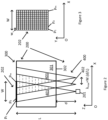
- Figure 2 schematically represents an example inspection system 200 for inspecting cargo 300 according to the disclosure.
- the inspection system 200 comprises a radiation source 201 configured to emit a plurality N of successive pulses 400 irradiating the cargo 300 at a frequency f.
- the inspection system 200 also comprises a matrix detector 202 comprising a first column p 1 of detectors and at least one second column p 2 of detectors.
- Inspection of the cargo 300 by the inspection system 200 involves scanning the cargo 300.
- the scanning comprises displacing the cargo 300 and the system 200 with a relative scanning displacement along a scanning direction (OX).
- OX scanning direction
- the cargo 300 is shown static with respect to the ground and the system 200 is shown as moving to the right of the figure along the direction (OX), for three pulses 400 (referred to as pulses 401, 402 and 403).
- pulses 401, 402 and 403 three pulses 400
- the system 200 may be static with respect to the ground and the cargo 300 may move to the left of the figure along the direction (OX) during the scan.
- the matrix detector 202 is also schematically represented in Figure 3 .
- OX scanning direction
- OY i.e. along direction
- the system 200 travels a distance ⁇ along the scanning direction (OX) between two pulses 400 emitted by the radiation source 201.
- the distance ⁇ max between two pulses may correspond to a desired case where the specific frequency of the radiation source 201 and the given relative speed are such that all of the parts of the cargo 300 are irradiated by the pulses 401, 402 and 403, and such that the parts of the cargo which are irradiated multiple times (i.e. because of the overlap of the pulses 401, 402 and 403 - see hashed areas in Figure 2 ) are substantially minimised, e.g. preferably substantially minimised to parts near the matrix detector 202.
- the distance ⁇ max by which the system 200 travels between two pulses i.e.
- the pace ⁇ min has dimensions of pulses per column, i.e. a period of time per a distance (i.e. inverse of a speed).
- the method 100 comprises obtaining, at S1, data associated with a scanning of at least one part 301 of the cargo 300 with a current frequency f n and determining, at S2, a pace ⁇ , at a predetermined instant t.
- the step S2 will be described in more detail further down in the disclosure.
- the method 100 also comprises:
- ⁇ 0 may be ⁇ min described above.
- the method 100 comprise outputting, at S5, data to cause the scanning to be performed with the updated frequency being the current frequency.
- the output data may comprise command data to trigger the radiation source 201 at the updated frequency.
- Figure 4 schematically represents a flow chart illustrating an example method S2 for determining the pace ⁇ at the predetermined instant t.
- determining at S2 the pace ⁇ at the predetermined instant t comprises:
- pace ⁇ Before describing the determining of the pace ⁇ performed at S24, examples of pace ⁇ are explained below.
- the pace ⁇ determined at S2 is associated with a number of pulses (the number not being necessary an integer) which is needed for the at least one part of the cargo 300 to apparently pass from one column p k of the matrix detector 202 to the next column p k+1 in the matrix detector 202.
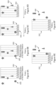
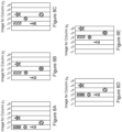
- the pace ⁇ is explained in greater detail with reference to Figures 6A to 8E .
- Other values of q ⁇ 2 may be envisaged.
- the selected number q may be such that: 2 ⁇ q ⁇ 200 .
- Figures 7A to 7F schematically represent the measurements corresponding to Figures 6A to 6C , respectively, on the matrix detector 202.
- solid objects in a column show that the corresponding objects are totally contained in the column, and hashed objects show that the corresponding objects overlap two columns.
- the hashed objects correspond to the situation where the objects appear on the two columns but with a lower contrast - for example on pulse t 1 the triangular object being between column p 1 and p 2 will generate a signal on column p 1 and p 2 .
- the image generated by column p 4 is the same image as the image generated by column p 1 with a time shift of two pulses (e.g. t 3 -t 1 ).
- the image generated by column p 5 is also the same image as the image of column p 2 with a time shift of two pulses (e.g. t 5 -t 3 ).
- the determined pace ⁇ may be compared with a predetermined pace ⁇ 0 .
- ⁇ 0 may be equal to 5, but other values are envisaged.
- the predetermined pace ⁇ 0 may be such that: L m . d ⁇ ⁇ 0 ⁇ q
- the ratio L/d takes into account the respective depth locations of the cargo and the matrix detector with respect to the radiation source. For simplicity, let the ratio L/d be equal to 1 (i.e. the cargo is located at the level of the matrix detector).
- ⁇ is smaller than 1/m, it means that an object in the cargo has moved by more than m columns in one pulse. Therefore an object in the cargo can only be seen once and only on one single image (among the m images generated by the columns), which makes any estimation of ⁇ impossible.
- the first scanning of the at least one part 301 of the cargo is performed with a current frequency f n corresponding to a nominal maximum frequency f 0 of the radiation source.
- the nominal maximum frequency f 0 may be such that: 100 Hz ⁇ f 0 ⁇ 1000 Hz
- the update at S4 does not need to be done for each pulse, because the interval between two pulses is of the order of a few milliseconds, which is too short for a truck or a train to change its speed significantly.
- the predetermined instant t at which the pace ⁇ is determined may be chosen at intervals ranging from intervals of 25ms to intervals of 500ms.
- determining at S24 the pace ⁇ may comprise :
- the image cross correlation technique may be performed on a pair of generated images.
- the pair of generated images may comprise the first image of the cargo for the first column p 1 of the matrix detector 202, and a second image of the cargo for a last column p m of the matrix detector.
- Cross-correlation of images is known to the man skilled in the art for determining a displacement field in a sequence of images.
- An example of a cross-correlation technique will now be briefly described.
- a Fourier transform may be used to find the displacement vector between the images, locally. If I p 1 and I p m are two images corresponding to columns p 1 and p m , F p 1 and F p m are the 2D Fourier transforms.
- the inverse Fourier transform of the cross power spectrum which is now a Dirac delta function localized in ( ⁇ t ) may be determined.
- Finding ( ⁇ t ) may require calculation of R, and the maximum of the Fourier transform of R may be localized.
- the above method may be applied for each pixel (x,y) on a small square window (n x n pixels) centered on the pixel, and the result may be considered as the local displacement ( ⁇ t (x,y)).
- the obtained time shift ⁇ t is divided by (p m -p 1 ) to get the pace ⁇ .
- S3 comprises determining whether the determined pace ⁇ is reliable. In some cases, especially when the m images generated using the q pulses do not exhibit a large horizontal gradient (e.g. for local homogeneous content for example), the determined pace ⁇ may not be reliable.
- S3 may also comprise determining that the pace ⁇ is reliable when C is such that: C > C min
- determining at S2 the pace ⁇ may be performed in several steps using a plurality K of instants prior to the predetermined instant t, and may comprise:
- the pace ⁇ at the predetermined instant t may thus be determined by averaging the plurality of stored paces ⁇ .
- the q pulses of an instant t may be overlapping the q pulses of an instant t-1.
- the plurality K of instants may be such that: 2 ⁇ K ⁇ 10 .
- the method 100 may further comprise performing the scanning of the cargo.
- the method may be performed while the cargo is in a predetermined scanning zone.
- Figure 9 illustrates a controller 5 configured to perform, at least partly, a method 100 according to any aspects of the disclosure.
- the controller 5 is configured to cooperate with the inspection system 200 of any aspects of the disclosure.
- the cargo 300 to be inspected is located in a container 400.
- the inspection system 200 of Figure 9 may be configured to generate the inspection data according to any aspects of the disclosure.
- the controller 5 conventionally comprises at least a processor and a memory in order to carry out an example method according to the disclosure.
- the controller 5 may comprise an interface board 51 configured to cooperate with the radiation source 201 and/or front end electronics of the matrix detector 202.
- the controller 5 may also comprise a processor 52 configured to pre-process the data associated with the scanning and/or generate the first image and the at least one second image of the present disclosure.
- the interface board 51 may be configured to, for each pulse of the plurality N of successive pulses:
- the frequency value may be sent by the processor 52 to the interface board 51 before the next acquisition of data by the front end electronics of the matrix detector 202.
- the controller 5 further comprises a memory 53 storing instructions which, when executed by the processor 52, enable the processor to perform the method according to any aspects of the disclosure.
- the processor 52 may further be configured to determine the pace ⁇ and the frequency update in real-time or near real-time (in parallel with doing the pre-processing) and to transfer the frequency update to the interface board 51.
- the processor may comprise an on-board processor located on the interface board.
- the on-board processor may comprise a field-programmable gate array, FPGA.
- the on-board processor may be configured to calculate directly the frequency update. The update of the frequency may be performed through the triggers to the radiation source without communication lag.
- the processor may have enough memory to store temporarily the required data. This architecture may be used when the relative speed of the cargo may change rapidly.
- a communication server 8 may be configured to communicate, via a communication network 7 which may be wired and/or may be wireless, with the system 200 and/or the controller 5.
- the communication server 8 may be configured to perform functions of a remote data management system.
- the server 8 may comprise a database.
- the database may be configured to store the inspection data and/or the further data of any aspects of the disclosure.
- controller 5 may be configured to store the inspection data and/or the further data of any aspects of the disclosure.
- the inspection radiation source may comprise sources of other radiation, such as, as non-limiting examples, sources of ionizing radiation, for example gamma rays or neutrons.
- a computer program, computer program product, or computer readable medium comprising computer program instructions to cause a programmable computer to carry out any one or more of the methods described herein.
- at least some portions of the activities related to the controller 5 herein may be implemented in software. It is appreciated that software components of the present disclosure may, if desired, be implemented in ROM (read only memory) form. The software components may, generally, be implemented in hardware, if desired, using conventional techniques.
- components of the controller 5 and/or the communications networks 6 and/or 7 may use specialized applications and hardware.
- the server 8 and/or the controller 5 should not be understood as a single entity, but rather refers to a physical and/or virtual device comprising at least a processor and a memory, the memory may be comprised in one or more servers which can be located in a single location or can be remote from each other to form a distributed network (such as "server farms", e.g., using wired or wireless technology).
- server farms e.g., using wired or wireless technology
- one or more memory elements can store data used for the operations described herein. This includes the memory element being able to store software, logic, code, or processor instructions that are executed to carry out the activities described in the disclosure.
- a processor can execute any type of instructions associated with the data to achieve the operations detailed herein in the disclosure.
- the processor could transform an element or an article (e.g., data) from one state or thing to another state or thing.
- the activities outlined herein may be implemented with fixed logic or programmable logic (e.g., software/computer instructions executed by a processor) and the elements identified herein could be some type of a programmable processor, programmable digital logic (e.g., a field programmable gate array (FPGA), an erasable programmable read only memory (EPROM), an electrically erasable programmable read only memory (EEPROM)), an ASIC that includes digital logic, software, code, electronic instructions, flash memory, optical disks, CD-ROMs, DVD ROMs, magnetic or optical cards, other types of machine-readable mediums suitable for storing electronic instructions, or any suitable combination thereof.
- FPGA field programmable gate array
- EPROM erasable programmable read only memory
- EEPROM electrically eras
- the communications network 6 and the communications network 7 may form only one network.
- the data received by the controller 5 may be typically received over a range of possible communications networks 6 and/or 7 at least such as: a satellite based communications network; a cable based communications network; a telephony based communications network; a mobile-telephony based communications network; an Internet Protocol (IP) communications network; and/or a computer based communications network.
- IP Internet Protocol
- the communications networks 6 and/or 7 and/or the controller 5 may comprise one or more networks.
- Networks may be provisioned in any form including, but not limited to, local area networks (LANs), wireless local area networks (WLANs), virtual local area networks (VLANs), metropolitan area networks (MANs), wide area networks (WANs), virtual private networks (VPNs), Intranet, Extranet, any other appropriate architecture or system, or any combination thereof that facilitates communications in a network.
- LANs local area networks
- WLANs wireless local area networks
- VLANs virtual local area networks
- MANs metropolitan area networks
- WANs wide area networks
- VPNs virtual private networks
- Intranet Extranet
- Extranet any other appropriate architecture or system, or any combination thereof that facilitates communications in a network.
- the inspection system 200 may be mobile and may be transported from a location to another location (the system may comprise an automotive vehicle). Alternatively or additionally, the inspection system may be static with respect to the ground and cannot be displaced.
- the power of the X-ray source may be e.g., between 4MeV and 10MeV, typically e.g., 9MeV, for a steel penetration capacity e.g., between 300mm to 450mm, typically e.g., 410mm (16.1in).
- the dose may be 17Gy.
- the system may comprise a motion generation device so that the system may be displaced, the container being static (this mode is sometimes referred to as a 'scanning' mode).
- the motion generation device may cause the container to be displaced, the system being static with respect to the ground.
- the throughput i.e. the number of containers and/or images by unit of time, may be of 20 to 30 images/hour.
- the system does not comprise a motion generation device and the container moves with respect to the system, the system being static with respect to the ground.
Landscapes
- Physics & Mathematics (AREA)
- Life Sciences & Earth Sciences (AREA)
- General Physics & Mathematics (AREA)
- Health & Medical Sciences (AREA)
- High Energy & Nuclear Physics (AREA)
- Analytical Chemistry (AREA)
- Chemical & Material Sciences (AREA)
- Biochemistry (AREA)
- General Health & Medical Sciences (AREA)
- Immunology (AREA)
- Pathology (AREA)
- Spectroscopy & Molecular Physics (AREA)
- Molecular Biology (AREA)
- General Life Sciences & Earth Sciences (AREA)
- Geophysics (AREA)
- Toxicology (AREA)
- Analysing Materials By The Use Of Radiation (AREA)
Applications Claiming Priority (2)
| Application Number | Priority Date | Filing Date | Title |
|---|---|---|---|
| GB2005684.2A GB2594449B (en) | 2020-04-20 | 2020-04-20 | Pulse frequency adjustment |
| PCT/GB2021/050938 WO2021214442A1 (en) | 2020-04-20 | 2021-04-19 | Pulse frequency adjustment |
Publications (3)
| Publication Number | Publication Date |
|---|---|
| EP4139719A1 EP4139719A1 (en) | 2023-03-01 |
| EP4139719B1 true EP4139719B1 (en) | 2025-07-02 |
| EP4139719C0 EP4139719C0 (en) | 2025-07-02 |
Family
ID=70860130
Family Applications (1)
| Application Number | Title | Priority Date | Filing Date |
|---|---|---|---|
| EP21722535.8A Active EP4139719B1 (en) | 2020-04-20 | 2021-04-19 | Pulse frequency adjustment for a cargo inspection system |
Country Status (6)
| Country | Link |
|---|---|
| US (1) | US12203879B2 (pl) |
| EP (1) | EP4139719B1 (pl) |
| CN (1) | CN115516340B (pl) |
| GB (1) | GB2594449B (pl) |
| PL (1) | PL4139719T3 (pl) |
| WO (1) | WO2021214442A1 (pl) |
Families Citing this family (2)
| Publication number | Priority date | Publication date | Assignee | Title |
|---|---|---|---|---|
| MY191342A (en) * | 2020-08-28 | 2022-06-17 | Billion Prima Sdn Bhd | A system and method for inspecting a cargo using multiple energy level radiation |
| CN116679269B (zh) * | 2023-08-03 | 2023-11-28 | 中国科学技术大学 | 扫频型随机辐射源q值表征方法及频率扫描间隔确定方法 |
Family Cites Families (11)
| Publication number | Priority date | Publication date | Assignee | Title |
|---|---|---|---|---|
| GB0803646D0 (en) * | 2008-02-28 | 2008-04-02 | Rapiscan Security Products Inc | Scanning systems |
| EA024045B1 (ru) * | 2010-05-05 | 2016-08-31 | Научно-Производственное Частное Унитарное Предприятие Адани | Система контроля самодвижущегося большегрузного транспортного средства |
| US9218933B2 (en) * | 2011-06-09 | 2015-12-22 | Rapidscan Systems, Inc. | Low-dose radiographic imaging system |
| WO2013082005A1 (en) | 2011-11-29 | 2013-06-06 | American Science And Engineering, Inc. | System and methods for multi-beam inspection of cargo in relative motion |
| US9274065B2 (en) * | 2012-02-08 | 2016-03-01 | Rapiscan Systems, Inc. | High-speed security inspection system |
| US10459111B2 (en) * | 2014-05-23 | 2019-10-29 | Radiabeam Technologies, Llc | System and method for adaptive X-ray cargo inspection |
| EP3078944B1 (en) * | 2015-04-07 | 2020-02-19 | Mettler-Toledo, LLC | Method of determining the mass of objects from a plurality of x-ray images taken at different energy level |
| CN106249307B (zh) * | 2016-07-22 | 2018-12-28 | 同方威视技术股份有限公司 | 安全检查方法和系统 |
| GB2552538B (en) * | 2016-07-28 | 2020-12-30 | Smiths Heimann Sas | Inspection system with a matrix and method |
| CN106383132B (zh) * | 2016-10-17 | 2019-05-14 | 北京君和信达科技有限公司 | 辐射检查系统和方法 |
| GB2592607B (en) | 2020-03-03 | 2024-06-19 | Smiths Detection France S A S | Resolution improvement in dual energy |
-
2020
- 2020-04-20 GB GB2005684.2A patent/GB2594449B/en active Active
-
2021
- 2021-04-19 PL PL21722535.8T patent/PL4139719T3/pl unknown
- 2021-04-19 CN CN202180029775.XA patent/CN115516340B/zh active Active
- 2021-04-19 EP EP21722535.8A patent/EP4139719B1/en active Active
- 2021-04-19 US US17/996,596 patent/US12203879B2/en active Active
- 2021-04-19 WO PCT/GB2021/050938 patent/WO2021214442A1/en not_active Ceased
Also Published As
| Publication number | Publication date |
|---|---|
| US20230221266A1 (en) | 2023-07-13 |
| CN115516340A (zh) | 2022-12-23 |
| EP4139719C0 (en) | 2025-07-02 |
| EP4139719A1 (en) | 2023-03-01 |
| WO2021214442A1 (en) | 2021-10-28 |
| US12203879B2 (en) | 2025-01-21 |
| GB2594449B (en) | 2023-07-19 |
| GB2594449A (en) | 2021-11-03 |
| CN115516340B (zh) | 2025-11-11 |
| PL4139719T3 (pl) | 2025-12-08 |
| GB202005684D0 (en) | 2020-06-03 |
Similar Documents
| Publication | Publication Date | Title |
|---|---|---|
| EP3353739B1 (en) | Denoising and/or zooming of inspection images | |
| EP4139719B1 (en) | Pulse frequency adjustment for a cargo inspection system | |
| EP2567267B1 (en) | Cargo and vehicle inspection system | |
| US10634810B2 (en) | Scanning imaging system for security inspection of an object and imaging method thereof | |
| US12467887B2 (en) | Systems and methods for eliminating cross-talk signals in one or more scanning systems having multiple X-ray sources | |
| US11536871B2 (en) | Vehicle inspection controlled using image information | |
| EP4115384B1 (en) | Resolution improvement in dual energy | |
| EP3861525B1 (en) | Correction of images | |
| EP4150568A1 (en) | Detection of liquid | |
| GB2642692A (en) | Depth information in inspection images |
Legal Events
| Date | Code | Title | Description |
|---|---|---|---|
| STAA | Information on the status of an ep patent application or granted ep patent |
Free format text: STATUS: UNKNOWN |
|
| STAA | Information on the status of an ep patent application or granted ep patent |
Free format text: STATUS: THE INTERNATIONAL PUBLICATION HAS BEEN MADE |
|
| PUAI | Public reference made under article 153(3) epc to a published international application that has entered the european phase |
Free format text: ORIGINAL CODE: 0009012 |
|
| STAA | Information on the status of an ep patent application or granted ep patent |
Free format text: STATUS: REQUEST FOR EXAMINATION WAS MADE |
|
| 17P | Request for examination filed |
Effective date: 20221031 |
|
| AK | Designated contracting states |
Kind code of ref document: A1 Designated state(s): AL AT BE BG CH CY CZ DE DK EE ES FI FR GB GR HR HU IE IS IT LI LT LU LV MC MK MT NL NO PL PT RO RS SE SI SK SM TR |
|
| DAV | Request for validation of the european patent (deleted) | ||
| DAX | Request for extension of the european patent (deleted) | ||
| GRAP | Despatch of communication of intention to grant a patent |
Free format text: ORIGINAL CODE: EPIDOSNIGR1 |
|
| STAA | Information on the status of an ep patent application or granted ep patent |
Free format text: STATUS: GRANT OF PATENT IS INTENDED |
|
| INTG | Intention to grant announced |
Effective date: 20250122 |
|
| GRAS | Grant fee paid |
Free format text: ORIGINAL CODE: EPIDOSNIGR3 |
|
| GRAA | (expected) grant |
Free format text: ORIGINAL CODE: 0009210 |
|
| STAA | Information on the status of an ep patent application or granted ep patent |
Free format text: STATUS: THE PATENT HAS BEEN GRANTED |
|
| RBV | Designated contracting states (corrected) |
Designated state(s): AL AT BE BG CH CY CZ DE DK EE ES FI FR GR HR HU IE IS IT LI LT LU LV MC MK MT NL NO PL PT RO RS SE SI SK SM TR |
|
| AK | Designated contracting states |
Kind code of ref document: B1 Designated state(s): AL AT BE BG CH CY CZ DE DK EE ES FI FR GR HR HU IE IS IT LI LT LU LV MC MK MT NL NO PL PT RO RS SE SI SK SM TR |
|
| REG | Reference to a national code |
Ref country code: CH Ref legal event code: EP |
|
| REG | Reference to a national code |
Ref country code: DE Ref legal event code: R096 Ref document number: 602021033321 Country of ref document: DE |
|
| REG | Reference to a national code |
Ref country code: IE Ref legal event code: FG4D |
|
| U01 | Request for unitary effect filed |
Effective date: 20250730 |
|
| U07 | Unitary effect registered |
Designated state(s): AT BE BG DE DK EE FI FR IT LT LU LV MT NL PT RO SE SI Effective date: 20250908 |
|
| PG25 | Lapsed in a contracting state [announced via postgrant information from national office to epo] |
Ref country code: IS Free format text: LAPSE BECAUSE OF FAILURE TO SUBMIT A TRANSLATION OF THE DESCRIPTION OR TO PAY THE FEE WITHIN THE PRESCRIBED TIME-LIMIT Effective date: 20251102 |
|
| PG25 | Lapsed in a contracting state [announced via postgrant information from national office to epo] |
Ref country code: NO Free format text: LAPSE BECAUSE OF FAILURE TO SUBMIT A TRANSLATION OF THE DESCRIPTION OR TO PAY THE FEE WITHIN THE PRESCRIBED TIME-LIMIT Effective date: 20251002 |
|
| PG25 | Lapsed in a contracting state [announced via postgrant information from national office to epo] |
Ref country code: HR Free format text: LAPSE BECAUSE OF FAILURE TO SUBMIT A TRANSLATION OF THE DESCRIPTION OR TO PAY THE FEE WITHIN THE PRESCRIBED TIME-LIMIT Effective date: 20250702 |
|
| PG25 | Lapsed in a contracting state [announced via postgrant information from national office to epo] |
Ref country code: GR Free format text: LAPSE BECAUSE OF FAILURE TO SUBMIT A TRANSLATION OF THE DESCRIPTION OR TO PAY THE FEE WITHIN THE PRESCRIBED TIME-LIMIT Effective date: 20251003 |
|
| PG25 | Lapsed in a contracting state [announced via postgrant information from national office to epo] |
Ref country code: CZ Free format text: LAPSE BECAUSE OF FAILURE TO SUBMIT A TRANSLATION OF THE DESCRIPTION OR TO PAY THE FEE WITHIN THE PRESCRIBED TIME-LIMIT Effective date: 20250702 |
|
| PG25 | Lapsed in a contracting state [announced via postgrant information from national office to epo] |
Ref country code: RS Free format text: LAPSE BECAUSE OF FAILURE TO SUBMIT A TRANSLATION OF THE DESCRIPTION OR TO PAY THE FEE WITHIN THE PRESCRIBED TIME-LIMIT Effective date: 20251002 |
|
| PG25 | Lapsed in a contracting state [announced via postgrant information from national office to epo] |
Ref country code: ES Free format text: LAPSE BECAUSE OF FAILURE TO SUBMIT A TRANSLATION OF THE DESCRIPTION OR TO PAY THE FEE WITHIN THE PRESCRIBED TIME-LIMIT Effective date: 20250702 |
|
| PG25 | Lapsed in a contracting state [announced via postgrant information from national office to epo] |
Ref country code: SM Free format text: LAPSE BECAUSE OF FAILURE TO SUBMIT A TRANSLATION OF THE DESCRIPTION OR TO PAY THE FEE WITHIN THE PRESCRIBED TIME-LIMIT Effective date: 20250702 |
|
| U20 | Renewal fee for the european patent with unitary effect paid |
Year of fee payment: 6 Effective date: 20260310 |
|
| PGFP | Annual fee paid to national office [announced via postgrant information from national office to epo] |
Ref country code: PL Payment date: 20260316 Year of fee payment: 6 |
|
| PG25 | Lapsed in a contracting state [announced via postgrant information from national office to epo] |
Ref country code: SK Free format text: LAPSE BECAUSE OF FAILURE TO SUBMIT A TRANSLATION OF THE DESCRIPTION OR TO PAY THE FEE WITHIN THE PRESCRIBED TIME-LIMIT Effective date: 20250702 |