EP4139552B1 - Bohrer - Google Patents
Bohrer Download PDFInfo
- Publication number
- EP4139552B1 EP4139552B1 EP21720555.8A EP21720555A EP4139552B1 EP 4139552 B1 EP4139552 B1 EP 4139552B1 EP 21720555 A EP21720555 A EP 21720555A EP 4139552 B1 EP4139552 B1 EP 4139552B1
- Authority
- EP
- European Patent Office
- Prior art keywords
- drill
- wedge
- drill bit
- cam
- members
- Prior art date
- Legal status (The legal status is an assumption and is not a legal conclusion. Google has not performed a legal analysis and makes no representation as to the accuracy of the status listed.)
- Active
Links
Images


Classifications
-
- E—FIXED CONSTRUCTIONS
- E21—EARTH OR ROCK DRILLING; MINING
- E21B—EARTH OR ROCK DRILLING; OBTAINING OIL, GAS, WATER, SOLUBLE OR MELTABLE MATERIALS OR A SLURRY OF MINERALS FROM WELLS
- E21B1/00—Percussion drilling
- E21B1/12—Percussion drilling with a reciprocating impulse member
- E21B1/14—Percussion drilling with a reciprocating impulse member driven by a rotating mechanism
-
- E—FIXED CONSTRUCTIONS
- E21—EARTH OR ROCK DRILLING; MINING
- E21B—EARTH OR ROCK DRILLING; OBTAINING OIL, GAS, WATER, SOLUBLE OR MELTABLE MATERIALS OR A SLURRY OF MINERALS FROM WELLS
- E21B10/00—Drill bits
- E21B10/36—Percussion drill bits
-
- E—FIXED CONSTRUCTIONS
- E21—EARTH OR ROCK DRILLING; MINING
- E21B—EARTH OR ROCK DRILLING; OBTAINING OIL, GAS, WATER, SOLUBLE OR MELTABLE MATERIALS OR A SLURRY OF MINERALS FROM WELLS
- E21B15/00—Supports for the drilling machine, e.g. derricks or masts
- E21B15/04—Supports for the drilling machine, e.g. derricks or masts specially adapted for directional drilling, e.g. slant hole rigs
-
- E—FIXED CONSTRUCTIONS
- E21—EARTH OR ROCK DRILLING; MINING
- E21B—EARTH OR ROCK DRILLING; OBTAINING OIL, GAS, WATER, SOLUBLE OR MELTABLE MATERIALS OR A SLURRY OF MINERALS FROM WELLS
- E21B49/00—Testing the nature of borehole walls; Formation testing; Methods or apparatus for obtaining samples of soil or well fluids, specially adapted to earth drilling or wells
- E21B49/02—Testing the nature of borehole walls; Formation testing; Methods or apparatus for obtaining samples of soil or well fluids, specially adapted to earth drilling or wells by mechanically taking samples of the soil
Definitions
- the present disclosure relates to a drill and a method of using a drill.
- Rotary drilling typically requires a large overhead fo rce to push the drill into a substrate.
- Percussive drilling usually requires a lower overhead force to operate, but its penetration rate in rocks is often poor, and may only be effective at shallow depths.
- Rotary-percussive drills are able to use the rotary technique to drill significant depths, with the addition of percussive shocks reducing the overhead requirement, though they can be heavy, complex systems. There remains a need for developments in this field.
- US 2,124,414 discloses a rotary drill bit of generally tapered and spear-like form, comprising a body member rotatable about a major axis coinciding with the axis of the drill stem to which the bit is applied, the tip of the bit coinciding with the major axis, and a multiplicity of hole-forming roller elements rotatable on said body member about axes alternately oppositely offset laterally from and inclined downwardly convergent towards the major axis of said body member, said roller elements tapering downwardly and the lowermost element terminating with an apex coincident, with the major axis of the body member.
- a drill comprising: a drill bit comprising a first drill part and a second drill part configuredto slide relative to each other, whereinthe first and second drill parts are pivotally coupled at one end to a first member and a second member respectively; a cam engaged with the first member and the second member, wherein the first and second members act as followers to slide the parts of the drill bit in a reciprocating motion with respect to each other, between a retracted and an extended position; and a wedge comprising a first angled surface engaged with the first member and a second angled surface engaged with the second member, the wedge configuredto urge the drill bit to pivot in a first direction when the first member is moved towards the retracted position and to pivot in a second direction when the second member is moved towards the retracted position.
- the cam may be a cylindrical cam and the first and second members may extend on opposite sides of the cylindrical cam to transform rotational movement of the cylindrical cam to a linear reciprocating motion of the first and second members.
- the drill may further comprise a motor to actuate both the reciprocating and pivot motions.
- the first and second angled surfaces of the wedge may be a pair of surfaces having the same angle of incline, such that, in use, an angle through which the drill bit pivots in the first direction may be the same as an angle through which the drill bit pivots in the second direction.
- the first member may comprise a hinge joint to pivotally couple to the first drill part and the second member may comprise a hinge joint to pivotally couple to the second drill part.
- the hinge joint may comprise rounded contact points that engage each angled surface of the wedge.
- the drill may further comprise a biasing means acting on the first and the second member to urge the first and the second members towards engagement with the angled surfaces of the wedge.
- the first drill part may be coupled to the second drill part by an interlocking connection that may prevent lateral movement or rotation of the first drill part relative to the second drill part.
- One of the first drill part and the second drill part may comprise a pin and the other of the first drill part and the second drill part may comprise a track, wherein the pin may be configured to travel within the track.
- the drill may further comprise a chamber for the ingress of material to be sampled.
- the drill may further comprise an openable cover to open and close the chamber.
- the chamber may be provided at a location between the wedge and the cam, wherein the wedge may be closer to the drill bit than the cam.
- the drill may further comprise a guide member for engagement with the first member and the second member.
- the guide member may comprise slots, and the first member and the second member may be configured to slide within said slots to guide the reciprocation motion.
- the guide member may be a sleeve disposed within an outer shell of the drill.
- the drill may comprise a sealed housing to encapsulate the first and second members, the wedge and the cam, which may protect them from external environmental conditions.
- a method of using the drill comprising: rotating the cam engaged with the first member and the second member, wherein the first and second members act as followers to slide the parts of the drill bit in a reciprocating motion with respect to each other, between a retracted and an extended position; and sliding one part of the drill bit into the retracted position, wherein the wedge urges the drill bit to pivot in a first direction as the first member is moved towards the retracted position and/or sliding the other part of the drill bit into the retracted position, wherein the wedge urges the drill bit to pivot in a second direction as the second member is moved towards the retracted position.
- Rotary drills are commonly used in terrestrial applications, however the large masses needed to provide the overhead force necessary to push the drill into the substrate make them less suitable for planetary exploration.
- both the stringent mass constraints imposed upon a mission and low gravity on some other bodies such as the Moon and Mars may make at least some rotary drills unsuitable for such applications.
- Percussive drilling involves vibrating the drill bit. Whilst percussive drilling typically requires a lower overhead mass to operate, its penetration rate in rocks is often poor, and may only be effective at relatively shallow depths. Rotary-percussive drills are able to use the rotary technique to drill significant depths, with the addition of percussive shocks reducing the overhead requirement. Despite being heavy, complex systems, they have been used on several space missions.
- substrate, material, rock, medium and drilling medium are generally interchangeable and refer to a medium through which a drill is operating a drilling action.
- drilling action generally refers to an operation of a drill in a medium, for example to form a bore in the medium.
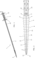
- a drill 1 according to a first embodiment is described herein with reference to Figures 1 to 7 .
- FIG. 1 shows a drill 1 for providing reciprocation and oscillation motion.
- the drill 1 comprises a drill bit 2, an actuation mechanism 3 and a stem 4 extending between the drill bit 2 and the actuation mechanism 3.
- the drill comprises a housing 43 including a cylindrical hollow outer shell of the stem 4 and a casing 51 of the actuation mechanism 3.
- FIG. 2 shows the drill bit 2 in more detail.
- the drill bit 2 comprises a first drill part 7 and a second drill part 8, herein referred to as a first part 7 and a second part 8 for ease of description.
- the first part 7 comprises one half of the drill bit 2
- the second part 8 comprises a second half of the drill bit 2.
- the drill bit 2 comprises a tip 10 at its distal end, and a base 5 at its proximal end.
- proximal is intended to mean a direction away from the tip 10 of the drill bit 2.
- distal is intended to mean a direction towards the tip 10 of the drill bit.
- the first part 7 comprises a first mating face 11 and a first external face 12, the second part 8 comprises a second mating face 13 and a second external face 14.
- the first part 7 is configured to engage the second part 8 at their respective mating faces 11, 13, via an interlocking connection 15 (shown and further described in reference to FIG. 3 ), such that the first part 7 is configured to slide relative to the second part 8.
- the mating faces 11, 13 are substantially flat surfaces, such that when the mating surfaces11, 13 are engaged, there is negligible space between them. This tends to prevent any material from being caught between the mating faces 11, 13 which may affect the sliding motion of the first and second parts 7, 8.
- the first part 7 is pivotally coupled at its base 5 to a first member 22 by a hinge joint or oscillating rod 6, and the second part 8 is pivotally coupled at its base 5 to a second member 23 by a hinge joint or oscillating rod 6.
- the first and second members 22, 23, extend linearly through the stem 4, away from the drill bit 2 to the actuation mechanism 3.
- the first and second members 22, 23 are moved by the actuation mechanism 3 (described in more detail below with reference to FIG. 4 ) in a reciprocating motion, to slide the first part 7 and the second part 8 of the drill bit 2 relative to each other.
- Each of the first part 7 and the second part 8 further comprises a plurality of teeth 9 on the external face 12, 14.
- the teeth 9 of the first part 7 are substantially symmetrical to the teeth 9 of the second part 8.
- the teeth 9 extend away from the tip 10 of the drill bit, in a proximal direction, and are spaced along a length of the first part 7 and the second part 8.
- the teeth 9 reduce in pitch size towards the tip 10.
- the teeth 9 are configured to engage a surrounding substrate during a drilling action.
- the teeth 9 can be customised for the particular medium to be drilled.
- FIG. 3 shows a more detailed view of the interlocking connection 15 that seeks to prevent lateral movement or rotation of the first part 7 relative to the second part 8.
- One of the first part 7 and the second part 8 comprises a pin 16, and the other of the first part 7 and the second part 8 comprises a slot or track 17.
- the first mating face 11 comprises the track 17
- the second mating face 13 comprises the pin 16.
- the pin 16 engages the track 17 and is moveable between a distal position where the pin is 16 is located in a first end 18 of the track 17, to a proximal position where the pin 16 is located in a second end 19 of the track 17.
- the pin 16 comprises a head 20 and a neck 21, wherein the neck 21 extends between the head 20 and the mating face 13.
- the head 20 has a larger cross sectional area than the neck 21 and the track 17 has a shape complimentary to the head 20 of the pin 16 that narrows around the neck 21, such that the head 20 can be fully retained within the track 17.
- the first part 7 is therefore able to slide with respect to the second part 8, but is prevented from separating from the second part 8.
- the head 20 and track 17 are rounded in shape, substantially spherical.
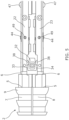
- FIG. 4 shows the actuation mechanism 3 of the drill 1 in more detail.
- the actuation mechanism 3 comprises a cylindrical cam 24 engaged with the first and second members 22, 23, and a motor 25 to actuate both the reciprocating and oscillation motion of the drill 1. Rotational movement of the motor 25 is transformed into reciprocation motion of the first and second members 22, 23 by the cam 24, wherein the first and second members 22, 23 act as dual followers.
- the proximal end of the first member 22 comprises a first follower portion 26 and the proximal end of the second member 23 comprises a second follower portion 27.
- the follower portions 26, 27 are each angled away from a central axis 28 of the drill 1, to extend on opposite sides of the cam 24.
- the follower portions, 26, 27 comprise at least one follower protrusion 29, which engages with a groove 30 of the cam 24.
- both follower portions 26, 27 are moved forwards in a distal direction and backwards in a proximal direction, with an amplitude that is a function of the slope of the groove 30 of the cam 24.
- the reciprocating movement of the first and second follower portions 26, 27 provides linear reciprocating movement to the first and second parts 7, 8 of the drill bit 2 respectively. Where the first part 7 or the second part 8 of the drill bit 2 is in its proximal most position, this is the retracted position. Where the first part 7 or the second part 8 is in the retracted position, the other of the first part 7 or the second part 8 is in its distal most position, the extended position. Therefore, the reciprocating movement of the first and second follower portions 26, 27 provides linear reciprocating movement to the first and second parts 7, 8 between a retracted position and an extended position. This is described in more detail with reference to FIG. 6a to FIG 6d .
- the actuation mechanism 3 is located away from the medium to be drilled, at a proximal end of the drill 1, to avoid any particles or dust created from the drilling action, or present in the medium, from affecting the actuation mechanism 3, particularly the motor 25.
- FIG. 5 shows a wedge 32 of the drill 1, for providing oscillation movement to the drill bit 2 of the drill 1.
- the wedge 32 is disposed close to the base 5 of the drill bit 2 and between the first member 22 and the second member 23.
- the wedge 32 comprises a first angled surface 33 engaged with the first member 22 and a second angled surface 34 engaged with the second member 23.
- the wedge 32 is configured to urge the drill bit 2 to pivot in a first direction when the first member 22 is moved towards the retracted position and to pivot in a second direction when the second member 23 is moved towards the retracted position (as shown in FIG. 6a to FIG. 6d ). This movement can be referred to as an oscillation or vibration motion.
- the oscillating rods 6 of the first and second members 22, 23 engage the wedge 32.
- the oscillating rods 6 comprise contact points 38, in the form of protrusions or pins, which engage and slide along the angled surfaces 33, 34.
- the first and second members 22, 23 pivot about the oscillating rods 6.
- the first angled surface 33 is symmetrical to the second angled surface 34.
- the first and second angled surfaces 33, 34 of the wedge 32 are a pair of surfaces having the same angle of incline, such that, in use, an angle through which the drill bit 2 pivots in the first direction is the same as an angle through which the drill bit 2 pivots in the second direction.
- the drill 1, further comprises a biasing means 44, for example but not limited to a torsional spring or elastic member, acting on the first and the second members 22, 23 to urge the first and the second members 22, 23 towards engagement with the angled surfaces 33, 34 of the wedge 32.
- a biasing means 44 for example but not limited to a torsional spring or elastic member, acting on the first and the second members 22, 23 to urge the first and the second members 22, 23 towards engagement with the angled surfaces 33, 34 of the wedge 32.
- the oscillating rods 6 pivot about the hinge axis 49.
- the biasing means 44 is a torsional spring the torsional spring axis is at the same point as the hinge axis 49.
- the first and second members 22, 23 also comprise supports 47 which are configured to contact and slide along an inner surface 48 of the outer shell of the stem 4.
- the supports 47 improve the reciprocation motion of the first and second members 22, 23 within the stem 4.
- the supports 47 may be for example but not limited to pins, protrusions or bearings.
- FIG. 6a to 6d shows the reciprocation and oscillation motion of the drill bit 2 as the drill 1 is operating.
- FIG. 6a shows the drill bit 2 in a neutral position.
- the neutral position is where neither the first part 7 nor the second part 8 is in the retracted or extended position.
- the contact points 38 of the first and second members 22, 23 are at the same position along the angled surfaces 33, 34 of the wedge 32, and therefore the drill bit 2 is not rotated towards a first direction or a second direction.
- the tip 10 and the base 5 of each of the first part 7 and the second part 8 are aligned.
- FIG. 6b shows the drill bit pivoted in a first direction.
- the first follower 26 moves the first part 7 from the neutral position shown in FIG. 6a , towards the retracted position and the second follower 27 moves the second part 8 towards the extended position.
- the contact point 38 of the first member 22 is moved along the first angled surface 33, towards a proximal end of the wedge 32.
- the contact point 38 of the second member 23 is moved along the second angled surface 34 towards a distal end of the wedge 32.
- the oscillating rods 6 are rotated with respect to the first and second members 22, 23, to pivot or swing the drill bit 2 in the first direction.
- FIG. 6c shows the drill bit 2 back in the neutral position.
- the first follower 26 moves the first part 7 from the retracted position shown in FIG. 6b , distally towards the neutral position and the second follower 27 moves the second part 8 proximally towards the neutral position.
- the contact points 38 of the first and second members 22, 23 are at the same position along the angled surfaces 33, 34 of the wedge 32, and therefore the drill bit 2 is not rotated towards a first direction or a second direction.
- the tip 10 and the base 5 of each of the first part 7 and the second part 8 are again aligned.
- FIG. 6d shows the drill bit pivoted in a second direction.
- the first follower 26 moves the first part 7 from the neutral position shown in FIG. 6c , towards the extended position and the second follower 27 moves the second part 8 towards the retracted position.
- the contact point 38 of the first member 22 is moved along the first angled surface 33, towards a distal end of the wedge 32.
- the contact point 38 of the second member 23 is moved along the second angled surface 34 towards a proximal end of the wedge 32.
- the oscillating rods 6 are rotated with respect to the first and second members 22, 23, to pivot or swing the drill bit 2 in the second direction, opposite to the first direction.
- the first follower 26 moves the first part 7 from the extended position shown in FIG. 6d , proximally towards the neutral position of FIG. 6a and the second follower 27 moves the second part 8 distally towards the neutral position of FIG. 6a .
- the oscillation cycle can then be repeated.
- the teeth 9 engage with the surrounding substrate, creating a traction force that is then transferred to a penetration force in the second part 8 that is moving distally.
- the ability to self-generate a penetration force greatly reduces the need for additional masses to create an overhead force, thus presenting a compact and lightweight drilling solution.
- Advantageously integrating the oscillation or vibration movement of the drill bit 2 swinging in a first and second direction with the reciprocation motion of the first and second members 22, 23 seeks to improve the drilling performance. Combining the oscillation motion with the reciprocation motion can enhance the penetration rate and reduce the drilling time and power of the drill 1.
- the drill 1 includes a sampling chamber 39 and an openable cover 35 (or openable shutter) to open and close the sampling chamber 39 for the ingress of material to be sampled. More particularly, the openable cover 35 opens and closes an aperture 52 in the stem 4 which provides access to the sampling chamber 39.
- the sampling chamber 39 is provided in the stem 4 at a location between the wedge 32 and the cam 24, wherein the wedge 32 is closer to the drill bit 2 than the cam 24.
- the drill 1 also comprises an access cover 46, to enable access to sampling chamber 39 to retrieve the sample.
- the openable cover 35 is opened and closed by a latch which is moved by a linear actuator 37 (shown in FIG. 4 ) provided in the drill 1.
- the linear actuator 37 is located at a proximal end of the drill 1, such that it is located away from the medium to be drilled to avoid any particles or dust from the medium from affecting or damaging the linear actuator 37.
- the proximal and distal end of the sampling chamber 39 is sealed with a sealing member 45.
- the sealing member 45 aims to retain the sample within the sampling chamber 39.
- the sealing member 45 may be, for example but not limited to, a rubber bung or alternative polymer component.
- the openable cover 35 of the sampling chamber 39 may be opened for the ingress of material to be sampled at predefined depth, after penetrating the medium.
- the sampling chamber 39 has a length much greater than its width or diameter such that it provides enough space for the samples, but remains within the limits of the stem 4. This way the sampling chamber 39 does not cause a protuberance in the stem 4, which could impede the drilling action of the drill 1.
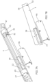
- FIG. 7B shows how the sampling chamber 39, openable cover 35 and access cover 46 are positioned in the hollow cylindrical outer shell of the stem 4.
- the access cover 46 is openable by screws which are fixed in place during a drilling operation, alternatively opening the access cover 46 may be automated or latched.
- the drill 1 comprises a guide member 40 surrounding the first and second members 22, 23.
- the guide member is a sleeve 40.
- the guide member 40 comprises slots 50 for receiving the first and second members 22, 23.
- the guide member 40 is fixed within the outer shell of the stem 4.
- the first and second members 22, 23 are configured to slide within the slots 50 of the guide member 40, which guides the reciprocation motion of the members 22, 23. This enables an optimised reciprocation motion and therefore enhances the efficiency of the system by reducing power losses in operating the drill.
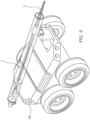
- the drill 1 can be mounted on, or integrated with, a vehicle.
- a vehicle can be a rover 36 for driving over rough extra-terrestrial terrain by remote control.
- the drill 1 is lightweight and can be launched in a compacted form and then deployed on the extra-terrestrial terrain when needed for use. Due to the lightweight and compact nature of the drill 1, the rover 36 can be equipped with more than one drill 1. This will maximise the amount of samples which can be acquired in the duration of a space mission.
- FIG. 10 is a flowchart of a method, indicated generally by the reference numeral 45, in accordance with an example embodiment.
- the method 45 shows how the drill 1 according to any embodiment described herein, may be used.
- the method 45 starts at operation 46, where the cam 24 engaged with the first member 22 and the second member 23 is rotated, wherein the first and second members 22, 23 act as followers to slide the parts 7, 8 of the drill bit 2 in a reciprocating motion with respect to each other, between a retracted and an extended position.
- one part of the drill bit 2 is slid into the retracted position, wherein the wedge 32 urges the drill bit 2 to pivot in a first direction as the first member 22 is moved towards the retracted position and/or the other part of the drill bit 2 is slid into the retracted position, wherein the wedge 32 urges the drill bit 2 to pivot in a second direction as the second member 23 is moved towards the retracted position.
- the drill 1 is sealed and entirely encapsulated to protect it from external environmental conditions. In some embodiments it is the housing 43 which is entirely encapsulated. This is particularly relevant when the drill 1 is to be used in a location comprising tough environmental conditions, for example but not limited to, in space and in harsh weather conditions. The drill 1 may also be water tight for drilling in an underwater environment.
- the drill 1 provides a practical and durable design, having fewer moving parts than at least some prior art solutions. Having fewer moving parts can mean that the drill is less vulnerable to jamming and/or breakage.
- the drill 1 is also simpler to manufacture and assemble.
- a single motor may be used for both the reciprocation and oscillation motions described above.
- the drill 1 is compact and portable for attachment to other devices, or for use in many different locations.
- the drill 1 is simple to deploy for use and stow when not in use.
- the drill 1 is also designed such that it can be used in harsh environmental conditions.
- the drill 1 can be customised and optimised based on the desired application to provide different reciprocation and oscillation amplitudes just by changing the slope angle of the cylindrical cam grooves and the slope of the wedge angled surfaces, respectively.
- the drill 1 is also scalable. It can be envisaged that the drill 1 is used in a number of different applications.
- the drill 1 may be used in medical, oil and gas, space, terrestrial drilling and manufacturing applications, among others.
- the drill bit 2 comprises two halves, the first drill part 7 and the second drill part 8.
- the first drill part 7 may be of a different size and/or shape to the second drill part 8.
- the drill bit 2 comprises two parts, the first drill part 7 and the second drill part 8.
- the drill bit 2 comprises more than two parts configured to slide relative to each other.
- the drill bit 2 is removable and replaceable.
- the drill 1 may be usage with a variety of different customised drill bits 2..
- a drill bit 2 is damaged or if a different drill bit 2 is required to better suit the medium to be drilled, then the drill bit 2 can be changed.
- the teeth 9 of the first drill part 7 are substantially symmetrical to the teeth 9 of the second drill part 8.
- the teeth 9 of the first drill part 7 can be different to the teeth 9 of the second drill part 8.
- only one of the first drill part 7 and the second drill part 8 comprises teeth 9.
- first mating face 11 is configured to engage the second mating face 13 via an interlocking connection 15.
- connection means which would enable the first part 7 to slide relative to the second part 8.
- the teeth 9 are spaced along a length of the first part 7 and the second part 8.
- the teeth 9 are spaced along a portion of the first part 7 and/or the second part 8.
- first mating face 11 comprises the track 17 and the second mating face 13 comprises the pin 16.
- second mating face 13 comprises the track 17 and the first mating face 11 comprises the pin 16.
- both the first and second mating faces 11, 13 comprise both a track 17 and a pin 16.
- the head 20 and track 17 are rounded in shape.
- the head can be for example but not limited to, a cube, a disc, a cylinder, a cone or a hemisphere and fulfil the same purpose.
- the head 20 is fully retained within the track 17.
- the track 17 can merely receive and guide the pin 16 and not fully retain it.
- the pin 16 may not comprise a neck 21, the pin 16 may comprise a ridge extending along a mating face 11, 13 of the first and/or second part 7, 8, which is triangular in cross section.
- the track 17 may comprise a complimentary V-shaped notch to receive the triangular ridge. This configuration still prevents lateral movement or rotation of the first and second parts 7, 8 relative to each other.
- the first angled surface 33 is symmetrical to the second angled surface 34.
- the first angled surface 33 comprises a steeper or shallower angle of incline with respect to the central axis 28 of the drill 1, than the second angled surface 34. This is such that the drill bit 2 oscillates further in one direction than it does in the other.
- the contact points 38 of the first and second members 22, 23 are at the same position along the angled surfaces 33, 34 of the wedge 32.
- the contact points 38 may be of different sizes, and/or the angled surfaces 33, 34 may be of different slopes.
- the contact points 38 of the first and second members 22, 23 may not be at the same position along the angled surfaces 33, 34 of the wedge 32.
- the wedge 32 comprises a pair of angled surfaces.
- the drill 1 can be converted from a reciprocation and oscillation drill, to a reciprocation only mode by replacing the wedge 32 with a straight block and/or fixing the hinge joints or oscillating rod 6.
- the torsional spring axis is at the same point as the hinge axis 49.
- the hinge axis 49 and/or the torsional spring axis may be provided at an alternative location.
- the drill 1 comprises an openable cover 35 and an access cover 46.
- the openable cover 35 and the access cover 46 can be the same component.
- the guide member 40 is a sleeve to guide the first and second members 22, 23 as they reciprocate.
- the guide member may be a pin and track connection wherein at least one of the outer shell of the stem 4 and the members 22, 23 comprises a protrusion and the other of the outer shell of the stem 4 and the members 22, 23 comprises a receiving portion, such as a groove. The protrusion is guided in the receiving portion to guide the reciprocal motion of the members 22, 23.
- the guide member 40 is fixed within the outer shell of the stem 4.
- the guide member 40 may be moveable.
Landscapes
- Engineering & Computer Science (AREA)
- Life Sciences & Earth Sciences (AREA)
- Geology (AREA)
- Mining & Mineral Resources (AREA)
- Mechanical Engineering (AREA)
- Physics & Mathematics (AREA)
- Environmental & Geological Engineering (AREA)
- Fluid Mechanics (AREA)
- General Life Sciences & Earth Sciences (AREA)
- Geochemistry & Mineralogy (AREA)
- Soil Sciences (AREA)
- Processing Of Stones Or Stones Resemblance Materials (AREA)
- Earth Drilling (AREA)
Claims (15)
- Bohrer (1), umfassend:einen Bohrmeißel (2), der ein erstes Bohrerteil (7) und ein zweites Bohrerteil (8) umfasst, die dazu konfiguriert sind, sich relativ zueinander zu verschieben, wobei das erste und das zweite Bohrerteil (7, 8) an einem Ende schwenkbar mit einem ersten Element (22) beziehungsweise einem zweiten Element (23) gekoppelt sind;eine Nocke (24), die mit dem ersten Element (22) und dem zweiten Element (23) in Eingriff steht, wobei das erste und das zweite Element als Mitnehmer wirken, um die Teile des Bohrmeißels (7, 8) in einer Hin- und Herbewegung in Bezug aufeinander zwischen einer eingefahrenen und einer ausgefahrenen Position zu verschieben; undeinen Keil (32), der eine erste abgewinkelte Oberfläche (33), die mit dem ersten Element (22) in Eingriff steht, und eine zweite abgewinkelte Oberfläche (34), die mit dem zweiten Element (23) in Eingriff steht, umfasst, wobei der Keil (32) dazu konfiguriert ist, den Bohrmeißel (2) so zu drängen, dass er in eine erste Richtung schwenkt, wenn das erste Element (22) zu der eingefahrenen Position bewegt wird, und in eine zweite Richtung schwenkt, wenn das zweite Element (23) zu der eingefahrenen Position bewegt wird.
- Bohrer (1) nach Anspruch 1, wobei die Nocke (24) eine zylindrische Nocke ist und sich das erste und das zweite Element (22, 23) auf gegenüberliegenden Seiten der zylindrischen Nocke erstrecken, um eine Drehbewegung der zylindrischen Nocke (24) in eine lineare Hin- und Herbewegung des ersten und des zweiten Elements (22, 23) umzuwandeln.
- Bohrer (1) nach Anspruch 1 oder Anspruch 2, ferner einen Motor (25) umfassend, um sowohl die Hin- und Herbewegung als auch die Schwenkbewegung anzutreiben.
- Bohrer (1) nach einem der Ansprüche 1 bis 3, wobei die erste und die zweite abgewinkelte Oberfläche (33, 34) des Keils (32) ein Oberflächenpaar mit dem gleichen Neigungswinkel sind, so dass bei Verwendung ein Winkel, um den sich der Bohrmeißel (2) in die erste Richtung schwenkt, der gleich ist wie ein Winkel, um den sich der Bohrmeißel (2) in die zweite Richtung schwenkt.
- Bohrer (1) nach einem der vorhergehenden Ansprüche, wobei das erste Element (22) ein Scharniergelenk (6) zum schwenkbaren Koppeln mit dem ersten Bohrerteil (7) umfasst und das zweite Element (23) ein Scharniergelenk (6) zum schwenkbaren Koppeln mit dem zweiten Bohrerteil (8) umfasst.
- Bohrer (1) nach Anspruch 5, wobei die Scharniergelenke (6) abgerundete Kontaktpunkte (38) umfassen, die jede abgewinkelte Oberfläche (33, 34) des Keils (32) in Eingriff nehmen.
- Bohrer (1) nach einem der vorhergehenden Ansprüche, ferner ein Vorspannmittel (44) umfassend, das auf das erste (22) und das zweite Element (23) wirkt, um das erste und das zweite Element zu einem Eingriff mit den abgewinkelten Oberflächen (33,34) des Keils (32) zu drängen.
- Bohrer (1) nach einem der vorhergehenden Ansprüche, wobei das erste Bohrerteil (7) mit dem zweiten Bohrerteil (8) durch eine formschlüssige Verbindung (15) gekoppelt ist, die eine seitliche Bewegung oder Drehung des ersten Bohrerteils (7) relativ zu dem zweiten Bohrerteil (8) verhindert.
- Bohrer (1) nach Anspruch 8, wobei eines von dem ersten Bohrerteil (7) und dem zweiten Bohrerteil (8) einen Stift (16) umfasst und das andere von dem ersten Bohrerteil (7) und dem zweiten Bohrerteil (8) eine Führungsbahn (17) umfasst, wobei der Stift (16) dazu konfiguriert ist, sich innerhalb der Führungsbahn (17) zu bewegen.
- Bohrer (1) nach einem der vorhergehenden Ansprüche, ferner eine Kammer (39) für den Eintritt von zu beprobendem Material umfassend.
- Bohrer (1) nach Anspruch 10, ferner eine öffenbare Abdeckung (35) zum Öffnen und Schließen der Kammer (39) umfassend.
- Bohrer (1) nach Anspruch 10 oder Anspruch 11, wobei die Kammer (39) an einer Stelle zwischen dem Keil (32) und der Nocke (24) bereitgestellt ist, wobei der Keil (32) näher an dem Bohrmeißel (2) als die Nocke (24) liegt.
- Bohrer (1) nach einem der vorhergehenden Ansprüche, ferner ein Führungselement (40) zum Eingriff mit dem ersten Element (22) und dem zweiten Element (23) umfassend, wobei das Führungselement (40) mindestens zwei Schlitze (50) umfasst und das erste Element (22) und das zweite Element (23) dazu konfiguriert sind, sich in den Schlitzen (50) zu verschieben, um die Hin- und Herbewegung zu führen.
- Bohrer (1) nach einem der vorhergehenden Ansprüche, wobei der Bohrer (1) ein abgedichtetes Gehäuse umfasst, um das erste und zweite Element (22, 23), den Keil (32) und die Nocken (24) einzukapseln, um sie vor äußeren Umweltbedingungen zu schützen.
- Verfahren zum Verwenden des Bohrers (1) nach einem der vorhergehenden Ansprüche, wobei das Verfahren Folgendes umfasst:Drehen der Nocke (24), die mit dem ersten Element (22) und dem zweiten Element (23) in Eingriff steht, wobei das erste und das zweite Element (22, 23) als Mitnehmer wirken, um die Teile (7, 8) des Bohrmeißels (2) in einer Hin- und Herbewegung in Bezug aufeinander zwischen einer eingefahrenen und einer ausgefahrenen Position zu verschieben; undVerschieben eines Teils (7, 8) des Bohrmeißels (2) in die eingefahrene Position, wobei der Keil (32) den Bohrmeißel (2) drängt, in eine erste Richtung zu schwenken, während das erste Element (22) in die eingefahrene Position bewegt wird, und/oder Verschieben des anderen Teils (7, 8) des Bohrmeißel (2) in die eingefahrene Position, wobei der Keil (32) den Bohrmeißel (2) drängt, in eine zweite Richtung zu schwenken, während das zweite Element (23) in die eingefahrene Position bewegt wird.
Applications Claiming Priority (2)
| Application Number | Priority Date | Filing Date | Title |
|---|---|---|---|
| GBGB2005716.2A GB202005716D0 (en) | 2020-04-20 | 2020-04-20 | A Drill |
| PCT/GB2021/050914 WO2021214431A1 (en) | 2020-04-20 | 2021-04-16 | A drill |
Publications (3)
| Publication Number | Publication Date |
|---|---|
| EP4139552A1 EP4139552A1 (de) | 2023-03-01 |
| EP4139552C0 EP4139552C0 (de) | 2023-12-27 |
| EP4139552B1 true EP4139552B1 (de) | 2023-12-27 |
Family
ID=70860017
Family Applications (1)
| Application Number | Title | Priority Date | Filing Date |
|---|---|---|---|
| EP21720555.8A Active EP4139552B1 (de) | 2020-04-20 | 2021-04-16 | Bohrer |
Country Status (6)
| Country | Link |
|---|---|
| US (1) | US12071813B2 (de) |
| EP (1) | EP4139552B1 (de) |
| CN (1) | CN115667661A (de) |
| ES (1) | ES2971505T3 (de) |
| GB (1) | GB202005716D0 (de) |
| WO (1) | WO2021214431A1 (de) |
Family Cites Families (20)
| Publication number | Priority date | Publication date | Assignee | Title |
|---|---|---|---|---|
| US748054A (en) * | 1902-10-13 | 1903-12-29 | Edward Double | Underreamer. |
| US820101A (en) * | 1905-03-25 | 1906-05-08 | Edward Double | Underreamer. |
| US1388105A (en) * | 1919-01-24 | 1921-08-16 | Double Alice | Underreamer |
| US1656436A (en) * | 1922-01-16 | 1928-01-17 | Alfred G Heggem | Underreamer |
| US2124414A (en) | 1936-04-18 | 1938-07-19 | Otto B Goldman | Well drilling bit |
| US2620162A (en) * | 1946-11-16 | 1952-12-02 | Pennington Harry | Hammer type rotary rock-drilling bit |
| US3322216A (en) * | 1964-11-18 | 1967-05-30 | Ingersoll Rand Co | Anvil for percussive drill |
| US4852672A (en) * | 1988-08-15 | 1989-08-01 | Behrens Robert N | Drill apparatus having a primary drill and a pilot drill |
| CN2153633Y (zh) * | 1992-11-10 | 1994-01-19 | 赤峰红花沟金矿 | 地质取样机 |
| US5390749A (en) * | 1994-01-31 | 1995-02-21 | Ingersoll-Rand Company | Apparatus for positioning a split retaining ring in a down-hole percussive drill |
| AU2002220867A1 (en) * | 2000-12-09 | 2002-06-18 | Fisher Power Wave Ltd | Boring apparatus |
| US9068399B2 (en) * | 2006-10-20 | 2015-06-30 | Drillroc Pneumatic Pty Ltd | Down-the-hole hammer drill |
| IES20100666A2 (en) * | 2010-10-15 | 2011-06-22 | Minroc Techn Promotions Ltd | A down-the-hole hammer |
| CN202483446U (zh) * | 2012-03-15 | 2012-10-10 | 淮南市志君钻探机具有限责任公司 | 一种钻、扩定心组合钻头 |
| WO2016026022A1 (en) * | 2014-08-18 | 2016-02-25 | R.N.P. Industries Inc. | Improved self-supporting pneumatic hammer positioner with universal joint |
| ES2716614T3 (es) * | 2016-03-04 | 2019-06-13 | Sandvik Intellectual Property | Conjunto de retención de broca de martillo perforador en fondo |
| CN106703684B (zh) * | 2017-02-22 | 2018-08-10 | 武汉科技大学 | 一种地下钻进机器人 |
| CN106948771A (zh) * | 2017-03-09 | 2017-07-14 | 长江大学 | 一种螺旋式水力加压防制动工具 |
| FI127993B (en) * | 2017-08-31 | 2019-07-15 | Pirkan Laatupalvelu Oy | Fluid operated drilling device |
| CN209339851U (zh) * | 2018-12-26 | 2019-09-03 | 河南豫中地质勘察工程公司 | 一种取心全面钻进可变组合式钻头 |
-
2020
- 2020-04-20 GB GBGB2005716.2A patent/GB202005716D0/en not_active Ceased
-
2021
- 2021-04-16 US US17/996,782 patent/US12071813B2/en active Active
- 2021-04-16 ES ES21720555T patent/ES2971505T3/es active Active
- 2021-04-16 CN CN202180037583.3A patent/CN115667661A/zh active Pending
- 2021-04-16 WO PCT/GB2021/050914 patent/WO2021214431A1/en not_active Ceased
- 2021-04-16 EP EP21720555.8A patent/EP4139552B1/de active Active
Also Published As
| Publication number | Publication date |
|---|---|
| ES2971505T3 (es) | 2024-06-05 |
| EP4139552A1 (de) | 2023-03-01 |
| EP4139552C0 (de) | 2023-12-27 |
| US20230151693A1 (en) | 2023-05-18 |
| CN115667661A (zh) | 2023-01-31 |
| GB202005716D0 (en) | 2020-06-03 |
| WO2021214431A1 (en) | 2021-10-28 |
| US12071813B2 (en) | 2024-08-27 |
Similar Documents
| Publication | Publication Date | Title |
|---|---|---|
| US6729416B2 (en) | Method and apparatus for retaining a core sample within a coring tool | |
| EA018284B1 (ru) | Система податливо соединенных режущих/калибрующих элементов | |
| Sadeghi et al. | Robotic mechanism for soil penetration inspired by plant root | |
| US7445059B1 (en) | Drill string deflecting apparatus | |
| CA2006920C (fr) | Equipement pour garniture de forage comportant un element a actionner, un moteur et des moyens de commande | |
| EP4139552B1 (de) | Bohrer | |
| US5601152A (en) | Vibrator core drilling apparatus | |
| CN102680275A (zh) | 地外星体浅层土壤取样装置 | |
| US6550549B2 (en) | Core break-off mechanism | |
| BRPI0914014B1 (pt) | Ferramenta de fundo de poço para executar uma operação de fundo de poço e método para controlar o fluxo de fluido através de uma ferramenta de fundo de poço | |
| US4388945A (en) | Valve assembly and disassembly device | |
| US20100000794A1 (en) | Lead the Bit Rotary Steerable Tool | |
| CN110566148A (zh) | 一种钻斗和旋挖钻机 | |
| US6725932B2 (en) | Down hole jar tool | |
| US8960325B2 (en) | Free-mass and interface configurations of hammering mechanisms | |
| US20150176342A1 (en) | Mud motor drive-shaft with improved bearings | |
| US6745836B2 (en) | Down hole motor assembly and associated method for providing radial energy | |
| EP0845578A3 (de) | Schiebeseitentüranlage zur Verwendung in einem Bohrloch | |
| EP3798399A1 (de) | Scharniervorrichtung für eine drehtür | |
| US4693326A (en) | Cycloidal earth cutting system with rocker-type nutating action | |
| US5017035A (en) | Breach loading cartridge pen | |
| MX2012013122A (es) | Procedimientos para mecanizar una cara interna de una carcasa que presenta una abertura. | |
| US9033067B2 (en) | Vibrational tool with rotating engagement surfaces and method | |
| CN118815379A (zh) | 自适应复合冲击钻井装置 | |
| US2979962A (en) | Percussion attachments for rotary drills |
Legal Events
| Date | Code | Title | Description |
|---|---|---|---|
| STAA | Information on the status of an ep patent application or granted ep patent |
Free format text: STATUS: UNKNOWN |
|
| STAA | Information on the status of an ep patent application or granted ep patent |
Free format text: STATUS: THE INTERNATIONAL PUBLICATION HAS BEEN MADE |
|
| PUAI | Public reference made under article 153(3) epc to a published international application that has entered the european phase |
Free format text: ORIGINAL CODE: 0009012 |
|
| STAA | Information on the status of an ep patent application or granted ep patent |
Free format text: STATUS: REQUEST FOR EXAMINATION WAS MADE |
|
| 17P | Request for examination filed |
Effective date: 20221013 |
|
| AK | Designated contracting states |
Kind code of ref document: A1 Designated state(s): AL AT BE BG CH CY CZ DE DK EE ES FI FR GB GR HR HU IE IS IT LI LT LU LV MC MK MT NL NO PL PT RO RS SE SI SK SM TR |
|
| DAV | Request for validation of the european patent (deleted) | ||
| DAX | Request for extension of the european patent (deleted) | ||
| GRAP | Despatch of communication of intention to grant a patent |
Free format text: ORIGINAL CODE: EPIDOSNIGR1 |
|
| STAA | Information on the status of an ep patent application or granted ep patent |
Free format text: STATUS: GRANT OF PATENT IS INTENDED |
|
| INTG | Intention to grant announced |
Effective date: 20230814 |
|
| GRAS | Grant fee paid |
Free format text: ORIGINAL CODE: EPIDOSNIGR3 |
|
| GRAA | (expected) grant |
Free format text: ORIGINAL CODE: 0009210 |
|
| STAA | Information on the status of an ep patent application or granted ep patent |
Free format text: STATUS: THE PATENT HAS BEEN GRANTED |
|
| AK | Designated contracting states |
Kind code of ref document: B1 Designated state(s): AL AT BE BG CH CY CZ DE DK EE ES FI FR GB GR HR HU IE IS IT LI LT LU LV MC MK MT NL NO PL PT RO RS SE SI SK SM TR |
|
| REG | Reference to a national code |
Ref country code: GB Ref legal event code: FG4D |
|
| REG | Reference to a national code |
Ref country code: CH Ref legal event code: EP |
|
| REG | Reference to a national code |
Ref country code: DE Ref legal event code: R096 Ref document number: 602021008128 Country of ref document: DE |
|
| REG | Reference to a national code |
Ref country code: IE Ref legal event code: FG4D |
|
| U01 | Request for unitary effect filed |
Effective date: 20240119 |
|
| U07 | Unitary effect registered |
Designated state(s): AT BE BG DE DK EE FI FR IT LT LU LV MT NL PT SE SI Effective date: 20240129 |
|
| PG25 | Lapsed in a contracting state [announced via postgrant information from national office to epo] |
Ref country code: GR Free format text: LAPSE BECAUSE OF FAILURE TO SUBMIT A TRANSLATION OF THE DESCRIPTION OR TO PAY THE FEE WITHIN THE PRESCRIBED TIME-LIMIT Effective date: 20240328 |
|
| PG25 | Lapsed in a contracting state [announced via postgrant information from national office to epo] |
Ref country code: GR Free format text: LAPSE BECAUSE OF FAILURE TO SUBMIT A TRANSLATION OF THE DESCRIPTION OR TO PAY THE FEE WITHIN THE PRESCRIBED TIME-LIMIT Effective date: 20240328 |
|
| PG25 | Lapsed in a contracting state [announced via postgrant information from national office to epo] |
Ref country code: RS Free format text: LAPSE BECAUSE OF FAILURE TO SUBMIT A TRANSLATION OF THE DESCRIPTION OR TO PAY THE FEE WITHIN THE PRESCRIBED TIME-LIMIT Effective date: 20231227 Ref country code: NO Free format text: LAPSE BECAUSE OF FAILURE TO SUBMIT A TRANSLATION OF THE DESCRIPTION OR TO PAY THE FEE WITHIN THE PRESCRIBED TIME-LIMIT Effective date: 20240327 Ref country code: HR Free format text: LAPSE BECAUSE OF FAILURE TO SUBMIT A TRANSLATION OF THE DESCRIPTION OR TO PAY THE FEE WITHIN THE PRESCRIBED TIME-LIMIT Effective date: 20231227 |
|
| REG | Reference to a national code |
Ref country code: ES Ref legal event code: FG2A Ref document number: 2971505 Country of ref document: ES Kind code of ref document: T3 Effective date: 20240605 |
|
| U20 | Renewal fee for the european patent with unitary effect paid |
Year of fee payment: 4 Effective date: 20240429 |
|
| PG25 | Lapsed in a contracting state [announced via postgrant information from national office to epo] |
Ref country code: IS Free format text: LAPSE BECAUSE OF FAILURE TO SUBMIT A TRANSLATION OF THE DESCRIPTION OR TO PAY THE FEE WITHIN THE PRESCRIBED TIME-LIMIT Effective date: 20240427 |
|
| PG25 | Lapsed in a contracting state [announced via postgrant information from national office to epo] |
Ref country code: CZ Free format text: LAPSE BECAUSE OF FAILURE TO SUBMIT A TRANSLATION OF THE DESCRIPTION OR TO PAY THE FEE WITHIN THE PRESCRIBED TIME-LIMIT Effective date: 20231227 |
|
| PG25 | Lapsed in a contracting state [announced via postgrant information from national office to epo] |
Ref country code: SK Free format text: LAPSE BECAUSE OF FAILURE TO SUBMIT A TRANSLATION OF THE DESCRIPTION OR TO PAY THE FEE WITHIN THE PRESCRIBED TIME-LIMIT Effective date: 20231227 |
|
| PG25 | Lapsed in a contracting state [announced via postgrant information from national office to epo] |
Ref country code: SM Free format text: LAPSE BECAUSE OF FAILURE TO SUBMIT A TRANSLATION OF THE DESCRIPTION OR TO PAY THE FEE WITHIN THE PRESCRIBED TIME-LIMIT Effective date: 20231227 Ref country code: SK Free format text: LAPSE BECAUSE OF FAILURE TO SUBMIT A TRANSLATION OF THE DESCRIPTION OR TO PAY THE FEE WITHIN THE PRESCRIBED TIME-LIMIT Effective date: 20231227 Ref country code: RO Free format text: LAPSE BECAUSE OF FAILURE TO SUBMIT A TRANSLATION OF THE DESCRIPTION OR TO PAY THE FEE WITHIN THE PRESCRIBED TIME-LIMIT Effective date: 20231227 Ref country code: IS Free format text: LAPSE BECAUSE OF FAILURE TO SUBMIT A TRANSLATION OF THE DESCRIPTION OR TO PAY THE FEE WITHIN THE PRESCRIBED TIME-LIMIT Effective date: 20240427 Ref country code: CZ Free format text: LAPSE BECAUSE OF FAILURE TO SUBMIT A TRANSLATION OF THE DESCRIPTION OR TO PAY THE FEE WITHIN THE PRESCRIBED TIME-LIMIT Effective date: 20231227 |
|
| PG25 | Lapsed in a contracting state [announced via postgrant information from national office to epo] |
Ref country code: PL Free format text: LAPSE BECAUSE OF FAILURE TO SUBMIT A TRANSLATION OF THE DESCRIPTION OR TO PAY THE FEE WITHIN THE PRESCRIBED TIME-LIMIT Effective date: 20231227 |
|
| PG25 | Lapsed in a contracting state [announced via postgrant information from national office to epo] |
Ref country code: PL Free format text: LAPSE BECAUSE OF FAILURE TO SUBMIT A TRANSLATION OF THE DESCRIPTION OR TO PAY THE FEE WITHIN THE PRESCRIBED TIME-LIMIT Effective date: 20231227 |
|
| REG | Reference to a national code |
Ref country code: DE Ref legal event code: R097 Ref document number: 602021008128 Country of ref document: DE |
|
| PLBE | No opposition filed within time limit |
Free format text: ORIGINAL CODE: 0009261 |
|
| STAA | Information on the status of an ep patent application or granted ep patent |
Free format text: STATUS: NO OPPOSITION FILED WITHIN TIME LIMIT |
|
| PG25 | Lapsed in a contracting state [announced via postgrant information from national office to epo] |
Ref country code: MC Free format text: LAPSE BECAUSE OF FAILURE TO SUBMIT A TRANSLATION OF THE DESCRIPTION OR TO PAY THE FEE WITHIN THE PRESCRIBED TIME-LIMIT Effective date: 20231227 |
|
| PG25 | Lapsed in a contracting state [announced via postgrant information from national office to epo] |
Ref country code: MC Free format text: LAPSE BECAUSE OF FAILURE TO SUBMIT A TRANSLATION OF THE DESCRIPTION OR TO PAY THE FEE WITHIN THE PRESCRIBED TIME-LIMIT Effective date: 20231227 |
|
| REG | Reference to a national code |
Ref country code: CH Ref legal event code: PL |
|
| 26N | No opposition filed |
Effective date: 20240930 |
|
| PG25 | Lapsed in a contracting state [announced via postgrant information from national office to epo] |
Ref country code: CH Free format text: LAPSE BECAUSE OF NON-PAYMENT OF DUE FEES Effective date: 20240430 |
|
| PG25 | Lapsed in a contracting state [announced via postgrant information from national office to epo] |
Ref country code: IE Free format text: LAPSE BECAUSE OF NON-PAYMENT OF DUE FEES Effective date: 20240416 |
|
| U20 | Renewal fee for the european patent with unitary effect paid |
Year of fee payment: 5 Effective date: 20250414 |
|
| PGFP | Annual fee paid to national office [announced via postgrant information from national office to epo] |
Ref country code: GB Payment date: 20250410 Year of fee payment: 5 Ref country code: ES Payment date: 20250519 Year of fee payment: 5 |
|
| PG25 | Lapsed in a contracting state [announced via postgrant information from national office to epo] |
Ref country code: CY Free format text: LAPSE BECAUSE OF FAILURE TO SUBMIT A TRANSLATION OF THE DESCRIPTION OR TO PAY THE FEE WITHIN THE PRESCRIBED TIME-LIMIT; INVALID AB INITIO Effective date: 20210416 |
|
| PG25 | Lapsed in a contracting state [announced via postgrant information from national office to epo] |
Ref country code: HU Free format text: LAPSE BECAUSE OF FAILURE TO SUBMIT A TRANSLATION OF THE DESCRIPTION OR TO PAY THE FEE WITHIN THE PRESCRIBED TIME-LIMIT; INVALID AB INITIO Effective date: 20210416 |