EP4139227B1 - A container having a sealed compartment, packaged aerosol-generating article and method of forming the same - Google Patents
A container having a sealed compartment, packaged aerosol-generating article and method of forming the same Download PDFInfo
- Publication number
- EP4139227B1 EP4139227B1 EP21720270.4A EP21720270A EP4139227B1 EP 4139227 B1 EP4139227 B1 EP 4139227B1 EP 21720270 A EP21720270 A EP 21720270A EP 4139227 B1 EP4139227 B1 EP 4139227B1
- Authority
- EP
- European Patent Office
- Prior art keywords
- line
- weakness
- substrate layer
- container
- substrate
- Prior art date
- Legal status (The legal status is an assumption and is not a legal conclusion. Google has not performed a legal analysis and makes no representation as to the accuracy of the status listed.)
- Active
Links
Images





Classifications
-
- B—PERFORMING OPERATIONS; TRANSPORTING
- B65—CONVEYING; PACKING; STORING; HANDLING THIN OR FILAMENTARY MATERIAL
- B65D—CONTAINERS FOR STORAGE OR TRANSPORT OF ARTICLES OR MATERIALS, e.g. BAGS, BARRELS, BOTTLES, BOXES, CANS, CARTONS, CRATES, DRUMS, JARS, TANKS, HOPPERS, FORWARDING CONTAINERS; ACCESSORIES, CLOSURES, OR FITTINGS THEREFOR; PACKAGING ELEMENTS; PACKAGES
- B65D75/00—Packages comprising articles or materials partially or wholly enclosed in strips, sheets, blanks, tubes or webs of flexible sheet material, e.g. in folded wrappers
- B65D75/52—Details
- B65D75/58—Opening or contents-removing devices added or incorporated during package manufacture
- B65D75/5805—Opening or contents-removing devices added or incorporated during package manufacture for tearing a side strip parallel and next to the edge, e.g. by means of a line of weakness
-
- B—PERFORMING OPERATIONS; TRANSPORTING
- B65—CONVEYING; PACKING; STORING; HANDLING THIN OR FILAMENTARY MATERIAL
- B65D—CONTAINERS FOR STORAGE OR TRANSPORT OF ARTICLES OR MATERIALS, e.g. BAGS, BARRELS, BOTTLES, BOXES, CANS, CARTONS, CRATES, DRUMS, JARS, TANKS, HOPPERS, FORWARDING CONTAINERS; ACCESSORIES, CLOSURES, OR FITTINGS THEREFOR; PACKAGING ELEMENTS; PACKAGES
- B65D75/00—Packages comprising articles or materials partially or wholly enclosed in strips, sheets, blanks, tubes or webs of flexible sheet material, e.g. in folded wrappers
- B65D75/28—Articles or materials wholly enclosed in composite wrappers, i.e. wrappers formed by associating or interconnecting two or more sheets or blanks
- B65D75/30—Articles or materials enclosed between two opposed sheets or blanks having their margins united, e.g. by pressure-sensitive adhesive, crimping, heat-sealing, or welding
-
- B—PERFORMING OPERATIONS; TRANSPORTING
- B65—CONVEYING; PACKING; STORING; HANDLING THIN OR FILAMENTARY MATERIAL
- B65D—CONTAINERS FOR STORAGE OR TRANSPORT OF ARTICLES OR MATERIALS, e.g. BAGS, BARRELS, BOTTLES, BOXES, CANS, CARTONS, CRATES, DRUMS, JARS, TANKS, HOPPERS, FORWARDING CONTAINERS; ACCESSORIES, CLOSURES, OR FITTINGS THEREFOR; PACKAGING ELEMENTS; PACKAGES
- B65D75/00—Packages comprising articles or materials partially or wholly enclosed in strips, sheets, blanks, tubes or webs of flexible sheet material, e.g. in folded wrappers
- B65D75/26—Articles or materials wholly enclosed in laminated sheets or wrapper blanks
-
- B—PERFORMING OPERATIONS; TRANSPORTING
- B65—CONVEYING; PACKING; STORING; HANDLING THIN OR FILAMENTARY MATERIAL
- B65D—CONTAINERS FOR STORAGE OR TRANSPORT OF ARTICLES OR MATERIALS, e.g. BAGS, BARRELS, BOTTLES, BOXES, CANS, CARTONS, CRATES, DRUMS, JARS, TANKS, HOPPERS, FORWARDING CONTAINERS; ACCESSORIES, CLOSURES, OR FITTINGS THEREFOR; PACKAGING ELEMENTS; PACKAGES
- B65D75/00—Packages comprising articles or materials partially or wholly enclosed in strips, sheets, blanks, tubes or webs of flexible sheet material, e.g. in folded wrappers
- B65D75/40—Packages formed by enclosing successive articles, or increments of material, in webs, e.g. folded or tubular webs, or by subdividing tubes filled with liquid, semi-liquid, or plastic materials
- B65D75/44—Individual packages cut from webs or tubes
- B65D75/46—Individual packages cut from webs or tubes containing articles
-
- B—PERFORMING OPERATIONS; TRANSPORTING
- B65—CONVEYING; PACKING; STORING; HANDLING THIN OR FILAMENTARY MATERIAL
- B65D—CONTAINERS FOR STORAGE OR TRANSPORT OF ARTICLES OR MATERIALS, e.g. BAGS, BARRELS, BOTTLES, BOXES, CANS, CARTONS, CRATES, DRUMS, JARS, TANKS, HOPPERS, FORWARDING CONTAINERS; ACCESSORIES, CLOSURES, OR FITTINGS THEREFOR; PACKAGING ELEMENTS; PACKAGES
- B65D75/00—Packages comprising articles or materials partially or wholly enclosed in strips, sheets, blanks, tubes or webs of flexible sheet material, e.g. in folded wrappers
- B65D75/52—Details
- B65D75/58—Opening or contents-removing devices added or incorporated during package manufacture
- B65D75/5855—Peelable seals
-
- B—PERFORMING OPERATIONS; TRANSPORTING
- B65—CONVEYING; PACKING; STORING; HANDLING THIN OR FILAMENTARY MATERIAL
- B65D—CONTAINERS FOR STORAGE OR TRANSPORT OF ARTICLES OR MATERIALS, e.g. BAGS, BARRELS, BOTTLES, BOXES, CANS, CARTONS, CRATES, DRUMS, JARS, TANKS, HOPPERS, FORWARDING CONTAINERS; ACCESSORIES, CLOSURES, OR FITTINGS THEREFOR; PACKAGING ELEMENTS; PACKAGES
- B65D85/00—Containers, packaging elements or packages, specially adapted for particular articles or materials
- B65D85/07—Containers, packaging elements or packages, specially adapted for particular articles or materials for compressible or flexible articles
- B65D85/08—Containers, packaging elements or packages, specially adapted for particular articles or materials for compressible or flexible articles rod-shaped or tubular
- B65D85/10—Containers, packaging elements or packages, specially adapted for particular articles or materials for compressible or flexible articles rod-shaped or tubular for cigarettes
- B65D85/1018—Container formed by a flexible material, i.e. soft-packages
Definitions
- the present disclosure relates to a container for consumer goods, the container comprising a sealed compartment and an access region comprising an unsealed area.
- the present disclosure also relates to a method of manufacturing a packaged aerosol-generating article.
- US 3 419 137 A describes a package for sterile packaging of articles between upper and lower webs of sheet material sealed together around the enclosed articles. Unsealed ends of the upper and lower webs are provided for peeling apart the webs to make the contents available. Extensions of the unsealed ends are sealed together to keep the inner surfaces of said ends clean up to the moment of use.
- the extensions are readily removable, as by tearing, to free the ends for peeling. It is desirable to make a container that is easy to open for a consumer. However, it is also desirable to make a container that reduces the risk of the container being opened accidentally. Typically, providing a container that is difficult to open accidentally but easy to open when desired is challenging.
- a container for consumer goods comprising a first substrate layer and a second substrate layer overlying the first substrate layer.
- a first portion of the first substrate layer and a first portion of the second substrate layer form a compartment region, wherein a perimeter of the compartment region is completely sealed to form a sealed compartment for containing one or more consumer goods.
- a second portion of the first substrate layer and a second portion of the second substrate layer form an access region directly adjacent to the compartment region.
- the access region comprises an unsealed area, wherein a perimeter of the access region extends around the unsealed area.
- the first substrate layer is attached to the second substrate layer at the perimeter of the access region.
- the unsealed area is separated from the sealed compartment by the completely sealed perimeter of the compartment region.
- the container further comprises a line of weakness extending at least partially within the unsealed area of the access region.
- the line of weakness is a first line of weakness in the first substrate layer only.
- the container further comprises a second line of weakness in the second substrate layer only.
- the second line of weakness has a different shape to the first line of weakness.
- the difference in shape between the first line of weakness and the second line of weakness defines a closure tab in the second substrate layer in the unsealed area of the access region.
- the difference in shape between the first line of weakness and the second line of weakness is such that a part of the first substrate layer may be tucked underneath the closure tab to retain the first substrate layer in a closed position.
- the term “sealed” refers to a portion of the container at which the first substrate layer is secured to the second substrate layer.
- the term “completely sealed” refers to a perimeter that is sealed along 100 percent of the length of the perimeter.
- the term "directly adjacent” is used to refer to a first portion of the container being adjacent to a second portion of the container without any intervening portions of the container being positioned between the first portion and the second portion.
- the access region is directly adjacent to the compartment region.
- the perimeter of the access region may be herein referred to as the "access region perimeter”.
- the perimeter of the compartment region may be herein referred to as the "compartment region perimeter”.
- the unsealed area of the access region facilitates opening of the container by a user.
- a user may grasp the first substrate layer at the unsealed area with one hand and grasp the second substrate layer at the unsealed area with the other hand, then peel the first substrate layer away from the second substrate layer along at least part of the completely sealed compartment region perimeter.
- the attachment of the first substrate layer to the second substrate layer at the perimeter of the access region may reduce the risk of accidental opening of the container, or prevent accidental opening of the container.
- the attachment of the first substrate layer to the second substrate layer at the access region perimeter may prevent a user from separately grasping the first substrate layer and the second substrate layer at the unsealed area.
- providing a line of weakness extending at least partially within the unsealed area may facilitate a user opening the container when desired. For example, by breaking at least one of the first substrate layer and the second substrate layer along the line of weakness in the unsealed area may allow a user to separately grasp the first substrate layer and the second substrate layer at the unsealed area.
- the unsealed area may be separated from the sealed compartment by the completely sealed perimeter of the compartment region and the perimeter of the access region.
- providing the line of weakness in both the first substrate layer and the second substrate layer may facilitate breaking of both the first substrate layer and the second substrate layer in the unsealed area.
- breaking both the first substrate layer and the second substrate layer may facilitate a user separately grasping the first substrate layer and the second substrate layer at the unsealed area.
- the line of weakness may extend between a first edge of the container and a second edge of the container.
- the line of weakness extending between the first edge of the container and the second edge of the container may facilitate a user breaking at least one of the first substrate layer and the second substrate layer along the line of weakness.
- a user may tear or otherwise break at least one of the first substrate layer and the second substrate layer along the line of weakness.
- the line of weakness extending between the first edge of the container and the second edge of the container may facilitate detachment of a part of the container comprising a part of the unsealed area of the access region when the container is broken along the line of weakness.
- detaching a part of the container comprising a part of the unsealed area may facilitate a user separately grasping the first substrate layer and the second substrate layer at the remaining part of the unsealed area of the access region.
- the perimeter of the access region may comprise at least one unsealed portion, wherein the line of weakness extends across the at least one unsealed portion.
- the at least one unsealed portion may facilitate a user separately grasping the first substrate layer and the second substrate layer at the perimeter of the access region once the container has been broken along the line of weakness.
- the at least one unsealed portion may be positioned at an edge of the container.
- positioning the at least one unsealed portion at an edge of the container may facilitate a user separately grasping the first substrate layer and the second substrate layer at an edge of the container once the container has been broken along the line of weakness.
- separately grasping the first substrate layer and the second substrate layer at an edge of the container may reduce a force required to separate the first substrate layer from the second substrate layer along the sealed compartment region perimeter when opening the container.
- the at least one unsealed portion may comprise a first unsealed portion and a second unsealed portion, wherein a first end of the line of weakness extends across the first unsealed portion and wherein a second end of the line of weakness extends across the second unsealed portion.
- this configuration may further facilitate a user separately grasping the first substrate layer and the second substrate layer at the access region once the container has been broken along the line of weakness.
- the first unsealed portion, the second unsealed portion and the unsealed area of the access region may extend continuously between a first edge of the container and a second edge of the container.
- the line of weakness may extend across a part of the sealed perimeter of the compartment region.
- the line of weakness extending across part of the sealed perimeter of the compartment region may facilitate opening of the compartment region when a user breaks the container along the line of weakness.
- the line of weakness extending across part of the sealed compartment region perimeter may facilitate a user separating the first substrate layer from the second substrate layer across at least part of the sealed compartment region perimeter when opening the container.
- the line of weakness may comprise a first end extending across a first part of the sealed perimeter of the compartment region and a second end extending across a second part of the sealed perimeter of the compartment region.
- first and second ends of the line of weakness extending across first and second parts of the sealed compartment region perimeter may further facilitate opening of the compartment region when a user breaks the container along the line of weakness.
- a central portion of the line of weakness extends across part of the unsealed area of the access region.
- a user may first break the container at the central portion of the line of weakness.
- breaking the container at the central portion of the line of weakness in the unsealed area may allow a user to separately grasp the first substrate layer and the second substrate layer.
- pulling the first substrate layer away from the second substrate layer at the central portion of the line of weakness may propagate further breaking of the line of weakness simultaneously from the central portion to the first end of the line of weakness and the second end of the line of weakness.
- the line of weakness may be linear.
- the line of weakness may extend along a substantially straight line.
- a linear line of weakness may facilitate simple manufacture of the container.
- a linear line of weakness may facilitate a user tearing or otherwise breaking the container along the line of weakness.
- a linear line of weakness may be particularly advantageous in embodiments in which the line of weakness extends between a first edge of the container and a second edge of the container.
- At least a portion of the line of weakness may be curved.
- a curved line of weakness may facilitate providing part of at least one of the first substrate layer and the second substrate layer with a desired shape when the container is broken along the line of weakness.
- the perimeter of the access region may be completely sealed.
- a completely sealed access region perimeter may further reduce the risk of accidental opening of the container.
- the second line of weakness extends at least partially within the unsealed area of the access region.
- the second line of weakness extending at least partially within the unsealed area of the access region may further facilitate a user separately grasping the first substrate layer and the second substrate layer at the unsealed area when the container is broken along the first line of weakness and the second line of weakness.
- the second line of weakness may at least partially overlie the first line of weakness.
- the second line of weakness at least partially overlying the first line of weakness may facilitate a user breaking the container along both the first line of weakness and the second line of weakness at the same time.
- the second line of weakness having a different shape to the first line of weakness may result in a part of the first substrate layer having a different shape to a part of the second substrate layer when the container is broken along the first line of weakness and the second line of weakness.
- providing part of the first substrate layer with a different shape to part of the second substrate layer after the container has been broken along the first line of weakness and the second line of weakness may facilitate a user separately grasping the first substrate layer and the second substrate layer at the unsealed area.
- providing part of the first substrate layer with a different shape to part of the second substrate layer after the container has been broken along the first line of weakness and the second line of weakness may provide the container with one or more additional features or functions.
- the closure tab may facilitate reclosing of the container after the container has been broken along the first line of weakness and the second line of weakness. For example, a part of the first substrate layer may be tucked underneath the closure tab formed by the second substrate layer to retain the first substrate layer in a closed position.
- the first portion of at least one of the first substrate layer and the second substrate layer comprises a recess, wherein the recess at least partially defines the compartment for containing one or more consumer goods.
- a recess may increase the storage capacity of the compartment.
- the recess may facilitate positioning of one or more consumer goods within the compartment during manufacture of the container.
- the recess may facilitate retention of one or more consumer goods within the compartment.
- the first portion of the first substrate layer may comprise a recess and the second substrate layer may be substantially planar.
- the first portion of the second substrate layer may comprise a recess and the first substrate layer may be substantially planar.
- the first portion of the first substrate layer may comprise a first recess and the first portion of the second substrate layer may comprise a second recess overlying the first recess, wherein the first recess and the second recess together define the compartment for receiving one or more consumer goods.
- the first recess and the second recess are the same size.
- the first recess and the second recess are the same shape.
- the line of weakness may comprise at least one of a perforation line, a fold line, a creasing line and a scored line.
- the line of weakness comprises a perforation line.
- a perforation line may be easy to form during the manufacturing process of the first substrate layer, the second substrate layer, or the container.
- it may be easy for a user to break the container along a perforation line.
- a perforation line may facilitate tearing of the container along the line of weakness.
- each of the first line of weakness and the second line of weakness may comprise at least one of a perforation line, a fold line, a creasing line and a scored line.
- each of the first line of weakness and the second line of weakness comprises a perforation line.
- Each of the first substrate layer and the second substrate layer may comprise a laminate material.
- the laminate material may comprise at least one layer of paper and at least one layer of a polymeric film.
- the at least one layer of paper may be biodegradable.
- the at least one layer of a polymeric film may facilitate securing the first substrate layer to the second substrate layer at each of the first sealed region and the second sealed region.
- the at least one layer of paper forms an outer surface of each of the first substrate layer and the second substrate layer.
- the at least one layer of a polymeric film forms an inner surface of each of the first substrate layer and the second substrate layer.
- the laminate material may comprise a layer of paper, a first layer of a polymeric film underlying the layer of paper, a second layer of a polymeric film underlying the first layer of a polymeric film, and a third layer of a polymeric film underlying the second layer of a polymeric film.
- the second layer of a polymeric film may form an impermeable barrier layer.
- the first layer of a polymeric film may secure the layer of paper to the impermeable barrier layer.
- the third layer of a polymeric film may facilitate securing the first substrate layer to the second substrate layer at each of the completely sealed compartment region perimeter and the access region perimeter.
- Each of the first layer of a polymeric film and the third layer of a polymeric film may comprise polyethylene.
- the second layer of a polymeric film may comprise ethylene vinyl alcohol.
- the first substrate layer may be secured to the second substrate layer in each of the completely sealed compartment region perimeter and the access region perimeter using at least one of an adhesive and a weld.
- the first substrate layer may be secured to the second substrate layer in each of the completely sealed compartment region perimeter and the access region perimeter using a thermal weld.
- a thermal weld may be particularly advantageous in embodiments in which each of the first substrate layer and the second substrate layer comprises a laminate material comprising at least one layer of paper and at least one layer of a polymeric film.
- a packaged aerosol-generating article comprising a container according to the first aspect of the present invention, in accordance with any of the embodiments described herein.
- the packaged aerosol-generating article also comprises an aerosol-generating article sealed within the compartment.
- aerosol-generating article refers to an article comprising an aerosol-forming substrate that is capable of releasing volatile compounds that can form an aerosol. Such volatile compounds may be released by heating the aerosol-forming substrate.
- An aerosol-generating article may be disposable.
- the aerosol-generating article may be a filter cigarette or other smoking article in which an aerosol-forming substrate comprises a tobacco material that is combusted to form smoke.
- the aerosol-generating article may be an article in which a tobacco material is heated to form an aerosol, rather than combusted.
- the aerosol-generating article may be an article in which a nicotine-containing aerosol is generated from a tobacco material, tobacco extract, or other nicotine source, without combustion, and in some cases without heating, for example through a chemical reaction.
- the aerosol-generating article may be a cartridge comprising a housing and an aerosol-forming substrate positioned within the housing.
- the aerosol-forming substrate may be a liquid aerosol-forming substrate.
- the liquid aerosol-forming substrate may be a nicotine-containing liquid.
- the cartridge may be configured for coupling to an aerosol-generating device.
- aerosol-generating device refers to a device that interacts with an aerosol-generating article comprising an aerosol-forming substrate to generate an aerosol.
- At least one of the first substrate layer and the second substrate layer of a container according to the first aspect of the present invention may comprise a recess at least partially defining the compartment for receiving one or more consumer goods. Additionally, it is known more generally to package consumer goods in a container comprising a recess for receiving the consumer goods. When forming at least part of a container from a sheet material, it may be desirable to form the recess into the sheet material during manufacture of the container. However, in some cases it is difficult to form a recess of sufficient size to accommodate the consumer goods without tearing or damaging the sheet material.
- a plug assist thermoforming process comprising providing a mold and a plug, wherein the plug comprises a plug body and an elastomeric cover extending over at least a portion of the plug body.
- the plug assist thermoforming process also comprises heating a web of substrate material to form a heated web of substrate material and positioning the heated web of substrate material between the mold and the plug.
- the plug assist thermoforming process also comprises engaging the elastomeric cover of the plug with the heated web of substrate material and inserting the plug into the mold to form the heated web of substrate material to the shape of the mold.
- the plug assist thermoforming process according to the present invention may be used to form a recess in a substrate material when forming a container for consumer goods.
- the present inventors have recognised that providing an elastomeric cover extending over at least a portion of the plug body may facilitate the formation of a deeper recess without tearing or breaking the substrate material than is possible when using a conventional plug comprising only a plug body.
- the elastomeric cover may be formed from any suitable material exhibiting elastic or rubber like properties.
- the plug body may be formed from at least one metal.
- the at least one metal may comprise a metal alloy.
- the plug body may be formed from a steel.
- the plug body may be formed from a stainless steel.
- the plug body has a shape comprising one or more rounded vertices and one or more rounded edges.
- rounded vertices and rounded edges may reduce the risk of the plug tearing or breaking the substrate material.
- at least a portion of the plug body has a rounded cuboid shape.
- the step of heating a web of substrate material comprises heating the web of substrate material to a temperature of between about 65 degrees Celsius and about 95 degrees Celsius, preferably between about 65 degrees Celsius and about 75 degrees Celsius.
- the web of substrate material may comprise a laminate material.
- the laminate material may comprise at least one layer of paper and at least one layer of a polymeric film.
- the at least one layer of paper may be biodegradable.
- the at least one layer of a polymeric film may facilitate securing the web of substrate material to one or more additional materials in a subsequent manufacturing process.
- the at least one layer of a polymeric film may facilitate securing the web of substrate material to an additional polymeric material using a thermal weld.
- the step of engaging the elastomeric cover of the plug with the heated web of substrate material comprises engaging the elastomeric cover of the plug with the at least one layer of a polymeric film.
- the laminate material may comprise a layer of paper, a first layer of a polymeric film underlying the layer of paper, a second layer of a polymeric film underlying the first layer of a polymeric film, and a third layer of a polymeric film underlying the second layer of a polymeric film.
- the second layer of a polymeric film may form an impermeable barrier layer.
- the first layer of a polymeric film may secure the layer of paper to the impermeable barrier layer.
- the third layer of a polymeric film may facilitate securing the first substrate layer to the second substrate layer at each of the first sealed region and the second sealed region.
- Each of the first layer of a polymeric film and the third layer of a polymeric film may comprise polyethylene.
- the second layer of a polymeric film may comprise ethylene vinyl alcohol.
- a method of forming a packaged aerosol-generating article comprising providing a first web of substrate material, and positioning an aerosol-generating article on the first web of substrate material.
- the method also comprises providing a second web of substrate material, and positioning the second web of substrate material over the aerosol-generating article and the first web of substrate material.
- the method also comprises securing a first portion of the first web of substrate material to a first portion of the second web of substrate material to form a compartment region, wherein a perimeter of the compartment region is completely sealed to form a sealed compartment, and wherein the aerosol-generating article is contained within the sealed compartment.
- the method also comprises securing a second portion of the first web of substrate material to a second portion of the second web of substrate material to form an access region directly adjacent to the compartment region, wherein the access region comprises an unsealed area, wherein a perimeter of the access region extends around the unsealed area, wherein the first substrate layer is attached to the second substrate layer at the perimeter of the access region, and wherein the unsealed area is separated from the sealed compartment by the completely sealed perimeter of the compartment region.
- the method also comprises forming a line of weakness extending at least partially within the unsealed area of the access region.
- the line of weakness is a first line of weakness in the first substrate layer only.
- the container further comprising a second line of weakness in the second substrate layer only.
- the second line of weakness has a different shape to the first line of weakness.
- the difference in shape between the first line of weakness and the second line of weakness defines a closure tab in the second substrate layer in the unsealed area of the access region.
- the difference in shape between the first line of weakness and the second line of weakness is such that a part of the first substrate layer may be tucked underneath the closure tab to retain the first substrate layer in a closed position.
- the method also comprises cutting the first web of substrate material and the second web of substrate material to form a packaged aerosol-generating article, the packaged aerosol-generating article comprising the aerosol-generating article and a container comprising a first substrate layer, a second substrate layer, the compartment region, the access region and the line of weakness.
- the unsealed area of the access region facilitates opening of the container by a user.
- a user may grasp the first substrate layer at the unsealed area with one hand and grasp the second substrate layer at the unsealed area with the other hand, then peel the first substrate layer away from the second substrate layer along at least part of the completely sealed compartment region perimeter.
- the attachment of the first substrate layer to the second substrate layer at the perimeter of the access region may reduce the risk of accidental opening of the container, or prevent accidental opening of the container.
- the attachment of the first substrate layer to the second substrate layer at the access region perimeter may prevent a user from separately grasping the first substrate layer and the second substrate layer at the unsealed area.
- providing a line of weakness extending at least partially within the unsealed area may facilitate a user opening the container when desired. For example, by breaking at least one of the first substrate layer and the second substrate layer along the line of weakness in the unsealed area may allow a user to separately grasp the first substrate layer and the second substrate layer at the unsealed area.
- the packaged aerosol-generating article formed according to the method of the fourth aspect of the present disclosure may be a packaged aerosol-generating article according to the second aspect of the present disclosure, in accordance with any of the embodiments described herein.
- the unsealed area may be separated from the sealed compartment by the completely sealed perimeter of the compartment region and the perimeter of the access region.
- providing the line of weakness in both the first substrate layer and the second substrate layer may facilitate breaking of both the first substrate layer and the second substrate layer in the unsealed area.
- breaking both the first substrate layer and the second substrate layer may facilitate a user separately grasping the first substrate layer and the second substrate layer at the unsealed area.
- the line of weakness may extend between a first edge of the container and a second edge of the container.
- the line of weakness extending between the first edge of the container and the second edge of the container may facilitate a user breaking at least one of the first substrate layer and the second substrate layer along the line of weakness.
- a user may tear or otherwise break at least one of the first substrate layer and the second substrate layer along the line of weakness.
- the line of weakness extending between the first edge of the container and the second edge of the container may facilitate detachment of a part of the container comprising a part of the unsealed area when the container is broken along the line of weakness.
- detaching a part of the container comprising part of the unsealed area may facilitate a user separately grasping the first substrate layer and the second substrate layer at the remaining part of the unsealed area.
- the perimeter of the access region may comprise at least one unsealed portion, wherein the line of weakness extends across the at least one unsealed portion.
- the at least one unsealed portion may facilitate a user separately grasping the first substrate layer and the second substrate layer at the perimeter of the access region once the container has been broken along the line of weakness.
- the at least one unsealed portion may be positioned at an edge of the container.
- positioning the at least one unsealed portion at an edge of the container may facilitate a user separately grasping the first substrate layer and the second substrate layer at an edge of the container once the container has been broken along the line of weakness.
- separately grasping the first substrate layer and the second substrate layer at an edge of the container may reduce a force required to separate the first substrate layer from the second substrate layer along the sealed compartment region perimeter when opening the container.
- the at least one unsealed portion may comprise a first unsealed portion and a second unsealed portion, wherein a first end of the line of weakness extends across the first unsealed portion and wherein a second end of the line of weakness extends across the second unsealed portion.
- this configuration may further facilitate a user separately grasping the first substrate layer and the second substrate layer at the access region once the container has been broken along the line of weakness.
- the first unsealed portion, the second unsealed portion and the unsealed area of the access region may extend continuously between a first edge of the container and a second edge of the container.
- the line of weakness may extend across a part of the sealed perimeter of the compartment region.
- the line of weakness extending across part of the sealed perimeter of the compartment region may facilitate opening of the compartment region when a user breaks the container along the line of weakness.
- the line of weakness extending across part of the sealed compartment region perimeter may facilitate a user separating the first substrate layer from the second substrate layer across at least part of the sealed compartment region perimeter when opening the container.
- the line of weakness may comprise a first end extending across a first part of the sealed perimeter of the compartment region and a second end extending across a second part of the sealed perimeter of the compartment region.
- first and second ends of the line of weakness extending across first and second parts of the sealed compartment region perimeter may further facilitate opening of the compartment region when a user breaks the container along the line of weakness.
- a central portion of the line of weakness extends across part of the unsealed area of the access region.
- a user may first break the container at the central portion of the line of weakness.
- breaking the container at the central portion of the line of weakness in the unsealed area may allow a user to separately grasp the first substrate layer and the second substrate layer.
- pulling the first substrate layer away from the second substrate layer at the central portion of the line of weakness may propagate further breaking of the line of weakness simultaneously from the central portion to the first end of the line of weakness and the second end of the line of weakness.
- the line of weakness may be linear.
- the line of weakness may extend along a substantially straight line.
- a linear line of weakness may facilitate simple manufacture of the container.
- a linear line of weakness may facilitate a user tearing or otherwise breaking the container along the line of weakness.
- a linear line of weakness may be particularly advantageous in embodiments in which the line of weakness extends between a first edge of the container and a second edge of the container.
- At least a portion of the line of weakness may be curved.
- a curved line of weakness may facilitate providing part of at least one of the first substrate layer and the second substrate layer with a desired shape when the container is broken along the line of weakness.
- the perimeter of the access region may be completely sealed.
- a completely sealed access region perimeter may further reduce the risk of accidental opening of the container.
- the second line of weakness extends at least partially within the unsealed area of the access region.
- the second line of weakness extending at least partially within the unsealed area of the access region may further facilitate a user separately grasping the first substrate layer and the second substrate layer at the unsealed area when the container is broken along the first line of weakness and the second line of weakness.
- the second line of weakness may at least partially overlie the first line of weakness.
- the second line of weakness at least partially overlying the first line of weakness may facilitate a user breaking the container along both the first line of weakness and the second line of weakness at the same time.
- the second line of weakness may have a different shape to the first line of weakness.
- the second line of weakness having a different shape to the first line of weakness may result in a part of the first substrate layer having a different shape to a part of the second substrate layer when the container is broken along the first line of weakness and the second line of weakness.
- providing part of the first substrate layer with a different shape to part of the second substrate layer after the container has been broken along the first line of weakness and the second line of weakness may facilitate a user separately grasping the first substrate layer and the second substrate layer at the unsealed area.
- providing part of the first substrate layer with a different shape to part of the second substrate layer after the container has been broken along the first line of weakness and the second line of weakness may provide the container with one or more additional features or functions.
- the closure tab may facilitate reclosing of the container after the container has been broken along the first line of weakness and the second line of weakness. For example, a part of the first substrate layer may be tucked underneath the closure tab formed by the second substrate layer to retain the first substrate layer in a closed position.
- the method may comprise a step of forming a recess in at least one of the first portion of the first web of substrate material and the first portion of the second web of substrate material, wherein the recess at least partially defines the compartment for containing one or more consumer goods.
- a recess may increase the storage capacity of the compartment.
- the recess may facilitate positioning of one or more consumer goods within the compartment during manufacture of the container.
- the recess may facilitate retention of one or more consumer goods within the compartment.
- the first portion of the first web of substrate material may comprise a recess and the second web of substrate material may be substantially planar.
- the first portion of the second web of substrate material may comprise a recess and the first web of substrate material may be substantially planar.
- the step of forming a recess comprises forming a first recess in the first portion of the first web of substrate material and forming a second recess in the first portion of the second web of substrate material, wherein the step of positioning the second web of substrate material over the aerosol-generating article and the first web of substrate material comprises positioning the second recess over the aerosol-generating article, and wherein the first recess and the second recess together define the compartment.
- the step of forming a recess may comprise forming the recess using a plug assist thermoforming process.
- the step of forming a recess comprises forming a first recess and forming a second recess
- each of the first recess and the second recess may be formed using a plug assist thermoforming process.
- the plug assist thermoforming process may be a plug assist thermoforming process according to the third aspect of the present disclosure, in accordance with any of the embodiments described herein.
- the plug assist thermoforming process may comprise a step of forming the recess with a mold and a plug, wherein the plug comprises a plug body and an elastomeric cover extending over at least a portion of the plug body.
- the elastomeric cover may be formed from any suitable material exhibiting elastic or rubber like properties.
- the plug body may be formed from at least one metal.
- the at least one metal may comprise a metal alloy.
- the plug body may be formed from a steel.
- the plug body may be formed from a stainless steel.
- the plug body has a shape comprising one or more rounded vertices and one or more rounded edges.
- rounded vertices and rounded edges may reduce the risk of the plug tearing or breaking the substrate material.
- at least a portion of the plug body has a rounded cuboid shape.
- the plug assist thermoforming process comprises a step of heating at least one of the first web of substrate material and the second web of substrate material to a temperature of between about 65 degrees Celsius and about 95 degrees Celsius, preferably between about 65 degrees Celsius and about 75 degrees Celsius.
- the step of forming the line of weakness may comprise forming at least one of a perforation line, a fold line, a creasing line and a scored line.
- the step of forming the line of weakness comprises forming a perforation line.
- a perforation line may be easy to form during the manufacturing process.
- it may be easy for a user to break the container along a perforation line.
- a perforation line may facilitate tearing of the container along the line of weakness.
- each of the first line of weakness and the second line of weakness may comprise at least one of a perforation line, a fold line, a creasing line and a scored line.
- each of the first line of weakness and the second line of weakness comprises a perforation line.
- Each of the first web of substrate material and the second web of substrate material may comprise a laminate material.
- each of the first web of substrate material and the second web of substrate material comprises a laminate material
- each of the first substrate layer and the second substrate layer comprises the laminate material.
- the laminate material may comprise at least one layer of paper and at least one layer of a polymeric film.
- the at least one layer of paper may be biodegradable.
- the at least one layer of a polymeric film may facilitate securing the first web of substrate material to the second web of substrate material at each of the completely sealed compartment region perimeter and the access region perimeter.
- the at least one layer of paper forms an outer surface of each of the first substrate layer and the second substrate layer.
- the at least one layer of a polymeric film forms an inner surface of each of the first substrate layer and the second substrate layer.
- the laminate material may comprise a layer of paper, a first layer of a polymeric film underlying the layer of paper, a second layer of a polymeric film underlying the first layer of a polymeric film, and a third layer of a polymeric film underlying the second layer of a polymeric film.
- the second layer of a polymeric film may form an impermeable barrier layer.
- the first layer of a polymeric film may secure the layer of paper to the impermeable barrier layer.
- the third layer of a polymeric film may facilitate securing the first web of substrate material to the second web of substrate material at each of the completely sealed compartment region perimeter and the access region perimeter.
- Each of the first layer of a polymeric film and the third layer of a polymeric film may comprise polyethylene.
- the second layer of a polymeric film may comprise ethylene vinyl alcohol.
- the steps of securing the first web of substrate material to the second web of substrate material at each of the completely sealed compartment region perimeter and the access region perimeter may comprise securing the second web of substrate material to the first web of substrate material using at least one of an adhesive and a weld.
- the first web of substrate material may be secured to the second web of substrate material in each of the completely sealed compartment region perimeter and the access region perimeter using a thermal weld.
- a thermal weld may be particularly advantageous in embodiments in which each of the first web of substrate material and the second web of substrate material comprises a laminate material comprising at least one layer of paper and at least one layer of a polymeric film.
- the aerosol-generating article may be a filter cigarette or other smoking article in which an aerosol-forming substrate comprises a tobacco material that is combusted to form smoke.
- the aerosol-generating article may be an article in which a tobacco material is heated to form an aerosol, rather than combusted.
- the aerosol-generating article may be an article in which a nicotine-containing aerosol is generated from a tobacco material, tobacco extract, or other nicotine source, without combustion, and in some cases without heating, for example through a chemical reaction.
- the aerosol-generating article may be a cartridge comprising a housing and an aerosol-forming substrate positioned within the housing.
- the aerosol-forming substrate may be a liquid aerosol-forming substrate.
- the liquid aerosol-forming substrate may be a nicotine-containing liquid.
- the cartridge may be configured for coupling to an aerosol-generating device.
- the cartridge may comprise a heater arranged to heat the aerosol-forming substrate.
- the heater may be an electric heater.
- the electric heater may be arranged to receive a supply of electrical power from an aerosol-generating device when the cartridge is coupled to an aerosol-generating device.
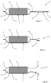
- Figures 1 to 4 show a packaged aerosol-generating article 2 according to a first embodiment of the present disclosure.
- the packaged aerosol-generating article 2 comprises a container 4 and an aerosol-generating article 6 received within the container 4.
- the container 4 comprises a first substrate layer 8 and a second substrate layer 10 overlying the first substrate layer 8.
- Each of the first substrate layer 8 and the second substrate layer 10 is formed from a laminate material comprising a layer of paper forming an outer surface of the substrate layer and a layer of a polymeric film forming an inner surface of the substrate layer.
- a first portion 3 of the first substrate layer 8 and a first portion 5 of the second substrate layer 10 form a compartment region 7, wherein a perimeter 18 of the compartment region 7 is completely sealed by a continuous thermal weld to form a sealed compartment 16 in which the aerosol-generating article 6 is positioned.
- the first portion 3 of the first substrate layer 8 comprises a first recess 12 and the first portion 5 of the second substrate layer 10 comprises a second recess 14, wherein the first recess 12 and the second recess 14 together define the compartment 16.
- a second portion 9 of the first substrate layer 8 and a second portion 11 of the second substrate layer 10 form an access region 13 directly adjacent to the compartment region 7, wherein the access region 13 comprises an unsealed area 22 and wherein a perimeter 20 of the access region 13 extends around the unsealed area 22.
- the first substrate layer 8 is attached to the second substrate layer 10 along part of the access region perimeter 20
- the access region perimeter 20 comprises two unsealed portions 15 on opposite sides of the unsealed area 22 at which the first substrate layer 8 is not attached to the second substrate layer 10.
- the unsealed area 22 is separated from the sealed compartment 16 by the completely sealed perimeter 18 of the compartment region 7.
- a line of weakness 28 comprising a perforation line is provided in the first substrate layer 8 and the second substrate layer 10, the line of weakness 28 extending between a first edge 24 of the container 4 and a second edge 26 of the container 4.
- the attachment of the first substrate layer 8 to the second substrate layer 10 along part of the length of the access region perimeter 20 makes it difficult to separate the first substrate layer 8 from the second substrate layer 10. Therefore, the attachment of the first substrate layer 8 to the second substrate layer 10 along part of the length of the access region perimeter 20 reduces the risk of the container 4 being opened accidentally.
- Opening of the container 4 to remove the aerosol-generating article 6 from the container 4 is a two-step process.
- a user tears, snaps or breaks the container 4 along the entire length of the line of weakness 28 to detach a portion of the container 4 comprising part of the access region perimeter 20.
- the outcome of this step is shown in Figure 3 .
- a user separately grasps the first substrate layer 8 and the second substrate layer 10 at the unsealed area 22 and pulls the first substrate layer 8 and the second substrate layer 10 away from each other to detach the first substrate layer 8 from the second substrate layer 10 at the sealed compartment region perimeter 18.
- This step is illustrated in Figure 4 .
- the aerosol-generating article 6 may be removed from the compartment 16.
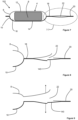
- Figures 5 to 10 show a packaged aerosol-generating article 102 according to a second embodiment of the present disclosure.
- the packaged aerosol-generating article 102 is similar to the packaged aerosol-generating article 2 described with reference to Figures 1 to 4 , and like reference numerals are used to designate like parts.
- the packaged aerosol-generating article 102 comprises a container 4 and an aerosol-generating article 6 received within the container 4.
- the container 4 comprises a first substrate layer 8 and a second substrate layer 10 overlying the first substrate layer 8.
- Each of the first substrate layer 8 and the second substrate layer 10 is formed from a laminate material comprising a layer of paper forming an outer surface of the substrate layer and a layer of a polymeric film forming an inner surface of the substrate layer.
- a first portion 3 of the first substrate layer 8 and a first portion 5 of the second substrate layer 10 form a compartment region 7, wherein a perimeter 18 of the compartment region 7 is completely sealed by a continuous thermal weld to form a sealed compartment 16 in which the aerosol-generating article 6 is positioned.
- the first portion 3 of the first substrate layer 8 comprises a first recess 12 and the first portion 5 of the second substrate layer 10 comprises a second recess 14, wherein the first recess 12 and the second recess 14 together define the compartment 16.
- a second portion 9 of the first substrate layer 8 and a second portion 11 of the second substrate layer 10 form an access region 13 directly adjacent to the compartment region 7, wherein the access region 13 comprises an unsealed area 22 and wherein a perimeter 20 of the access region 13 extends around the unsealed area 22 and is completely sealed.
- the unsealed area 22 is separated from the sealed compartment 16 by the completely sealed perimeter 18 of the compartment region 7.
- a first line of weakness 128 is provided in the first substrate layer 10 and comprises a perforation line 129 extending across part of the unsealed area 22.
- the first line of weakness 128 also comprises a first cut line 135 extending across the sealed compartment region perimeter 18 between a first end of the perforation line 129 and a first edge 24 of the container 4.
- the first line of weakness 128 also comprises a second cut line 137 extending across the sealed compartment region perimeter 18 between a second end of the perforation line 129 and a second edge 26 of the container 4.
- a second line of weakness 131 comprising a perforation line is provided in the second substrate layer 10 and extends across part of the unsealed area 22.
- the second line of weakness 131 has a different shape to the first line of weakness 128 so that the second line of weakness 131 only partially overlies the first line of weakness 128.
- end portions of the second line of weakness 131 overlie corresponding end portions of the perforation line 129 of the first line of weakness 128.
- a central portion of the second line of weakness 131 is shaped to define a tab 143. The function of the tab 143 is described in further detail below.
- the completely sealed access region perimeter 20 makes it difficult to separate the first substrate layer 8 from the second substrate layer 10. Therefore, the completely sealed access region perimeter 20 reduces the risk of the container 4 being opened accidentally.
- Opening of the container 4 to remove the aerosol-generating article 6 from the container 4 is a two-step process.
- a user bends the container 4 to break the first substrate layer 8 along the first line of weakness 128 and to break the second substrate layer 10 along the second line of weakness 131.
- the outcome of this step is shown in Figure 8 .
- a user separately grasps the first substrate layer 8 and the second substrate layer 10 at the unsealed area 22 and pulls the first substrate layer 8 and the second substrate layer 10 away from each other to detach the first substrate layer 8 from the second substrate layer 10 at the sealed compartment region perimeter 18.
- the first cut line 135 and the second cut line 137 in the first substrate layer 8 facilitate detachment of the first substrate layer 8 from the second substrate layer 10 at the sealed compartment region perimeter 18. This step is illustrated in Figure 9 .
- Figure 10 illustrates the function of the tab 143 formed by the second substrate layer 10 when the second substrate layer 10 is broken along the second line of weakness 131.
- the tab 143 facilitates reclosing of the container 4 by allowing a user to position part of the first substrate layer 8 at the unsealed area 22 under the tab 143.
- the user may reinsert the aerosol-generating article 6 into the compartment 16 and reclose the container 4 by positioning part of the first substrate layer 8 at the unsealed area 22 under the tab 143.
- the used aerosol-generating article 6 may then be carried in the container 4 until the user can dispose of the used aerosol-generating article 6 and the container 4 together.
- Figure 11 to 13 show a plug assist apparatus 200 for thermoforming a recess in a web of substrate material.
- the plug assist apparatus 200 may be used to thermoform the first recess 12 and the second recess 14 of the first substrate layer 8 and the second substrate layer 10 described with reference to Figures 1 to 10 .
- the plug assist apparatus 200 comprises a plug 202 comprising a plug body 204 formed from stainless steel and an elastomeric cover 206 extending over a portion of the plug body 204.
- the plug body 204 has a rounded cuboid shape.
- the plug assist apparatus 200 also comprises a mold 208 formed from stainless steel and positioned opposite the plug 202. Each of the plug 202 and the mold 208 is arranged for linear movement along a forming direction 210.
- the plug 202 and the mold 208 are spaced apart from each other and a web of substrate material 212 is positioned between the plug 202 and the mold 208.
- the web of substrate material is arranged for linear movement along a machine direction 214 orthogonal to the forming direction 210.
- the plug 202 and the mold 208 are advanced towards each other along the forming direction 210.
- the elastomeric cover 206 of the plug 202 engages the web of substrate material 212 and deforms the web of substrate material 212 into the mold 208.
- the plug 202 and the mold 208 are then withdrawn from the web of substrate material 212 along the forming direction 210 to leave the formed recess 216 in the web of substrate material 212.
- Figure 14 shows the steps of a plug assist thermoforming process 300 according to an embodiment of the present disclosure.
- the process of Figure 14 is described with reference to the plug assist apparatus 200 of Figures 11 to 13 , but the skilled person will appreciate that the process may be carried out using any apparatus comprising a mold and a plug comprising a plug body and an elastomeric cover.
- the plug assist thermoforming process 300 comprises providing 302 the mold 208 and the plug 202 comprising the plug body 204 and the elastomeric cover 206 extending over a portion of the plug body 204.
- the plug assist thermoforming process 300 also comprises heating 304 the web of substrate material 212.
- the heating step may be carried out by passing the web of substrate material 212 across at least one of a heated roller and a heated plate, impinging heated air or a heated gas on a surface of the web of substrate material, passing the web of substrate material through an oven, and combinations thereof.
- the plug assist thermoforming process 300 also comprises positioning 306 the heated web of substrate material 212 between the mold 208 and the plug 202.
- the heated web of substrate material 212 may be positioned between the mold 208 and the plug 202 by advancing the heated web of substrate material 212 in the machine direction 214.
- the plug assist thermoforming process 300 also comprises engaging 308 the elastomeric cover 206 of the plug 202 with the heated web of substrate material 212 and inserting 310 the plug 202 into the mold 208 to form the heated web of substrate material 212 to the shape of the mold 208.
- the plug assist thermoforming process 300 may also comprises withdrawing 312 the mold 208 and the plug 202 from the heated web of substrate material 212 and advancing the heated web of substrate material 212 to position a different portion of the heated web of substrate material 212 between the mold 208 and the plug 202.
- the steps 308, 310 and 312 may be repeated in a loop to form a series of recesses 216 in the heated web of substrate material 212.
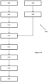
- Figure 15 shows the steps of a method 400 of forming a packaged aerosol-generating article according to an embodiment of the present disclosure.
- the packaged aerosol-generating article formed according to the method 400 may be a packaged aerosol-generating article 2 described with reference to Figures 1 to 4 , a packaged aerosol-generating article 102 described with reference to Figures 5 to 10 , or a different packaged aerosol-generating article.
- the method 400 comprises providing 402 a first web of substrate material and forming 404 a first recess in the first web of substrate material.
- the step of forming 404 a first recess in the first web of substrate material may be carried out using a plug assist thermoforming process.
- the plug assist thermoforming process may be the plug assist thermoforming process 300 described with reference to Figure 14 .
- the method 400 also comprises providing 406 a second web of substrate material and forming 408 a second recess in the second web of substrate material.
- the step of forming 408 a second recess in the second web of substrate material may be carried out using a plug assist thermoforming process.
- the plug assist thermoforming process may be the plug assist thermoforming process 300 described with reference to Figure 14 .
- the method 400 also comprises a step of positioning 410 an aerosol-generating article in the first recess of the first web of substrate material.
- the method 400 further comprises positioning 412 the second web of substrate material over the aerosol-generating article and the first web of substrate material so that the second recess of the second web of substrate material overlies the aerosol-generating article.
- the method 400 also comprises securing 414 a first portion of the first web of substrate material to a first portion of the second web of substrate material to form a compartment region, wherein a perimeter of the compartment region is completely sealed to form a sealed compartment, and wherein the aerosol-generating article is contained within the sealed compartment.
- the sealed compartment comprises the first recess and the second recess.
- the step of securing 414 the second of web of substrate material to the first web of substrate material is carried out using a thermal weld.
- the method 400 also comprises securing 416 a second portion of the first web of substrate material to a second portion of the second web of substrate material to form an access region directly adjacent to the compartment region, wherein the access region comprises an unsealed area, wherein a perimeter of the access region extends around the unsealed area, wherein the first substrate layer is attached to the second substrate layer at the perimeter of the access region, and wherein the unsealed area is separated from the sealed compartment by the completely sealed perimeter of the compartment region.
- the step of securing 416 the second of web of substrate material to the first web of substrate material is carried out using a thermal weld.
- step of securing 416 the second web of substrate material to the first web of substrate material to form the access region may be carried out before the step of securing 414 the second web of substrate material to the first web of substrate material to form the compartment region.
- step of securing 416 the second web of substrate material to the first web of substrate material to form the access region may be carried out simultaneously with the step of securing 414 the second web of substrate material to the first web of substrate material to form the compartment region.
- the method 400 also comprises forming 418 a line of weakness in at least one of the first web of substrate material and the second web of substrate material, wherein the line of weakness extends at least partially within the unsealed area of the access region.
- step of forming 418 a line of weakness may be carried out before any of the preceding steps.
- the step of forming 418 a line of weakness may comprise forming a first line of weakness in the first web of substrate material and forming a second line of weakness in the second web of substrate material.
- the method 400 may comprise separate steps of forming a first line of weakness in the first web of substrate material and forming a second line of weakness in the second web of substrate material.
- the method 400 also comprises cutting 420 the first web of substrate material and the second web of substrate material to form a packaged aerosol-generating article.
- the packaged aerosol-generating article comprises the aerosol-generating article and a container comprising a first substrate layer, a second substrate layer, the compartment region, the access region and the line of weakness.
Landscapes
- Engineering & Computer Science (AREA)
- Mechanical Engineering (AREA)
- Chemical & Material Sciences (AREA)
- Composite Materials (AREA)
- Packages (AREA)
- Cartons (AREA)
Applications Claiming Priority (2)
| Application Number | Priority Date | Filing Date | Title |
|---|---|---|---|
| EP20170731 | 2020-04-21 | ||
| PCT/EP2021/060411 WO2021214149A1 (en) | 2020-04-21 | 2021-04-21 | A container having a sealed compartment |
Publications (3)
| Publication Number | Publication Date |
|---|---|
| EP4139227A1 EP4139227A1 (en) | 2023-03-01 |
| EP4139227B1 true EP4139227B1 (en) | 2024-02-14 |
| EP4139227C0 EP4139227C0 (en) | 2024-02-14 |
Family
ID=70390936
Family Applications (1)
| Application Number | Title | Priority Date | Filing Date |
|---|---|---|---|
| EP21720270.4A Active EP4139227B1 (en) | 2020-04-21 | 2021-04-21 | A container having a sealed compartment, packaged aerosol-generating article and method of forming the same |
Country Status (7)
| Country | Link |
|---|---|
| US (1) | US12168560B2 (enExample) |
| EP (1) | EP4139227B1 (enExample) |
| JP (1) | JP7757306B2 (enExample) |
| KR (1) | KR20230002719A (enExample) |
| CN (1) | CN115443243B (enExample) |
| BR (1) | BR112022021072A2 (enExample) |
| WO (1) | WO2021214149A1 (enExample) |
Families Citing this family (3)
| Publication number | Priority date | Publication date | Assignee | Title |
|---|---|---|---|---|
| GB201812508D0 (en) * | 2018-07-31 | 2018-09-12 | Nicoventures Holdings Ltd | Aerosol generation |
| EP4351986B1 (en) * | 2021-06-09 | 2025-06-18 | Cryovac, LLC | Heat shrink apparaus and device for packaging, and packaging line and process using said heat shrink apparatus and device |
| USD1090982S1 (en) * | 2022-06-27 | 2025-08-26 | Philip Morris Products S.A. | Snus can |
Family Cites Families (18)
| Publication number | Priority date | Publication date | Assignee | Title |
|---|---|---|---|---|
| US3419137A (en) * | 1967-11-14 | 1968-12-31 | Bard Inc C R | Closed-end peel package |
| US3938659A (en) * | 1974-06-24 | 1976-02-17 | Wardwell Charles R | Frangible bonding using blush lacquer and packaging bonded therewith |
| GB2004736B (en) | 1977-09-16 | 1982-08-04 | Schur Int As Brdr | Tobacco ppuches and similar packings |
| US4266666A (en) * | 1979-12-21 | 1981-05-12 | American Can Company | Blister package |
| US5894930A (en) * | 1996-10-10 | 1999-04-20 | Mcneil-Ppc, Inc. | Directional push and peel easy to open child resistant blister package |
| US6440508B1 (en) * | 1997-11-13 | 2002-08-27 | Kyodo Shiko Co. | Laminated film, method for production thereof, bag and package using the laminated film, and method for separation thereof |
| US6726364B2 (en) * | 2002-09-19 | 2004-04-27 | Poppack, Llc | Bubble-seal apparatus for easily opening a sealed package |
| US7306371B2 (en) * | 2004-12-14 | 2007-12-11 | Poppack, Llc | Access structure with bursting detonator for opening a sealed package |
| US7607834B2 (en) * | 2004-08-02 | 2009-10-27 | R.P. Scherer Technologies, Inc. | Peelable pouch containing a single or multiple dosage forms and process of making same |
| DE102004047447B4 (de) * | 2004-09-30 | 2008-01-03 | Lts Lohmann Therapie-Systeme Ag | Peelfähige, kindesichere Verpackung für flache, biegsame Objekte, Verwendung dieser Verpackungen und Verfahren zum Verpacken von flachen, biegsamen Objekten |
| DE102004047445B4 (de) | 2004-09-30 | 2007-05-31 | Lts Lohmann Therapie-Systeme Ag | Nichtwiederverschließbare Verpackung für gesundheitsgefährdende Erzeugnisse, Verwendung der Verpackung, sowie Verfahren zu deren Herstellung |
| EP1985551A1 (en) * | 2007-04-25 | 2008-10-29 | Novartis AG | Packaging pouch |
| DE102010015618A1 (de) | 2010-04-19 | 2011-10-20 | Ebz Systec Gmbh | Fördereinrichtung für Automatisierungsstraßen |
| DE102011105014A1 (de) * | 2011-06-08 | 2012-12-13 | Focke & Co. (Gmbh & Co. Kg) | Beutel für Tabak sowie Verfahren und Vorrichtung zum Herstellen |
| CN105026283A (zh) * | 2013-01-18 | 2015-11-04 | 比密斯公司 | 用于易碎性薄材料的撕开式小袋 |
| AU2015342808A1 (en) | 2014-11-07 | 2017-05-25 | Corium, Inc. | Medical device packaging |
| US10730678B2 (en) * | 2016-05-10 | 2020-08-04 | Sonoco Development, Inc. | Mono-web package with tamper-evident tear strip and resealable flap portion |
| JP7087711B2 (ja) | 2018-06-20 | 2022-06-21 | 大日本印刷株式会社 | パウチおよびその製造方法 |
-
2021
- 2021-04-21 EP EP21720270.4A patent/EP4139227B1/en active Active
- 2021-04-21 CN CN202180028206.3A patent/CN115443243B/zh active Active
- 2021-04-21 JP JP2022562658A patent/JP7757306B2/ja active Active
- 2021-04-21 KR KR1020227039726A patent/KR20230002719A/ko active Pending
- 2021-04-21 WO PCT/EP2021/060411 patent/WO2021214149A1/en not_active Ceased
- 2021-04-21 US US17/918,756 patent/US12168560B2/en active Active
- 2021-04-21 BR BR112022021072A patent/BR112022021072A2/pt unknown
Also Published As
| Publication number | Publication date |
|---|---|
| BR112022021072A2 (pt) | 2022-12-06 |
| WO2021214149A1 (en) | 2021-10-28 |
| US20230128342A1 (en) | 2023-04-27 |
| EP4139227A1 (en) | 2023-03-01 |
| CN115443243A (zh) | 2022-12-06 |
| KR20230002719A (ko) | 2023-01-05 |
| CN115443243B (zh) | 2026-08-11 |
| US12168560B2 (en) | 2024-12-17 |
| JP7757306B2 (ja) | 2025-10-21 |
| JP2023522867A (ja) | 2023-06-01 |
| EP4139227C0 (en) | 2024-02-14 |
Similar Documents
| Publication | Publication Date | Title |
|---|---|---|
| JP7757306B2 (ja) | 封止区画を有する容器 | |
| EP2084080B1 (en) | Packaging for smoking articles | |
| TWI579209B (zh) | 菸草工業製品之捆包及包裝盒 | |
| RU2727097C2 (ru) | Повторно герметизируемая тара, содержащая язычок, который обеспечивает легкое открывание | |
| TWI602516B (zh) | 菸草工業製品之包材及其相關捆包與包裝盒 | |
| US20090158689A1 (en) | Pouch-based cumulative packaging | |
| US20190367235A1 (en) | Wrapper for Tobacco Industry Products | |
| WO2016087829A1 (en) | A wrapped bundle of tobacco industry products | |
| WO2010090932A2 (en) | Canister style package with opening feature | |
| WO2016087828A1 (en) | Wrapper for tobacco industry products | |
| CN104684818A (zh) | 密封包装 | |
| KR20180075487A (ko) | 인서트를 포함하는 재밀봉식 용기 | |
| EP4263387B1 (en) | Container having box and sleeve with anti-tamper mechanism | |
| JP2022513992A (ja) | タバコ産業製品の包装された束用の積層体 | |
| EP3571132B1 (en) | Inner frame for a pack of tobacco industry products | |
| WO2018134595A1 (en) | A wrapped bundle | |
| WO2001007336A1 (en) | Flexible bag having a tear-off band for easy opening | |
| RU2827901C1 (ru) | Тара с герметичным отделением | |
| EP3730425A1 (en) | Food dispenser | |
| CN120417796A (zh) | 包括由膜或薄片材料形成的容纳芯体的腔室的吸入装置烟弹 |
Legal Events
| Date | Code | Title | Description |
|---|---|---|---|
| STAA | Information on the status of an ep patent application or granted ep patent |
Free format text: STATUS: UNKNOWN |
|
| STAA | Information on the status of an ep patent application or granted ep patent |
Free format text: STATUS: THE INTERNATIONAL PUBLICATION HAS BEEN MADE |
|
| PUAI | Public reference made under article 153(3) epc to a published international application that has entered the european phase |
Free format text: ORIGINAL CODE: 0009012 |
|
| STAA | Information on the status of an ep patent application or granted ep patent |
Free format text: STATUS: REQUEST FOR EXAMINATION WAS MADE |
|
| 17P | Request for examination filed |
Effective date: 20221020 |
|
| AK | Designated contracting states |
Kind code of ref document: A1 Designated state(s): AL AT BE BG CH CY CZ DE DK EE ES FI FR GB GR HR HU IE IS IT LI LT LU LV MC MK MT NL NO PL PT RO RS SE SI SK SM TR |
|
| DAV | Request for validation of the european patent (deleted) | ||
| DAX | Request for extension of the european patent (deleted) | ||
| GRAP | Despatch of communication of intention to grant a patent |
Free format text: ORIGINAL CODE: EPIDOSNIGR1 |
|
| STAA | Information on the status of an ep patent application or granted ep patent |
Free format text: STATUS: GRANT OF PATENT IS INTENDED |
|
| INTG | Intention to grant announced |
Effective date: 20230907 |
|
| GRAS | Grant fee paid |
Free format text: ORIGINAL CODE: EPIDOSNIGR3 |
|
| GRAA | (expected) grant |
Free format text: ORIGINAL CODE: 0009210 |
|
| STAA | Information on the status of an ep patent application or granted ep patent |
Free format text: STATUS: THE PATENT HAS BEEN GRANTED |
|
| AK | Designated contracting states |
Kind code of ref document: B1 Designated state(s): AL AT BE BG CH CY CZ DE DK EE ES FI FR GB GR HR HU IE IS IT LI LT LU LV MC MK MT NL NO PL PT RO RS SE SI SK SM TR |
|
| REG | Reference to a national code |
Ref country code: GB Ref legal event code: FG4D |
|
| REG | Reference to a national code |
Ref country code: CH Ref legal event code: EP |
|
| REG | Reference to a national code |
Ref country code: DE Ref legal event code: R096 Ref document number: 602021009415 Country of ref document: DE |
|
| REG | Reference to a national code |
Ref country code: IE Ref legal event code: FG4D |
|
| U01 | Request for unitary effect filed |
Effective date: 20240214 |
|
| U07 | Unitary effect registered |
Designated state(s): AT BE BG DE DK EE FI FR IT LT LU LV MT NL PT SE SI Effective date: 20240222 |
|
| U20 | Renewal fee for the european patent with unitary effect paid |
Year of fee payment: 4 Effective date: 20240424 |
|
| PG25 | Lapsed in a contracting state [announced via postgrant information from national office to epo] |
Ref country code: IS Free format text: LAPSE BECAUSE OF FAILURE TO SUBMIT A TRANSLATION OF THE DESCRIPTION OR TO PAY THE FEE WITHIN THE PRESCRIBED TIME-LIMIT Effective date: 20240614 |
|
| PG25 | Lapsed in a contracting state [announced via postgrant information from national office to epo] |
Ref country code: GR Free format text: LAPSE BECAUSE OF FAILURE TO SUBMIT A TRANSLATION OF THE DESCRIPTION OR TO PAY THE FEE WITHIN THE PRESCRIBED TIME-LIMIT Effective date: 20240515 |
|
| PG25 | Lapsed in a contracting state [announced via postgrant information from national office to epo] |
Ref country code: RS Free format text: LAPSE BECAUSE OF FAILURE TO SUBMIT A TRANSLATION OF THE DESCRIPTION OR TO PAY THE FEE WITHIN THE PRESCRIBED TIME-LIMIT Effective date: 20240514 Ref country code: HR Free format text: LAPSE BECAUSE OF FAILURE TO SUBMIT A TRANSLATION OF THE DESCRIPTION OR TO PAY THE FEE WITHIN THE PRESCRIBED TIME-LIMIT Effective date: 20240214 |
|
| PG25 | Lapsed in a contracting state [announced via postgrant information from national office to epo] |
Ref country code: ES Free format text: LAPSE BECAUSE OF FAILURE TO SUBMIT A TRANSLATION OF THE DESCRIPTION OR TO PAY THE FEE WITHIN THE PRESCRIBED TIME-LIMIT Effective date: 20240214 |
|
| PG25 | Lapsed in a contracting state [announced via postgrant information from national office to epo] |
Ref country code: RS Free format text: LAPSE BECAUSE OF FAILURE TO SUBMIT A TRANSLATION OF THE DESCRIPTION OR TO PAY THE FEE WITHIN THE PRESCRIBED TIME-LIMIT Effective date: 20240514 Ref country code: NO Free format text: LAPSE BECAUSE OF FAILURE TO SUBMIT A TRANSLATION OF THE DESCRIPTION OR TO PAY THE FEE WITHIN THE PRESCRIBED TIME-LIMIT Effective date: 20240514 Ref country code: IS Free format text: LAPSE BECAUSE OF FAILURE TO SUBMIT A TRANSLATION OF THE DESCRIPTION OR TO PAY THE FEE WITHIN THE PRESCRIBED TIME-LIMIT Effective date: 20240614 Ref country code: HR Free format text: LAPSE BECAUSE OF FAILURE TO SUBMIT A TRANSLATION OF THE DESCRIPTION OR TO PAY THE FEE WITHIN THE PRESCRIBED TIME-LIMIT Effective date: 20240214 Ref country code: GR Free format text: LAPSE BECAUSE OF FAILURE TO SUBMIT A TRANSLATION OF THE DESCRIPTION OR TO PAY THE FEE WITHIN THE PRESCRIBED TIME-LIMIT Effective date: 20240515 Ref country code: ES Free format text: LAPSE BECAUSE OF FAILURE TO SUBMIT A TRANSLATION OF THE DESCRIPTION OR TO PAY THE FEE WITHIN THE PRESCRIBED TIME-LIMIT Effective date: 20240214 |
|
| PG25 | Lapsed in a contracting state [announced via postgrant information from national office to epo] |
Ref country code: PL Free format text: LAPSE BECAUSE OF FAILURE TO SUBMIT A TRANSLATION OF THE DESCRIPTION OR TO PAY THE FEE WITHIN THE PRESCRIBED TIME-LIMIT Effective date: 20240214 |
|
| U1N | Appointed representative for the unitary patent procedure changed after the registration of the unitary effect |
Representative=s name: REDDIE & GROSE LLP; GB |
|
| PG25 | Lapsed in a contracting state [announced via postgrant information from national office to epo] |
Ref country code: PL Free format text: LAPSE BECAUSE OF FAILURE TO SUBMIT A TRANSLATION OF THE DESCRIPTION OR TO PAY THE FEE WITHIN THE PRESCRIBED TIME-LIMIT Effective date: 20240214 |
|
| PG25 | Lapsed in a contracting state [announced via postgrant information from national office to epo] |
Ref country code: SM Free format text: LAPSE BECAUSE OF FAILURE TO SUBMIT A TRANSLATION OF THE DESCRIPTION OR TO PAY THE FEE WITHIN THE PRESCRIBED TIME-LIMIT Effective date: 20240214 |
|
| PG25 | Lapsed in a contracting state [announced via postgrant information from national office to epo] |
Ref country code: CZ Free format text: LAPSE BECAUSE OF FAILURE TO SUBMIT A TRANSLATION OF THE DESCRIPTION OR TO PAY THE FEE WITHIN THE PRESCRIBED TIME-LIMIT Effective date: 20240214 |
|
| PG25 | Lapsed in a contracting state [announced via postgrant information from national office to epo] |
Ref country code: SK Free format text: LAPSE BECAUSE OF FAILURE TO SUBMIT A TRANSLATION OF THE DESCRIPTION OR TO PAY THE FEE WITHIN THE PRESCRIBED TIME-LIMIT Effective date: 20240214 |
|
| PG25 | Lapsed in a contracting state [announced via postgrant information from national office to epo] |
Ref country code: SM Free format text: LAPSE BECAUSE OF FAILURE TO SUBMIT A TRANSLATION OF THE DESCRIPTION OR TO PAY THE FEE WITHIN THE PRESCRIBED TIME-LIMIT Effective date: 20240214 Ref country code: SK Free format text: LAPSE BECAUSE OF FAILURE TO SUBMIT A TRANSLATION OF THE DESCRIPTION OR TO PAY THE FEE WITHIN THE PRESCRIBED TIME-LIMIT Effective date: 20240214 Ref country code: RO Free format text: LAPSE BECAUSE OF FAILURE TO SUBMIT A TRANSLATION OF THE DESCRIPTION OR TO PAY THE FEE WITHIN THE PRESCRIBED TIME-LIMIT Effective date: 20240214 Ref country code: CZ Free format text: LAPSE BECAUSE OF FAILURE TO SUBMIT A TRANSLATION OF THE DESCRIPTION OR TO PAY THE FEE WITHIN THE PRESCRIBED TIME-LIMIT Effective date: 20240214 |
|
| REG | Reference to a national code |
Ref country code: DE Ref legal event code: R097 Ref document number: 602021009415 Country of ref document: DE |
|
| PG25 | Lapsed in a contracting state [announced via postgrant information from national office to epo] |
Ref country code: MC Free format text: LAPSE BECAUSE OF FAILURE TO SUBMIT A TRANSLATION OF THE DESCRIPTION OR TO PAY THE FEE WITHIN THE PRESCRIBED TIME-LIMIT Effective date: 20240214 |
|
| PG25 | Lapsed in a contracting state [announced via postgrant information from national office to epo] |
Ref country code: MC Free format text: LAPSE BECAUSE OF FAILURE TO SUBMIT A TRANSLATION OF THE DESCRIPTION OR TO PAY THE FEE WITHIN THE PRESCRIBED TIME-LIMIT Effective date: 20240214 |
|
| PLBE | No opposition filed within time limit |
Free format text: ORIGINAL CODE: 0009261 |
|
| STAA | Information on the status of an ep patent application or granted ep patent |
Free format text: STATUS: NO OPPOSITION FILED WITHIN TIME LIMIT |
|
| 26N | No opposition filed |
Effective date: 20241115 |
|
| PG25 | Lapsed in a contracting state [announced via postgrant information from national office to epo] |
Ref country code: IE Free format text: LAPSE BECAUSE OF NON-PAYMENT OF DUE FEES Effective date: 20240421 |
|
| U20 | Renewal fee for the european patent with unitary effect paid |
Year of fee payment: 5 Effective date: 20250425 |
|
| PG25 | Lapsed in a contracting state [announced via postgrant information from national office to epo] |
Ref country code: CY Free format text: LAPSE BECAUSE OF FAILURE TO SUBMIT A TRANSLATION OF THE DESCRIPTION OR TO PAY THE FEE WITHIN THE PRESCRIBED TIME-LIMIT; INVALID AB INITIO Effective date: 20210421 |
|
| PG25 | Lapsed in a contracting state [announced via postgrant information from national office to epo] |
Ref country code: HU Free format text: LAPSE BECAUSE OF FAILURE TO SUBMIT A TRANSLATION OF THE DESCRIPTION OR TO PAY THE FEE WITHIN THE PRESCRIBED TIME-LIMIT; INVALID AB INITIO Effective date: 20210421 |
|
| REG | Reference to a national code |
Ref country code: CH Ref legal event code: U11 Free format text: ST27 STATUS EVENT CODE: U-0-0-U10-U11 (AS PROVIDED BY THE NATIONAL OFFICE) Effective date: 20260501 |
|
| PG25 | Lapsed in a contracting state [announced via postgrant information from national office to epo] |
Ref country code: TR Free format text: LAPSE BECAUSE OF FAILURE TO SUBMIT A TRANSLATION OF THE DESCRIPTION OR TO PAY THE FEE WITHIN THE PRESCRIBED TIME-LIMIT Effective date: 20240214 |
|
| U20 | Renewal fee for the european patent with unitary effect paid |
Year of fee payment: 6 Effective date: 20260428 |
|
| PGFP | Annual fee paid to national office [announced via postgrant information from national office to epo] |
Ref country code: GB Payment date: 20260424 Year of fee payment: 6 |
|
| PGFP | Annual fee paid to national office [announced via postgrant information from national office to epo] |
Ref country code: CH Payment date: 20260501 Year of fee payment: 6 |