EP4139075B1 - System zum schutz eines bedieners eines elektrowerkzeugs - Google Patents
System zum schutz eines bedieners eines elektrowerkzeugs Download PDFInfo
- Publication number
- EP4139075B1 EP4139075B1 EP21723445.9A EP21723445A EP4139075B1 EP 4139075 B1 EP4139075 B1 EP 4139075B1 EP 21723445 A EP21723445 A EP 21723445A EP 4139075 B1 EP4139075 B1 EP 4139075B1
- Authority
- EP
- European Patent Office
- Prior art keywords
- tool
- sensors
- sensor
- distance
- power
- Prior art date
- Legal status (The legal status is an assumption and is not a legal conclusion. Google has not performed a legal analysis and makes no representation as to the accuracy of the status listed.)
- Active
Links
Images


Classifications
-
- B—PERFORMING OPERATIONS; TRANSPORTING
- B27—WORKING OR PRESERVING WOOD OR SIMILAR MATERIAL; NAILING OR STAPLING MACHINES IN GENERAL
- B27B—SAWS FOR WOOD OR SIMILAR MATERIAL; COMPONENTS OR ACCESSORIES THEREFOR
- B27B17/00—Chain saws; Equipment therefor
-
- A—HUMAN NECESSITIES
- A01—AGRICULTURE; FORESTRY; ANIMAL HUSBANDRY; HUNTING; TRAPPING; FISHING
- A01G—HORTICULTURE; CULTIVATION OF VEGETABLES, FLOWERS, RICE, FRUIT, VINES, HOPS OR SEAWEED; FORESTRY; WATERING
- A01G23/00—Forestry
- A01G23/02—Transplanting, uprooting, felling or delimbing trees
- A01G23/08—Felling trees
- A01G23/091—Sawing apparatus specially adapted for felling trees
-
- A—HUMAN NECESSITIES
- A01—AGRICULTURE; FORESTRY; ANIMAL HUSBANDRY; HUNTING; TRAPPING; FISHING
- A01G—HORTICULTURE; CULTIVATION OF VEGETABLES, FLOWERS, RICE, FRUIT, VINES, HOPS OR SEAWEED; FORESTRY; WATERING
- A01G3/00—Cutting implements specially adapted for horticultural purposes; Delimbing standing trees
- A01G3/04—Apparatus for trimming hedges, e.g. hedge shears
- A01G3/047—Apparatus for trimming hedges, e.g. hedge shears portable
- A01G3/053—Apparatus for trimming hedges, e.g. hedge shears portable motor-driven
-
- B—PERFORMING OPERATIONS; TRANSPORTING
- B23—MACHINE TOOLS; METAL-WORKING NOT OTHERWISE PROVIDED FOR
- B23D—PLANING; SLOTTING; SHEARING; BROACHING; SAWING; FILING; SCRAPING; LIKE OPERATIONS FOR WORKING METAL BY REMOVING MATERIAL, NOT OTHERWISE PROVIDED FOR
- B23D57/00—Sawing machines or sawing devices not covered by one of the preceding groups B23D45/00 - B23D55/00
- B23D57/02—Sawing machines or sawing devices not covered by one of the preceding groups B23D45/00 - B23D55/00 with chain saws
-
- B—PERFORMING OPERATIONS; TRANSPORTING
- B23—MACHINE TOOLS; METAL-WORKING NOT OTHERWISE PROVIDED FOR
- B23D—PLANING; SLOTTING; SHEARING; BROACHING; SAWING; FILING; SCRAPING; LIKE OPERATIONS FOR WORKING METAL BY REMOVING MATERIAL, NOT OTHERWISE PROVIDED FOR
- B23D57/00—Sawing machines or sawing devices not covered by one of the preceding groups B23D45/00 - B23D55/00
- B23D57/02—Sawing machines or sawing devices not covered by one of the preceding groups B23D45/00 - B23D55/00 with chain saws
- B23D57/023—Sawing machines or sawing devices not covered by one of the preceding groups B23D45/00 - B23D55/00 with chain saws hand-held or hand-operated
-
- B—PERFORMING OPERATIONS; TRANSPORTING
- B23—MACHINE TOOLS; METAL-WORKING NOT OTHERWISE PROVIDED FOR
- B23D—PLANING; SLOTTING; SHEARING; BROACHING; SAWING; FILING; SCRAPING; LIKE OPERATIONS FOR WORKING METAL BY REMOVING MATERIAL, NOT OTHERWISE PROVIDED FOR
- B23D59/00—Accessories specially designed for sawing machines or sawing devices
- B23D59/001—Measuring or control devices, e.g. for automatic control of work feed pressure on band saw blade
-
- B—PERFORMING OPERATIONS; TRANSPORTING
- B27—WORKING OR PRESERVING WOOD OR SIMILAR MATERIAL; NAILING OR STAPLING MACHINES IN GENERAL
- B27B—SAWS FOR WOOD OR SIMILAR MATERIAL; COMPONENTS OR ACCESSORIES THEREFOR
- B27B17/00—Chain saws; Equipment therefor
- B27B17/08—Drives or gearings; Devices for swivelling or tilting the chain saw
- B27B17/083—Devices for arresting movement of the saw chain
-
- F—MECHANICAL ENGINEERING; LIGHTING; HEATING; WEAPONS; BLASTING
- F16—ENGINEERING ELEMENTS AND UNITS; GENERAL MEASURES FOR PRODUCING AND MAINTAINING EFFECTIVE FUNCTIONING OF MACHINES OR INSTALLATIONS; THERMAL INSULATION IN GENERAL
- F16P—SAFETY DEVICES IN GENERAL; SAFETY DEVICES FOR PRESSES
- F16P3/00—Safety devices acting in conjunction with the control or operation of a machine; Control arrangements requiring the simultaneous use of two or more parts of the body
- F16P3/12—Safety devices acting in conjunction with the control or operation of a machine; Control arrangements requiring the simultaneous use of two or more parts of the body with means, e.g. feelers, which in case of the presence of a body part of a person in or near the danger zone influence the control or operation of the machine
-
- G—PHYSICS
- G01—MEASURING; TESTING
- G01C—MEASURING DISTANCES, LEVELS OR BEARINGS; SURVEYING; NAVIGATION; GYROSCOPIC INSTRUMENTS; PHOTOGRAMMETRY OR VIDEOGRAMMETRY
- G01C19/00—Gyroscopes; Turn-sensitive devices using vibrating masses; Turn-sensitive devices without moving masses; Measuring angular rate using gyroscopic effects
-
- G—PHYSICS
- G06—COMPUTING OR CALCULATING; COUNTING
- G06F—ELECTRIC DIGITAL DATA PROCESSING
- G06F3/00—Input arrangements for transferring data to be processed into a form capable of being handled by the computer; Output arrangements for transferring data from processing unit to output unit, e.g. interface arrangements
- G06F3/01—Input arrangements or combined input and output arrangements for interaction between user and computer
- G06F3/011—Arrangements for interaction with the human body, e.g. for user immersion in virtual reality
Definitions
- US 2010/064532 A1 discloses a chain saw 3D positional monitoring and anti-kickback actuation system that includes a signal processor receiving, generating and processing signals from multidimensional relative distances measurement modules and adjusts an electromechanical interface with the cutting device drive or power mechanism as well as actuators to counteract dangerous movements of the chainsaw.
- another system for protecting an operator of a power tool may be provided.
- the system may include a plurality of distance sensors worn by the operator, a reader disposed at the power tool, and a controller configured to determine, based on distances between each of the distance sensors and the reader, whether to initiate a protective action with respect to the power tool.
- the controller may be configured to perform an adaptive power control cycle to determine the distances between each of the distance sensors and the reader.
- yet another system for protecting an operator of a power tool may be provided.
- the system may include a plurality of inertial measurement unit (IMU)-based sensors worn by the operator, a tool position sensor disposed at the power tool, and a controller.
- the controller may be configured to determine, based on measurements between the IMU-based sensors and the tool position sensor, whether to initiate a protective action with respect to the power tool.
- the IMU-based sensors and the tool position sensor may be periodically calibrated based on predefined poses of the operator and corresponding positions of the power tool.
- Some example embodiments may improve the user experience, safety, and/or productivity during use of outdoor powered equipment.
- example embodiments may include the provision of sensor fusion with combinations of different types of sensors and tracking mechanisms.
- Example embodiments may also include the provision of tracking algorithms and/or methods that employ sensors for measuring distances accurately using adaptive signal strength measurements.
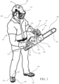
- the two sets of wearable sensors also include a second set of wearable sensors that are distance sensors 130.
- the distance sensors 130 of this example are shown to be in the same locations on the operator 110 that the IMU-based sensors 120 have been placed, such correspondence is not necessary. As such, more or fewer distance sensors 130 could be provided than IMU-based sensors 120, and the distance sensors 130 could be provided at the same or different locations on the operator 110.
- the distance sensors 130 may be configured to operate in cooperation with a tool distance sensor 132 that may be disposed at a portion of the tool (e.g., chainsaw 100).
- the IMU-based sensors 120 may be sensors configured to track movement in three dimensions.
- the distance sensors 130 may be configured to measure or track distances in either two dimensions or simply in one dimension (i.e., straight line distance). In either case, distances or proximity measurements may be performed so that the chainsaw 100 (or at least the cutting action thereof) may be disabled based on distance or proximity thresholds that can be defined (e.g., for short distances), or based on combinations of relative motion of body parts and the tool at angular velocities or linear velocities above certain thresholds (e.g., stop delay based distances for larger distances).
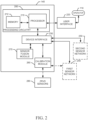
- the controller 140 may be configured to prioritize usage of one or the other of motion tracking (e.g., via the IMU-based sensors 120 and the tool position sensor 122) and distance measurement (e.g., via the distance sensors 130 and the tool distance sensor 132) in specific contexts.
- distance measurement related measures may have preference (or take precedence) within a certain range of distances (e.g., short distances), and motion tracking related measures may have preference (or take precedence) within another range of distances (e.g., at larger distances).
- the controller 140 may also be configured to manage calibration of the motion tracking functions of the IMU-based sensors 120 and the tool position sensor 122.
- the processing circuitry 200 may include one or more instances of a processor 210 and memory 212 that may be in communication with or otherwise control other components or modules that interface with the processing circuitry 200.
- the processing circuitry 200 may be embodied as a circuit chip (e.g., an integrated circuit chip) configured (e.g., with hardware, software or a combination of hardware and software) to perform operations described herein.
- the processing circuitry 200 may be embodied as a portion of an onboard computer housed in the housing 150 of the chainsaw 100 to control operation of the system relative to interaction with other motion tracking and/or distance measurement devices.
- the processor 210 may be embodied in a number of different ways.
- the processor 210 may be embodied as various processing means such as one or more of a microprocessor or other processing element, a coprocessor, a controller or various other computing or processing devices including integrated circuits such as, for example, an ASIC (application specific integrated circuit), an FPGA (field programmable gate array), or the like.
- the processor 210 may be configured to execute instructions stored in the memory 212 or otherwise accessible to the processor 210.
- Calibration functions may be performed by the calibration module 260.
- the calibration may only be applicable to the first sensor network 240 (i.e., motion tracking).
- the calibration module 260 may be configured to interface with zero relative velocity detection (ZRVD) sensors 280 (either directly or via the device interface 230) disposed on the chainsaw 100 to facilitate calibration of the motion tracking devices (i.e., the IMU-based sensors 120 and the tool position sensor 122).
- ZRVD zero relative velocity detection
- the ZRVD sensors 280 may detect that the operator 110 has maneuvered the chainsaw 100 to one of the calibration positions based on how the operator 110 is holding the chainsaw 100, and/or based on the pressing of the trigger and correlated accelerometer and/or magnetometer readings in order to determine vertical or horizontal orientation of the chainsaw 100.
- the inclusion of multiple ones of the IMU-based sensors 120 and sensors on the chainsaw 100 may ensure sufficient independence to achieve good results.
- a distance 300 from the end of the bar of the chainsaw 100 to the left glove sensor 121, which would be known to be on the front handle of the chainsaw 100 may be known.
- one or more tactile sensors 310 e.g., as part of the ZRVD sensors 280
- the distance 320 from the left glove sensor 121 to the left elbow sensor 123 may also be known, particularly for the designated pose.
- one or more tactile sensors 330 may be disposed at the rear handle of the chainsaw 100.
- the tactile sensors 330 may confirm the specific location of the right hand of the operator (and/or the right glove sensor 125). Meanwhile, the distance 340 from the right glove sensor 125 to the right elbow sensor 127 may also be known, particularly for the designated pose. A distance 350 from the end of the bar of the chainsaw 100 to the right glove sensor 125, and a distance 360 between the tactile sensors 310 and 330, may also be known. Accordingly, with the known distances (300, 320, 340, 350 and 360), and stored baseline data associated with the pose, the IMU-based sensors 120 can be calibrated.
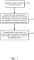
- FIG. 4 is a block diagram of a calibration method in accordance with an example embodiment.
- baseline data may be gathered for one or more poses at operation 400.
- the baseline data may include information associated with roll, pitch, yaw, and other variables of interest including acceleration and velocity information for poses that include motion.
- the operator 110 may be guided through each of the one or more poses in order to obtain current data for comparison to the baseline data or the operator 110 may be sensed/detected in any of the one or more poses.
- the controller 140 may reset errors associated with the IMU-based sensors 120 based on the comparison, for any or all applicable poses.
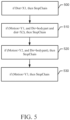
- the fusion rules may define a hierarchy of priority for the distance measurement information and motion tracking information based on proximity. For example, when a movement toward a body part is detected, as distance decreases, the distance measurement information will have increased authority, and as distance increases, the motion tracking information will have increased authority in relation to determining protective functions (if any).
- FIG. 5 is a block diagram showing an example of fusion rules that may be applied in accordance with an example embodiment. Within the context of FIG. 5 , the following term definitions apply:
- the transponder 600 may then reduce the transmit power from the transponder 600 to transmit a power reduced signal 640 having an incrementally lower value than the initial detection signal 620. If received with sufficient power, the tag 610 will send a power reduced response 650. The reader 600 will then reduce power again (e.g., incrementally) and repeat the incremental power reductions until no response is received from the tag 610.
- the signal associated with the last (i.e., lowest) power transmitted, when the tag 610 is no longer detected may be referred to as a distance marker signal 660. When the power of the distance marker signal 660 is determined, it can be seen that this power is proportional to distance in a fairly consistent and accurate way.
- detection range is generally exponentially proportional to the output power or transmit power of the reader 600.
- specific values may change from antenna to antenna (e.g., reader to reader), the proportionality is fairly consistent.
- an accurate mapping of power to detection range may be achieved, and small calibration adjustments may be made for individual antennas.
- Other correction factors e.g., for temperature
- the mappings may be stored in the memory 212, and accessible to the controller 140 for determining the distance measurement information. Accordingly, when the distance marker signal 660 is determined, the process above can be repeated (as shown by operation 670) to determine additional instances of the distance marker signal 660.
- time of flight when applied over short distances, which is generally the case for the context in which example embodiments operate, time of flight will be in the range of a few nanoseconds for light and radio waves, and therefore requires a relatively high sampling rate in order to achieve good accuracy.
- some embodiments may employ ultrasound transmitters and receivers (i.e., active, and not passive, ultrasound) since sound travels much slower. The slower wave travel may allow lower sampling frequencies to be employed while still achieving good accuracy.
- modifications or amplifications may further be employed as optional alterations or augmentations to the description above. These alterations or augmentations may be performed exclusive of one another or in any combination with each other. In some cases, such modifications or amplifications may include (1), the power tool may be a chainsaw, and the protective action may be activating a chain brake of the chainsaw when one of the first set of wearable sensors or the second set of wearable sensors is within a threshold distance of a respective one of the first tool sensor or the second tool sensor.
- the power tool may be a chainsaw or other power equipment such as power cutters with a blade or chain
- the protective action may be providing an audible or visual warning to the operator when one of the first set of wearable sensors or the second set of wearable sensors is within a threshold distance of a respective one of the first tool sensor of the second tool sensor.
- the first set of wearable sensors may include a plurality of inertial measurement unit (IMU)-based sensors, and the first tool sensor may be a tool position sensor.
- the second set of wearable sensors may include a plurality of distance sensors, and the second tool sensor may be a reader disposed at the power tool.
- the IMU-based sensors and the tool position sensor may be periodically calibrated based on predefined poses of the operator and corresponding positions of the power tool.
- the controller may be configured to store baseline data corresponding to known distances from each of the IMU-based sensors to the tool position sensor in each of the predefined poses. In such an example, the controller may be configured to perform a comparison of the baseline data to current data gathered in the predefined poses, and reset errors associated with the IMU-based sensors based on the comparison.
- the controller may be configured to obtain distance information from the plurality of distance sensors and the reader, and to obtain motion tracking information from the IMU-based sensors and the tool position sensor.
- the controller may be configured to prioritize the distance information over the motion tracking information within a predefined distance, and prioritize the motion tracking information over the distance information outside the predefined distance.
- the transponder may be a millimeter wave radar sensor with focus lenses for the beam.
- the reader may be a light or ultrasound transmitter, and the controller may be configured to calculate distance information based on time of flight measurements associated with the reader and the plurality of distance sensors.
- the reader may be an electromagnetic reader configured to detect electronic tags, and each of the plurality of distance sensors may be an electronic tag.
- any or all of modifications/amplifications (1) to (10) may be employed in any combination with each other.
- the system could just include either the first set of wearable sensors, where the sensors are configured to be calibrated (e.g., as in (4) and (5) above).
- the system may just include the second set of wearable sensors, where the sensors are configured as in (10) above.
Landscapes
- Engineering & Computer Science (AREA)
- Mechanical Engineering (AREA)
- Life Sciences & Earth Sciences (AREA)
- Forests & Forestry (AREA)
- General Engineering & Computer Science (AREA)
- Wood Science & Technology (AREA)
- General Physics & Mathematics (AREA)
- Environmental Sciences (AREA)
- Ecology (AREA)
- Physics & Mathematics (AREA)
- Biodiversity & Conservation Biology (AREA)
- Theoretical Computer Science (AREA)
- Human Computer Interaction (AREA)
- Radar, Positioning & Navigation (AREA)
- Remote Sensing (AREA)
- Length Measuring Devices With Unspecified Measuring Means (AREA)
- Portable Power Tools In General (AREA)
- Auxiliary Devices For Machine Tools (AREA)
- Sawing (AREA)
Claims (12)
- System zum Schutz einer Bedienungsperson (110) eines angetriebenen Werkzeugs, wobei das System Folgendes umfasst:einen ersten Satz von tragbaren Sensoren (120), die von der Bedienungsperson (110) getragen werden;einen zweiten Satz von tragbaren Sensoren (130), die von der Bedienungsperson (110) getragen werden;einen ersten Werkzeugsensor (122), der an dem angetriebenen Werkzeug angeordnet ist, wobei der erste Werkzeugsensor (122) so konfiguriert oder ausgebildet ist, dass er mit dem ersten Satz von tragbaren Sensoren (120) kommuniziert;einen zweiten Werkzeugsensor (132), der an dem angetriebenen Werkzeug angeordnet ist, wobei der zweite Werkzeugsensor (132) so konfiguriert oder ausgebildet ist, dass er mit dem zweiten Satz von tragbaren Sensoren (130) kommuniziert; undeine Steuerung (140), die ausgebildet ist, um auf der Grundlage von Abständen zwischen dem ersten Werkzeugsensor (122) und dem ersten Satz von tragbaren Sensoren (120) und zwischen dem zweiten Werkzeugsensor (132) und dem zweiten Satz von tragbaren Sensoren (130) zu bestimmen, ob eine Schutzmaßnahme in Bezug auf das angetriebene Werkzeug einzuleiten ist, dadurch gekennzeichnet, dassder erste Satz von tragbaren Sensoren (120) eine Vielzahl von Sensoren (120) auf der Basis einer Inertialen Messeinheit (inertial measurement unit; IMU) umfasst und der erste Werkzeugsensor (122) einen Sensor (122) für die Position des Werkzeugs umfasst, undwobei der zweite Satz von tragbaren Sensoren (130) eine Vielzahl von Abstandssensoren (130) umfasst, und der zweite Werkzeugsensor (132) ein am angetriebenen Werkzeug angeordnetes Lesegerät (132) umfasst, und wobei dieIMU-basierte Sensoren (120) und der Werkzeugpositionssensor (122) werden regelmäßig auf der Grundlage vordefinierter Posen der Bedienungsperson (110) und entsprechender Positionen des angetriebenen Werkzeugs kalibriert.
- System zum Schutz einer Bedienungsperson (110) eines angetriebenen Werkzeugs, wobei das System Folgendes umfasst:einen ersten Satz von tragbaren Sensoren (120), die von der Bedienungsperson (110) getragen werden;einen zweiten Satz von tragbaren Sensoren (130), die von der Bedienungsperson (110) getragen werden;einen ersten Werkzeugsensor (122), der an dem angetriebenen Werkzeug angeordnet ist, wobei der erste Werkzeugsensor (122) so konfiguriert oder ausgebildet ist, dass er mit dem ersten Satz von tragbaren Sensoren (120) kommuniziert;einen zweiten Werkzeugsensor (132), der an dem angetriebenen Werkzeug angeordnet ist, wobei der zweite Werkzeugsensor (132) so konfiguriert oder ausgebildet ist, dass er mit dem zweiten Satz von tragbaren Sensoren (130) kommuniziert; undeine Steuerung (140), die ausgebildet ist, um auf der Grundlage von Abständen zwischen dem ersten Werkzeugsensor (122) und dem ersten Satz von tragbaren Sensoren (120) und zwischen dem zweiten Werkzeugsensor (132) und dem zweiten Satz von tragbaren Sensoren (130) zu bestimmen, ob eine Schutzmaßnahme in Bezug auf das angetriebene Werkzeug einzuleiten ist, dadurch gekennzeichnet, dassder erste Satz von tragbaren Sensoren (120) eine Vielzahl von Sensoren (120) auf der Basis einer Inertialen Messeinheit (IMU) umfasst und der erste Werkzeugsensor (122) einen Sensor (122) für die Position des Werkzeugs umfasst, undwobei der zweite Satz von tragbaren Sensoren (130) eine Vielzahl von Abstandssensoren (130) umfasst, und der zweite Werkzeugsensor (132) ein am angetriebenen Werkzeug angeordnetes Lesegerät (132) umfasst, und wobei
die Steuerung (140) konfiguriert oder ausgebildet ist, um Abstandsinformationen von der Vielzahl von Abstandssensoren (130) und dem Lesegerät (132) zu erhalten, und um Bewegungsverfolgungsinformationen von den IMU-basierten Sensoren (120) und dem Werkzeugpositionssensor (122) zu erhalten, undwobei die Steuerung (140) so konfiguriert oder ausgebildet ist, dass sie innerhalb eines vordefinierten Abstands die Abstandsinformationen gegenüber den Bewegungsverfolgungsinformationen priorisiert und außerhalb des vordefinierten Abstands die Bewegungsverfolgungsinformationen gegenüber den Abstandsinformationen priorisiert. - System zum Schutz einer Bedienungsperson (110) eines angetriebenen Werkzeugs, wobei das System Folgendes umfasst:einen ersten Satz von tragbaren Sensoren (120), die von der Bedienungsperson (110) getragen werden;einen zweiten Satz von tragbaren Sensoren (130), die von der Bedienungsperson (110) getragen werden;einen ersten Werkzeugsensor (122), der an dem angetriebenen Werkzeug angeordnet ist, wobei der erste Werkzeugsensor (122) so konfiguriert oder ausgebildet ist, dass er mit dem ersten Satz von tragbaren Sensoren (120) kommuniziert;einen zweiten Werkzeugsensor (132), der an dem angetriebenen Werkzeug angeordnet ist, wobei der zweite Werkzeugsensor (132) so konfiguriert oder ausgebildet ist, dass er mit dem zweiten Satz von tragbaren Sensoren (130) kommuniziert; und
eine Steuerung (140), die ausgebildet ist, um auf der Grundlage von Abständen zwischen dem ersten Werkzeugsensor (122) und dem ersten Satz von tragbaren Sensoren (120) und zwischen dem zweiten Werkzeugsensor (132) und dem zweiten Satz von tragbaren Sensoren (130) zu bestimmen, ob eine Schutzmaßnahme in Bezug auf das angetriebene Werkzeug einzuleiten ist, dadurch gekennzeichnet, dassder erste Satz von tragbaren Sensoren (120) eine Vielzahl von Sensoren (120) auf der Basis einer Inertialen Messeinheit (IMU) umfasst und der erste Werkzeugsensor (122) einen Sensor (122) für die Position des Werkzeugs umfasst, undwobei der zweite Satz von tragbaren Sensoren (130) eine Vielzahl von Abstandssensoren (130) umfasst, und der zweite Werkzeugsensor (132) ein Lesegerät (132) umfasst, das an dem angetriebenen Werkzeug angeordnet ist, und wobei das Lesegerät (132) ein elektromagnetisches Funklesegerät (600) ist, das ausgebildet ist, um elektronische Etiketten (610) zu erfassen, undwobei jeder der mehreren Abstandssensoren (130) ein elektronisches Etikett (610) ist, wobei der Steuerung (140) konfiguriert oder ausgebildet ist, um:a) die Sendeleistung erhöhen, bis ein Fall des elektronischen Etiketts (610) erkannt wird;b) die Leistung zu reduzieren, bis die Instanz des elektronischen Etiketts (610) nicht mehr erkannt wird;c) Wiederholen der Schritte a) und b), um eine mittlere oder durchschnittliche Leistung zu bestimmen, bei der das elektronische Etikett (610) nicht mehr erkannt wird; undd) Bestimmen einer Reichweite zwischen dem Lesegerät (600) und der Instanz des elektronischen Etiketts (610) auf der Grundlage der mittleren oder durchschnittlichen Leistung. - System nach Anspruch 1, 2 oder 3, wobei das angetriebene Werkzeug eine Kettensäge (100) oder ein anderes kraftbetriebenes Gerät ist, wie z.B. ein Trennschleifer mit Klinge oder Kette (102), und wobei die Schutzmaßnahme das Aktivieren einer Kettenbremse (170) der Kettensäge (100) umfasst, wenn sich einer des ersten Satzes tragbarer Sensoren (120) oder des zweiten Satzes tragbarer Sensoren (130) innerhalb eines Schwellenabstands zu einem jeweiligen Sensor des ersten Werkzeugs (122) oder des zweiten Werkzeugs (132) befindet, oder wenn die Geschwindigkeit des angetriebenen Werkzeugs relativ zum Körper der Bedienungsperson (110) über einem Geschwindigkeitsschwellenwert liegt, oder wenn die Beschleunigung des angetriebenen Werkzeugs relativ zum Körper der Bedienungsperson (110) über einem Beschleunigungsschwellenwert liegt.
- System nach Anspruch 1, 2 oder 3, wobei das angetriebene Werkzeug eine Kettensäge (100) oder ein anderes kraftbetriebenes Gerät ist, wie z.B. ein Trennschleifer mit Klinge oder Kette (102), und wobei die Schutzmaßnahme darin besteht, eine akustische oder visuelle Warnung für die Bedienungsperson (110) bereitzustellen, wenn sich einer des ersten Satzes tragbarer Sensoren (120) oder des zweiten Satzes tragbarer Sensoren (130) innerhalb eines Schwellenabstands zu einem jeweiligen ersten Werkzeugsensor (122) oder zweiten Werkzeugsensor (132) befindet.
- System nach einem der Ansprüche 2 oder 3, wobei die IMU-basierten Sensoren (120) und der Werkzeugpositionssensor (122) regelmäßig auf der Grundlage vordefinierter Posen der Bedienungsperson (110) und entsprechender Positionen des angetriebenen Werkzeugs kalibriert werden.
- System nach Anspruch 1, 2 oder 3, wobei die Steuerung (140) Basisdaten speichert, die bekannten Abständen von jedem der IMU-basierten Sensoren (120) zum Sensor (122) für die Position des Werkzeugs in jeder der vordefinierten Posen (400) entsprechen,wobei der Steuerung (140) so konfiguriert oder ausgebildet ist, dass er einen Vergleich der Basisdaten mit aktuellen Daten, die in den vordefinierten Posen (410) gesammelt wurden, durchführt, undwobei der Steuerung (140) ausgebildet ist, um Fehler, die mit den IMU-basierten Sensoren (120) verbunden sind, basierend auf dem Vergleich (420) zurückzusetzen.
- System nach Anspruch 1 oder 3, wobei die Steuerung (140) konfiguriert oder ausgebildet ist, um Abstandsinformationen von der Vielzahl von Abstandssensoren (130) und dem Lesegerät (132) zu erhalten, und um Bewegungsverfolgungsinformationen von den IMU-basierten Sensoren (120) und dem Werkzeugpositionssensor (122) zu erhalten, und
wobei die Steuerung (140) so konfiguriert oder ausgebildet ist, dass sie innerhalb eines vordefinierten Abstands die Abstandsinformationen gegenüber den Bewegungsverfolgungsinformationen priorisiert und außerhalb des vordefinierten Abstands die Bewegungsverfolgungsinformationen gegenüber den Abstandsinformationen priorisiert. - System nach Anspruch 1, 2 oder 3, wobei das Lesegerät (132) ein Millimeterwellen-Radarsensor mit oder ohne Radarstrahl-Linsen ist.
- System nach Anspruch 1, 2 oder 3, wobei das Lesegerät (132) ein Funk-, Licht- oder Ultraschallsender ist und
wobei der Steuerung (140) ausgebildet ist, um Entfernungsinformationen auf der Grundlage von Flugzeitmessungen zu berechnen, die mit dem Lesegerät (132) und der Vielzahl von Entfernungssensoren (130) verbunden sind. - System nach Anspruch 1 oder 2, wobei das Lesegerät (132) ein elektromagnetisches Funklesegerät (600) ist, das so konfiguriert oder ausgebildet ist, dass es elektronische Etiketten (610) erkennt, und
wobei jeder der mehreren Abstandssensoren (130) ein elektronisches Etikett (610) ist. - System nach Anspruch 11, wobei der Steuerung (140) konfiguriert oder ausgebildet ist, um:a) die Sendeleistung erhöhen, bis ein Fall des elektronischen Etiketts (610) erkannt wird;b) die Leistung zu reduzieren, bis die Instanz des elektronischen Etiketts (610) nicht mehr erkannt wird;c) Wiederholen der Schritte a) und b), um eine mittlere oder durchschnittliche Leistung zu bestimmen, bei der das elektronische Etikett (610) nicht mehr erkannt wird; undd) Bestimmen einer Reichweite zwischen dem Lesegerät (600) und der Instanz des elektronischen Etiketts (610) auf der Grundlage der mittleren oder durchschnittlichen Leistung.
Applications Claiming Priority (2)
| Application Number | Priority Date | Filing Date | Title |
|---|---|---|---|
| SE2050466A SE543699C2 (en) | 2020-04-23 | 2020-04-23 | System for protecting an operator of a power tool |
| PCT/SE2021/050371 WO2021215992A1 (en) | 2020-04-23 | 2021-04-22 | System for protecting an operator of a power tool |
Publications (2)
| Publication Number | Publication Date |
|---|---|
| EP4139075A1 EP4139075A1 (de) | 2023-03-01 |
| EP4139075B1 true EP4139075B1 (de) | 2025-04-16 |
Family
ID=75787193
Family Applications (1)
| Application Number | Title | Priority Date | Filing Date |
|---|---|---|---|
| EP21723445.9A Active EP4139075B1 (de) | 2020-04-23 | 2021-04-22 | System zum schutz eines bedieners eines elektrowerkzeugs |
Country Status (7)
| Country | Link |
|---|---|
| US (1) | US20220388081A1 (de) |
| EP (1) | EP4139075B1 (de) |
| JP (2) | JP2023522283A (de) |
| CN (1) | CN114007789A (de) |
| AU (1) | AU2021259071A1 (de) |
| SE (1) | SE543699C2 (de) |
| WO (1) | WO2021215992A1 (de) |
Families Citing this family (13)
| Publication number | Priority date | Publication date | Assignee | Title |
|---|---|---|---|---|
| EP3872978B1 (de) * | 2018-11-28 | 2022-12-21 | Nanjing Chervon Industry Co., Ltd. | Kettensäge |
| CN113211390B (zh) * | 2020-06-03 | 2022-05-27 | 德丰电创科技股份有限公司 | 一种用于控制电动设备运行的系统 |
| CA3159512A1 (en) * | 2021-05-21 | 2022-11-21 | Gryp Technologies Inc. | Method and system for cueing a user of a tool |
| EP4111849B1 (de) | 2021-07-01 | 2025-09-03 | Andreas Stihl AG & Co. KG | Verfahren zum betreiben eines handgeführten bearbeitungsgeräts und bearbeitungssystem |
| US12369662B2 (en) * | 2022-05-27 | 2025-07-29 | Milwaukee Electric Tool Corporation | Protective garments |
| US20260020556A1 (en) * | 2022-09-15 | 2026-01-22 | Zasso Group Ag | User operated electric weeding system and method for activating a user operated electric weeding system |
| WO2024099930A1 (en) * | 2022-11-07 | 2024-05-16 | Husqvarna Ab | System for protecting an operator of a power tool using electronic tags |
| WO2024099932A1 (en) * | 2022-11-07 | 2024-05-16 | Husqvarna Ab | System for protecting an operator of a power tool having infrared sensors |
| SE545560C2 (en) * | 2022-11-07 | 2023-10-24 | Husqvarna Ab | System for determining an orientation of an inertial-magnetic measurement unit using magnetic fluid |
| WO2024099933A1 (en) * | 2022-11-07 | 2024-05-16 | Husqvarna Ab | System for protecting an operator of a power tool having a camera |
| CN116018949A (zh) * | 2022-12-05 | 2023-04-28 | 四川依贝智能装备有限公司 | 一种感应待机的绿篱机 |
| SE2230447A1 (en) * | 2023-01-13 | 2024-07-14 | Nordquist & Nordquist AB | NFC-baserat sågkedjeskydd |
| WO2025262448A1 (en) * | 2024-06-18 | 2025-12-26 | Innovation Fabrication Commercialisation Infaco | Portable power cutting tool with contactless security system and control process of safety system |
Family Cites Families (30)
| Publication number | Priority date | Publication date | Assignee | Title |
|---|---|---|---|---|
| DE60238424D1 (de) * | 2001-07-11 | 2011-01-05 | Black & Decker Inc | Sicherheitsmechanismen für ein strombetriebenes werkzeug |
| DE102006014819A1 (de) * | 2006-03-29 | 2007-10-04 | Dolmar Gmbh | Verfahren zur Steuerung eines Motorwerkzeugs |
| DE102007032221A1 (de) * | 2007-07-11 | 2009-01-15 | Robert Bosch Gmbh | Werkzeugmaschine und Verfahren mit einer Werkzeugmaschine |
| DE102007035822A1 (de) * | 2007-07-31 | 2009-02-05 | Robert Bosch Gmbh | Automatische Sicherheitsabschaltung von Werkzeugen oder Arbeitsgeräten |
| US20100064532A1 (en) * | 2007-07-31 | 2010-03-18 | Edward Raymond Wittke | Chain saw 3D relative positional monitoring and anti-kickback actuation system |
| US8752301B2 (en) * | 2009-04-08 | 2014-06-17 | Rex George | Chainsaw incorporating a safety device system |
| US8516706B2 (en) * | 2010-01-08 | 2013-08-27 | Syneron Medical Ltd | Skin-heating shaving apparatus and method |
| US20170113316A1 (en) * | 2010-06-21 | 2017-04-27 | William Alexander Barr | Locating Device for Use with Power Tools |
| DE102010030825A1 (de) * | 2010-07-01 | 2012-01-05 | Hilti Aktiengesellschaft | Handwerkzeuggerät |
| DE102010025900A1 (de) * | 2010-07-02 | 2012-01-05 | Ott-Jakob Spanntechnik Gmbh | Vorrichtung zum Schutz einer Arbeitsspindel |
| ITMI20101566A1 (it) * | 2010-08-24 | 2012-02-25 | Redcap Technology S R L | Sistema di sicurezza capacitivo per motoseghe ed attrezzi da taglio |
| WO2012098609A1 (ja) * | 2011-01-17 | 2012-07-26 | パナソニック株式会社 | 安全装置および予備動作判定方法 |
| US8890684B2 (en) * | 2011-06-17 | 2014-11-18 | Checkpoint Systems, Inc. | Background object sensor |
| US11040458B2 (en) * | 2012-12-31 | 2021-06-22 | Matthew W. Krenik | Hair cutting device for automated hair cutting system |
| WO2014210022A1 (en) * | 2013-06-26 | 2014-12-31 | University Of Virginia Patent Foundation | Real-time rfid localization using uniform, high-performance tags and related method thereof |
| US20150260823A1 (en) * | 2014-03-11 | 2015-09-17 | Crestron Electronics, Inc. | Method of enclosing and powering a bluetooth emitter |
| US11117204B2 (en) * | 2014-05-06 | 2021-09-14 | Husqvarna Ab | Power tool |
| WO2016124415A1 (en) * | 2015-02-05 | 2016-08-11 | Koninklijke Philips N.V. | Safety system, workflow management system, safety method and computer program product |
| CN106033201A (zh) * | 2015-02-10 | 2016-10-19 | 苏州宝时得电动工具有限公司 | 可穿戴设备及电动工具 |
| WO2016127936A1 (zh) * | 2015-02-10 | 2016-08-18 | 苏州宝时得电动工具有限公司 | 可穿戴设备及系统 |
| CA2992896A1 (en) * | 2015-07-20 | 2017-01-26 | Jobsafe Systems Inc. | Automated system and process for providing personal safety |
| DE102015226190A1 (de) * | 2015-12-21 | 2017-06-22 | Robert Bosch Gmbh | System mit zumindest einer Werkzeugmaschine und mit zumindest einer mobilen Sensorvorrichtung |
| EP3432782A4 (de) * | 2016-03-24 | 2019-11-13 | Warwick Mills, Inc. | Am körper tragbares sicherheitswarn- und messsystem |
| SE539516C2 (en) * | 2016-03-31 | 2017-10-03 | Husqvarna Ab | Handheld chainsaw comprising at least one orientation sensor, a method of using the chainsaw and a mobile telephone to establish a connection to the chainsaw |
| WO2017197308A1 (en) * | 2016-05-12 | 2017-11-16 | One Million Metrics Corp. | System and method for monitoring safety and productivity of physical tasks |
| US10807219B2 (en) * | 2016-09-07 | 2020-10-20 | Milwaukee Electric Tool Corporation | Depth and angle sensor attachment for a power tool |
| US10646139B2 (en) * | 2016-12-05 | 2020-05-12 | Intel Corporation | Body movement tracking |
| US10837599B2 (en) * | 2018-02-08 | 2020-11-17 | Alken Inc. | Safety system for machinery |
| DE102019108793A1 (de) * | 2018-06-12 | 2019-12-12 | Festool Gmbh | Hand-Werkzeugmaschine |
| GB2587774A (en) * | 2019-06-10 | 2021-04-14 | Sutherland Greig | Arborist apparatus |
-
2020
- 2020-04-23 SE SE2050466A patent/SE543699C2/en unknown
-
2021
- 2021-04-22 JP JP2021576405A patent/JP2023522283A/ja active Pending
- 2021-04-22 CN CN202180003999.3A patent/CN114007789A/zh active Pending
- 2021-04-22 WO PCT/SE2021/050371 patent/WO2021215992A1/en not_active Ceased
- 2021-04-22 US US17/619,680 patent/US20220388081A1/en active Pending
- 2021-04-22 EP EP21723445.9A patent/EP4139075B1/de active Active
- 2021-04-22 AU AU2021259071A patent/AU2021259071A1/en active Pending
-
2025
- 2025-01-29 JP JP2025013148A patent/JP2025069274A/ja active Pending
Also Published As
| Publication number | Publication date |
|---|---|
| SE2050466A1 (en) | 2021-06-15 |
| AU2021259071A1 (en) | 2022-01-20 |
| EP4139075A1 (de) | 2023-03-01 |
| US20220388081A1 (en) | 2022-12-08 |
| JP2025069274A (ja) | 2025-04-30 |
| JP2023522283A (ja) | 2023-05-30 |
| WO2021215992A1 (en) | 2021-10-28 |
| SE543699C2 (en) | 2021-06-15 |
| CN114007789A (zh) | 2022-02-01 |
Similar Documents
| Publication | Publication Date | Title |
|---|---|---|
| EP4139075B1 (de) | System zum schutz eines bedieners eines elektrowerkzeugs | |
| US10668545B2 (en) | Power equipment with inertia based measurement and guidance | |
| CN113156364B (zh) | 安全系统和方法 | |
| KR101251184B1 (ko) | 구동 명령을 이용한 비젼 트래킹 시스템 및 방법 | |
| WO2017093289A2 (en) | Robotic safety using wearables | |
| CN114340849B (zh) | 工具机装置 | |
| EP4205914A1 (de) | System und verfahren zur bestimmung der zulässigen robotergeschwindigkeit in einem kollaborativen arbeitsraum | |
| CN114636967A (zh) | 安全系统和使用安全系统的方法 | |
| JP2014174790A (ja) | ウェアラブルコンピュータ入力装置 | |
| WO2022229694A1 (en) | Method for measure a displacement of an outdoor power tool and electronic device for carrying-out the method | |
| US20240201649A1 (en) | Device for monitoring the position and/or attitude and/or movement of a tool | |
| Forlini et al. | Experimental implementation of skeleton tracking for collision avoidance in collaborative robotics | |
| CN114365165B (zh) | 施工管理系统以及作业机械 | |
| EP3796206B1 (de) | Systeme, verfahren und vorrichtungen zur überwachung der compliance von persönlichen schutzausrüstungen | |
| EP3695158A1 (de) | Sicherheitseinrichtung für werkzeugmaschinen | |
| SE2251296A1 (en) | System for determining an orientation of an inertial-magnetic measurement unit using magnetic fluid | |
| US20250375915A1 (en) | System for employing sensor fusion with respect to protecting an operator of a power tool | |
| WO2024099933A1 (en) | System for protecting an operator of a power tool having a camera | |
| Marvel | Sensors for safe, collaborative robots in smart manufacturing | |
| KR20210035669A (ko) | 가상현실 기반 주행형 농업기계의 안전교육을 위한 손 동작 추적 시스템 및 방법 | |
| WO2024099930A1 (en) | System for protecting an operator of a power tool using electronic tags | |
| WO2018018574A1 (zh) | 人员保护系统及其运行方法 | |
| WO2024099932A1 (en) | System for protecting an operator of a power tool having infrared sensors | |
| WO2024099929A1 (en) | System for protecting an operator of a power tool using time-of-flight sensors | |
| WO2025262448A1 (en) | Portable power cutting tool with contactless security system and control process of safety system |
Legal Events
| Date | Code | Title | Description |
|---|---|---|---|
| STAA | Information on the status of an ep patent application or granted ep patent |
Free format text: STATUS: UNKNOWN |
|
| STAA | Information on the status of an ep patent application or granted ep patent |
Free format text: STATUS: THE INTERNATIONAL PUBLICATION HAS BEEN MADE |
|
| PUAI | Public reference made under article 153(3) epc to a published international application that has entered the european phase |
Free format text: ORIGINAL CODE: 0009012 |
|
| STAA | Information on the status of an ep patent application or granted ep patent |
Free format text: STATUS: REQUEST FOR EXAMINATION WAS MADE |
|
| 17P | Request for examination filed |
Effective date: 20220928 |
|
| AK | Designated contracting states |
Kind code of ref document: A1 Designated state(s): AL AT BE BG CH CY CZ DE DK EE ES FI FR GB GR HR HU IE IS IT LI LT LU LV MC MK MT NL NO PL PT RO RS SE SI SK SM TR |
|
| DAV | Request for validation of the european patent (deleted) | ||
| DAX | Request for extension of the european patent (deleted) | ||
| GRAP | Despatch of communication of intention to grant a patent |
Free format text: ORIGINAL CODE: EPIDOSNIGR1 |
|
| STAA | Information on the status of an ep patent application or granted ep patent |
Free format text: STATUS: GRANT OF PATENT IS INTENDED |
|
| INTG | Intention to grant announced |
Effective date: 20250123 |
|
| GRAS | Grant fee paid |
Free format text: ORIGINAL CODE: EPIDOSNIGR3 |
|
| GRAA | (expected) grant |
Free format text: ORIGINAL CODE: 0009210 |
|
| STAA | Information on the status of an ep patent application or granted ep patent |
Free format text: STATUS: THE PATENT HAS BEEN GRANTED |
|
| AK | Designated contracting states |
Kind code of ref document: B1 Designated state(s): AL AT BE BG CH CY CZ DE DK EE ES FI FR GB GR HR HU IE IS IT LI LT LU LV MC MK MT NL NO PL PT RO RS SE SI SK SM TR |
|
| REG | Reference to a national code |
Ref country code: GB Ref legal event code: FG4D |
|
| P01 | Opt-out of the competence of the unified patent court (upc) registered |
Free format text: CASE NUMBER: APP_13771/2025 Effective date: 20250320 |
|
| REG | Reference to a national code |
Ref country code: CH Ref legal event code: EP |
|
| REG | Reference to a national code |
Ref country code: IE Ref legal event code: FG4D |
|
| REG | Reference to a national code |
Ref country code: DE Ref legal event code: R096 Ref document number: 602021029226 Country of ref document: DE |
|
| PGFP | Annual fee paid to national office [announced via postgrant information from national office to epo] |
Ref country code: DE Payment date: 20250409 Year of fee payment: 5 |
|
| PGFP | Annual fee paid to national office [announced via postgrant information from national office to epo] |
Ref country code: AT Payment date: 20250721 Year of fee payment: 5 |
|
| REG | Reference to a national code |
Ref country code: NL Ref legal event code: MP Effective date: 20250416 |
|
| PG25 | Lapsed in a contracting state [announced via postgrant information from national office to epo] |
Ref country code: NL Free format text: LAPSE BECAUSE OF FAILURE TO SUBMIT A TRANSLATION OF THE DESCRIPTION OR TO PAY THE FEE WITHIN THE PRESCRIBED TIME-LIMIT Effective date: 20250416 |
|
| REG | Reference to a national code |
Ref country code: AT Ref legal event code: MK05 Ref document number: 1785256 Country of ref document: AT Kind code of ref document: T Effective date: 20250416 |
|
| PG25 | Lapsed in a contracting state [announced via postgrant information from national office to epo] |
Ref country code: FI Free format text: LAPSE BECAUSE OF FAILURE TO SUBMIT A TRANSLATION OF THE DESCRIPTION OR TO PAY THE FEE WITHIN THE PRESCRIBED TIME-LIMIT Effective date: 20250416 Ref country code: ES Free format text: LAPSE BECAUSE OF FAILURE TO SUBMIT A TRANSLATION OF THE DESCRIPTION OR TO PAY THE FEE WITHIN THE PRESCRIBED TIME-LIMIT Effective date: 20250416 Ref country code: PT Free format text: LAPSE BECAUSE OF FAILURE TO SUBMIT A TRANSLATION OF THE DESCRIPTION OR TO PAY THE FEE WITHIN THE PRESCRIBED TIME-LIMIT Effective date: 20250818 |
|
| REG | Reference to a national code |
Ref country code: LT Ref legal event code: MG9D |
|
| PG25 | Lapsed in a contracting state [announced via postgrant information from national office to epo] |
Ref country code: NO Free format text: LAPSE BECAUSE OF FAILURE TO SUBMIT A TRANSLATION OF THE DESCRIPTION OR TO PAY THE FEE WITHIN THE PRESCRIBED TIME-LIMIT Effective date: 20250716 Ref country code: GR Free format text: LAPSE BECAUSE OF FAILURE TO SUBMIT A TRANSLATION OF THE DESCRIPTION OR TO PAY THE FEE WITHIN THE PRESCRIBED TIME-LIMIT Effective date: 20250717 |
|
| PG25 | Lapsed in a contracting state [announced via postgrant information from national office to epo] |
Ref country code: PL Free format text: LAPSE BECAUSE OF FAILURE TO SUBMIT A TRANSLATION OF THE DESCRIPTION OR TO PAY THE FEE WITHIN THE PRESCRIBED TIME-LIMIT Effective date: 20250416 |
|
| PG25 | Lapsed in a contracting state [announced via postgrant information from national office to epo] |
Ref country code: BG Free format text: LAPSE BECAUSE OF FAILURE TO SUBMIT A TRANSLATION OF THE DESCRIPTION OR TO PAY THE FEE WITHIN THE PRESCRIBED TIME-LIMIT Effective date: 20250416 |
|
| PG25 | Lapsed in a contracting state [announced via postgrant information from national office to epo] |
Ref country code: HR Free format text: LAPSE BECAUSE OF FAILURE TO SUBMIT A TRANSLATION OF THE DESCRIPTION OR TO PAY THE FEE WITHIN THE PRESCRIBED TIME-LIMIT Effective date: 20250416 |
|
| PG25 | Lapsed in a contracting state [announced via postgrant information from national office to epo] |
Ref country code: AT Free format text: LAPSE BECAUSE OF FAILURE TO SUBMIT A TRANSLATION OF THE DESCRIPTION OR TO PAY THE FEE WITHIN THE PRESCRIBED TIME-LIMIT Effective date: 20250416 |
|
| PG25 | Lapsed in a contracting state [announced via postgrant information from national office to epo] |
Ref country code: RS Free format text: LAPSE BECAUSE OF FAILURE TO SUBMIT A TRANSLATION OF THE DESCRIPTION OR TO PAY THE FEE WITHIN THE PRESCRIBED TIME-LIMIT Effective date: 20250716 |
|
| PG25 | Lapsed in a contracting state [announced via postgrant information from national office to epo] |
Ref country code: IS Free format text: LAPSE BECAUSE OF FAILURE TO SUBMIT A TRANSLATION OF THE DESCRIPTION OR TO PAY THE FEE WITHIN THE PRESCRIBED TIME-LIMIT Effective date: 20250816 |
|
| PG25 | Lapsed in a contracting state [announced via postgrant information from national office to epo] |
Ref country code: LV Free format text: LAPSE BECAUSE OF FAILURE TO SUBMIT A TRANSLATION OF THE DESCRIPTION OR TO PAY THE FEE WITHIN THE PRESCRIBED TIME-LIMIT Effective date: 20250416 |
|
| REG | Reference to a national code |
Ref country code: CH Ref legal event code: H13 Free format text: ST27 STATUS EVENT CODE: U-0-0-H10-H13 (AS PROVIDED BY THE NATIONAL OFFICE) Effective date: 20251125 |
|
| PG25 | Lapsed in a contracting state [announced via postgrant information from national office to epo] |
Ref country code: LU Free format text: LAPSE BECAUSE OF NON-PAYMENT OF DUE FEES Effective date: 20250422 |
|
| REG | Reference to a national code |
Ref country code: BE Ref legal event code: MM Effective date: 20250430 |
|
| PG25 | Lapsed in a contracting state [announced via postgrant information from national office to epo] |
Ref country code: SM Free format text: LAPSE BECAUSE OF FAILURE TO SUBMIT A TRANSLATION OF THE DESCRIPTION OR TO PAY THE FEE WITHIN THE PRESCRIBED TIME-LIMIT Effective date: 20250416 Ref country code: DK Free format text: LAPSE BECAUSE OF FAILURE TO SUBMIT A TRANSLATION OF THE DESCRIPTION OR TO PAY THE FEE WITHIN THE PRESCRIBED TIME-LIMIT Effective date: 20250416 |
|
| PG25 | Lapsed in a contracting state [announced via postgrant information from national office to epo] |
Ref country code: BE Free format text: LAPSE BECAUSE OF NON-PAYMENT OF DUE FEES Effective date: 20250430 |
|
| PG25 | Lapsed in a contracting state [announced via postgrant information from national office to epo] |
Ref country code: CH Free format text: LAPSE BECAUSE OF NON-PAYMENT OF DUE FEES Effective date: 20250430 |
|
| REG | Reference to a national code |
Ref country code: DE Ref legal event code: R097 Ref document number: 602021029226 Country of ref document: DE |
|
| PG25 | Lapsed in a contracting state [announced via postgrant information from national office to epo] |
Ref country code: CZ Free format text: LAPSE BECAUSE OF FAILURE TO SUBMIT A TRANSLATION OF THE DESCRIPTION OR TO PAY THE FEE WITHIN THE PRESCRIBED TIME-LIMIT Effective date: 20250416 |
|
| PG25 | Lapsed in a contracting state [announced via postgrant information from national office to epo] |
Ref country code: EE Free format text: LAPSE BECAUSE OF FAILURE TO SUBMIT A TRANSLATION OF THE DESCRIPTION OR TO PAY THE FEE WITHIN THE PRESCRIBED TIME-LIMIT Effective date: 20250416 |
|
| PG25 | Lapsed in a contracting state [announced via postgrant information from national office to epo] |
Ref country code: SK Free format text: LAPSE BECAUSE OF FAILURE TO SUBMIT A TRANSLATION OF THE DESCRIPTION OR TO PAY THE FEE WITHIN THE PRESCRIBED TIME-LIMIT Effective date: 20250416 |
|
| PG25 | Lapsed in a contracting state [announced via postgrant information from national office to epo] |
Ref country code: IT Free format text: LAPSE BECAUSE OF FAILURE TO SUBMIT A TRANSLATION OF THE DESCRIPTION OR TO PAY THE FEE WITHIN THE PRESCRIBED TIME-LIMIT Effective date: 20250416 |
|
| PG25 | Lapsed in a contracting state [announced via postgrant information from national office to epo] |
Ref country code: MC Free format text: LAPSE BECAUSE OF FAILURE TO SUBMIT A TRANSLATION OF THE DESCRIPTION OR TO PAY THE FEE WITHIN THE PRESCRIBED TIME-LIMIT Effective date: 20250416 |
|
| PG25 | Lapsed in a contracting state [announced via postgrant information from national office to epo] |
Ref country code: RO Free format text: LAPSE BECAUSE OF FAILURE TO SUBMIT A TRANSLATION OF THE DESCRIPTION OR TO PAY THE FEE WITHIN THE PRESCRIBED TIME-LIMIT Effective date: 20250416 |
|
| PLBE | No opposition filed within time limit |
Free format text: ORIGINAL CODE: 0009261 |
|
| STAA | Information on the status of an ep patent application or granted ep patent |
Free format text: STATUS: NO OPPOSITION FILED WITHIN TIME LIMIT |
|
| REG | Reference to a national code |
Ref country code: CH Ref legal event code: L10 Free format text: ST27 STATUS EVENT CODE: U-0-0-L10-L00 (AS PROVIDED BY THE NATIONAL OFFICE) Effective date: 20260225 |
|
| 26N | No opposition filed |
Effective date: 20260119 |
|
| GBPC | Gb: european patent ceased through non-payment of renewal fee |
Effective date: 20250716 |
|
| PG25 | Lapsed in a contracting state [announced via postgrant information from national office to epo] |
Ref country code: GB Free format text: LAPSE BECAUSE OF NON-PAYMENT OF DUE FEES Effective date: 20250716 |
|
| PG25 | Lapsed in a contracting state [announced via postgrant information from national office to epo] |
Ref country code: IE Free format text: LAPSE BECAUSE OF NON-PAYMENT OF DUE FEES Effective date: 20250422 |
|
| PG25 | Lapsed in a contracting state [announced via postgrant information from national office to epo] |
Ref country code: FR Free format text: LAPSE BECAUSE OF NON-PAYMENT OF DUE FEES Effective date: 20250616 |