EP4138734B1 - Prothesenimplantatsysteme zur durchmesseranpassung - Google Patents
Prothesenimplantatsysteme zur durchmesseranpassung Download PDFInfo
- Publication number
- EP4138734B1 EP4138734B1 EP21745498.2A EP21745498A EP4138734B1 EP 4138734 B1 EP4138734 B1 EP 4138734B1 EP 21745498 A EP21745498 A EP 21745498A EP 4138734 B1 EP4138734 B1 EP 4138734B1
- Authority
- EP
- European Patent Office
- Prior art keywords
- frame
- valve
- docking
- connector
- valve frame
- Prior art date
- Legal status (The legal status is an assumption and is not a legal conclusion. Google has not performed a legal analysis and makes no representation as to the accuracy of the status listed.)
- Active
Links
Images




Classifications
-
- A—HUMAN NECESSITIES
- A61—MEDICAL OR VETERINARY SCIENCE; HYGIENE
- A61F—FILTERS IMPLANTABLE INTO BLOOD VESSELS; PROSTHESES; DEVICES PROVIDING PATENCY TO, OR PREVENTING COLLAPSING OF, TUBULAR STRUCTURES OF THE BODY, e.g. STENTS; ORTHOPAEDIC, NURSING OR CONTRACEPTIVE DEVICES; FOMENTATION; TREATMENT OR PROTECTION OF EYES OR EARS; BANDAGES, DRESSINGS OR ABSORBENT PADS; FIRST-AID KITS
- A61F2/00—Filters implantable into blood vessels; Prostheses, i.e. artificial substitutes or replacements for parts of the body; Appliances for connecting them with the body; Devices providing patency to, or preventing collapsing of, tubular structures of the body, e.g. stents
- A61F2/02—Prostheses implantable into the body
- A61F2/24—Heart valves ; Vascular valves, e.g. venous valves; Heart implants, e.g. passive devices for improving the function of the native valve or the heart muscle; Transmyocardial revascularisation [TMR] devices; Valves implantable in the body
- A61F2/2412—Heart valves ; Vascular valves, e.g. venous valves; Heart implants, e.g. passive devices for improving the function of the native valve or the heart muscle; Transmyocardial revascularisation [TMR] devices; Valves implantable in the body with soft flexible valve members, e.g. tissue valves shaped like natural valves
- A61F2/2418—Scaffolds therefor, e.g. support stents
-
- A—HUMAN NECESSITIES
- A61—MEDICAL OR VETERINARY SCIENCE; HYGIENE
- A61F—FILTERS IMPLANTABLE INTO BLOOD VESSELS; PROSTHESES; DEVICES PROVIDING PATENCY TO, OR PREVENTING COLLAPSING OF, TUBULAR STRUCTURES OF THE BODY, e.g. STENTS; ORTHOPAEDIC, NURSING OR CONTRACEPTIVE DEVICES; FOMENTATION; TREATMENT OR PROTECTION OF EYES OR EARS; BANDAGES, DRESSINGS OR ABSORBENT PADS; FIRST-AID KITS
- A61F2/00—Filters implantable into blood vessels; Prostheses, i.e. artificial substitutes or replacements for parts of the body; Appliances for connecting them with the body; Devices providing patency to, or preventing collapsing of, tubular structures of the body, e.g. stents
- A61F2/02—Prostheses implantable into the body
- A61F2/24—Heart valves ; Vascular valves, e.g. venous valves; Heart implants, e.g. passive devices for improving the function of the native valve or the heart muscle; Transmyocardial revascularisation [TMR] devices; Valves implantable in the body
- A61F2/2409—Support rings therefor, e.g. for connecting valves to tissue
-
- A—HUMAN NECESSITIES
- A61—MEDICAL OR VETERINARY SCIENCE; HYGIENE
- A61F—FILTERS IMPLANTABLE INTO BLOOD VESSELS; PROSTHESES; DEVICES PROVIDING PATENCY TO, OR PREVENTING COLLAPSING OF, TUBULAR STRUCTURES OF THE BODY, e.g. STENTS; ORTHOPAEDIC, NURSING OR CONTRACEPTIVE DEVICES; FOMENTATION; TREATMENT OR PROTECTION OF EYES OR EARS; BANDAGES, DRESSINGS OR ABSORBENT PADS; FIRST-AID KITS
- A61F2/00—Filters implantable into blood vessels; Prostheses, i.e. artificial substitutes or replacements for parts of the body; Appliances for connecting them with the body; Devices providing patency to, or preventing collapsing of, tubular structures of the body, e.g. stents
- A61F2/02—Prostheses implantable into the body
- A61F2/24—Heart valves ; Vascular valves, e.g. venous valves; Heart implants, e.g. passive devices for improving the function of the native valve or the heart muscle; Transmyocardial revascularisation [TMR] devices; Valves implantable in the body
- A61F2/2427—Devices for manipulating or deploying heart valves during implantation
- A61F2/2436—Deployment by retracting a sheath
-
- A—HUMAN NECESSITIES
- A61—MEDICAL OR VETERINARY SCIENCE; HYGIENE
- A61F—FILTERS IMPLANTABLE INTO BLOOD VESSELS; PROSTHESES; DEVICES PROVIDING PATENCY TO, OR PREVENTING COLLAPSING OF, TUBULAR STRUCTURES OF THE BODY, e.g. STENTS; ORTHOPAEDIC, NURSING OR CONTRACEPTIVE DEVICES; FOMENTATION; TREATMENT OR PROTECTION OF EYES OR EARS; BANDAGES, DRESSINGS OR ABSORBENT PADS; FIRST-AID KITS
- A61F2/00—Filters implantable into blood vessels; Prostheses, i.e. artificial substitutes or replacements for parts of the body; Appliances for connecting them with the body; Devices providing patency to, or preventing collapsing of, tubular structures of the body, e.g. stents
- A61F2/02—Prostheses implantable into the body
- A61F2/24—Heart valves ; Vascular valves, e.g. venous valves; Heart implants, e.g. passive devices for improving the function of the native valve or the heart muscle; Transmyocardial revascularisation [TMR] devices; Valves implantable in the body
- A61F2/2427—Devices for manipulating or deploying heart valves during implantation
- A61F2/2439—Expansion controlled by filaments
-
- A—HUMAN NECESSITIES
- A61—MEDICAL OR VETERINARY SCIENCE; HYGIENE
- A61F—FILTERS IMPLANTABLE INTO BLOOD VESSELS; PROSTHESES; DEVICES PROVIDING PATENCY TO, OR PREVENTING COLLAPSING OF, TUBULAR STRUCTURES OF THE BODY, e.g. STENTS; ORTHOPAEDIC, NURSING OR CONTRACEPTIVE DEVICES; FOMENTATION; TREATMENT OR PROTECTION OF EYES OR EARS; BANDAGES, DRESSINGS OR ABSORBENT PADS; FIRST-AID KITS
- A61F2220/00—Fixations or connections for prostheses classified in groups A61F2/00 - A61F2/26 or A61F2/82 or A61F9/00 or A61F11/00 or subgroups thereof
- A61F2220/0025—Connections or couplings between prosthetic parts, e.g. between modular parts; Connecting elements
- A61F2220/0033—Connections or couplings between prosthetic parts, e.g. between modular parts; Connecting elements made by longitudinally pushing a protrusion into a complementary-shaped recess, e.g. held by friction fit
-
- A—HUMAN NECESSITIES
- A61—MEDICAL OR VETERINARY SCIENCE; HYGIENE
- A61F—FILTERS IMPLANTABLE INTO BLOOD VESSELS; PROSTHESES; DEVICES PROVIDING PATENCY TO, OR PREVENTING COLLAPSING OF, TUBULAR STRUCTURES OF THE BODY, e.g. STENTS; ORTHOPAEDIC, NURSING OR CONTRACEPTIVE DEVICES; FOMENTATION; TREATMENT OR PROTECTION OF EYES OR EARS; BANDAGES, DRESSINGS OR ABSORBENT PADS; FIRST-AID KITS
- A61F2220/00—Fixations or connections for prostheses classified in groups A61F2/00 - A61F2/26 or A61F2/82 or A61F9/00 or A61F11/00 or subgroups thereof
- A61F2220/0025—Connections or couplings between prosthetic parts, e.g. between modular parts; Connecting elements
- A61F2220/0091—Connections or couplings between prosthetic parts, e.g. between modular parts; Connecting elements connected by a hinged linkage mechanism, e.g. of the single-bar or multi-bar linkage type
-
- A—HUMAN NECESSITIES
- A61—MEDICAL OR VETERINARY SCIENCE; HYGIENE
- A61F—FILTERS IMPLANTABLE INTO BLOOD VESSELS; PROSTHESES; DEVICES PROVIDING PATENCY TO, OR PREVENTING COLLAPSING OF, TUBULAR STRUCTURES OF THE BODY, e.g. STENTS; ORTHOPAEDIC, NURSING OR CONTRACEPTIVE DEVICES; FOMENTATION; TREATMENT OR PROTECTION OF EYES OR EARS; BANDAGES, DRESSINGS OR ABSORBENT PADS; FIRST-AID KITS
- A61F2250/00—Special features of prostheses classified in groups A61F2/00 - A61F2/26 or A61F2/82 or A61F9/00 or A61F11/00 or subgroups thereof
- A61F2250/0004—Special features of prostheses classified in groups A61F2/00 - A61F2/26 or A61F2/82 or A61F9/00 or A61F11/00 or subgroups thereof adjustable
- A61F2250/001—Special features of prostheses classified in groups A61F2/00 - A61F2/26 or A61F2/82 or A61F9/00 or A61F11/00 or subgroups thereof adjustable for adjusting a diameter
Definitions
- maladies may affect an individual's body.
- Such maladies may be of the individual's heart, and may include maladies of the individual's heart valves, including the aortic, mitral, tricuspid, and pulmonary valves.
- Stenosis for example, is a common and serious valve disease that may affect the operation of the heart valves and an individual's overall well-being.
- Implants may be provided that may replace or repair portions of a patient's heart.
- Prosthetic implants such as prosthetic valves, may be provided to replace a portion of a patient's heart.
- Prosthetic aortic, mitral, tricuspid, and even pulmonary valves may be provided.
- Such implants may have a range of working diameters that the implants are effectively utilized at.
- a prosthetic heart valve may be able to effectively operate within a working diameter range.
- the range may be relatively low, as care must be taken not to over-expand or under-expand a prosthetic heart valve.
- Over-expansion or under-expansion may lead to the inability of the valve leaflets of the prosthetic heart valve to coapt properly.
- Further issues may arise from an over-expansion or under-expansion of a prosthetic heart valve or other types of implants, including damage to the implant, dislodgement of the implant, or other issues arising from the implant being over-expanded or under-expanded.
- an implant typically selects an implant from an array of implants having different working diameters or ranges of working diameters.
- the working diameter of the implant is typically selected according to the diameter of the treatment site within the patient's body. Due to variation in the possible diameter of the treatment site in the patient's body, however, a practitioner may keep a large number of different implants on hand, which may be expensive and cumbersome. Further, such implants may still be utilized within a range of working diameters upon implantation.
- the practitioner may have available a 30 millimeter implant and a 25 millimeter implant, and may select the 25 millimeter diameter implant to expand to a working diameter of 27 millimeters, because a 27 millimeter implant may be too expensive to separately stock.
- US 2006/0287719 A1 relates to a two-stage or component-based valve prosthesis.
- the prosthetic valve comprises a support structure that is deployed at a treatment site.
- the prosthetic valve further comprises a valve member configured to be quickly connected to the support structure.
- the support structure may take the form of a stent that is expanded at the site of a native valve.
- the support structure is provided with a coupling means for attachment to the valve member, thereby fixing the position of the valve member in the body.
- Embodiments as disclosed herein may provide for increased flexibility of providing prosthetic implants having various working diameters, and for reducing expense associated with keeping a stock of prosthetic implants at various working diameters.
- a prosthetic valve having a docking frame that may have a relatively large range of working diameters.
- a valve frame is configured to dock with the docking frame.
- the valve frame may have a working diameter that is closely tailored to the diameter of the implantation site. Further, the valve frame may have a lesser working diameter range than the working diameter range of the docking frame. As disclosed herein, the valve frame may be optimized to operate at the diameter of the implantation site.
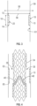
- FIG. 1 illustrates a perspective view of an implant in the form of a docking frame 10 that may be utilized according to embodiments herein.
- the docking frame 10 may be utilized as part of a system that may comprise a prosthetic valve system.
- the docking frame 10 may include a proximal end 12 and a distal end 14 and may have a length 16 (marked in FIG. 3 ) therebetween.
- the docking frame 10 may be configured to be implanted within a portion of a patient's body.
- the docking frame 10 may have an outer surface 18 and an inner surface 20 (marked in FIG. 3 ).
- the outer surface 18 may be configured to contact a portion of a patient's body to which the docking frame 10 is implanted and may comprise an anchoring surface.
- the outer surface 18 may be configured to apply a radially outward force to the portion of the patient's body to which the docking frame 10 is implanted.
- the inner surface 20 may be configured to surround a valve frame that the docking frame 10 is docked to in embodiments, and may face an interior flow channel 46 of the valve frame (as marked in FIG. 2 ).
- the docking frame 10 may comprise a mechanically expandable frame.
- a mechanism may be utilized to expand and contract the mechanically expandable frame, which may be a mechanical drive that couples to the docking frame 10.
- the mechanical drive may include a plurality of drive rods 32 that may couple to the docking frame 10 and be configured to rotate to control the expansion and contraction of the docking frame 10.
- the drive rods 32 may decouple from the docking frame 10.
- 9,913,716 illustrate such an operation and decoupling of a frame from drive rods.
- a mechanism may include a locking mechanism, as disclosed in U.S. Patent No. 9,913,716 , which may be utilized to lock the position of the expansion of the docking frame 10.
- the docking frame 10 may have a relatively large working diameter range. Such a large range may be allowed due to the construction of the docking frame 10, and due to the lack of valve leaflets coupled to the docking frame 10. As such, the docking frame 10 may be operably expanded to a relatively large range of working diameters and be effectively implanted within a patient's body.
- the working diameter range may be 14 millimeters in embodiments, or between working diameters of 32 millimeters and 18 millimeters. In other embodiments, greater or lesser working diameter ranges may be utilized, and the greatest working diameter (here 32 millimeters) and smallest working diameter (here 18 millimeters) may be greater or lesser in embodiments as desired.
- the greatest working diameter may be the greatest diameter that the docking frame 10 may operate effectively at, and the smallest working diameter may be the smallest diameter that the docking frame 10 may operate effectively at.
- the docking frame 10 may be configured to be balloon expandable, or may be self-expanding, among other methods of expansion.
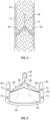
- FIG. 2 illustrates a cross sectional view of an embodiment of a valve frame 34 that may be utilized according to embodiments herein.
- the valve frame 34 may be utilized as part of a system that may comprise a prosthetic valve system.
- the valve frame 34 may be configured to dock to the docking frame 10 to support the valve frame 34 within the portion of the patient's body.
- the valve frame 34 may include a proximal end 36, a distal end 38, and a length 40 therebetween.
- the valve frame 34 may have an outer surface 42 and an inner surface 44.
- the outer surface 42 may be configured to face outward, towards the surface of the implantation site of the patient's body, and may face towards the inner surface 20 of the docking frame 10 in embodiments.
- the inner surface 44 may face towards a flow channel 46 within the valve frame 34.
- the valve frame 34 may include openings 35 that the docking frame 10 may be positioned within.
- the openings 35 may be positioned in the body 50 of the valve frame 34 and may comprise cut-outs in the outer surface 42 of the valve frame 34.
- valve frame 34 may be configured to be radially expandable.
- the valve frame 34 may include a frame body 50 that may be formed by a plurality of struts 52 separated by spaces in the forms of openings 54.
- the struts 52 may join together at junctures to form a repeating pattern of cells extending circumferentially about the axis that the valve frame 34 surrounds.
- the valve frame 34 may be configured to move from a compressed (or unexpanded or undeployed) state to an expanded (or deployed) state.
- the valve frame 34 may be configured to expand radially outward from an axis that the frame body 50 surrounds.
- the radial expansion of the frame body 50 may cause the length 40 to decrease with an increase in the width or diameter 60 of the valve frame 34. Such an operation may occur in a variety of manners.
- the junctures of the struts 52 may be flexible, or may comprise a hinge as disclosed in regard to FIG. 1 . Each juncture may allow the struts 52 to pivot about the juncture such that a width of each of the openings 54 between the struts 52 increases as the length of the openings decreases. Such a decrease in length and increase in width may allow the length 40 of the entire valve frame 34 to decrease and the width or diameter 60 to increase.
- the valve frame 34 may further be configured such that a reverse operation of decreasing the width of the openings 54 and increasing the length of the openings 54 allows the valve frame 34 to contract to the undeployed or unexpanded state.
- the valve frame 34 may have a cylindrical shape (half of which is shown in FIG. 2 ), similar to the docking frame 10 as shown in FIG. 1 or may have a variety of other shapes as desired.
- the valve frame 34 may have a "V" shape or bulb shape in embodiments as desired.
- the valve frame 34 may have a working diameter range.
- the range may extend between the greatest working diameter of the valve frame 34 and the smallest working diameter of the valve frame.
- the working diameter range of the docking frame 10 may be greater than a working diameter range of the valve frame 34.
- the working diameter range of the valve frame 34 may be less than the range of the docking frame 10 because leaflets 48 are coupled to the valve frame 34 that may be required to properly coapt during operation of the prosthetic valve, and thus the valve frame 34 may only operate within a defined range, which may be less than the range of operation of the docking frame 10.
- valve frame 34 may be less sturdy than the docking frame 10, which may reduce the amount that the valve frame 34 can expand and thus reduce working diameter range of the valve frame 34 relative to the working diameter range of the docking frame 10.
- the valve frame 34 may have a working diameter range of three millimeters in embodiments (e.g., between 26 and 29 millimeters). In embodiments, the working diameter range may be less than three millimeters (e.g., two millimeter, one millimeter, or lesser), or may be greater.
- the greatest working diameter of the docking frame 10 may also be greater than the greatest working diameter of the valve frame 34, as the docking frame 10 may have an ability to operably expand to a greater diameter.
- the greatest working diameter of the valve frame 34 for example, may be 29 millimeters and the greatest working diameter of the docking frame 10 may be 32 millimeters for example. Other values may be utilized in embodiments as desired.
- the valve frame 34 may be configured to be utilized with the docking frame 10 in a system within the patient's body.
- the docking frame 10 may be configured to be more robust and sturdy than the valve frame 34, and able to better withstand compressive forces applied to the system, which may be as a result of the radial expansion forces applied to the patient's body by the docking frame 10.
- the valve frame 34 may be configured to dock to the docking frame 10 and support the leaflets 48 within the portion of the patient's body.
- the valve frame 34 may be configured to be docked to the docking frame 10 within the patient's body, or may be configured to be docked to the docking frame 10 external to the patient's body and prior to insertion of the docking frame 10 within the patient's body in embodiments.
- FIGS. 3-5 illustrate features of a method of utilizing a system disclosed herein.
- the system may be deployed to a portion of a patient's body comprising the patient's vasculature, which may comprise the patient's arteries or other venous bodies.
- the system may be utilized as a prosthetic valve system, which may be utilized to replace or augment the operation of a native heart valve of the patient's body.
- the portion of the patient's body accordingly may comprise a native aortic valve, or in embodiments may comprise another valve such as the mitral, tricuspid, or pulmonary valve.
- the system may be deployed to the annulus of the native valve as desired, or another location.
- the system may be deployed in a sequence of steps, in which the docking frame 10 may be deployed within a portion of the patient's body first, with the valve frame 34 following. In other embodiments herein, the docking frame 10 may be deployed with the valve frame 34.
- the system may be deployed in an implantation procedure without pre-visualization or pre-computed tomography (CT) being performed of the patient.
- pre-CT is performed to determine the size of the patient's vasculature, to determine what size of implant to be implanted within the patient's vasculature.
- Such visualization is typically performed because the user (e.g., a medical clinician such as a surgeon) must select a size of implant to deploy within the patient's body and thus must know prior to the implantation procedure what is the size of the patient's vasculature.
- the system may be deployed without such pre-visualization of the size of the patient's vasculature occurring.
- Such a feature may reduce the number of visits that the patient must make to a medical clinician (such as a medical imaging clinician), and may simplify the implantation process.
- a medical clinician such as a medical imaging clinician
- Such a feature may be allowed as the docking frame 10 may be configured to expand to a variety of working diameters.
- the docking frame 10 may be passed into the patient's body mounted to a delivery apparatus (with a delivery shaft 33 of a delivery apparatus shown in FIG. 1 ). The docking frame 10 may then be deployed to the patient's vasculature and expanded radially outward to a diameter 56 as shown in FIG. 3 . The outer surface 18 of the docking frame 10 may be radially pressed outward against the inner surface 61 of the patient's vasculature.
- the docking frame 10 may be configured to expand to a variety of working diameters, and may be capable of expanding to a greater diameter if the surface of the patient's vasculature did not block the docking frame 10.
- Diameter 58 shown in FIG. 3 represents a greatest working diameter of the docking frame 10 that the frame 10 may operably expand to.
- the docking frame 10, however, as shown in FIG. 3 only expands to the working diameter 56, as such a diameter fits the diameter of the patient's vasculature.
- the docking frame 10 may further have a working diameter that is less than the diameter 56.
- a medical clinician may visualize the deployment of the docking frame 10 via an imaging device (e.g., fluoroscopy, echocardiography, or a combination thereof) to determine if the docking frame 10 is deployed in the desired position of the patient's body.
- an imaging device e.g., fluoroscopy, echocardiography, or a combination thereof
- the docking frame 10 may further be visualized during the implantation procedure to determine the diameter 56 that the docking frame 10 is expanded to. Such a diameter may be measured through the imaging devices, such that the medical clinician is aware of the diameter 56 of the docking frame 10. In embodiments, other methods to determine the diameter 56 may be utilized solely or in combination, including a force meter utilized by the delivery apparatus, or other method of determining a force applied by the docking frame 10 to the vasculature. In embodiments in which the docking frame 10 is mechanically deployed, a number of turns of the drive rods 32 may be measured and utilized to determine an amount of expansion of the docking frame 10, and the diameter 56 of the implantation site.
- a locking mechanism may be utilized to hold the radial expansion of the docking frame 10, such as disclosed in U.S. Patent No. 9,913,716 .
- the delivery apparatus that delivered the docking frame 10 may hold the docking frame 10 in position while the valve frame 34 is delivered to the docking frame 10.
- the docking frame 10 may be balloon expandable or self-expanding, and thus may hold in position within the patient's vasculature as the valve frame 34 is delivered.
- a medical clinician may determine the diameter 56 that the docking frame 10 has expanded to, and thus may select a valve frame 34 to be deployed to the docking frame 10 based on the diameter 56.
- the valve frame 34 may be selected to have a working diameter that fits the determined diameter 56 that the docking frame 10 has expanded to (which may be the diameter of the implantation site).
- the selected working diameter of the valve frame 34 accordingly may be less than the greatest working diameter 58 that the docking frame 10 is capable of expanding outward to, as the diameter 56 is less than such a diameter 58.
- the valve frame 34 selected may be tailored to function at the selected diameter 56.
- the leaflets 48 of the valve frame 34 may be configured to function at the selected diameter 56, with effective coaptation between the leaflets 48.
- the working diameter of the valve frame 34 may fit the diameter 56. The possibility of over-expansion or under-expansion of the valve frame 34 is thus reduced.
- the valve frame 34 may be selected based on a measurement (e.g., via an imaging device) of the diameter of the portion of the patient's body to which the frame 34 is to be deployed.
- the valve frame 34 may further be selected based on the diameter of expansion of the docking frame 10 within the portion of the patient's body, which may be known via a force meter or other mechanical means of determining the diameter of expansion, among other methods.
- the valve frame 34 may be selected from a set of a plurality of valve frames, which each may be configured to have a different greatest working diameter than each other.
- a first valve frame in the set may have a greatest working diameter of 26 millimeters
- a second valve frame in the set may have a greatest working diameter of 29 millimeters
- a third valve frame in the set may have a greatest working diameter of 32 millimeters.
- Each valve frame in the set may have a working diameter range of three millimeters for example (e.g., 23 millimeters to 26 millimeters for the first valve frame, 26 millimeters to 29 millimeters for the second valve frame, and 29 millimeters to 32 millimeters for the third valve frame).
- second valve frame in the set may accordingly be selected.
- the greatest working diameters and working diameter ranges may vary according to embodiments herein (e.g., may be greater or lesser as desired), and the working diameter ranges may overlap in embodiments as desired.
- the user accordingly may have a set of a plurality of valve frames that may have working diameter ranges less than a certain amount (e.g., three millimeters), and may have working diameter ranges that are narrowly tailored to a specific working diameter.
- the user e.g., a medical clinician
- the user may select a valve frame with a narrow working diameter range (e.g., 1 millimeter or less) that may exactly fit and be optimized for the diameter 56.
- valve frames may be included in the set of valve frames, however, it is possible that the expense of each valve frame may be less than the expense of an entire prosthetic valve, thus reducing costs associated with storing a large number of different valve frames relative to the cost of storing a large number of full prosthetic valves.
- the diameter 56 may be adapted to, with the selection of the desired valve frame.
- valve frames in the set may be less robust and sturdy than the docking frame 10, and thus may be less expensive to maintain a large store of different sized valve frames.
- the medical clinician accordingly may keep a variety of different sized valve frames at potentially a reduced expense than keeping a variety of different sized full prosthetic valves for deployment.
- the valve frames in the set may each be configured to dock with the docking frame 10 to support the respective valve frame within the portion of the patient's body.
- Each valve frame may further include leaflets configured to operate at the working diameter range of the respective valve frame, and may extend radially inward from an inner surface of the respective valve frame.
- the docking frame 10 as such may be configured to dock with multiple different sizes of valve frames.
- the relatively large working diameter range of the docking frame 10 may allow the docking frame 10 to be deployed to a wide variety of diameters within the patient's body, with the valve frame being more closely tailored to the particular diameter within the patient's body.
- the selected valve frame 34 may be inserted in a compressed or undeployed configuration into the patient's vasculature.
- the valve frame 34 may be aligned with the docking frame 10 to dock with the docking frame 10.
- the openings 35, for example, of the valve frame 34 may be aligned with the docking frame 10 and may couple the valve frame 34 to the docking frame 10.
- the docking frame 10 may have a length in a deployed or expanded state that is less than the length of the valve frame 34 and may be sized to fit into the openings 35.
- the valve frame 34 upon radial expansion may contact the upper edge 63 and lower edge 65 of the docking frame 10 to axially abut the docking frame 10 and dock with the docking frame 10.
- the length of the valve frame 34 may reduce to contact against the edges 63, 65 of the docking frame 10.
- Such a docking is shown, for example, in FIG. 5 .
- Such a docking may maintain the valve frame 34 in position and configured to resist axial forces of fluid flow applied to the valve frame 34.
- other methods of docking may be utilized, such as pins or another form of connector that engages between the docking frame 10 and the valve frame 34.
- FIG. 5 illustrates the valve frame 34 radially expanded and deployed and docked to the docking frame 10 and implanted within the patient's vasculature.
- the docking frame 10 supports the valve frame within the portion of the patient's body, and the valve frame 34 supports the leaflets 48 within the patient's body.
- the length of the valve frame 34 has reduced along the axis of the valve frame 34, and the diameter of the valve frame 34 has expanded to the working diameter 56.
- the valve leaflets 48 may operate within the patient's vasculature and may be utilized in lieu of native leaflets or other leaflets as desired.
- the delivery apparatus utilized to deploy the docking frame 10 and the valve frame 34 may be removed from the patient's body, with the prosthetic valve system remaining implanted in place.
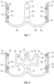
- FIG. 6 illustrates an embodiment of a valve frame 62 including a plurality of axially extending support arms 64, which may be coupled to a plurality of leaflets 68 (three valve leaflets 68 are shown in FIG. 6 ).
- Each support arm 64 may couple to the valve leaflets 68 at a commissure of the leaflets 68, or in another position as desired.
- Each support arm 64 may extend from a proximal end of the valve frame 62 to a distal end of the valve frame 62.
- Three support arms 64 may be provided, circumferentially spaced from each other at the commissures.
- the support arms 64 may be equally spaced from each other circumferentially.
- the valve frame 62 may include one or more circumferentially extending support arms 66 that may couple the axially extending support arms 64 to each other.
- the circumferentially extending support arms 66 may extend around the valve leaflets 68 at a base or distal portion of the valve leaflets 68, and may extend around the flow channel of the valve frame 62.
- the circumferentially extending support arms 66 may form an outer periphery of the valve frame 62. Openings may be otherwise positioned between the axially extending support arms 64, for instance the proximal ends of the arms 64.
- the valve frame 62 may have an outer surface and an inner surface and configured to dock to the docking frame 10 to support the valve frame within a portion of the patient's body.
- Three leaflets 68 may couple to the valve frame 62 and extend radially inward from the inner surface of the support arms 64 as shown, or a greater or lesser number of leaflets 68 may be utilized as desired.
- the valve frame 62 may be configured to be radially collapsed and radially expanded, and may be expanded radially outward from the axis that the valve frame 62 surrounds.
- the valve frame 62 may be configured such that a length of the valve frame 62 decreases as the width or diameter of the valve frame 62 increases, as disclosed herein.
- the valve frame 62 may include one or more connectors 70 that may be positioned on the axially extending support arms 64 or another portion of the valve frame 62 such as the circumferentially extending support arms 66.
- the connectors 70 may comprise openings as shown in FIG. 6 , or may have another configuration in another embodiment, such as pins, latches, or other connectors as desired.
- the connectors 70 may be utilized to dock the valve frame 62 to a docking frame 10 such as the docking frame shown in FIG. 1 .
- the docking frame 10 may be configured to have connectors 72 or the like.
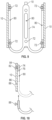
- FIG. 7 illustrates the docking frame 10 coupled to the valve frame 62 with connectors 72 in the form of pins extending through and engaging the connectors 70 of the valve frame 62.
- the docking frame 10 and valve frame 62 are shown in partial cross sectional view in FIG. 7 .
- the leaflets 68 and a third support arm 66 are not shown for clarity.
- the connectors 72, 70 may include a proximal connector and a distal connector, and engagement of the connectors 72, 70 may be provided at each of the support arms 64.
- the valve frame 62 and the docking frame 10 may be docked together by passing the connectors 70 of the docking frame 10 through the connectors 72 of the valve frame 62.
- the docking may occur prior to the valve frame 62 and docking frame 10 being inserted into the patient's body and external to the patient's body.
- pre-CT or other forms of visualization of the implantation site may occur.
- a user such as a medical clinician may thus determine the diameter of the portion of the patient's body to which the system will be deployed.
- the user may then select a desired size of the valve frame 62 from a selection of possible sizes of valve frames, in a manner as disclosed herein.
- the valve frame 62 selected may have a working diameter that fits the diameter of the portion of the patient's body to which the system will be deployed, and may be selected from a set of other valve frames having other working diameters, as disclosed herein.
- the user may then dock the selected valve frame 62 to the docking frame 10 via the connectors 72, 70.
- the docked valve frame 62 and docking frame 10 may then be inserted into the patient's body.
- the valve frame 62 may be deployed and radially expanded along with the docking frame 10, due to the coupling between the valve frame 62 and docking frame 10.
- the frames may be resisted from expanding axially by the shaped body 78 and thus may be resisted from being radially compressed (as radial compression may require axial expansion).
- the valve frame 74 accordingly may serve to resist radial compression of the frames, and secure the frames within the patient's body.
- valve frame 74 may be coupled to the docking frame 10 prior to insertion into the patient's body with only a partial connection of connectors 86, 88.
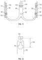
- FIG. 10 illustrates a side cross sectional view of a portion of the valve frame shown in FIGS. 8 and 9 comprising the support arm 76, and the docking frame 10 shown in FIGS. 8 and 9 .
- proximal connectors 82, 84 may couple to each other at a proximal end of the valve frame.
- Such proximal connectors 82, 84 may be engaged prior to insertion within the patient's body and external to the patient's body.
- Distal connectors 86, 88 may be unengaged prior to insertion.
- the valve frame may then expand, causing the connector 88 to relatively move axially towards to the connector 86 to engage the connector 86.
- FIG. 12 illustrates the axial position of the connectors 94, 102 prior to engagement.
- the docking frame 10 and the valve frame 92 may both be in a compressed state in FIG. 12 , prior to radial expansion. Due to radial expansion of the valve frame 92, the connector 94 moves axially towards to the connector 102 such that the connector 102 enters and is retained by the connector 94.
- the axial distance 104 between the connectors 102, 94 may be selected based on a desired amount of radial expansion of the valve frame 92. If a greater amount of expansion may be desired, then the connector 94 may be positioned further distal on the valve frame 92, and if a lesser amount of expansion is desired, then the connector 94 may be positioned further proximal on the valve frame 92.
- a valve frame 92 may be selected from a set of valve frames, each having a different axial position of a connector 94, which may correspond to a desired working diameter of the valve frame 92. The selection of the valve frame may occur from the set of valve frame according to methods disclosed herein.
- FIG. 13 illustrates an embodiment in which an axial distance 106 or length of axial movement of connectors 108, 110 may be set based on a length 112 of the connector 108.
- a valve frame 114 is shown in FIG. 13 positioned upon a docking frame 116.
- a plurality of leaflets 118 may be coupled to the valve frame 114 (one leaflet 118 is represented in FIG. 13 ).
- the valve frame 114 may include connectors 108 in the form of arms having latches at their ends that extend axially distal. The arms may extend axially within covers in the form of sleeves 120 of the docking frame 116.
- the connectors 108 may be relatively moved axially towards the connectors 110 on the docking frame 116 to engage the connectors 110.
- the length 112 of the connector 108 may be set according to the selected diameter of expansion for the valve frame 114.
- the length 112 of the arm of the connector 108 may define a diameter at which radial compression of the valve frame and docking frame may be resisted by the locking mechanism, and may be tailored based on the desired working diameter of expansion of the valve frame 114.
- Different valve frames having different diameters may accordingly be utilized with the same docking frame 116, with a resistance to radial compression being defined at a diameter set by the length 112 of the connector 108.
- the plurality of valve frames 114 may each have a connector 108 (such as an arm) that has a length that differs from each other and defines a diameter at which radial compression of the respective valve frame and the docking frame 116 is resisted.
- a connector 108 such as an arm
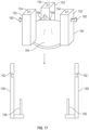
- FIG. 16 illustrates an embodiment in which a proximal portion of the valve frame 134 engages a proximal portion of the docking frame 136 via a connector 138 on the valve frame 134 in the form of an opening that receives a connector 140 on the docking frame 136 in the form of a pin.
- the engagement of the connection may be performed exterior to the patient's body, before implantation.
- the engagement of the connectors 142, 146 may occur within the patient's body upon expansion of the frames, as disclosed herein.
- the length of the connector 142 of the valve frame 134 may be set to provide a desired axial distance 144 or length of axial movement of the connectors 142, 146, as discussed herein.
- FIG. 17 illustrates an embodiment of a valve frame 150 in which the support arms 152 each include a connector 154 configured to axially slide upon a connector 156 in the form of a pin extending from a docking frame 158.
- the connectors 154 may comprise openings extending axially and configured to receive the pins.
- connectors 160 in the form of pins may engage connectors 162 in the form of openings in the docking frame 158.
- the valve frame 150 may be docked to the docking frame 158 by the connection of the connectors 154, 156, 160, 162 and the leaflets 164 may then operate upon deployment.
- the docking may occur exterior to the patient's body and prior to implantation as desired. In embodiments, the docking may occur within the patient's body.
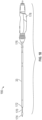
- FIG. 18 illustrates an embodiment of a delivery apparatus 166 that may be utilized according to embodiments herein.
- the delivery apparatus utilized may be varied in other embodiments.
- the delivery apparatus 166 may include the delivery shaft 33, which may include an implant retention area 170 that may retain one or more of the valve frame or docking frame.
- a sheath of the delivery shaft 33 may cover the docking frame or valve frame in the implant retention area 170.
- the implant retention area 170 may be positioned at a distal end 172 of the delivery shaft 33.
- a nosecone 174 (as marked in FIG. 1 ) may further be positioned at the distal end 172 of the delivery shaft 33.
- the delivery shaft 33 may include a proximal end 176 that may couple to a handle 178 utilized to grip the delivery apparatus 166, or may couple to another form of housing.
- prosthetic valve may be discussed in regard to a prosthetic valve, however, the systems, devices, and methods disclosed herein are not limited to prosthetic valves.
- Other forms of implants and prosthetic implants may utilize the systems, devices, and methods disclosed herein, including stents and other forms of medical implants.
- the systems, devices, and methods disclosed herein are not limited to treatment of the aortic valve, but may extend to mitral, pulmonary, and tricuspid valves, as well as treatment of other portions of a patient's body. Other uses may be provided.
- the implants may be cylindrical implants, or in other embodiments may have other shapes such as "V" shaped implants or other shapes as desired.
- the implants may be configured to expand radially outward from an axis that the implant surrounds, for example a longitudinal axis of the implant.
- the implants may be balloon expandable, mechanically expandable, or may be self-expanding in embodiments, unless otherwise indicated.
- the delivery apparatuses utilized, for example, may be configured to produce the desired form of expansion.
- the delivery apparatus may include an expansion balloon and may include a lumen for inflating and expanding the balloon positioned interior of the valve.
- the delivery apparatus may include a mechanical deployment mechanism for expanding the valve.
- the delivery apparatus may include a retractable sheath or the like for uncovering the valve and allowing the valve to expand.
- Other forms of deployment and delivery apparatuses may be utilized as desired.
- the connectors as disclosed herein may comprise one or more of a pin, a latch, or an opening, among other forms of connectors.
- the systems, devices, and methods disclosed herein may be used in a variety of procedures, which may include transcatheter aortic valve implantation (TAVI).
- TAVI transcatheter aortic valve implantation
- the delivery apparatus and the systems disclosed herein may be utilized for transarterial access, including transfemoral access, to a patient's heart.
- the approach to the delivery site may be in a variety of manners. For example, an approach to a native aortic valve may be through an aortic arch. In embodiments, a ventricular approach may be utilized, approaching the native aortic valve from the inflow side of the native aortic valve.
- the systems, devices, and method disclosed herein may be utilized for mitral, tricuspid, and pulmonary replacement and repair as well.
- the delivery systems may be utilized in transcatheter percutaneous procedures, including transarterial procedures, which may be transfemoral or transjugular. Transapical procedures, among others, may also be utilized.
- the methods herein are not limited to the methods specifically described, and may include methods of utilizing the systems and devices disclosed herein.
Landscapes
- Health & Medical Sciences (AREA)
- Engineering & Computer Science (AREA)
- Biomedical Technology (AREA)
- Cardiology (AREA)
- Oral & Maxillofacial Surgery (AREA)
- Transplantation (AREA)
- Heart & Thoracic Surgery (AREA)
- Vascular Medicine (AREA)
- Life Sciences & Earth Sciences (AREA)
- Animal Behavior & Ethology (AREA)
- General Health & Medical Sciences (AREA)
- Public Health (AREA)
- Veterinary Medicine (AREA)
- Prostheses (AREA)
Claims (13)
- Klappenprothesensystem, umfassend:einen Andockrahmen (10), der ausgestaltet ist, um innerhalb eines Abschnitts eines Körpers eines Patienten implantiert zu werden;einen Klappenrahmen (34) mit einer Außenoberfläche (42) und einer Innenoberfläche (44), und der ausgestaltet ist, um an den Andockrahmen anzudocken, um den Klappenrahmen innerhalb des Abschnitts des Körpers des Patienten zu halten;eine Vielzahl von Klappensegeln (48), die an den Klappenrahmen gekoppelt ist und ausgestaltet ist, um sich von der Innenoberfläche des Klappenrahmens radial einwärts zu erstrecken; undeinen Arretiermechanismus, der einen ersten Konnektor (94) auf dem Klappenrahmen und einen zweiten Konnektor (102) auf dem Andockrahmen einschließt, der ausgestaltet ist, um sich relativ axial in Richtung des ersten Konnektors zu bewegen, um in Eingriff mit dem ersten Konnektor zu kommen;wobei ein axialer Abstand (104) zwischen dem ersten Konnektor und dem zweiten Konnektor einen Durchmesser (56) definiert, bei dem durch den Arretiermechanismus radialer Kompression des Klappenrahmens und des Andockrahmens Widerstand entgegengesetzt wird; unddes Weiteren umfassend einen dritten Konnektor (100) auf dem Klappenrahmen und einen vierten Konnektor (98) auf dem Andockrahmen, wobei der dritte Konnektor und der vierte Konnektor ausgestaltet sind, um bei axialer Bewegung des zweiten Konnektors relativ zu dem ersten Konnektor in Eingriff miteinander zu bleiben.
- Klappenprothesensystem nach Anspruch 1, wobei der Andockrahmen ein mechanisch expandierbarer Rahmen ist.
- Klappenprothesensystem nach Anspruch 1 oder Anspruch 2, wobei der Andockrahmen radial expandierbar ist und der Klappenrahmen radial expandierbar ist und ein Arbeitsdurchmesserbereich des Andockrahmens größer als ein Arbeitsdurchmesserbereich des Klappenrahmens ist.
- Klappenprothesensystem nach einem der Ansprüche 1 bis 3, wobei der Andockrahmen radial expandierbar ist und der Klappenrahmen radial expandierbar ist, und ein größter Arbeitsdurchmesser (58) des Andockrahmens größer als ein größter Arbeitsdurchmesser des Klappenrahmens ist.
- Klappenprothesensystem nach einem der Ansprüche 1 bis 4, des Weiteren umfassend eine Vielzahl von Klappenrahmen, wobei jeder von der Vielzahl der Klappenrahmen einen anderen größten Arbeitsdurchmesser als jeder andere aufweist und ausgestaltet ist, um an den Andockrahmen anzudocken, um den jeweiligen Klappenrahmen innerhalb des Abschnitts des Körpers des Patienten zu halten, wobei eine Vielzahl von Klappensegeln (68) an den jeweiligen Klappenrahmen gekoppelt ist und ausgestaltet ist, um sich von einer Innenoberfläche (44) des jeweiligen Klappenrahmens radial einwärts zu erstrecken.
- Klappenprothesensystem nach einem der Ansprüche 1 bis 5, wobei der Klappenrahmen ausgestaltet ist, um innerhalb des Körpers des Patienten an den Andockrahmen angedockt zu werden.
- Klappenprothesensystem nach einem der Ansprüche 1 bis 6, wobei der Klappenrahmen eine Vielzahl sich axial erstreckender Haltearme (64) einschließt, die an die Vielzahl von Klappensegeln gekoppelt ist,
gegebenenfalls des Weiteren umfassend einen oder mehrere sich im Umfang erstreckende Haltearme (66), die die Vielzahl der sich axial erstreckenden Haltearme aneinander koppelt bzw. koppeln. - Klappenprothesensystem nach einem der Ansprüche 1 bis 7, wobei der Klappenrahmen selbstexpandierend ist und ausgestaltet ist, um radial auswärts zu expandieren.
- Klappenprothesensystem nach einem der vorhergehenden Ansprüche, wobei der zweite Konnektor (102) ausgestaltet ist, um sich relativ axial in Richtung des ersten Konnektors (94) zu bewegen, um aufgrund von radialer Expansion des Klappenrahmens in Eingriff mit dem ersten Konnektor zu kommen.
- Klappenprothesensystem nach einem der vorhergehenden Ansprüche, wobei:a.) der Arretiermechanismus ausgestaltet ist, um axialer Expansion des Andockrahmens Widerstand entgegenzusetzen; und/oderb.) der Arretiermechanismus ausgestaltet ist, um radialer Kompression des Klappenrahmens und des Andockrahmens Widerstand entgegenzusetzen; und/oderc.) der Arretiermechanismus radialer Expansion des Klappenrahmens über einen Durchmesser (56) hinaus Widerstand entgegensetzt.
- Klappenprothesensystem nach einem der vorhergehenden Ansprüche, wobei der erste Konnektor einen Arm einschließt, der sich axial (108) erstreckt, wobei eine Länge (112) des Arms einen Durchmesser definiert, bei dem der Arretiermechanismus radialer Kompression des Klappenrahmens und des Andockrahmens Widerstand entgegensetzt.
- Klappenprothesensystem nach einem der vorhergehenden Ansprüche, des Weiteren umfassend eine Vielzahl von Klappenrahmen, wobei jeder von der Vielzahl der Klappenrahmen einen Konnektor einschließt, der einen Arm (108) aufweist, der ausgestaltet ist, um sich relativ axial in Richtung des zweiten Konnektors (110) zu bewegen, um in Eingriff mit dem zweiten Konnektor zu kommen, wobei jeder jeweilige Arm eine Länge (112) aufweist, die sich von derjenigen der jeweiligen anderen unterscheidet, und die einen Durchmesser definiert, bei der radialer Kompression des jeweiligen Klappenrahmens und des Andockrahmens Widerstand entgegengesetzt wird.
- Klappenprothesensystem nach einem der vorhergehenden Ansprüche, wobei der erste Konnektor oder der zweite Konnektor ein oder mehrere von einem Stift (160), einer Verriegelung oder einer Öffnung (162) umfassen.
Priority Applications (1)
| Application Number | Priority Date | Filing Date | Title |
|---|---|---|---|
| EP25161537.3A EP4591830A3 (de) | 2020-06-23 | 2021-06-22 | Prothesenimplantatsysteme zur durchmesseranpassung |
Applications Claiming Priority (2)
| Application Number | Priority Date | Filing Date | Title |
|---|---|---|---|
| US202063042734P | 2020-06-23 | 2020-06-23 | |
| PCT/US2021/038420 WO2021262678A1 (en) | 2020-06-23 | 2021-06-22 | Prosthetic implant systems for diameter adaptation |
Related Child Applications (1)
| Application Number | Title | Priority Date | Filing Date |
|---|---|---|---|
| EP25161537.3A Division EP4591830A3 (de) | 2020-06-23 | 2021-06-22 | Prothesenimplantatsysteme zur durchmesseranpassung |
Publications (2)
| Publication Number | Publication Date |
|---|---|
| EP4138734A1 EP4138734A1 (de) | 2023-03-01 |
| EP4138734B1 true EP4138734B1 (de) | 2025-03-05 |
Family
ID=77022200
Family Applications (2)
| Application Number | Title | Priority Date | Filing Date |
|---|---|---|---|
| EP25161537.3A Pending EP4591830A3 (de) | 2020-06-23 | 2021-06-22 | Prothesenimplantatsysteme zur durchmesseranpassung |
| EP21745498.2A Active EP4138734B1 (de) | 2020-06-23 | 2021-06-22 | Prothesenimplantatsysteme zur durchmesseranpassung |
Family Applications Before (1)
| Application Number | Title | Priority Date | Filing Date |
|---|---|---|---|
| EP25161537.3A Pending EP4591830A3 (de) | 2020-06-23 | 2021-06-22 | Prothesenimplantatsysteme zur durchmesseranpassung |
Country Status (7)
| Country | Link |
|---|---|
| US (1) | US20230113498A1 (de) |
| EP (2) | EP4591830A3 (de) |
| JP (1) | JP2023532447A (de) |
| CN (1) | CN115715175A (de) |
| CA (1) | CA3185155A1 (de) |
| ES (1) | ES3031166T3 (de) |
| WO (1) | WO2021262678A1 (de) |
Family Cites Families (6)
| Publication number | Priority date | Publication date | Assignee | Title |
|---|---|---|---|---|
| JP4842144B2 (ja) * | 2003-12-23 | 2011-12-21 | サドラ・メディカル・インコーポレーテッド | 再配備可能な心臓弁 |
| JP4912395B2 (ja) * | 2005-05-24 | 2012-04-11 | エドワーズ ライフサイエンシーズ コーポレイション | 迅速配置式補綴用心臓弁 |
| US20080004696A1 (en) * | 2006-06-29 | 2008-01-03 | Valvexchange Inc. | Cardiovascular valve assembly with resizable docking station |
| US9566178B2 (en) | 2010-06-24 | 2017-02-14 | Edwards Lifesciences Cardiaq Llc | Actively controllable stent, stent graft, heart valve and method of controlling same |
| JP6503454B2 (ja) * | 2014-05-09 | 2019-04-17 | フォルダックス, インコーポレイテッド | 置換用心臓弁ならびにそれらの使用および製造の方法 |
| US10363130B2 (en) * | 2016-02-05 | 2019-07-30 | Edwards Lifesciences Corporation | Devices and systems for docking a heart valve |
-
2021
- 2021-06-22 EP EP25161537.3A patent/EP4591830A3/de active Pending
- 2021-06-22 ES ES21745498T patent/ES3031166T3/es active Active
- 2021-06-22 WO PCT/US2021/038420 patent/WO2021262678A1/en not_active Ceased
- 2021-06-22 JP JP2022579827A patent/JP2023532447A/ja active Pending
- 2021-06-22 CA CA3185155A patent/CA3185155A1/en active Pending
- 2021-06-22 CN CN202180043236.1A patent/CN115715175A/zh active Pending
- 2021-06-22 EP EP21745498.2A patent/EP4138734B1/de active Active
-
2022
- 2022-12-13 US US18/065,257 patent/US20230113498A1/en active Pending
Also Published As
| Publication number | Publication date |
|---|---|
| ES3031166T3 (en) | 2025-07-04 |
| CN115715175A (zh) | 2023-02-24 |
| EP4591830A2 (de) | 2025-07-30 |
| JP2023532447A (ja) | 2023-07-28 |
| CA3185155A1 (en) | 2021-12-30 |
| WO2021262678A1 (en) | 2021-12-30 |
| EP4138734A1 (de) | 2023-03-01 |
| US20230113498A1 (en) | 2023-04-13 |
| EP4591830A3 (de) | 2025-10-22 |
Similar Documents
| Publication | Publication Date | Title |
|---|---|---|
| US20240081990A1 (en) | Heart valve prostheses including torque anchoring mechanisms and delivery devices for the heart valve prostheses | |
| US11007054B2 (en) | Subannular sealing for paravalvular leak protection | |
| EP2919712B1 (de) | Anordnung zum einsetzen einer klappenprothese | |
| US20090287290A1 (en) | Delivery Systems and Methods of Implantation for Prosthetic Heart Valves | |
| EP2979664B1 (de) | Aortenklappenprothese, insbesondere zur Transkatheterimplantation | |
| US20180098846A1 (en) | Delivery System for a Valve Prosthesis | |
| US20250017726A1 (en) | Adjustable leaflet assemblies for expandable prosthetic heart valves | |
| US20250073030A1 (en) | Outer skirt for an expandable prosthetic heart valve | |
| US20240299164A1 (en) | Prosthetic valve delivery apparatus with strain relief nosecone | |
| US20230113498A1 (en) | Prosthetic implant systems for diameter adaptation | |
| EP3988052B1 (de) | Passive ausrichtung von kommissuren bei der implantation von herzklappenprothesen | |
| US20250169948A1 (en) | Commissure Alignment for Transcatheter Prosthetic Heart Valves | |
| US20250120806A1 (en) | Balloon expandable commissure attachment features | |
| US20250064587A1 (en) | TAVI Deployment Accuracy - Measures to Direct Balloon Inflation | |
| WO2025160107A1 (en) | Systems and methods for aligning a commissure of a prosthetic valve with a commissure of a native valve | |
| WO2026062630A1 (en) | Cardiac anchoring stent, valve system and a method for deploying same |
Legal Events
| Date | Code | Title | Description |
|---|---|---|---|
| STAA | Information on the status of an ep patent application or granted ep patent |
Free format text: STATUS: UNKNOWN |
|
| STAA | Information on the status of an ep patent application or granted ep patent |
Free format text: STATUS: THE INTERNATIONAL PUBLICATION HAS BEEN MADE |
|
| PUAI | Public reference made under article 153(3) epc to a published international application that has entered the european phase |
Free format text: ORIGINAL CODE: 0009012 |
|
| STAA | Information on the status of an ep patent application or granted ep patent |
Free format text: STATUS: REQUEST FOR EXAMINATION WAS MADE |
|
| 17P | Request for examination filed |
Effective date: 20221124 |
|
| AK | Designated contracting states |
Kind code of ref document: A1 Designated state(s): AL AT BE BG CH CY CZ DE DK EE ES FI FR GB GR HR HU IE IS IT LI LT LU LV MC MK MT NL NO PL PT RO RS SE SI SK SM TR |
|
| P01 | Opt-out of the competence of the unified patent court (upc) registered |
Effective date: 20230529 |
|
| DAV | Request for validation of the european patent (deleted) | ||
| DAX | Request for extension of the european patent (deleted) | ||
| STAA | Information on the status of an ep patent application or granted ep patent |
Free format text: STATUS: EXAMINATION IS IN PROGRESS |
|
| 17Q | First examination report despatched |
Effective date: 20231123 |
|
| GRAP | Despatch of communication of intention to grant a patent |
Free format text: ORIGINAL CODE: EPIDOSNIGR1 |
|
| STAA | Information on the status of an ep patent application or granted ep patent |
Free format text: STATUS: GRANT OF PATENT IS INTENDED |
|
| INTG | Intention to grant announced |
Effective date: 20241002 |
|
| GRAS | Grant fee paid |
Free format text: ORIGINAL CODE: EPIDOSNIGR3 |
|
| GRAA | (expected) grant |
Free format text: ORIGINAL CODE: 0009210 |
|
| STAA | Information on the status of an ep patent application or granted ep patent |
Free format text: STATUS: THE PATENT HAS BEEN GRANTED |
|
| AK | Designated contracting states |
Kind code of ref document: B1 Designated state(s): AL AT BE BG CH CY CZ DE DK EE ES FI FR GB GR HR HU IE IS IT LI LT LU LV MC MK MT NL NO PL PT RO RS SE SI SK SM TR |
|
| REG | Reference to a national code |
Ref country code: GB Ref legal event code: FG4D |
|
| REG | Reference to a national code |
Ref country code: CH Ref legal event code: EP |
|
| REG | Reference to a national code |
Ref country code: IE Ref legal event code: FG4D |
|
| REG | Reference to a national code |
Ref country code: DE Ref legal event code: R096 Ref document number: 602021027186 Country of ref document: DE |
|
| REG | Reference to a national code |
Ref country code: NL Ref legal event code: FP |
|
| REG | Reference to a national code |
Ref country code: ES Ref legal event code: FG2A Ref document number: 3031166 Country of ref document: ES Kind code of ref document: T3 Effective date: 20250704 |
|
| PG25 | Lapsed in a contracting state [announced via postgrant information from national office to epo] |
Ref country code: RS Free format text: LAPSE BECAUSE OF FAILURE TO SUBMIT A TRANSLATION OF THE DESCRIPTION OR TO PAY THE FEE WITHIN THE PRESCRIBED TIME-LIMIT Effective date: 20250605 |
|
| PG25 | Lapsed in a contracting state [announced via postgrant information from national office to epo] |
Ref country code: FI Free format text: LAPSE BECAUSE OF FAILURE TO SUBMIT A TRANSLATION OF THE DESCRIPTION OR TO PAY THE FEE WITHIN THE PRESCRIBED TIME-LIMIT Effective date: 20250305 |
|
| REG | Reference to a national code |
Ref country code: LT Ref legal event code: MG9D |
|
| PG25 | Lapsed in a contracting state [announced via postgrant information from national office to epo] |
Ref country code: NO Free format text: LAPSE BECAUSE OF FAILURE TO SUBMIT A TRANSLATION OF THE DESCRIPTION OR TO PAY THE FEE WITHIN THE PRESCRIBED TIME-LIMIT Effective date: 20250605 |
|
| PG25 | Lapsed in a contracting state [announced via postgrant information from national office to epo] |
Ref country code: HR Free format text: LAPSE BECAUSE OF FAILURE TO SUBMIT A TRANSLATION OF THE DESCRIPTION OR TO PAY THE FEE WITHIN THE PRESCRIBED TIME-LIMIT Effective date: 20250305 |
|
| PG25 | Lapsed in a contracting state [announced via postgrant information from national office to epo] |
Ref country code: LV Free format text: LAPSE BECAUSE OF FAILURE TO SUBMIT A TRANSLATION OF THE DESCRIPTION OR TO PAY THE FEE WITHIN THE PRESCRIBED TIME-LIMIT Effective date: 20250305 |
|
| PG25 | Lapsed in a contracting state [announced via postgrant information from national office to epo] |
Ref country code: GR Free format text: LAPSE BECAUSE OF FAILURE TO SUBMIT A TRANSLATION OF THE DESCRIPTION OR TO PAY THE FEE WITHIN THE PRESCRIBED TIME-LIMIT Effective date: 20250606 Ref country code: BG Free format text: LAPSE BECAUSE OF FAILURE TO SUBMIT A TRANSLATION OF THE DESCRIPTION OR TO PAY THE FEE WITHIN THE PRESCRIBED TIME-LIMIT Effective date: 20250305 |
|
| REG | Reference to a national code |
Ref country code: AT Ref legal event code: MK05 Ref document number: 1772215 Country of ref document: AT Kind code of ref document: T Effective date: 20250305 |
|
| PG25 | Lapsed in a contracting state [announced via postgrant information from national office to epo] |
Ref country code: SE Free format text: LAPSE BECAUSE OF FAILURE TO SUBMIT A TRANSLATION OF THE DESCRIPTION OR TO PAY THE FEE WITHIN THE PRESCRIBED TIME-LIMIT Effective date: 20250305 |
|
| PG25 | Lapsed in a contracting state [announced via postgrant information from national office to epo] |
Ref country code: SM Free format text: LAPSE BECAUSE OF FAILURE TO SUBMIT A TRANSLATION OF THE DESCRIPTION OR TO PAY THE FEE WITHIN THE PRESCRIBED TIME-LIMIT Effective date: 20250305 |
|
| PG25 | Lapsed in a contracting state [announced via postgrant information from national office to epo] |
Ref country code: PT Free format text: LAPSE BECAUSE OF FAILURE TO SUBMIT A TRANSLATION OF THE DESCRIPTION OR TO PAY THE FEE WITHIN THE PRESCRIBED TIME-LIMIT Effective date: 20250707 |
|
| PG25 | Lapsed in a contracting state [announced via postgrant information from national office to epo] |
Ref country code: PL Free format text: LAPSE BECAUSE OF FAILURE TO SUBMIT A TRANSLATION OF THE DESCRIPTION OR TO PAY THE FEE WITHIN THE PRESCRIBED TIME-LIMIT Effective date: 20250305 |
|
| PG25 | Lapsed in a contracting state [announced via postgrant information from national office to epo] |
Ref country code: AT Free format text: LAPSE BECAUSE OF FAILURE TO SUBMIT A TRANSLATION OF THE DESCRIPTION OR TO PAY THE FEE WITHIN THE PRESCRIBED TIME-LIMIT Effective date: 20250305 |
|
| PG25 | Lapsed in a contracting state [announced via postgrant information from national office to epo] |
Ref country code: CZ Free format text: LAPSE BECAUSE OF FAILURE TO SUBMIT A TRANSLATION OF THE DESCRIPTION OR TO PAY THE FEE WITHIN THE PRESCRIBED TIME-LIMIT Effective date: 20250305 Ref country code: EE Free format text: LAPSE BECAUSE OF FAILURE TO SUBMIT A TRANSLATION OF THE DESCRIPTION OR TO PAY THE FEE WITHIN THE PRESCRIBED TIME-LIMIT Effective date: 20250305 |
|
| PG25 | Lapsed in a contracting state [announced via postgrant information from national office to epo] |
Ref country code: RO Free format text: LAPSE BECAUSE OF FAILURE TO SUBMIT A TRANSLATION OF THE DESCRIPTION OR TO PAY THE FEE WITHIN THE PRESCRIBED TIME-LIMIT Effective date: 20250305 |
|
| PG25 | Lapsed in a contracting state [announced via postgrant information from national office to epo] |
Ref country code: SK Free format text: LAPSE BECAUSE OF FAILURE TO SUBMIT A TRANSLATION OF THE DESCRIPTION OR TO PAY THE FEE WITHIN THE PRESCRIBED TIME-LIMIT Effective date: 20250305 |
|
| PG25 | Lapsed in a contracting state [announced via postgrant information from national office to epo] |
Ref country code: IS Free format text: LAPSE BECAUSE OF FAILURE TO SUBMIT A TRANSLATION OF THE DESCRIPTION OR TO PAY THE FEE WITHIN THE PRESCRIBED TIME-LIMIT Effective date: 20250705 |
|
| REG | Reference to a national code |
Ref country code: DE Ref legal event code: R097 Ref document number: 602021027186 Country of ref document: DE |
|
| PLBE | No opposition filed within time limit |
Free format text: ORIGINAL CODE: 0009261 |
|
| STAA | Information on the status of an ep patent application or granted ep patent |
Free format text: STATUS: NO OPPOSITION FILED WITHIN TIME LIMIT |
|
| PG25 | Lapsed in a contracting state [announced via postgrant information from national office to epo] |
Ref country code: DK Free format text: LAPSE BECAUSE OF FAILURE TO SUBMIT A TRANSLATION OF THE DESCRIPTION OR TO PAY THE FEE WITHIN THE PRESCRIBED TIME-LIMIT Effective date: 20250305 |
|
| REG | Reference to a national code |
Ref country code: CH Ref legal event code: L10 Free format text: ST27 STATUS EVENT CODE: U-0-0-L10-L00 (AS PROVIDED BY THE NATIONAL OFFICE) Effective date: 20260114 |
|
| REG | Reference to a national code |
Ref country code: CH Ref legal event code: H13 Free format text: ST27 STATUS EVENT CODE: U-0-0-H10-H13 (AS PROVIDED BY THE NATIONAL OFFICE) Effective date: 20260127 |
|
| PG25 | Lapsed in a contracting state [announced via postgrant information from national office to epo] |
Ref country code: MC Free format text: LAPSE BECAUSE OF FAILURE TO SUBMIT A TRANSLATION OF THE DESCRIPTION OR TO PAY THE FEE WITHIN THE PRESCRIBED TIME-LIMIT Effective date: 20250305 |
|
| REG | Reference to a national code |
Ref country code: NL Ref legal event code: MM Effective date: 20250701 |
|
| 26N | No opposition filed |
Effective date: 20251208 |
|
| PG25 | Lapsed in a contracting state [announced via postgrant information from national office to epo] |
Ref country code: LU Free format text: LAPSE BECAUSE OF NON-PAYMENT OF DUE FEES Effective date: 20250622 |
|
| REG | Reference to a national code |
Ref country code: BE Ref legal event code: MM Effective date: 20250630 |
|
| PG25 | Lapsed in a contracting state [announced via postgrant information from national office to epo] |
Ref country code: NL Free format text: LAPSE BECAUSE OF NON-PAYMENT OF DUE FEES Effective date: 20250701 |
|
| PG25 | Lapsed in a contracting state [announced via postgrant information from national office to epo] |
Ref country code: IE Free format text: LAPSE BECAUSE OF NON-PAYMENT OF DUE FEES Effective date: 20250622 |
|
| PG25 | Lapsed in a contracting state [announced via postgrant information from national office to epo] |
Ref country code: BE Free format text: LAPSE BECAUSE OF NON-PAYMENT OF DUE FEES Effective date: 20250630 Ref country code: IT Free format text: LAPSE BECAUSE OF NON-PAYMENT OF DUE FEES Effective date: 20250622 |
|
| PG25 | Lapsed in a contracting state [announced via postgrant information from national office to epo] |
Ref country code: FR Free format text: LAPSE BECAUSE OF NON-PAYMENT OF DUE FEES Effective date: 20250630 |
|
| PG25 | Lapsed in a contracting state [announced via postgrant information from national office to epo] |
Ref country code: CH Free format text: LAPSE BECAUSE OF NON-PAYMENT OF DUE FEES Effective date: 20250630 |
|
| PG25 | Lapsed in a contracting state [announced via postgrant information from national office to epo] |
Ref country code: LT Free format text: LAPSE BECAUSE OF FAILURE TO SUBMIT A TRANSLATION OF THE DESCRIPTION OR TO PAY THE FEE WITHIN THE PRESCRIBED TIME-LIMIT Effective date: 20250305 |
|
| PGFP | Annual fee paid to national office [announced via postgrant information from national office to epo] |
Ref country code: GB Payment date: 20260408 Year of fee payment: 6 |
|
| PGFP | Annual fee paid to national office [announced via postgrant information from national office to epo] |
Ref country code: DE Payment date: 20260331 Year of fee payment: 6 |
|
| REG | Reference to a national code |
Ref country code: ES Ref legal event code: FD2A Effective date: 20260727 |
|
| PG25 | Lapsed in a contracting state [announced via postgrant information from national office to epo] |
Ref country code: CY Free format text: LAPSE BECAUSE OF FAILURE TO SUBMIT A TRANSLATION OF THE DESCRIPTION OR TO PAY THE FEE WITHIN THE PRESCRIBED TIME-LIMIT Effective date: 20250305 |