EP4138539B1 - Verfahren zur messung von ernteguteigenschaften - Google Patents
Verfahren zur messung von ernteguteigenschaften Download PDFInfo
- Publication number
- EP4138539B1 EP4138539B1 EP21715335.2A EP21715335A EP4138539B1 EP 4138539 B1 EP4138539 B1 EP 4138539B1 EP 21715335 A EP21715335 A EP 21715335A EP 4138539 B1 EP4138539 B1 EP 4138539B1
- Authority
- EP
- European Patent Office
- Prior art keywords
- measuring
- crop material
- volume
- crop
- electric field
- Prior art date
- Legal status (The legal status is an assumption and is not a legal conclusion. Google has not performed a legal analysis and makes no representation as to the accuracy of the status listed.)
- Active
Links
Images


Classifications
-
- A—HUMAN NECESSITIES
- A01—AGRICULTURE; FORESTRY; ANIMAL HUSBANDRY; HUNTING; TRAPPING; FISHING
- A01D—HARVESTING; MOWING
- A01D41/00—Combines, i.e. harvesters or mowers combined with threshing devices
- A01D41/12—Details of combines
- A01D41/127—Control or measuring arrangements specially adapted for combines
- A01D41/1271—Control or measuring arrangements specially adapted for combines for measuring crop flow
-
- G—PHYSICS
- G01—MEASURING; TESTING
- G01N—INVESTIGATING OR ANALYSING MATERIALS BY DETERMINING THEIR CHEMICAL OR PHYSICAL PROPERTIES
- G01N27/00—Investigating or analysing materials by the use of electric, electrochemical, or magnetic means
- G01N27/60—Investigating or analysing materials by the use of electric, electrochemical, or magnetic means by investigating electrostatic variables, e.g. electrographic flaw testing
- G01N27/605—Investigating or analysing materials by the use of electric, electrochemical, or magnetic means by investigating electrostatic variables, e.g. electrographic flaw testing for determining moisture content, e.g. humidity
-
- A—HUMAN NECESSITIES
- A01—AGRICULTURE; FORESTRY; ANIMAL HUSBANDRY; HUNTING; TRAPPING; FISHING
- A01D—HARVESTING; MOWING
- A01D34/00—Mowers; Mowing apparatus of harvesters
- A01D34/006—Control or measuring arrangements
-
- A—HUMAN NECESSITIES
- A01—AGRICULTURE; FORESTRY; ANIMAL HUSBANDRY; HUNTING; TRAPPING; FISHING
- A01D—HARVESTING; MOWING
- A01D43/00—Mowers combined with apparatus performing additional operations while mowing
- A01D43/08—Mowers combined with apparatus performing additional operations while mowing with means for cutting up the mown crop, e.g. forage harvesters
- A01D43/085—Control or measuring arrangements specially adapted therefor
-
- G—PHYSICS
- G01—MEASURING; TESTING
- G01F—MEASURING VOLUME, VOLUME FLOW, MASS FLOW OR LIQUID LEVEL; METERING BY VOLUME
- G01F1/00—Measuring the volume flow or mass flow of fluid or fluent solid material wherein the fluid passes through a meter in a continuous flow
- G01F1/76—Devices for measuring mass flow of a fluid or a fluent solid material
- G01F1/86—Indirect mass flowmeters, e.g. measuring volume flow and density, temperature or pressure
-
- G—PHYSICS
- G01—MEASURING; TESTING
- G01N—INVESTIGATING OR ANALYSING MATERIALS BY DETERMINING THEIR CHEMICAL OR PHYSICAL PROPERTIES
- G01N27/00—Investigating or analysing materials by the use of electric, electrochemical, or magnetic means
- G01N27/02—Investigating or analysing materials by the use of electric, electrochemical, or magnetic means by investigating impedance
- G01N27/22—Investigating or analysing materials by the use of electric, electrochemical, or magnetic means by investigating impedance by investigating capacitance
- G01N27/223—Investigating or analysing materials by the use of electric, electrochemical, or magnetic means by investigating impedance by investigating capacitance for determining moisture content, e.g. humidity
Definitions
- Embodiments of the present disclosure relate generally to machines and methods of harvesting crops.
- embodiments relate to methods and apparatus for determining the properties of harvested crops.
- Windrowers and other self-propelled harvesters have long been used to harvest crops for hay and forage.
- a conventional windrower includes a laterally extending header supported by a windrower chassis. As the windrower is advanced through a field, the header severs a swath of standing forage plants, such as grasses, alfalfa, wheat, etc. The header also collects the severed forage material and discharges the material rearwardly onto the ground in the form of a windrow extending behind the windrower.
- Windrowers can employ different types of headers, including sickle headers and rotating disc headers.
- the windrow is typically allowed to dry for a period of time, after which the crop is collected and baled.
- Various factors affect how quickly the cut crop material dries, such as crop moisture, ground moisture, windrow dimensions and density, and crop crimping.
- the crop should be baled when moisture levels are within certain ranges (which vary by the type of crop). Moisture levels too high can lead to mold or other damage during storage, whereas moisture levels too low can cause excess nutrient loss before baling and difficulty forming coherent bales.
- the present invention provides a method of measuring properties of a harvested crop according to claim 1 and a non-transitory computer-readable storage medium according to claim 14. Further aspects of the invention are defined in the dependent claims.
- the terms “comprising,” “including,” “containing,” “characterized by,” and grammatical equivalents thereof are inclusive or open-ended terms that do not exclude additional, unrecited elements or method steps, but also include the more restrictive terms “consisting of” and “consisting essentially of” and grammatical equivalents thereof.
- the term “configured” refers to a size, shape, material composition, and arrangement of one or more of at least one structure and at least one apparatus facilitating operation of one or more of the structure and the apparatus in a predetermined way.
- spatially relative terms such as “beneath,” “below,” “lower,” “bottom,” “above,” “upper,” “top,” “front,” “rear,” “left,” “right,” and the like, may be used for ease of description to describe one element's or feature's relationship to another element(s) or feature(s) as illustrated in the figures. Unless otherwise specified, the spatially relative terms are intended to encompass different orientations of the materials in addition to the orientation depicted in the figures.
- the term "substantially" in reference to a given parameter, property, or condition means and includes to a degree that one of ordinary skill in the art would understand that the given parameter, property, or condition is met with a degree of variance, such as within acceptable manufacturing tolerances.
- the parameter, property, or condition may be at least 90.0% met, at least 95.0% met, at least 99.0% met, or even at least 99.9% met.
- the term "about” used in reference to a given parameter is inclusive of the stated value and has the meaning dictated by the context (e.g., it includes the degree of error associated with measurement of the given parameter).
- FIG. 1 is a simplified diagram illustrating a device and method for measuring a harvested crop.
- crop material 102 may be laying on a ground surface 104.
- the crop material 102 may be laying or traveling on a surface of a machine (e.g., a baler, a combine harvester, etc. ).
- the crop material 102 may be measured as it is being cut.
- a measuring device 106 measures an attribute of an electric field 108 that interacts with the crop material 102.
- the measuring device 106 is within or carried by a frame 110 of an agricultural machine, such as a windrower, a baler, a combine harvester, a harvesting header, etc.
- the measuring device 106 may itself generate the electric field 108 and may be operable to change the electric field 108.
- the electric field 108 has a response curve, i.e., its attributes vary in a particular way in response to different conditions.
- the electric field 108 may have a field strength that decreases in proportion to 1/r 2 or 1/r 3 , where r is the distance from the measuring device 106.
- the presence of the crop material 102 may change a measurable attribute of the electric field 108.
- the electric field 108 is formed by electromagnetic radiation having a frequency that excites water molecules, moisture within the crop material 102 can affect the field lines of the electric field 108.
- the shape of the field lines may be the measurable attribute of the electric field 108, which may be detected by the measuring device 106.
- a change in the amount of moisture in the crop material 102-or a change in the amount (mass) of crop material 102- may change the shape of the field lines.
- the crop material 102 may cause a change in the electrical load provided by the measuring device 106 to generate the electric field 108.
- the total moisture in the measurement volume can be detected based on the measured attribute of the electric field 108. However, without additional information, neither the mass of the crop material 102 nor the moisture content of the crop material 102 can be determined from the total moisture.
- the measuring device 106 may generate a second electric field 208, as shown in FIG. 2 , which may have a different volume than the electric field 108 (or, if both fields 108, 208 are theoretically boundless, the second electric field 208 may have a different response curve). That is, even with the same amount and type of crop material 102 in the volume near the measuring device 106, the electric field 208 in FIG. 2 may nonetheless be different than the electric field 108 shown in FIG. 1 .
- the electric field 208 may vary based on a different variable (or combination of variables) than the electric field 108. For example, the shape of the field lines of the electric field 208 may vary based on the mass of the crop material 102 in the electric field 208.
- the measuring device 106 may detect two different variables, and these two variables may be used to determine two different properties of the crop material 102. If two different properties of the crop material 102 are calculated, confidence in the accuracy of the properties (or at least in one of the properties) is increased.
- the measuring device 106 may measure attributes of any number of electric fields. By determining additional independent attributes, other variables may be determined or derived, even if the variables are dependent on one or more of the variables already determined. Interrelated variables may generally be determined with sufficient independent information (e.g ., three independent variables may be used to determine three different properties). Determination of mass and total moisture in the electric fields 108, 208 may be combined with a ground speed of the machine or linear speed of the crop material 102 to determine mass flow and total moisture flow. Other properties that may be determined include, for example, the position of a top surface of the crop material 102 relative to the frame 110, a thickness of the crop material 102, and a density of the crop material 102.
- the electric field 108 may be formed by a transmitter powered by a power source within the measuring device 106. If the crop material 102 within the electric field 108 changes, the amount of power transmitted, and the amount of power drawn from the power source, may change. Thus, the measuring device 106 may measure the power draw to correlate to the property of the crop material 102. In some embodiments, the attributes of electric fields 108, 208 may be measured by measuring permittivity of the crop material 102.
- the crop material 102 may be measured as it is harvested by an agricultural machine, meaning that the crop material 102 is cut shortly before or as the measuring device 106 passes the electric field 108 near the crop material 102. In some embodiments, the crop material 102 may be measured before being cut.
- the crop material 102 is described herein as being “within the electric field,” a person having ordinary skill in the art will understand that electric fields are theoretically infinite, decaying to smaller field strength as distance increases.
- the term “within the electric field” herein means within a preselected volume relevant to the electric field, which may be defined by a threshold field strength, physical space boundaries, etc.
- FIGS. 3 and 4 illustrate another measuring device 306 that may be used for measuring a harvested crop 102.
- the measuring device 306 may be within or carried by a frame 110 of an agricultural machine.
- the measuring device 306 may contain a plurality of electrodes 312 arranged in an array (e.g., a linear or planar array).
- FIGS. 3 and 4 depict a measuring device 306 having seven electrodes 312a-312g in a linear array, though another number of electrodes 312 may be used.
- the electrodes 312 may be connected to a power source such that an electric field having field lines 308 forms between and adjacent to the electrodes 312 and the surroundings.
- the center electrode 312d is an electrical sink
- each adjacent electrode 312c, 312e is an electrical source.
- the remaining electrodes 312a, 312b, 312f, and 312g are grounded.
- some field lines 308 connect the electrical sources to the electrical sink
- other field lines 308 connect the shielding electrodes 312a, 312b, 312f, and 312g to one another or to ground.
- the field lines 308 associated with the shielding electrodes 312a, 312b, 312f, and 312g shield the electrical sources and the electrical sink limit the effects of material within those field lines 308.
- the hatched area in FIG. 3 indicates a measurement volume 320 in which material can affect the field lines 308 related to the electrical sources and electrical sink.
- the material within the measurement volume 320 can affect the magnitude of electric current flowing from the electrical sources to the electrical sink, and the material within a shielded volume 322 ( i.e., the area not hatched in FIG. 3 ) cannot.
- the measuring device 306 may include a measurement of the current flow from the electrical sources to the electrical sink. As the properties of the material within the measurement volume 320 changes, so too may the current. For example, the measuring device 306 may measure a resonant frequency of crop material within the measurement volume 320. As the crop material therein changes, the resonant frequency may change or "drift," which is associated with different physical properties of the crop material. Note that the crop material 102 is omitted from view in FIG. 3 for clarity, as is the ground surface 104 (see FIG. 1 ).
- FIG. 4 illustrates the same measuring device 306, in which electrical connections of some electrodes 312 have been changed.
- the center electrode 312d is an electrical sink
- the outermost electrodes 312a, 312g are electrical sources.
- the remaining electrodes 312b, 312c, 312e, and 312f are grounded.
- an electric field having field lines 408 forms between and adjacent to the electrodes 312 and the surroundings.
- Some field lines 408 connect the electrical sources to the electrical sink, and other field lines 408 connect the shielding electrodes 312b, 312c, 312e, and 312f to one another.
- the hatched area in FIG. 4 indicates a measurement volume 420 (extending theoretically to infinity) in which material can affect the field lines related to the electrical sources and electrical sink.
- the material within the measurement volume 420 can affect the magnitude of electric current flowing from the electrical sources to the electrical sink, and the material within a shielded volume 422 ( i.e., the area not hatched in FIG. 4 ) cannot.
- the measuring device 306 may be configurable to yield two different properties of the material therein without physically moving or changing the measuring device 306 or the material flow. These two properties may be used to calculate physical properties relevant to operation of the agricultural machine carrying the measuring device 306.
- the volume 420 is different from the volume 320, but may partially overlap. That is, some points may be within both the volume 320 and the volume 420, and other points may be within one volume 320, 420, but not the other.
- a larger volume in which crop material is measured may be the sum of two or more smaller volumes, and one of the smaller volumes may be measured separately for comparison.
- the shaded volume 320 may be the smaller volume, and the entire volume below the frame 110 may be the larger volume.
- the shaded volume 420 may be the smaller volume, and the entire volume below the frame 110 may be the larger volume.
- the volume in which crop material 102 is measured may be coextensive with different electric fields.
- the measuring device 106 may measure crop material 102 in a certain predefined volume with both fields, though the fields may have different field lines 108, 208.
- FIGS. 1 and 2 illustrate one way the measuring device 106 may be used to measure a material property of the crop material 102 by measuring signal attenuation or apparent load on the measuring device 106. That is, the measuring device 106 transmits a signal to generate the electric field, and measures the power output, which may vary based on a property ( e.g ., permittivity) of the crop material 102 in the field.
- FIGS. 3 and 4 illustrate one way the measuring device 306 may be used to measure received signal strength, resonant frequency, and/or frequency drift as a measure of a material property.
- Other measuring devices may use other parameters, such as capacitance, as a measure of material properties, and multiple of such other parameters may likewise be used to determine multiple physical properties of crop material, even if those physical properties are interrelated.
- combinations of sensors may be used to measure additional properties.
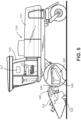
- FIG. 5 is a simplified side view of an example self-propelled windrower 510.
- the windrower 510 broadly includes a self-propelled tractor 512 and a harvesting header 514 attached to and carried by the front of the tractor 512.
- An operator drives the windrower 510 from a cab 516, which includes an operator station having a tractor seat and one or more user interfaces (e.g., FNR joystick, display monitor, switches, buttons, etc .) that enable the operator to control various functions of the tractor 512 and header 514.
- user interfaces e.g., FNR joystick, display monitor, switches, buttons, etc .
- a controller 517 or computing system is disposed in the cab 516, though in some embodiments, the controller 517 may be located elsewhere or include a distributed architecture having plural computing devices, coupled to one another in a network, throughout various locations within the tractor 512 (or in some embodiments, located in part externally and in remote communication with one or more local computing devices).
- the header 514 includes a cutter 518, a conditioning system, a swathboard 524, and a forming shield assembly 522.
- the cutter 518 is configured for severing standing crops as the windrower 510 moves through the field.
- the conditioning system in the depicted embodiment, includes one or more pairs of conditioner rolls 520.
- the forming shield assembly 522 may include a pair of rearwardly converging windrow forming shields located behind the conditioner rolls 520.
- the swathboard 524 is located between the conditioner rolls 520 and the forming shield assembly 522.
- the conditioning system may be of a different design, such as a flail-type conditioning system.
- the forming shields 522 are typically supported partly by the header 514 and partly by the tractor 512, while in pull-type harvesters the forming shields are typically carried by the header only.
- the forming shield assembly may be differently configured (e.g ., using a single shield or additional shields of the same or different geometric configuration) to form harvested crop into a windrow having a selected width or shape.
- the swathboard 524 and/or the forming shield assembly 522 may be adjusted by one or more actuators 530.
- a measuring device 526 may be carried by the windrower 510 or the header 514 such that it can measure the crop material being cut by the header 514 and formed into a windrow.
- the measuring device 526 may communicate with the controller 517 such that the controller 517 can change operating parameters of the windrower 510 and/or the header 514 ( e.g., a position of one or more of the actuators 530).
- the measuring device 526 may report information to the operator, and the operator may make changes to the operating parameters of the windrower 510 and/or the header 514. Changing operating parameters of a windrower 510 or header 514 based on information about the crop is described in more detail in U.S. Provisional Patent Application 63/015,183, "Agricultural Machines and Methods for Controlling Windrow Properties," filed April 24, 2020 .
- the controller 517 may operate the windrower 510 autonomously or semi-autonomously. For example, the operator may set initial operating parameters, and may control steering and propulsion of the tractor 512. The controller 517 may adjust the position of the swathboard 524 and/or the forming shield assembly 522 as measured crop conditions change, with or without input from the operator. In certain embodiments, the controller 517 may change a ground speed of the tractor 512 based on the measured crop conditions.
- the measuring devices 106, 306 described herein may also be used with other crop-harvesting machines, such as balers, combines, etc.
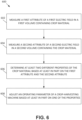
- FIG. 6 is a simplified flow chart illustrating a method 600 of measuring a harvested crop.
- a first attribute of a first electric field is measured in a first volume containing crop material.
- a second attribute of a second electric field is measured in a second volume (which may be the same or different than the first volume).
- the attributes measured may be resonant frequencies within the volumes.
- at least two different properties of the crop material are determined based at least in part on the first attribute and the second attribute.
- the properties determined may be permittivity, total moisture content, total mass, location (distance from any point on the sensor to the crop material, which can be used to determine crop orientation, crop distribution, velocity of crop material, etc .) , density, percentage moisture, mass flow, and/or total moisture flow.
- the properties may be determined as the crop material is harvested by an agricultural machine.
- an operating parameter of a crop-harvesting machine is adjusted based at least in part on one of the properties. For example, one or more of the properties may be reported to a controller that operates the agricultural machine, and used by the controller to change the operating parameter.
- Still other embodiments involve a computer-readable storage medium (e.g ., a non-transitory computer-readable storage medium) having processor-executable instructions configured to implement one or more of the techniques presented herein.
- a computer-readable storage medium e.g., a non-transitory computer-readable storage medium
- FIG. 7 An example computer-readable medium that may be devised is illustrated in FIG. 7 , wherein an implementation 700 includes a computer-readable storage medium 702 (e.g., a flash drive, CD-R, DVD-R, application-specific integrated circuit (ASIC), field-programmable gate array (FPGA), a platter of a hard disk drive, etc .), on which is computer-readable data 704.
- This computer-readable data 704 in turn includes a set of processor-executable instructions 706 configured to operate according to one or more of the principles set forth herein.
- the processor-executable instructions 706 may be configured to cause a computer associated with the windrower 510 ( FIG. 5 ) to perform operations 708 when executed via a processing unit, such as at least some of the example method 600 depicted in FIG. 6 .
- the processor-executable instructions 706 may be configured to implement a system, such as at least some of the example windrower 510 depicted in FIG. 5 .
- Many such computer-readable media may be devised by those of ordinary skill in the art that are configured to operate in accordance with one or more of the techniques presented herein.
Landscapes
- Life Sciences & Earth Sciences (AREA)
- Environmental Sciences (AREA)
- Chemical & Material Sciences (AREA)
- Health & Medical Sciences (AREA)
- Electrochemistry (AREA)
- Physics & Mathematics (AREA)
- Chemical Kinetics & Catalysis (AREA)
- Analytical Chemistry (AREA)
- Biochemistry (AREA)
- General Health & Medical Sciences (AREA)
- General Physics & Mathematics (AREA)
- Immunology (AREA)
- Pathology (AREA)
- Investigating Or Analyzing Materials By The Use Of Electric Means (AREA)
- Management, Administration, Business Operations System, And Electronic Commerce (AREA)
Claims (14)
- Verfahren zur Messung von Ernteguteigenschaften unter Nutzung eines Messgeräts innerhalb eines Rahmens oder getragen von einem Rahmen einer landwirtschaftlichen Maschine, wobei das Verfahren aufweist:Generieren, unter Nutzung des Messgeräts, eines ersten elektrischen Felds in einem ersten Volumen, das Erntegutmaterial aufweist;Messen eines ersten Attributs des ersten elektrischen Felds;Generieren, unter Nutzung des Messgeräts, eines zweiten elektrischen Felds in einem zweiten Volumen, das Erntegutmaterial aufweist, wobei das zweite elektrische Feld ein zu dem ersten elektrischen Feld unterschiedliches Volumen und/oder eine zu dem ersten elektrischen Feld unterschiedliche Antwortkurve aufweist;Messen eines zweiten Attributs des zweiten elektrischen Felds;Bestimmen mindestens zwei unterschiedlicher Erntegutmaterialeigenschaften zumindest teilweise basierend auf dem ersten Attribut und dem zweiten Attribut.
- Verfahren nach Anspruch 1, wobei das Bestimmen mindestens zwei unterschiedlicher Erntegutmaterialeigenschaften ein Messen mindestens zweier Eigenschaften aus Gesamtfeuchtigkeitsgehalt, Gesamtmasse, Ort, Dichte und/oder prozentualer Feuchtigkeit aufweist.
- Verfahren nach Anspruch 1, wobei das Bestimmen mindestens zwei unterschiedlicher Erntegutmaterialeigenschaften ein Messen eines Masseflusses und eines gesamten Feuchtigkeitsflusses aufweist.
- Verfahren nach Anspruch 1, wobei das Messen des ersten Attributs und das Messen des zweiten Attributs jeweils ein Messen einer wahrnehmbaren Ladung oder Last auf einem Sender aufweist, der das erste elektrische Feld und das zweite elektrische Feld generiert.
- Verfahren nach Anspruch 1, wobei das Messen des ersten Attributs und das Messen des zweiten Attributs jeweils ein Messen einer Permittivität des Erntegutmaterials aufweist.
- Verfahren nach Anspruch 1, wobei das Bestimmen mindestens zwei unterschiedlicher Erntegutmaterialeigenschaften ein Bestimmen mindestens zwei unterschiedlicher Eigenschaften, wenn das Erntegutmaterial durch die landwirtschaftliche Maschine geerntet wird, aufweist.
- Verfahren nach Anspruch 1, wobei die landwirtschaftliche Maschine eine Erntegut-Erntemaschine aufweist und wobei das Verfahren weiterhin ein Einstellen eines Betriebsparameters der Erntegut-Erntemaschine basierend zumindest teilweise auf einer der mindestens zwei unterschiedlichen Eigenschaften aufweist.
- Verfahren nach Anspruch 1, wobei die landwirtschaftliche Maschine eine Erntegut-Erntemaschine aufweist, und wobei das Verfahren weiterhin ein Übermitteln mindestens einer der mindestens zwei unterschiedlichen Eigenschaften an eine Steuerung aufweist, die ausgebildet ist, einen Betriebsparameter der Erntegut-Erntemaschine zu ändern.
- Verfahren nach Anspruch 1, wobei das Bestimmen mindestens zwei unterschiedlicher Erntegutmaterialeigenschaften ein Messen einer Resonanzfrequenz von Erntegutmaterial innerhalb des ersten elektrischen Felds und des zweiten elektrischen Felds aufweist.
- Verfahren nach Anspruch 9, wobei das Messen einer Resonanzfrequenz eines Senders, der das erste elektrische Feld und das zweite elektrische Feld generiert, ein Messen einer Änderung der Resonanzfrequenz des Erntegutmaterials aufweist.
- Verfahren nach Anspruch 1, wobei das zweite Volumen mit dem ersten Volumen übereinstimmt oder diese koextensiv sind.
- Verfahren nach Anspruch 1, wobei das zweite Volumen das erste Volumen teilweise überlappt.
- Verfahren nach Anspruch 1, wobei das zweite Volumen eine Summe des ersten Volumens und eines anderen Volumens aufweist.
- Nicht flüchtiges, computerlesbares Speichermedium, wobei das computerlesbare Speichermedium Instruktionen umfasst, die, wenn sie durch einen Computer ausgeführt werden, eine landwirtschaftliche Maschine mit einem Messgerät und dem Computer veranlassen, das Verfahren nach einem der Ansprüche 1 bis 13 auszuführen.
Applications Claiming Priority (2)
| Application Number | Priority Date | Filing Date | Title |
|---|---|---|---|
| US202063015219P | 2020-04-24 | 2020-04-24 | |
| PCT/IB2021/052488 WO2021214572A1 (en) | 2020-04-24 | 2021-03-25 | Methods of measuring harvested crop material |
Publications (2)
| Publication Number | Publication Date |
|---|---|
| EP4138539A1 EP4138539A1 (de) | 2023-03-01 |
| EP4138539B1 true EP4138539B1 (de) | 2024-10-09 |
Family
ID=75278312
Family Applications (1)
| Application Number | Title | Priority Date | Filing Date |
|---|---|---|---|
| EP21715335.2A Active EP4138539B1 (de) | 2020-04-24 | 2021-03-25 | Verfahren zur messung von ernteguteigenschaften |
Country Status (4)
| Country | Link |
|---|---|
| US (1) | US12372496B2 (de) |
| EP (1) | EP4138539B1 (de) |
| CA (1) | CA3175562A1 (de) |
| WO (1) | WO2021214572A1 (de) |
Families Citing this family (7)
| Publication number | Priority date | Publication date | Assignee | Title |
|---|---|---|---|---|
| EP4138539B1 (de) | 2020-04-24 | 2024-10-09 | Agco Corporation | Verfahren zur messung von ernteguteigenschaften |
| WO2021214579A1 (en) * | 2020-04-24 | 2021-10-28 | Agco Corporation | Agricultural machines comprising capacitive sensors, and related methods and apparatus |
| US11980131B2 (en) * | 2020-12-29 | 2024-05-14 | Agco Corporation | Skid plate for sensor integration |
| CA3214445A1 (en) | 2021-04-26 | 2022-11-03 | Agco Corporation | Methods and systems for labeling hay with corrected yield |
| WO2022229737A1 (en) | 2021-04-26 | 2022-11-03 | Agco Corporation | Methods and systems for labeling hay bales with corrected yield |
| GB2613713B (en) * | 2021-09-24 | 2023-11-08 | Univ Jiangsu | Threshing and cleaning device combining inertia and electrostatic field, and combine harvester |
| US20250072327A1 (en) * | 2023-08-30 | 2025-03-06 | Deere & Company | System and method for controlling windrower using crop constituents |
Family Cites Families (41)
| Publication number | Priority date | Publication date | Assignee | Title |
|---|---|---|---|---|
| US3430357A (en) | 1967-05-17 | 1969-03-04 | Weyerhaeuser Co | Method of drying wood and moisture indicator |
| US3739264A (en) * | 1971-06-11 | 1973-06-12 | Agridustrial Electronics | Grain moisture tester |
| GB2196129A (en) | 1986-10-10 | 1988-04-20 | Mineral Control Instr Pty | Capacitive moisture sensor |
| US5101163A (en) | 1989-10-04 | 1992-03-31 | Agar Corporation Ltd. | Oil/water measurement |
| DE4105857C2 (de) | 1991-02-25 | 1994-07-07 | Claas Ohg | Vorrichtung zur Messung eines Massestromes |
| DE59302704D1 (de) | 1992-08-22 | 1996-06-27 | Claas Ohg | Vorrichtung zur messung eines massestromes |
| DE4442711A1 (de) | 1994-12-01 | 1996-06-05 | Claas Ohg | Kapazitive Meßvorrichtung |
| US5572160A (en) | 1994-12-01 | 1996-11-05 | Teradyne, Inc. | Architecture for RF signal automatic test equipment |
| JP3528113B2 (ja) | 1995-11-20 | 2004-05-17 | ヤンマー農機株式会社 | 穀粒等の粒状被処理物流量の測定装置 |
| US5835054A (en) | 1996-03-01 | 1998-11-10 | The Regents Of The University Of California | Ultra wideband ground penetrating radar imaging of heterogeneous solids |
| DE19648126B4 (de) | 1996-11-21 | 2009-01-22 | Claas Kgaa Mbh | Selbstfahrender Feldhäcksler |
| US6242927B1 (en) * | 1997-04-09 | 2001-06-05 | Case Corporation | Method and apparatus measuring parameters of material |
| US6121782A (en) | 1997-04-09 | 2000-09-19 | Case Corporation | Method for measuring yield and moisture |
| US5930988A (en) | 1997-07-18 | 1999-08-03 | Hay & Forage Industries | On-the-go from the tractor seat windrow adjustment |
| US6215293B1 (en) | 1998-08-12 | 2001-04-10 | Solar Wide Industrial Limited | Portable stud detector for detecting wood, metal, and live wires |
| US6512475B1 (en) | 1999-04-02 | 2003-01-28 | Geophysical Survey Systems, Inc. | High-frequency dual-channel ground-penetrating impulse antenna and method of using same for identifying plastic pipes and rebar in concrete |
| US6421990B1 (en) * | 1999-05-19 | 2002-07-23 | Deere & Company | Measuring device for measuring components in and/or properties of crop material |
| US6487836B1 (en) * | 2001-03-20 | 2002-12-03 | Deere & Company | Crop moisture sensor for controlling harvesting speed |
| US6686749B2 (en) | 2001-10-25 | 2004-02-03 | Deere & Company | Multiple frequency grain moisture sensor for combines |
| US6784671B2 (en) | 2002-02-04 | 2004-08-31 | Mississippi State University | Moisture and density detector (MDD) |
| US20040077943A1 (en) | 2002-04-05 | 2004-04-22 | Meaney Paul M. | Systems and methods for 3-D data acquisition for microwave imaging |
| US20040190377A1 (en) | 2003-03-06 | 2004-09-30 | Lewandowski Robert Stephen | Method and means for isolating elements of a sensor array |
| US6806821B2 (en) | 2003-03-12 | 2004-10-19 | Itt Manufacturing Enterprises, Inc. | Apparatus and method for rapid detection of objects with time domain impulsive signals |
| US7119553B2 (en) | 2003-06-11 | 2006-10-10 | Konsulteurope Limited Limited Joint Stock Company | Security scanners with capacitance and magnetic sensor arrays |
| US7307575B2 (en) | 2004-09-14 | 2007-12-11 | Bae Systems Information And Electronic Systems Integration Inc. | Through-the-wall frequency stepped imaging system utilizing near field multiple antenna positions, clutter rejection and corrections for frequency dependent wall effects |
| US7298312B2 (en) | 2005-06-27 | 2007-11-20 | Itt Manufacturing Enterprises, Inc. | Detecting small, time domain impulsive communications signals |
| JP4834385B2 (ja) | 2005-11-22 | 2011-12-14 | 株式会社日立製作所 | プリント基板および電子装置 |
| US20130088245A1 (en) | 2011-10-10 | 2013-04-11 | Kla-Tencor Corporation | Capacitive Inspection Of EUV Photomasks |
| US9494538B2 (en) | 2014-04-04 | 2016-11-15 | Deere & Company | Agricultural moisture sensor with co-planar electrodes |
| US10290948B2 (en) | 2015-08-02 | 2019-05-14 | Vayyar Imaging Ltd | System and method for radio frequency penetration imaging of an object |
| US10371558B2 (en) | 2016-08-31 | 2019-08-06 | Deere & Company | System and method for measuring a bin level via an electromagnetic signal |
| US10448570B2 (en) | 2016-10-28 | 2019-10-22 | Deere & Company | System of laying swath of cut crop for improved dry down time and method thereof |
| US10408645B2 (en) | 2016-11-01 | 2019-09-10 | Deere & Company | Correcting bias in parameter monitoring |
| US10806078B2 (en) | 2017-05-12 | 2020-10-20 | Deere & Company | Control system for adjusting conditioning rollers of work vehicle |
| US10813287B2 (en) | 2017-05-12 | 2020-10-27 | Deere & Company | Control system for adjusting swath flap of windrowing work vehicle |
| US10912255B2 (en) | 2017-05-12 | 2021-02-09 | Deere & Company | Control system for adjusting forming shield of windrowing work vehicle |
| CA3009724C (en) | 2017-07-24 | 2021-03-23 | Agco Corporation | Automatic control of windrower swathboard |
| US20190110394A1 (en) | 2017-10-17 | 2019-04-18 | Kopper Kutter, LLC | Crop yield and obstruction detection system for a harvesting header |
| AU2019201061A1 (en) | 2018-02-16 | 2019-09-05 | ETEL Limited | A capacitive sensor |
| EP4138539B1 (de) | 2020-04-24 | 2024-10-09 | Agco Corporation | Verfahren zur messung von ernteguteigenschaften |
| CA3175437A1 (en) | 2020-04-24 | 2021-10-28 | Agco Corporation | Agricultural machines and methods for controlling windrow properties |
-
2021
- 2021-03-25 EP EP21715335.2A patent/EP4138539B1/de active Active
- 2021-03-25 WO PCT/IB2021/052488 patent/WO2021214572A1/en not_active Ceased
- 2021-03-25 US US17/906,769 patent/US12372496B2/en active Active
- 2021-03-25 CA CA3175562A patent/CA3175562A1/en active Pending
Also Published As
| Publication number | Publication date |
|---|---|
| US12372496B2 (en) | 2025-07-29 |
| WO2021214572A1 (en) | 2021-10-28 |
| US20230358707A1 (en) | 2023-11-09 |
| EP4138539A1 (de) | 2023-03-01 |
| CA3175562A1 (en) | 2021-10-28 |
Similar Documents
| Publication | Publication Date | Title |
|---|---|---|
| EP4138539B1 (de) | Verfahren zur messung von ernteguteigenschaften | |
| US20230345878A1 (en) | Agricultural machines and methods for controlling windrow properties | |
| US20230049727A1 (en) | Agricultural machines and methods for controlling windrow properties | |
| EP4023046A1 (de) | Mäher-aufbereiter-maschine zur erfassung des feuchtigkeitsgehalts von erntegut | |
| US10251340B2 (en) | Method for estimating feed quality of alfalfa as it is cut | |
| EP3932172A1 (de) | Verfahren zur messung von rückständen während der ernte | |
| US11930737B2 (en) | Self-propelled windrower with yield monitoring based on merger load | |
| EP4139669B1 (de) | Landwirtschaftliche maschinen mit kapazitiven sensoren und zugehörige verfahren und vorrichtungen | |
| US12543636B2 (en) | Methods and systems for labeling hay with corrected yield | |
| EP4338573A1 (de) | Landwirtschaftliches system zur erfassung von pflanzenmaterial | |
| EP4329472B1 (de) | Verfahren und systeme zur kennzeichnung von heuballen mit korrigiertem ertrag | |
| US20250143213A1 (en) | Geotagged windrow information | |
| US12543652B2 (en) | System and method for improving windrow dry-down | |
| US20250072327A1 (en) | System and method for controlling windrower using crop constituents | |
| US20260047523A1 (en) | Method to detect crop conditioning performance in roll type conditioners | |
| EP4292423A1 (de) | Konditionierungswalzen mit variabler geschwindigkeit für mäher- und konditionierer | |
| CA3244173A1 (en) | Windrow width and volumetric spread measurement of mower implement |
Legal Events
| Date | Code | Title | Description |
|---|---|---|---|
| STAA | Information on the status of an ep patent application or granted ep patent |
Free format text: STATUS: UNKNOWN |
|
| STAA | Information on the status of an ep patent application or granted ep patent |
Free format text: STATUS: THE INTERNATIONAL PUBLICATION HAS BEEN MADE |
|
| PUAI | Public reference made under article 153(3) epc to a published international application that has entered the european phase |
Free format text: ORIGINAL CODE: 0009012 |
|
| STAA | Information on the status of an ep patent application or granted ep patent |
Free format text: STATUS: REQUEST FOR EXAMINATION WAS MADE |
|
| 17P | Request for examination filed |
Effective date: 20221124 |
|
| AK | Designated contracting states |
Kind code of ref document: A1 Designated state(s): AL AT BE BG CH CY CZ DE DK EE ES FI FR GB GR HR HU IE IS IT LI LT LU LV MC MK MT NL NO PL PT RO RS SE SI SK SM TR |
|
| P01 | Opt-out of the competence of the unified patent court (upc) registered |
Effective date: 20230518 |
|
| DAV | Request for validation of the european patent (deleted) | ||
| DAX | Request for extension of the european patent (deleted) | ||
| REG | Reference to a national code |
Ref country code: DE Ref legal event code: R079 Free format text: PREVIOUS MAIN CLASS: A01D0041127000 Ipc: A01D0043080000 Ref country code: DE Ref legal event code: R079 Ref document number: 602021019939 Country of ref document: DE Free format text: PREVIOUS MAIN CLASS: A01D0041127000 Ipc: A01D0043080000 |
|
| GRAP | Despatch of communication of intention to grant a patent |
Free format text: ORIGINAL CODE: EPIDOSNIGR1 |
|
| STAA | Information on the status of an ep patent application or granted ep patent |
Free format text: STATUS: GRANT OF PATENT IS INTENDED |
|
| RIC1 | Information provided on ipc code assigned before grant |
Ipc: G01N 27/22 20060101ALI20240626BHEP Ipc: G01F 1/86 20060101ALI20240626BHEP Ipc: A01D 41/127 20060101ALI20240626BHEP Ipc: A01D 43/08 20060101AFI20240626BHEP |
|
| INTG | Intention to grant announced |
Effective date: 20240717 |
|
| GRAS | Grant fee paid |
Free format text: ORIGINAL CODE: EPIDOSNIGR3 |
|
| GRAA | (expected) grant |
Free format text: ORIGINAL CODE: 0009210 |
|
| STAA | Information on the status of an ep patent application or granted ep patent |
Free format text: STATUS: THE PATENT HAS BEEN GRANTED |
|
| AK | Designated contracting states |
Kind code of ref document: B1 Designated state(s): AL AT BE BG CH CY CZ DE DK EE ES FI FR GB GR HR HU IE IS IT LI LT LU LV MC MK MT NL NO PL PT RO RS SE SI SK SM TR |
|
| REG | Reference to a national code |
Ref country code: CH Ref legal event code: EP |
|
| REG | Reference to a national code |
Ref country code: DE Ref legal event code: R096 Ref document number: 602021019939 Country of ref document: DE |
|
| REG | Reference to a national code |
Ref country code: IE Ref legal event code: FG4D |
|
| REG | Reference to a national code |
Ref country code: LT Ref legal event code: MG9D |
|
| REG | Reference to a national code |
Ref country code: NL Ref legal event code: MP Effective date: 20241009 |
|
| REG | Reference to a national code |
Ref country code: AT Ref legal event code: MK05 Ref document number: 1729485 Country of ref document: AT Kind code of ref document: T Effective date: 20241009 |
|
| PG25 | Lapsed in a contracting state [announced via postgrant information from national office to epo] |
Ref country code: NL Free format text: LAPSE BECAUSE OF FAILURE TO SUBMIT A TRANSLATION OF THE DESCRIPTION OR TO PAY THE FEE WITHIN THE PRESCRIBED TIME-LIMIT Effective date: 20241009 |
|
| PG25 | Lapsed in a contracting state [announced via postgrant information from national office to epo] |
Ref country code: NL Free format text: LAPSE BECAUSE OF FAILURE TO SUBMIT A TRANSLATION OF THE DESCRIPTION OR TO PAY THE FEE WITHIN THE PRESCRIBED TIME-LIMIT Effective date: 20241009 |
|
| PG25 | Lapsed in a contracting state [announced via postgrant information from national office to epo] |
Ref country code: HR Free format text: LAPSE BECAUSE OF FAILURE TO SUBMIT A TRANSLATION OF THE DESCRIPTION OR TO PAY THE FEE WITHIN THE PRESCRIBED TIME-LIMIT Effective date: 20241009 Ref country code: PT Free format text: LAPSE BECAUSE OF FAILURE TO SUBMIT A TRANSLATION OF THE DESCRIPTION OR TO PAY THE FEE WITHIN THE PRESCRIBED TIME-LIMIT Effective date: 20250210 Ref country code: IS Free format text: LAPSE BECAUSE OF FAILURE TO SUBMIT A TRANSLATION OF THE DESCRIPTION OR TO PAY THE FEE WITHIN THE PRESCRIBED TIME-LIMIT Effective date: 20250209 |
|
| PGFP | Annual fee paid to national office [announced via postgrant information from national office to epo] |
Ref country code: DE Payment date: 20250319 Year of fee payment: 5 |
|
| PG25 | Lapsed in a contracting state [announced via postgrant information from national office to epo] |
Ref country code: FI Free format text: LAPSE BECAUSE OF FAILURE TO SUBMIT A TRANSLATION OF THE DESCRIPTION OR TO PAY THE FEE WITHIN THE PRESCRIBED TIME-LIMIT Effective date: 20241009 |
|
| PG25 | Lapsed in a contracting state [announced via postgrant information from national office to epo] |
Ref country code: BG Free format text: LAPSE BECAUSE OF FAILURE TO SUBMIT A TRANSLATION OF THE DESCRIPTION OR TO PAY THE FEE WITHIN THE PRESCRIBED TIME-LIMIT Effective date: 20241009 |
|
| PG25 | Lapsed in a contracting state [announced via postgrant information from national office to epo] |
Ref country code: ES Free format text: LAPSE BECAUSE OF FAILURE TO SUBMIT A TRANSLATION OF THE DESCRIPTION OR TO PAY THE FEE WITHIN THE PRESCRIBED TIME-LIMIT Effective date: 20241009 |
|
| PG25 | Lapsed in a contracting state [announced via postgrant information from national office to epo] |
Ref country code: NO Free format text: LAPSE BECAUSE OF FAILURE TO SUBMIT A TRANSLATION OF THE DESCRIPTION OR TO PAY THE FEE WITHIN THE PRESCRIBED TIME-LIMIT Effective date: 20250109 |
|
| PG25 | Lapsed in a contracting state [announced via postgrant information from national office to epo] |
Ref country code: LV Free format text: LAPSE BECAUSE OF FAILURE TO SUBMIT A TRANSLATION OF THE DESCRIPTION OR TO PAY THE FEE WITHIN THE PRESCRIBED TIME-LIMIT Effective date: 20241009 Ref country code: GR Free format text: LAPSE BECAUSE OF FAILURE TO SUBMIT A TRANSLATION OF THE DESCRIPTION OR TO PAY THE FEE WITHIN THE PRESCRIBED TIME-LIMIT Effective date: 20250110 Ref country code: AT Free format text: LAPSE BECAUSE OF FAILURE TO SUBMIT A TRANSLATION OF THE DESCRIPTION OR TO PAY THE FEE WITHIN THE PRESCRIBED TIME-LIMIT Effective date: 20241009 |
|
| PG25 | Lapsed in a contracting state [announced via postgrant information from national office to epo] |
Ref country code: PL Free format text: LAPSE BECAUSE OF FAILURE TO SUBMIT A TRANSLATION OF THE DESCRIPTION OR TO PAY THE FEE WITHIN THE PRESCRIBED TIME-LIMIT Effective date: 20241009 |
|
| PGFP | Annual fee paid to national office [announced via postgrant information from national office to epo] |
Ref country code: FR Payment date: 20250326 Year of fee payment: 5 |
|
| PGFP | Annual fee paid to national office [announced via postgrant information from national office to epo] |
Ref country code: IT Payment date: 20250319 Year of fee payment: 5 Ref country code: GB Payment date: 20250326 Year of fee payment: 5 |
|
| PG25 | Lapsed in a contracting state [announced via postgrant information from national office to epo] |
Ref country code: RS Free format text: LAPSE BECAUSE OF FAILURE TO SUBMIT A TRANSLATION OF THE DESCRIPTION OR TO PAY THE FEE WITHIN THE PRESCRIBED TIME-LIMIT Effective date: 20250109 |
|
| PG25 | Lapsed in a contracting state [announced via postgrant information from national office to epo] |
Ref country code: SM Free format text: LAPSE BECAUSE OF FAILURE TO SUBMIT A TRANSLATION OF THE DESCRIPTION OR TO PAY THE FEE WITHIN THE PRESCRIBED TIME-LIMIT Effective date: 20241009 |
|
| PG25 | Lapsed in a contracting state [announced via postgrant information from national office to epo] |
Ref country code: DK Free format text: LAPSE BECAUSE OF FAILURE TO SUBMIT A TRANSLATION OF THE DESCRIPTION OR TO PAY THE FEE WITHIN THE PRESCRIBED TIME-LIMIT Effective date: 20241009 |
|
| REG | Reference to a national code |
Ref country code: DE Ref legal event code: R097 Ref document number: 602021019939 Country of ref document: DE |
|
| PG25 | Lapsed in a contracting state [announced via postgrant information from national office to epo] |
Ref country code: EE Free format text: LAPSE BECAUSE OF FAILURE TO SUBMIT A TRANSLATION OF THE DESCRIPTION OR TO PAY THE FEE WITHIN THE PRESCRIBED TIME-LIMIT Effective date: 20241009 |
|
| PG25 | Lapsed in a contracting state [announced via postgrant information from national office to epo] |
Ref country code: RO Free format text: LAPSE BECAUSE OF FAILURE TO SUBMIT A TRANSLATION OF THE DESCRIPTION OR TO PAY THE FEE WITHIN THE PRESCRIBED TIME-LIMIT Effective date: 20241009 |
|
| PG25 | Lapsed in a contracting state [announced via postgrant information from national office to epo] |
Ref country code: SK Free format text: LAPSE BECAUSE OF FAILURE TO SUBMIT A TRANSLATION OF THE DESCRIPTION OR TO PAY THE FEE WITHIN THE PRESCRIBED TIME-LIMIT Effective date: 20241009 |
|
| PG25 | Lapsed in a contracting state [announced via postgrant information from national office to epo] |
Ref country code: CZ Free format text: LAPSE BECAUSE OF FAILURE TO SUBMIT A TRANSLATION OF THE DESCRIPTION OR TO PAY THE FEE WITHIN THE PRESCRIBED TIME-LIMIT Effective date: 20241009 |
|
| PLBE | No opposition filed within time limit |
Free format text: ORIGINAL CODE: 0009261 |
|
| STAA | Information on the status of an ep patent application or granted ep patent |
Free format text: STATUS: NO OPPOSITION FILED WITHIN TIME LIMIT |
|
| PG25 | Lapsed in a contracting state [announced via postgrant information from national office to epo] |
Ref country code: SE Free format text: LAPSE BECAUSE OF FAILURE TO SUBMIT A TRANSLATION OF THE DESCRIPTION OR TO PAY THE FEE WITHIN THE PRESCRIBED TIME-LIMIT Effective date: 20241009 |
|
| 26N | No opposition filed |
Effective date: 20250710 |
|
| PG25 | Lapsed in a contracting state [announced via postgrant information from national office to epo] |
Ref country code: MC Free format text: LAPSE BECAUSE OF FAILURE TO SUBMIT A TRANSLATION OF THE DESCRIPTION OR TO PAY THE FEE WITHIN THE PRESCRIBED TIME-LIMIT Effective date: 20241009 |
|
| REG | Reference to a national code |
Ref country code: CH Ref legal event code: H13 Free format text: ST27 STATUS EVENT CODE: U-0-0-H10-H13 (AS PROVIDED BY THE NATIONAL OFFICE) Effective date: 20251023 |
|
| PG25 | Lapsed in a contracting state [announced via postgrant information from national office to epo] |
Ref country code: LU Free format text: LAPSE BECAUSE OF NON-PAYMENT OF DUE FEES Effective date: 20250325 |
|
| REG | Reference to a national code |
Ref country code: BE Ref legal event code: MM Effective date: 20250331 |
|
| PG25 | Lapsed in a contracting state [announced via postgrant information from national office to epo] |
Ref country code: BE Free format text: LAPSE BECAUSE OF NON-PAYMENT OF DUE FEES Effective date: 20250331 |
|
| PG25 | Lapsed in a contracting state [announced via postgrant information from national office to epo] |
Ref country code: CH Free format text: LAPSE BECAUSE OF NON-PAYMENT OF DUE FEES Effective date: 20250331 |
|
| PG25 | Lapsed in a contracting state [announced via postgrant information from national office to epo] |
Ref country code: IE Free format text: LAPSE BECAUSE OF NON-PAYMENT OF DUE FEES Effective date: 20250325 |