EP4138412B1 - Verfahren zum entwurf einer line-array-lautsprecheranordnung - Google Patents
Verfahren zum entwurf einer line-array-lautsprecheranordnung Download PDFInfo
- Publication number
- EP4138412B1 EP4138412B1 EP21191526.9A EP21191526A EP4138412B1 EP 4138412 B1 EP4138412 B1 EP 4138412B1 EP 21191526 A EP21191526 A EP 21191526A EP 4138412 B1 EP4138412 B1 EP 4138412B1
- Authority
- EP
- European Patent Office
- Prior art keywords
- frequency responses
- array
- responses
- loudspeaker arrangement
- loudspeaker
- Prior art date
- Legal status (The legal status is an assumption and is not a legal conclusion. Google has not performed a legal analysis and makes no representation as to the accuracy of the status listed.)
- Active
Links
Images




Classifications
-
- H—ELECTRICITY
- H04—ELECTRIC COMMUNICATION TECHNIQUE
- H04R—LOUDSPEAKERS, MICROPHONES, GRAMOPHONE PICK-UPS OR LIKE ACOUSTIC ELECTROMECHANICAL TRANSDUCERS; ELECTRIC HEARING AIDS; PUBLIC ADDRESS SYSTEMS
- H04R1/00—Details of transducers, loudspeakers or microphones
- H04R1/20—Arrangements for obtaining desired frequency or directional characteristics
-
- H—ELECTRICITY
- H04—ELECTRIC COMMUNICATION TECHNIQUE
- H04R—LOUDSPEAKERS, MICROPHONES, GRAMOPHONE PICK-UPS OR LIKE ACOUSTIC ELECTROMECHANICAL TRANSDUCERS; ELECTRIC HEARING AIDS; PUBLIC ADDRESS SYSTEMS
- H04R1/00—Details of transducers, loudspeakers or microphones
- H04R1/20—Arrangements for obtaining desired frequency or directional characteristics
- H04R1/32—Arrangements for obtaining desired frequency or directional characteristics for obtaining desired directional characteristic only
- H04R1/40—Arrangements for obtaining desired frequency or directional characteristics for obtaining desired directional characteristic only by combining a number of identical transducers
- H04R1/403—Arrangements for obtaining desired frequency or directional characteristics for obtaining desired directional characteristic only by combining a number of identical transducers loud-speakers
-
- H—ELECTRICITY
- H04—ELECTRIC COMMUNICATION TECHNIQUE
- H04R—LOUDSPEAKERS, MICROPHONES, GRAMOPHONE PICK-UPS OR LIKE ACOUSTIC ELECTROMECHANICAL TRANSDUCERS; ELECTRIC HEARING AIDS; PUBLIC ADDRESS SYSTEMS
- H04R29/00—Monitoring arrangements; Testing arrangements
- H04R29/001—Monitoring arrangements; Testing arrangements for loudspeakers
- H04R29/002—Loudspeaker arrays
-
- H—ELECTRICITY
- H04—ELECTRIC COMMUNICATION TECHNIQUE
- H04R—LOUDSPEAKERS, MICROPHONES, GRAMOPHONE PICK-UPS OR LIKE ACOUSTIC ELECTROMECHANICAL TRANSDUCERS; ELECTRIC HEARING AIDS; PUBLIC ADDRESS SYSTEMS
- H04R3/00—Circuits for transducers
- H04R3/04—Circuits for transducers for correcting frequency response
-
- H—ELECTRICITY
- H04—ELECTRIC COMMUNICATION TECHNIQUE
- H04R—LOUDSPEAKERS, MICROPHONES, GRAMOPHONE PICK-UPS OR LIKE ACOUSTIC ELECTROMECHANICAL TRANSDUCERS; ELECTRIC HEARING AIDS; PUBLIC ADDRESS SYSTEMS
- H04R3/00—Circuits for transducers
- H04R3/12—Circuits for transducers for distributing signals to two or more loudspeakers
- H04R3/14—Cross-over networks
-
- H—ELECTRICITY
- H04—ELECTRIC COMMUNICATION TECHNIQUE
- H04S—STEREOPHONIC SYSTEMS
- H04S7/00—Indicating arrangements; Control arrangements, e.g. balance control
- H04S7/30—Control circuits for electronic adaptation of the sound field
- H04S7/307—Frequency adjustment, e.g. tone control
-
- H—ELECTRICITY
- H04—ELECTRIC COMMUNICATION TECHNIQUE
- H04R—LOUDSPEAKERS, MICROPHONES, GRAMOPHONE PICK-UPS OR LIKE ACOUSTIC ELECTROMECHANICAL TRANSDUCERS; ELECTRIC HEARING AIDS; PUBLIC ADDRESS SYSTEMS
- H04R2201/00—Details of transducers, loudspeakers or microphones covered by H04R1/00 but not provided for in any of its subgroups
- H04R2201/40—Details of arrangements for obtaining desired directional characteristic by combining a number of identical transducers covered by H04R1/40 but not provided for in any of its subgroups
- H04R2201/403—Linear arrays of transducers
-
- H—ELECTRICITY
- H04—ELECTRIC COMMUNICATION TECHNIQUE
- H04R—LOUDSPEAKERS, MICROPHONES, GRAMOPHONE PICK-UPS OR LIKE ACOUSTIC ELECTROMECHANICAL TRANSDUCERS; ELECTRIC HEARING AIDS; PUBLIC ADDRESS SYSTEMS
- H04R2203/00—Details of circuits for transducers, loudspeakers or microphones covered by H04R3/00 but not provided for in any of its subgroups
- H04R2203/12—Beamforming aspects for stereophonic sound reproduction with loudspeaker arrays
-
- H—ELECTRICITY
- H04—ELECTRIC COMMUNICATION TECHNIQUE
- H04S—STEREOPHONIC SYSTEMS
- H04S7/00—Indicating arrangements; Control arrangements, e.g. balance control
- H04S7/30—Control circuits for electronic adaptation of the sound field
- H04S7/301—Automatic calibration of stereophonic sound system, e.g. with test microphone
Definitions
- the disclosure relates to a method for designing a line array loudspeaker arrangement.
- WO 2018/045133 Al discloses a more analytic method, in which a first array of M speaker elements is disposed in a cylindrical configuration about an axis and configured to play back audio at a first range of frequencies. A second array of N speaker elements is disposed in a cylindrical configuration about the axis and configured to play back audio at a second range of frequencies.
- a digital signal processor generates a first plurality of output channels from an input channel for the first range of frequencies, apply the first plurality of output channels to the first array of speaker elements using a first rotation matrix to generate a first beam of audio content at a target angle about the axis, generate a second plurality of output channels from the input channel for the second range of frequencies, and apply the second plurality of output channels to the second array of speaker elements using a second rotation matrix to generate a second beam of audio content at the target angle.
- An analytic design method for loudspeaker arrangements is desired that allows to produce desired frequency responses directly at any given point in space.
- a method for designing a line array loudspeaker arrangement in which the loudspeaker arrangement comprises electronic filters and a loudspeaker enclosure equipped with loudspeakers.
- the loudspeakers are connected downstream of the filters, have a membrane, and are arranged to form at least two arrays.
- the method comprises providing design start parameters including a number of loudspeaker arrays, a number of loudspeakers per array, distances between loudspeakers per array and loudspeaker membrane sizes per array; providing a loudspeaker arrangement based on the design start parameters and including the at least two arrays, wherein one of the at least two arrays is a first vertical array and the loudspeakers of the first vertical array are multiway loudspeakers; and measuring the frequency responses of the loudspeaker arrangement with bypassed or omitted electronic filters at predefined horizontal angle increments.
- the method further comprises computing combined beam forming and crossover filter frequency responses for the first vertical array based on the measured frequency responses of the loudspeaker arrangement and first target frequency responses at various frequency points and various positions, the first target frequency responses being constant-beam-width transducer target frequency responses that specify desired frequency responses of the line array loudspeaker arrangement to be designed.
- the method further comprises computing combined equalizing and crossover filter frequency responses for the first vertical array based on second target frequency responses, the second target frequency responses being the combined beam forming and crossover filter frequency responses for the first vertical array, and the combined equalizing and crossover filter frequency responses being configured to obtain acoustic linear phase responses of the line array loudspeaker arrangement.
- the method further comprises computing horizontal beam forming filter frequency responses based on the measured frequency responses of the loudspeaker arrangement and third target frequency responses, the third target frequency responses specifying desired horizontal frequency responses of the line array loudspeaker arrangement to be designed; and designing the electronic filters based on the combined beam forming and crossover filter frequency responses for the first vertical array, the equalizing and crossover filter frequency responses, and the horizontal beam forming filter frequency responses, wherein computing first vertical beam forming crossover filter parameters for the first vertical array comprises a nonlinear optimization procedure minimizing at each frequency point a first error that corresponds with the difference between the measured frequency response of the loudspeaker arrangement and the constant-beam-width transducer directivity target frequency responses.
- a vertical beamforming crossover design is employed. It is desirable to combine a traditional loudspeaker array design having specialized (multiway) loudspeakers such as, for example, tweeters, midranges and woofers, with an array control technique such as, for example, a beamforming technique, so that not only the directivity and smoothness of out-of-axis responses, but also other requirements such as low distortion across the frequency band, efficiency and maximum sound power level at a given enclosure size can be satisfied.
- a linear-phase design technique for multiway loudspeakers as disclosed, for example, in United States Patent US7991170 requires very tight spacing in the center, does not allow the use of large, powerful transducers, and demands low crossover frequencies, which may result in impaired power handling and low achievable loudness level.
- the designs provided by these methods are optimized for a prescribed listening distance D and a vertically and horizontally extending (only the vertical dimension is shown in Figure 1 ) listening window having at the listening point a height (zero to H) measured from a center axis 101 of an exemplary loudspeaker arrangement 102, as depicted in Figure 1 .
- the design methods presented herein are based on the following considerations:
- GLA Generalized Line Array
- multiway loudspeakers 103 i.e., specialized loudspeakers such as tweeters, midranges and woofers, are arranged in a cabinet 104 and array-wise in line with each other to form a front array, wherein the highest frequency loudspeakers are disposed close to or in the center, and the lowest frequency loudspeakers are close to the vertically opposing edges of the loudspeaker arrangement 102.
- loudspeakers 103 i.e., specialized loudspeakers such as tweeters, midranges and woofers
- the highest frequency loudspeakers are disposed close to or in the center
- the lowest frequency loudspeakers are close to the vertically opposing edges of the loudspeaker arrangement 102.
- not only one but also multiple (i.e., at least two) loudspeakers are allowed at each position, wherein the membrane diameters of the loudspeakers at each position are summed up.
- the two loudspeakers at each of vertical positions x 2 , ... x Dm are horizontally shifted by ⁇ 45° related to the position of the loudspeakers at vertical positions 0 and x 1 .
- concave (arc-shaped) distribution of the loudspeakers 103 around a horizontal axis of the cabinet 104 there may be, for example, a vertical arrangement of two transducers at position 0 and horizontal arrangements of two transducers at vertical positions x 2 , ... x Dm .
- Constant-beamwidth transducers are curved-surface transducers in the form of a spherical cap with frequency-independent Legendre shading, or as herein, Squared Cosine Shading that provides wide-band constant beamwidth and directivity behavior with virtually no side lobes.
- CBT arrays employ amplitude shading (gain factors) and geometrically realized delays (by means of an arc-shaped enclosure) to achieve a desired beam shape as detailed, for example, in R. Taylor, K. Manke, D.B. Keele, "Circular-Arc Line Arrays with Amplitude Shading for Constant Directivity". J. Audio Eng. Soc., Vol. 67, No. 6, June 2019 .
- Logarithmic arrays are based on a bank of low pass filters as detailed, for example, in M. Van der Wal, E. Start, D. De Vries, "Design of logarithmically spaced constant-directivity transducer arrays", J.A.E.S. Vol. 44 No. 6, June 1996 .
- Conventional loudspeaker crossover arrangements employ band pass filter designs having high passes and low passes.
- w Dm [ f Dm ,...f 1 , f 0 , f 1 ,...f Dm ]
- g d [ g Dm ,...g 1 ,0, g 1 ,... g Dm ] .
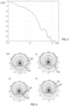
- Figure 3 depicts examples of the resulting low pass frequency responses as levels A [dB] vs. frequency f [Hz] of various low pass filters.
- CBT arc arrays are described, e.g., in R. Taylor, K. Manke, D.B. Keele, "Circular-Arc Line Arrays with Amplitude Shading for Constant Directivity”. J. Audio Eng. Soc., Vol. 67, No. 6, June 2019 .
- the CBT target frequency response H T is derived by computing target responses as a sum of M c discrete point sources (e.g., loudspeakers) on the surface of the arc according to:
- a horizontal crossover design is obtained that includes multiple vertical arrays, pointing to different angular room directions.
- a vertical array is an array of loudspeakers that are vertically aligned.
- Higher order directivity characteristics can be achieved by adding multiple side arrays.
- Real-valued target frequency responses T(q,i) specify the desired horizontal system responses, for example, the above-mentioned first order cardioid function.
- the parameter a represents a level that specifies how much louder the combined system plays compared to one single driver array.
- Variables for the nonlinear optimization are magnitude
- and phase arg( C r ( i )) arctan ( Im ⁇ C r ( i ) ⁇ / Re ⁇ C r ( i ) ⁇ ) of the unknown beam forming filters.
- G max 20 ⁇ log(max(
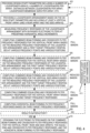
- FIG. 4 A flow chart illustrating an example design method according to the disclosure presented above is shown in Figure 4 . After going through a number of steps outlined below, a new iteration may be conducted if the result is not satisfactory. Transducer distances, and, as the case may be, the number of transducers and membrane sizes may be adapted before a new iteration round. The sequence of steps in the chart is exemplary and may vary as the case may be.
- design start parameters are provided including a number of (vertical) loudspeaker arrays, a number of loudspeakers per array, distances between loudspeakers per array and loudspeaker membrane sizes per array.
- a number of (vertical) loudspeaker arrays For example, an (initial) best guess of the loudspeaker arrangement is made by a designer. The (initial) best guess may be at least the number of vertical arrays, the number of loudspeakers per array, distances between loudspeakers in each array and membrane sizes in each array.
- Optional further parameters that may be included in the (initial) best guess may include at least one of orientation of the arrays, enclosure shape, and type of loudspeakers (specified by, e.g., at least one of frequency range, power, impedance).
- the initial best guess or subsequent best guesses may be adapted manually by a designer or automatically by, e.g., software, when an/another iteration round is initiated.
- a loudspeaker arrangement is provided which is based on the design start parameters and which includes at least a vertical front array.
- a prototype enclosure equipped with loudspeakers is provided based on the (initial) best guess of the loudspeaker arrangement according to the first step 401 or to the outcome of a previous iteration round.
- acoustic frequency responses of the loudspeaker arrangement are measured with any electronic filters, e.g., beamforming and crossover filters, connected upstream of the loudspeakers bypassed or omitted, and at predefined horizontal angle increments.
- electronic filters e.g., beamforming and crossover filters
- a fourth step 404 combined beam forming and crossover filter frequency responses for the vertical front array are computed based on the measured frequency responses of the loudspeaker arrangement and first target frequency responses at various frequency points and various positions.
- the first target frequency responses are constant-beam-width transducer target frequency responses that specify desired frequency responses of the loudspeaker array to be designed.
- the frequency responses of front vertical beam forming crossover filters which are filters that combine a beam forming filter and a crossover filter, e.g., in a single filter as shown in Figure 11 , and which are represented by the filter parameters dd, wd, fd, gd, are computed for an, e.g., full bandwidth front array based on CBT directivity target frequency responses such as, for example, in the way outlined above in connection with and based on the CBT directivity target frequency responses H T ( l, f ) and the measured acoustic frequency responses H w ( l, f) of the loudspeaker arrangement resulting from the third step 403.
- CBT directivity target frequency responses such as, for example, in the way outlined above in connection with and based on the CBT directivity target frequency responses H T ( l, f ) and the measured acoustic frequency responses H w ( l, f) of the loudspeaker arrangement resulting from the third step 403.
- step 405 combined beam forming and crossover filter frequency responses for an optional vertical rear array are computed based on the measured frequency responses of the loudspeaker arrangement and the first target frequency responses at various frequency points and various positions in a manner similar to the one outlined above in connection with the fourth step 404.
- step 406 combined beam forming and crossover filter frequency responses for optional vertical side arrays are computed based on the measured frequency responses of the loudspeaker arrangement and the first target frequency responses at various frequency points and various positions in a manner similar to the one outlined above in connection with the fourth step 404.
- frequency responses of rear vertical beam forming crossover filters are computed for a rear array based on the CBT directivity target frequency responses H T ( l, f) and the resulting acoustic frequency responses H w ( l, f) of the rear array.
- side beam-forming crossover filters may be designed in a similar manner for at least one optional side array based on the CBT directivity target function H T ( l, f ) and the measured acoustic frequency responses H w ( l , f ) of the loudspeaker arrangement.
- Designing the filters for the rear array and the optional side array(s) includes computing frequency responses of the beam forming crossover filters to be designed, for example, in the way outlined above in connection with and based on the CBT directivity target frequency responses H T ( l, f ) and the measured acoustic frequency responses H w ( l, f) of the loudspeaker arrangement. It is noted that the bandwidth of the rear array or of the one or two optional side arrays or of rear and side array(s) may be reduced because sound diffracted around an enclosure experiences a natural attenuation at high frequencies in the form of shadowing. A level vs.
- a seventh step 407 combined equalizing and crossover filter frequency responses for the vertical front array are computed based on second target frequency responses, the second target frequency responses being the combined beam forming and crossover filter frequency responses for the vertical front array, and the combined equalizing and crossover filter frequency responses being configured to obtain acoustic linear phase responses of the loudspeaker arrangement.
- the beam forming crossover filters from the fourth step 404 (and fifth step 405 and/or sixth step 406), which may be zero-phase except for the delay vector, are taken as target frequency responses to compute the frequency responses of combined equalizing and crossover filters, for example the filters 707 and 711 in the signal processing structure shown in Figure 7 .
- H CR H C H M
- H C the target filter frequency responses as a result of the optimization, as outlined above with MatLab function "fmincon”
- H M represents the measured responses.
- computing horizontal beam forming filter frequency responses is based on third target frequency responses (e.g., target frequency responses T(q,i) above).
- the third target frequency responses specify desired horizontal frequency responses of the loudspeaker array to be designed.
- the horizontal beamforming filters C r are implemented as FIR filters in full bandwidth.
- step 409 it is checked whether the achieved results are satisfactory. This may be performed by measuring the acoustic frequency responses of the loudspeaker arrangement involving all filters.
- the electronic filters are designed based on (e.g., computed from) the combined beam forming and crossover filter frequency responses for the vertical front array, the equalizing and crossover filter frequency responses, and the horizontal beam forming filter frequency responses.
- step 411 at least one of the design start parameters is changed and the steps 401-409 are repeated.
- a block diagram of a signal processing structure implemented in a digital signal processor (DSP) and configured to drive the loudspeakers of at least two loudspeaker arrays is shown in Figure 7 .
- a time-discrete input signal x is supplied to a front array signal path 701, a rear array signal path 702 and an optional side array path 703 (not shown in detail).
- the front array signal path 701 includes a delay element 704 for delay time compensation, a subsequent frequency equalizer 705 (e.g., implemented by way of a multiplicity of biquad filters) for frequency compensation, and a subsequent vertical beamforming / crossover network 706 (e.g., implemented as a bank of finite impulse response (FIR) filters 707).
- FIR finite impulse response
- the rear array signal path 702 includes a FIR filter 708 for horizontal beamforming, a subsequent frequency equalizer 709 (e.g., implemented with a multiplicity of biquad filters) for frequency compensation, and a subsequent crossover network 710 (e.g., implemented as a bank of finite impulse response (FIR) filters 711).
- the outputs of filters 707 drive the center loudspeaker or the center pair of loudspeakers and the remaining pairs of loudspeakers of the front array.
- the outputs of filters 711 drive the center loudspeaker or the center pair of loudspeakers and the remaining pairs of loudspeakers of the rear array.
- Crossover filters and horizontal beam forming filters may be finite impulse response (FIR) filters of length 128 ... 512.
- Figure 8 shows three views A (front view), B (side view) and C (rear view) of a slim tower GLA loudspeaker arrangement 801, including three vertical arrays 802, 803 and 804.
- the two frontal arrays 802 and 803 share a mutual tweeter section 805, and may be electrically connected in parallel.
- Two tweeters 806 are disposed in the center of the tweeter section 805 and, thus, the loudspeaker arrangement 801, and electrically connected in parallel.
- the distance between the two tweeters 806 is chosen such that the resulting vertical directivity matches the directivity of the whole arrays 802 and 803. Overall height may be, for example, about 1.5 meter (m).
- Figure 9 shows frequency response plots 901 (level A [dB] vs.
- the combined front arrays 802 and 803 are controlled by six loudspeaker channels, the rear array 804 by five.
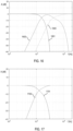
- Figures 11 and 12 show the crossover transfer functions 1101-1106 (front) and 1201-1205 (rear) for the particular channels as level A [dB] vs. frequency f [Hz].
- Parameters for the design shown in Figure 8 are for the front array:
- FIG. 13 An example configuration with the minimum number of loudspeaker channels possible, but which is still in accordance with this disclosure, is shown in Figure 13 . It includes a compact, bookshelf type loudspeaker arrangement 1301 with a three-channel front array 1301 (view A) and a two-channel rear array 1302 (view B).
- the front array 1301 includes three tweeters 1303 in the center of the front array 1301 and two woofers 1304 distant from this center.
- the rear array 1302 includes a midrange 1306 in the center of the rear array 1302 and two woofers 1304 distant from this center.
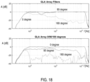
- Figure 18 depicts frequency responses (level A [dB] vs. frequency f [Hz]) horizontally at 0°, 90° and 180° (see lower diagram) of a loudspeaker front array 1301, the horizontal beam filter responses of which are shown in the upper diagram, as a result of an iteration process as described above in connection with the horizontal beamforming crossover design. As predicted, there is more than 20dB attenuation of the rear filter response above 3 KHz.
- the design parameters are for the front array 1301:
- the method may be implemented partly by software and/or firmware stored on or in a computer-readable medium, machine-readable medium, propagated-signal medium, and/or signal-bearing medium.
- the media may comprise any device that contains, stores, communicates, propagates, or transports executable instructions for use by or in connection with an instruction executable system, apparatus, or device.
- the machine-readable medium may selectively be, but is not limited to, an electronic, magnetic, optical, electromagnetic, or infrared signal or a semiconductor system, apparatus, device, or propagation medium.
- the systems may include additional or different logic and may be implemented in many different ways, e.g., as a microprocessor, microcontroller, application specific integrated circuit (ASIC), discrete logic, or a combination of other types of circuits or logic.
- memories may be DRAM, SRAM, Flash, or other types of memory.
- Parameters (e.g., conditions and thresholds) and other data structures may be separately stored and managed, may be incorporated into a single memory or database, or may be logically and physically organized in many different ways.
- Programs and instruction sets may be parts of a single program, separate programs, or distributed across several memories and processors.
Landscapes
- Physics & Mathematics (AREA)
- Engineering & Computer Science (AREA)
- Acoustics & Sound (AREA)
- Signal Processing (AREA)
- Health & Medical Sciences (AREA)
- Otolaryngology (AREA)
- General Health & Medical Sciences (AREA)
- Circuit For Audible Band Transducer (AREA)
- Obtaining Desirable Characteristics In Audible-Bandwidth Transducers (AREA)
Claims (14)
- Verfahren zum Entwerfen einer Line-Array-Lautsprecheranordnung (102), wobei die Lautsprecheranordnung elektronische Filter und ein Lautsprechergehäuse umfasst, das mit Lautsprechern ausgestattet ist, die den Filtern nachgeschaltet sind, eine Membran aufweisen und angeordnet sind, um mindestens zwei Arrays zu bilden; wobei das Verfahren Folgendes umfasst:Bereitstellen (401) von Entwurfsstartparametern, die eine Anzahl von Lautsprecherarrays, eine Anzahl von Lautsprechern pro Array, Abstände zwischen Lautsprechern pro Array und Lautsprechermembrangrößen pro Array beinhalten;Bereitstellen (402) einer Lautsprecheranordnung basierend auf den Entwurfsstartparametern und beinhaltend die mindestens zwei Arrays, wobei eines der mindestens zwei Arrays ein erstes vertikales Array ist und die Lautsprecher des ersten vertikalen Arrays Mehrwegelautsprecher sind;Messen (403) der Frequenzantworten der Lautsprecheranordnung mit umgangenen oder ausgelassenen elektronischen Filtern in vordefinierten horizontalen Winkelinkrementen;Berechnen (404) von kombinierten Strahlformungs- und Crossover-Filter-Frequenzantworten für ein erstes vertikales Array basierend auf den gemessenen Frequenzantworten der Lautsprecheranordnung und ersten Ziel-Frequenzantworten an verschiedenen Frequenzpunkten und verschiedenen Positionen, wobei die ersten Ziel-Frequenzantworten Ziel-Frequenzantworten eines Wandlers mit konstanter Strahlbreite sind, die gewünschte Frequenzantworten der zu entwerfenden Line-Array-Lautsprecheranordnung festlegen;Berechnen (407) von kombinierten Entzerrungs- und Crossover-Filter-Frequenzantworten für das erste vertikale Array basierend auf zweiten Ziel-Frequenzantworten, wobei die zweiten Ziel-Frequenzantworten die kombinierten Strahlformungs- und Crossover-Filter-Frequenzantworten für das erste vertikale Array sind und die kombinierten Entzerrungs- und Crossover-Filter-Frequenzantworten dazu konfiguriert sind, akustische lineare Phasenantworten der Line-Array-Lautsprecheranordnung zu erlangen;Berechnen (408) von horizontalen Strahlformungs-Filterfrequenzantworten basierend auf den gemessenen Frequenzantworten der Lautsprecheranordnung und dritten Ziel-Frequenzantworten, wobei die dritten Ziel-Frequenzantworten gewünschte horizontale Frequenzantworten der zu entwerfenden Line-Array-Lautsprecheranordnung festlegen; undEntwerfen (410) der elektronischen Filter basierend auf den kombinierten Strahlformungs- und Crossover-Filter-Frequenzantworten für das erste vertikale Array, den Entzerrungs- und Crossover-Filter-Frequenzantworten und den horizontalen Strahlformungs-Filterfrequenzantworten, wobei ein Berechnen von vertikalen Strahlformungs-Crossover-Filterparametern für das erste vertikale Array eine nichtlineare Optimierungsprozedur umfasst, die an jedem Frequenzpunkt einen ersten Fehler minimiert, der der Differenz zwischen der gemessenen Frequenzantwort der Lautsprecheranordnung und den Ziel-Frequenzantworten einer Richtwirkung des Wandlers mit konstanter Strahlbreite entspricht.
- Verfahren nach Anspruch 1, wobei die Line-Array-Lautsprecheranordnung ferner ein zweites vertikales Array umfasst, wobei das zweite vertikale Array auf einer gegenüberliegenden Seite des ersten vertikalen Arrays angeordnet ist und wobei das Verfahren ferner Berechnen von Strahlformungs- und Crossover-Filterantworten für das zweite vertikale Array basierend auf den gemessenen Frequenzantworten der Lautsprecheranordnung und den ersten Ziel-Frequenzantworten an verschiedenen Frequenzpunkten und verschiedenen Positionen umfasst.
- Verfahren nach Anspruch 1 oder 2, wobei die Line-Array-Lautsprecheranordnung ferner ein drittes vertikales Array umfasst, wobei das dritte vertikale Array seitlich von mindestens einem von dem ersten und dem zweiten vertikalen Array angeordnet ist und wobei das Verfahren ferner Berechnen von Strahlformungs- und Crossover-Filterantworten für das dritte vertikale Array basierend auf den gemessenen Frequenzantworten der Lautsprecheranordnung und den ersten Ziel-Frequenzantworten an verschiedenen Frequenzpunkten und verschiedenen Positionen umfasst.
- Verfahren nach einem der Ansprüche 1-3, ferner umfassend Ändern mindestens eines der Entwurfsstartparameter und Wiederholen von mindestens: Bereitstellen der Lautsprecheranordnung, Messen der Frequenzantworten der Lautsprecheranordnung, Berechnen der kombinierten Strahlformungs- und Crossover-Filterantworten für das erste vertikale Array, Berechnen der kombinierten Entzerrungs- und Crossover-Filter-Frequenzantworten für das erste vertikale Array und Berechnen der horizontalen Strahlformungs-Filterfrequenzantworten.
- Verfahren nach einem der Ansprüche 1-4, wobei die Entwurfsstartparameter ferner mindestens eines von Anzahl der vertikalen Arrays, Ausrichtung der Arrays, Form des Gehäuses und Typ des Lautsprechers beinhalten.
- Verfahren nach einem der Ansprüche 1-5, wobei das Berechnen der kombinierten Strahlformungs- und Crossover-Filter-Frequenzantworten für das erste vertikale Array über die volle Betriebsbandbreite des Lautsprecherarrays durchgeführt wird.
- Verfahren nach einem der Ansprüche 2-6, wobei mindestens eines von Folgenden mit einer Bandbreite durchgeführt wird, die kleiner als die volle Betriebsbandbreite des Lautsprecherarrays ist: Berechnen der Strahlformungs- und Crossover-Filterantworten für das zweite vertikale Array und Berechnen der Strahlformungs- und Crossover-Filterantworten für das dritte vertikale Array.
- Verfahren nach einem der Ansprüche 1-7, wobei das Richtwirkungsziel des Wandlers mit konstanter Strahlbreite durch Berechnen einer Summe einer Anzahl einzelner Punktquellen auf einer Fläche eines Lichtbogens abgeleitet wird.
- Verfahren nach Anspruch 8, wobei das Richtwirkungsziel des Wandlers mit konstanter Strahlbreite von einer Shading-Funktion abhängig ist.
- Verfahren nach einem der Ansprüche 2-9, wobei ein Berechnen von zweiten vertikalen Strahlformungs-Crossover-Filterparametern für das zweite vertikale Array eine Optimierungsprozedur umfasst, die an jedem Frequenzpunkt einen ersten Fehler minimiert, der der Differenz zwischen der gemessenen Frequenzantwort der Lautsprecheranordnung und den Ziel-Frequenzantworten der Richtwirkung des Wandlers mit konstanter Strahlbreite entspricht.
- Verfahren nach Anspruch 10, wobei die Optimierungsprozedur nichtlinear ist.
- Verfahren nach einem der Ansprüche 1-11, wobei es sich bei den akustischen Frequenzantworten der Lautsprecheranordnung um die komplexe Summe der Frequenzantworten aller Lautsprecher bei unterschiedlichen Winkeln handelt.
- Verfahren nach einem der Ansprüche 1-12, wobei das Berechnen der horizontalen Strahlformungs-Filterfrequenzantworten eine nichtlineare Optimierung umfasst, indem an jedem Frequenzpunkt ein zweiter Fehler minimiert wird, der der Differenz zwischen der gemessenen Frequenzantwort der Lautsprecheranordnung und den dritten Ziel-Frequenzantworten bei vordefinierten horizontalen Winkelinkrementen entspricht.
- Verfahren nach einem der Ansprüche 1-13, wobei die verschiedenen Positionen, an denen die kombinierten Strahlformungs- und Crossover-Filter-Frequenzantworten für das erste vertikale Array innerhalb eines vertikal und horizontal verlaufenden Hörfensters in einem Hörabstand von einem Zentrum der Lautsprecheranordnung berechnet werden.
Priority Applications (3)
| Application Number | Priority Date | Filing Date | Title |
|---|---|---|---|
| EP21191526.9A EP4138412B1 (de) | 2021-08-16 | 2021-08-16 | Verfahren zum entwurf einer line-array-lautsprecheranordnung |
| CN202210840752.3A CN115706888A (zh) | 2021-08-16 | 2022-07-18 | 用于设计线阵列扬声器布置的方法 |
| US17/881,002 US12089017B2 (en) | 2021-08-16 | 2022-08-04 | Method for designing a line array loudspeaker arrangement |
Applications Claiming Priority (1)
| Application Number | Priority Date | Filing Date | Title |
|---|---|---|---|
| EP21191526.9A EP4138412B1 (de) | 2021-08-16 | 2021-08-16 | Verfahren zum entwurf einer line-array-lautsprecheranordnung |
Publications (2)
| Publication Number | Publication Date |
|---|---|
| EP4138412A1 EP4138412A1 (de) | 2023-02-22 |
| EP4138412B1 true EP4138412B1 (de) | 2025-05-14 |
Family
ID=77367256
Family Applications (1)
| Application Number | Title | Priority Date | Filing Date |
|---|---|---|---|
| EP21191526.9A Active EP4138412B1 (de) | 2021-08-16 | 2021-08-16 | Verfahren zum entwurf einer line-array-lautsprecheranordnung |
Country Status (3)
| Country | Link |
|---|---|
| US (1) | US12089017B2 (de) |
| EP (1) | EP4138412B1 (de) |
| CN (1) | CN115706888A (de) |
Families Citing this family (1)
| Publication number | Priority date | Publication date | Assignee | Title |
|---|---|---|---|---|
| WO2025242278A1 (en) | 2024-05-20 | 2025-11-27 | Harman Becker Automotive Systems Gmbh | System and method for sound field control with a spherical loudspeaker |
Family Cites Families (25)
| Publication number | Priority date | Publication date | Assignee | Title |
|---|---|---|---|---|
| USD262793S (en) | 1979-09-11 | 1982-01-26 | Epicure Products, Inc. | Loudspeaker |
| US4289929A (en) | 1979-09-11 | 1981-09-15 | Epicure Products, Inc. | Loudspeaker and enclosure combination |
| USD394860S (en) | 1995-06-19 | 1998-06-02 | James Phillip Kitsmiller | Audio speaker housing |
| USD391962S (en) | 1995-11-21 | 1998-03-10 | Martin Borys | Loudspeaker |
| USD466885S1 (en) | 2001-10-20 | 2002-12-10 | New Transducers Limited | Loudspeaker |
| USD471888S1 (en) | 2002-07-30 | 2003-03-18 | Harman International Industries, Inc. | Speaker housing |
| USD491918S1 (en) | 2003-05-06 | 2004-06-22 | Harman International Industries, Incorporated | Loudspeaker |
| JP4779381B2 (ja) * | 2005-02-25 | 2011-09-28 | ヤマハ株式会社 | アレースピーカ装置 |
| US7991170B2 (en) | 2005-05-05 | 2011-08-02 | Harman International Industries, Incorporated | Loudspeaker crossover filter |
| US7804972B2 (en) * | 2006-05-12 | 2010-09-28 | Cirrus Logic, Inc. | Method and apparatus for calibrating a sound beam-forming system |
| EP1986464A1 (de) * | 2007-04-27 | 2008-10-29 | Technische Universiteit Delft | Hochdirektives, längsstrahlendes Lautsprecherarray |
| USD595263S1 (en) | 2008-10-18 | 2009-06-30 | Peigen Jiang | Loudspeaker |
| USD754099S1 (en) | 2014-01-14 | 2016-04-19 | Samsung Electronics Co., Ltd. | Speaker |
| WO2016028264A1 (en) | 2014-08-18 | 2016-02-25 | Nunntawi Dynamics Llc | A rotationally symmetric speaker array |
| DE102015203600B4 (de) * | 2014-08-22 | 2021-10-21 | Fraunhofer-Gesellschaft zur Förderung der angewandten Forschung e.V. | FIR-Filterkoeffizientenberechnung für Beamforming-Filter |
| USD758347S1 (en) | 2014-08-29 | 2016-06-07 | Yamaha Corporation | Speaker with lighting |
| US9749747B1 (en) | 2015-01-20 | 2017-08-29 | Apple Inc. | Efficient system and method for generating an audio beacon |
| USD798931S1 (en) | 2015-11-26 | 2017-10-03 | Lg Electronics Inc. | Surveillance camera |
| EP3193514B1 (de) * | 2016-01-13 | 2019-07-24 | VLSI Solution Oy | Verfahren und vorrichtung zur anpassung einer übergangsfrequenz eines lautsprechers |
| JP2017152857A (ja) | 2016-02-23 | 2017-08-31 | 国立大学法人電気通信大学 | フィルタ係数決定装置、フィルタ係数決定方法、プログラム、および再生システム |
| USD838690S1 (en) | 2016-07-29 | 2019-01-22 | Lg Electronics Inc. | Wireless speaker |
| WO2018045133A1 (en) * | 2016-08-31 | 2018-03-08 | Harman International Industries, Incorporated | Variable acoustics loudspeaker |
| USD842903S1 (en) | 2017-04-19 | 2019-03-12 | Shenzhen Teana Technology Co., Ltd. | Karaoke device |
| USD853354S1 (en) | 2017-08-31 | 2019-07-09 | Harman International Industries, Incorporated | Loudspeaker |
| US10893363B2 (en) * | 2018-09-28 | 2021-01-12 | Apple Inc. | Self-equalizing loudspeaker system |
-
2021
- 2021-08-16 EP EP21191526.9A patent/EP4138412B1/de active Active
-
2022
- 2022-07-18 CN CN202210840752.3A patent/CN115706888A/zh active Pending
- 2022-08-04 US US17/881,002 patent/US12089017B2/en active Active
Also Published As
| Publication number | Publication date |
|---|---|
| EP4138412A1 (de) | 2023-02-22 |
| US20230050161A1 (en) | 2023-02-16 |
| CN115706888A (zh) | 2023-02-17 |
| US12089017B2 (en) | 2024-09-10 |
Similar Documents
| Publication | Publication Date | Title |
|---|---|---|
| US8194868B2 (en) | Loudspeaker system for virtual sound synthesis | |
| Coleman et al. | Personal audio with a planar bright zone | |
| EP1560460B1 (de) | Lineare Lautsprecheranordnung und Methode zur Platzierung der Wandler | |
| US10805720B2 (en) | Audio signal processing apparatus and a sound emission apparatus | |
| EP3576426B1 (de) | Intelligenter mehrkanallautsprecher mit niedriger komplexität mit sprachsteuerung | |
| US8204247B2 (en) | Position-independent microphone system | |
| US20130058505A1 (en) | Circular loudspeaker array with controllable directivity | |
| EP3507992B1 (de) | Lautsprecher mit variabler akustik | |
| EP1986464A1 (de) | Hochdirektives, längsstrahlendes Lautsprecherarray | |
| US12089017B2 (en) | Method for designing a line array loudspeaker arrangement | |
| US12395808B2 (en) | Loudspeaker control | |
| KR20170035327A (ko) | 빔 형성 어레이의 드라이버 장치들을 위한 음향 빔 형성 방법 및 음향 장치 | |
| Mabande et al. | Towards superdirective beamforming with loudspeaker arrays | |
| US11875774B2 (en) | Sound image localization device, sound image localization method, and program | |
| US7991170B2 (en) | Loudspeaker crossover filter | |
| Zhang et al. | Selective frequency invariant uniform circular broadband beamformer | |
| Zotter et al. | Higher-order ambisonic microphones and the wave equation (linear, lossless) | |
| Zotter et al. | Compact spherical loudspeaker arrays | |
| Shaiek et al. | Optimizing the directivity of multiway loudspeaker systems | |
| Kelly et al. | A highly directional loudspeaker for surround channel soundbar reproduction | |
| Merilaid | Real-time implementation of non-linear signal-dependent acoustic beamforming | |
| Sladeczek | High-Directional Beamforming with a Miniature Loudspeaker Array Christoph Sladeczek, Daniel Beer, Jakob Bergner, Albert Zhykhar, Maximilian Wolf, Andreas Franck |
Legal Events
| Date | Code | Title | Description |
|---|---|---|---|
| PUAI | Public reference made under article 153(3) epc to a published international application that has entered the european phase |
Free format text: ORIGINAL CODE: 0009012 |
|
| STAA | Information on the status of an ep patent application or granted ep patent |
Free format text: STATUS: THE APPLICATION HAS BEEN PUBLISHED |
|
| AK | Designated contracting states |
Kind code of ref document: A1 Designated state(s): AL AT BE BG CH CY CZ DE DK EE ES FI FR GB GR HR HU IE IS IT LI LT LU LV MC MK MT NL NO PL PT RO RS SE SI SK SM TR |
|
| STAA | Information on the status of an ep patent application or granted ep patent |
Free format text: STATUS: REQUEST FOR EXAMINATION WAS MADE |
|
| 17P | Request for examination filed |
Effective date: 20230822 |
|
| RBV | Designated contracting states (corrected) |
Designated state(s): AL AT BE BG CH CY CZ DE DK EE ES FI FR GB GR HR HU IE IS IT LI LT LU LV MC MK MT NL NO PL PT RO RS SE SI SK SM TR |
|
| GRAP | Despatch of communication of intention to grant a patent |
Free format text: ORIGINAL CODE: EPIDOSNIGR1 |
|
| STAA | Information on the status of an ep patent application or granted ep patent |
Free format text: STATUS: GRANT OF PATENT IS INTENDED |
|
| INTG | Intention to grant announced |
Effective date: 20250213 |
|
| GRAS | Grant fee paid |
Free format text: ORIGINAL CODE: EPIDOSNIGR3 |
|
| GRAA | (expected) grant |
Free format text: ORIGINAL CODE: 0009210 |
|
| STAA | Information on the status of an ep patent application or granted ep patent |
Free format text: STATUS: THE PATENT HAS BEEN GRANTED |
|
| AK | Designated contracting states |
Kind code of ref document: B1 Designated state(s): AL AT BE BG CH CY CZ DE DK EE ES FI FR GB GR HR HU IE IS IT LI LT LU LV MC MK MT NL NO PL PT RO RS SE SI SK SM TR |
|
| P01 | Opt-out of the competence of the unified patent court (upc) registered |
Free format text: CASE NUMBER: APP_17037/2025 Effective date: 20250408 |
|
| REG | Reference to a national code |
Ref country code: GB Ref legal event code: FG4D |
|
| REG | Reference to a national code |
Ref country code: CH Ref legal event code: EP |
|
| REG | Reference to a national code |
Ref country code: IE Ref legal event code: FG4D |
|
| REG | Reference to a national code |
Ref country code: DE Ref legal event code: R096 Ref document number: 602021030706 Country of ref document: DE |
|
| REG | Reference to a national code |
Ref country code: NL Ref legal event code: MP Effective date: 20250514 |
|
| PG25 | Lapsed in a contracting state [announced via postgrant information from national office to epo] |
Ref country code: FI Free format text: LAPSE BECAUSE OF FAILURE TO SUBMIT A TRANSLATION OF THE DESCRIPTION OR TO PAY THE FEE WITHIN THE PRESCRIBED TIME-LIMIT Effective date: 20250514 Ref country code: PT Free format text: LAPSE BECAUSE OF FAILURE TO SUBMIT A TRANSLATION OF THE DESCRIPTION OR TO PAY THE FEE WITHIN THE PRESCRIBED TIME-LIMIT Effective date: 20250915 Ref country code: ES Free format text: LAPSE BECAUSE OF FAILURE TO SUBMIT A TRANSLATION OF THE DESCRIPTION OR TO PAY THE FEE WITHIN THE PRESCRIBED TIME-LIMIT Effective date: 20250514 |
|
| PGFP | Annual fee paid to national office [announced via postgrant information from national office to epo] |
Ref country code: DE Payment date: 20250724 Year of fee payment: 5 |
|
| REG | Reference to a national code |
Ref country code: LT Ref legal event code: MG9D |
|
| PG25 | Lapsed in a contracting state [announced via postgrant information from national office to epo] |
Ref country code: GR Free format text: LAPSE BECAUSE OF FAILURE TO SUBMIT A TRANSLATION OF THE DESCRIPTION OR TO PAY THE FEE WITHIN THE PRESCRIBED TIME-LIMIT Effective date: 20250815 Ref country code: NO Free format text: LAPSE BECAUSE OF FAILURE TO SUBMIT A TRANSLATION OF THE DESCRIPTION OR TO PAY THE FEE WITHIN THE PRESCRIBED TIME-LIMIT Effective date: 20250814 |
|
| PG25 | Lapsed in a contracting state [announced via postgrant information from national office to epo] |
Ref country code: NL Free format text: LAPSE BECAUSE OF FAILURE TO SUBMIT A TRANSLATION OF THE DESCRIPTION OR TO PAY THE FEE WITHIN THE PRESCRIBED TIME-LIMIT Effective date: 20250514 Ref country code: PL Free format text: LAPSE BECAUSE OF FAILURE TO SUBMIT A TRANSLATION OF THE DESCRIPTION OR TO PAY THE FEE WITHIN THE PRESCRIBED TIME-LIMIT Effective date: 20250514 |
|
| REG | Reference to a national code |
Ref country code: AT Ref legal event code: MK05 Ref document number: 1795833 Country of ref document: AT Kind code of ref document: T Effective date: 20250514 |
|
| PG25 | Lapsed in a contracting state [announced via postgrant information from national office to epo] |
Ref country code: BG Free format text: LAPSE BECAUSE OF FAILURE TO SUBMIT A TRANSLATION OF THE DESCRIPTION OR TO PAY THE FEE WITHIN THE PRESCRIBED TIME-LIMIT Effective date: 20250514 |
|
| PGFP | Annual fee paid to national office [announced via postgrant information from national office to epo] |
Ref country code: GB Payment date: 20250725 Year of fee payment: 5 |
|
| PG25 | Lapsed in a contracting state [announced via postgrant information from national office to epo] |
Ref country code: HR Free format text: LAPSE BECAUSE OF FAILURE TO SUBMIT A TRANSLATION OF THE DESCRIPTION OR TO PAY THE FEE WITHIN THE PRESCRIBED TIME-LIMIT Effective date: 20250514 |
|
| PG25 | Lapsed in a contracting state [announced via postgrant information from national office to epo] |
Ref country code: AT Free format text: LAPSE BECAUSE OF FAILURE TO SUBMIT A TRANSLATION OF THE DESCRIPTION OR TO PAY THE FEE WITHIN THE PRESCRIBED TIME-LIMIT Effective date: 20250514 |
|
| PG25 | Lapsed in a contracting state [announced via postgrant information from national office to epo] |
Ref country code: RS Free format text: LAPSE BECAUSE OF FAILURE TO SUBMIT A TRANSLATION OF THE DESCRIPTION OR TO PAY THE FEE WITHIN THE PRESCRIBED TIME-LIMIT Effective date: 20250814 |
|
| PG25 | Lapsed in a contracting state [announced via postgrant information from national office to epo] |
Ref country code: IS Free format text: LAPSE BECAUSE OF FAILURE TO SUBMIT A TRANSLATION OF THE DESCRIPTION OR TO PAY THE FEE WITHIN THE PRESCRIBED TIME-LIMIT Effective date: 20250914 |
|
| PG25 | Lapsed in a contracting state [announced via postgrant information from national office to epo] |
Ref country code: LV Free format text: LAPSE BECAUSE OF FAILURE TO SUBMIT A TRANSLATION OF THE DESCRIPTION OR TO PAY THE FEE WITHIN THE PRESCRIBED TIME-LIMIT Effective date: 20250514 |
|
| PG25 | Lapsed in a contracting state [announced via postgrant information from national office to epo] |
Ref country code: DK Free format text: LAPSE BECAUSE OF FAILURE TO SUBMIT A TRANSLATION OF THE DESCRIPTION OR TO PAY THE FEE WITHIN THE PRESCRIBED TIME-LIMIT Effective date: 20250514 Ref country code: SM Free format text: LAPSE BECAUSE OF FAILURE TO SUBMIT A TRANSLATION OF THE DESCRIPTION OR TO PAY THE FEE WITHIN THE PRESCRIBED TIME-LIMIT Effective date: 20250514 |
|
| PG25 | Lapsed in a contracting state [announced via postgrant information from national office to epo] |
Ref country code: CZ Free format text: LAPSE BECAUSE OF FAILURE TO SUBMIT A TRANSLATION OF THE DESCRIPTION OR TO PAY THE FEE WITHIN THE PRESCRIBED TIME-LIMIT Effective date: 20250514 |
|
| PG25 | Lapsed in a contracting state [announced via postgrant information from national office to epo] |
Ref country code: EE Free format text: LAPSE BECAUSE OF FAILURE TO SUBMIT A TRANSLATION OF THE DESCRIPTION OR TO PAY THE FEE WITHIN THE PRESCRIBED TIME-LIMIT Effective date: 20250514 |
|
| PG25 | Lapsed in a contracting state [announced via postgrant information from national office to epo] |
Ref country code: SK Free format text: LAPSE BECAUSE OF FAILURE TO SUBMIT A TRANSLATION OF THE DESCRIPTION OR TO PAY THE FEE WITHIN THE PRESCRIBED TIME-LIMIT Effective date: 20250514 |
|
| PG25 | Lapsed in a contracting state [announced via postgrant information from national office to epo] |
Ref country code: IT Free format text: LAPSE BECAUSE OF FAILURE TO SUBMIT A TRANSLATION OF THE DESCRIPTION OR TO PAY THE FEE WITHIN THE PRESCRIBED TIME-LIMIT Effective date: 20250514 |
|
| PG25 | Lapsed in a contracting state [announced via postgrant information from national office to epo] |
Ref country code: RO Free format text: LAPSE BECAUSE OF FAILURE TO SUBMIT A TRANSLATION OF THE DESCRIPTION OR TO PAY THE FEE WITHIN THE PRESCRIBED TIME-LIMIT Effective date: 20250514 |
|
| REG | Reference to a national code |
Ref country code: DE Ref legal event code: R097 Ref document number: 602021030706 Country of ref document: DE |
|
| PLBE | No opposition filed within time limit |
Free format text: ORIGINAL CODE: 0009261 |
|
| STAA | Information on the status of an ep patent application or granted ep patent |
Free format text: STATUS: NO OPPOSITION FILED WITHIN TIME LIMIT |
|
| REG | Reference to a national code |
Ref country code: CH Ref legal event code: H13 Free format text: ST27 STATUS EVENT CODE: U-0-0-H10-H13 (AS PROVIDED BY THE NATIONAL OFFICE) Effective date: 20260324 |
|
| REG | Reference to a national code |
Ref country code: CH Ref legal event code: L10 Free format text: ST27 STATUS EVENT CODE: U-0-0-L10-L00 (AS PROVIDED BY THE NATIONAL OFFICE) Effective date: 20260325 |
|
| PG25 | Lapsed in a contracting state [announced via postgrant information from national office to epo] |
Ref country code: MC Free format text: LAPSE BECAUSE OF FAILURE TO SUBMIT A TRANSLATION OF THE DESCRIPTION OR TO PAY THE FEE WITHIN THE PRESCRIBED TIME-LIMIT Effective date: 20250514 |
|
| PG25 | Lapsed in a contracting state [announced via postgrant information from national office to epo] |
Ref country code: LU Free format text: LAPSE BECAUSE OF NON-PAYMENT OF DUE FEES Effective date: 20250816 |
|
| 26N | No opposition filed |
Effective date: 20260217 |
|
| PG25 | Lapsed in a contracting state [announced via postgrant information from national office to epo] |
Ref country code: CH Free format text: LAPSE BECAUSE OF NON-PAYMENT OF DUE FEES Effective date: 20250831 |