EP4138412A1 - A method for designing a line array loudspeaker arrangement - Google Patents
A method for designing a line array loudspeaker arrangement Download PDFInfo
- Publication number
- EP4138412A1 EP4138412A1 EP21191526.9A EP21191526A EP4138412A1 EP 4138412 A1 EP4138412 A1 EP 4138412A1 EP 21191526 A EP21191526 A EP 21191526A EP 4138412 A1 EP4138412 A1 EP 4138412A1
- Authority
- EP
- European Patent Office
- Prior art keywords
- frequency responses
- array
- responses
- loudspeaker
- loudspeaker arrangement
- Prior art date
- Legal status (The legal status is an assumption and is not a legal conclusion. Google has not performed a legal analysis and makes no representation as to the accuracy of the status listed.)
- Granted
Links
Images





Classifications
-
- H—ELECTRICITY
- H04—ELECTRIC COMMUNICATION TECHNIQUE
- H04R—LOUDSPEAKERS, MICROPHONES, GRAMOPHONE PICK-UPS OR LIKE ACOUSTIC ELECTROMECHANICAL TRANSDUCERS; ELECTRIC HEARING AIDS; PUBLIC ADDRESS SYSTEMS
- H04R1/00—Details of transducers, loudspeakers or microphones
- H04R1/20—Arrangements for obtaining desired frequency or directional characteristics
-
- H—ELECTRICITY
- H04—ELECTRIC COMMUNICATION TECHNIQUE
- H04R—LOUDSPEAKERS, MICROPHONES, GRAMOPHONE PICK-UPS OR LIKE ACOUSTIC ELECTROMECHANICAL TRANSDUCERS; ELECTRIC HEARING AIDS; PUBLIC ADDRESS SYSTEMS
- H04R1/00—Details of transducers, loudspeakers or microphones
- H04R1/20—Arrangements for obtaining desired frequency or directional characteristics
- H04R1/32—Arrangements for obtaining desired frequency or directional characteristics for obtaining desired directional characteristic only
- H04R1/40—Arrangements for obtaining desired frequency or directional characteristics for obtaining desired directional characteristic only by combining a number of identical transducers
- H04R1/403—Arrangements for obtaining desired frequency or directional characteristics for obtaining desired directional characteristic only by combining a number of identical transducers loud-speakers
-
- H—ELECTRICITY
- H04—ELECTRIC COMMUNICATION TECHNIQUE
- H04R—LOUDSPEAKERS, MICROPHONES, GRAMOPHONE PICK-UPS OR LIKE ACOUSTIC ELECTROMECHANICAL TRANSDUCERS; ELECTRIC HEARING AIDS; PUBLIC ADDRESS SYSTEMS
- H04R29/00—Monitoring arrangements; Testing arrangements
- H04R29/001—Monitoring arrangements; Testing arrangements for loudspeakers
- H04R29/002—Loudspeaker arrays
-
- H—ELECTRICITY
- H04—ELECTRIC COMMUNICATION TECHNIQUE
- H04R—LOUDSPEAKERS, MICROPHONES, GRAMOPHONE PICK-UPS OR LIKE ACOUSTIC ELECTROMECHANICAL TRANSDUCERS; ELECTRIC HEARING AIDS; PUBLIC ADDRESS SYSTEMS
- H04R3/00—Circuits for transducers
- H04R3/04—Circuits for transducers for correcting frequency response
-
- H—ELECTRICITY
- H04—ELECTRIC COMMUNICATION TECHNIQUE
- H04R—LOUDSPEAKERS, MICROPHONES, GRAMOPHONE PICK-UPS OR LIKE ACOUSTIC ELECTROMECHANICAL TRANSDUCERS; ELECTRIC HEARING AIDS; PUBLIC ADDRESS SYSTEMS
- H04R3/00—Circuits for transducers
- H04R3/12—Circuits for transducers for distributing signals to two or more loudspeakers
- H04R3/14—Cross-over networks
-
- H—ELECTRICITY
- H04—ELECTRIC COMMUNICATION TECHNIQUE
- H04S—STEREOPHONIC SYSTEMS
- H04S7/00—Indicating arrangements; Control arrangements, e.g. balance control
- H04S7/30—Control circuits for electronic adaptation of the sound field
- H04S7/307—Frequency adjustment, e.g. tone control
-
- H—ELECTRICITY
- H04—ELECTRIC COMMUNICATION TECHNIQUE
- H04R—LOUDSPEAKERS, MICROPHONES, GRAMOPHONE PICK-UPS OR LIKE ACOUSTIC ELECTROMECHANICAL TRANSDUCERS; ELECTRIC HEARING AIDS; PUBLIC ADDRESS SYSTEMS
- H04R2201/00—Details of transducers, loudspeakers or microphones covered by H04R1/00 but not provided for in any of its subgroups
- H04R2201/40—Details of arrangements for obtaining desired directional characteristic by combining a number of identical transducers covered by H04R1/40 but not provided for in any of its subgroups
- H04R2201/403—Linear arrays of transducers
-
- H—ELECTRICITY
- H04—ELECTRIC COMMUNICATION TECHNIQUE
- H04R—LOUDSPEAKERS, MICROPHONES, GRAMOPHONE PICK-UPS OR LIKE ACOUSTIC ELECTROMECHANICAL TRANSDUCERS; ELECTRIC HEARING AIDS; PUBLIC ADDRESS SYSTEMS
- H04R2203/00—Details of circuits for transducers, loudspeakers or microphones covered by H04R3/00 but not provided for in any of its subgroups
- H04R2203/12—Beamforming aspects for stereophonic sound reproduction with loudspeaker arrays
-
- H—ELECTRICITY
- H04—ELECTRIC COMMUNICATION TECHNIQUE
- H04S—STEREOPHONIC SYSTEMS
- H04S7/00—Indicating arrangements; Control arrangements, e.g. balance control
- H04S7/30—Control circuits for electronic adaptation of the sound field
- H04S7/301—Automatic calibration of stereophonic sound system, e.g. with test microphone
Definitions
- a method for designing a line array loudspeaker arrangement in which the loudspeaker arrangement comprises electronic filters and a loudspeaker enclosure equipped with loudspeakers.
- the loudspeakers are connected downstream of the filters, have a membrane, and are arranged to form at least one array.
- the method comprises providing design start parameters including a number of loudspeaker arrays, a number of loudspeakers per array, distances between loudspeakers per array and loudspeaker membrane sizes per array; providing a loudspeaker arrangement based on the design start parameters and including at least a vertical front array; and measuring the frequency responses of the loudspeaker arrangement with bypassed or omitted electronic filters at predefined horizontal angle increments.
- GLA Generalized Line Array
- multiway loudspeakers 103 i.e., specialized loudspeakers such as tweeters, midranges and woofers, are arranged in a cabinet 104 and array-wise in line with each other to form a front array, wherein the highest frequency loudspeakers are disposed close to or in the center, and the lowest frequency loudspeakers are close to the vertically opposing edges of the loudspeaker arrangement 102.
- loudspeakers 103 i.e., specialized loudspeakers such as tweeters, midranges and woofers
- the highest frequency loudspeakers are disposed close to or in the center
- the lowest frequency loudspeakers are close to the vertically opposing edges of the loudspeaker arrangement 102.
- not only one but also multiple (i.e., at least two) loudspeakers are allowed at each position, wherein the membrane diameters of the loudspeakers at each position are summed up.
- Logarithmic arrays are based on a bank of low pass filters as detailed, for example, in M. Van der Wal, E. Start, D. De Vries, "Design of logarithmically spaced constant-directivity transducer arrays", J.A.E.S. Vol. 44 No. 6, June 1996 .
- Conventional loudspeaker crossover arrangements employ band pass filter designs having high passes and low passes.
- a low pass coefficient vector g d [ g Dm ,... g 1 ,0, g 1 ,... g Dm ] .
- Figure 3 depicts examples of the resulting low pass frequency responses as levels A [dB] vs. frequency f [Hz] of various low pass filters.
- subsets of parameters can be set constant (excluded from optimization) as, for example, delay time values and high pass filter cut-off frequencies. Finding good initial values close to the final ones can be helpful.
- the target function H T (also referred to as CBT target frequency response) may be defined based on an equivalent CBT arc array and is further detailed below.
- CBT arc arrays are described, e.g., in R. Taylor, K. Manke, D.B. Keele, "Circular-Arc Line Arrays with Amplitude Shading for Constant Directivity". J. Audio Eng. Soc., Vol. 67, No. 6, June 2019 .
- a horizontal crossover design is obtained that includes multiple vertical arrays, pointing to different angular room directions.
- a vertical array is an array of loudspeakers that are vertically aligned.
- Higher order directivity characteristics can be achieved by adding multiple side arrays.
- Real-valued target frequency responses T(q,i) specify the desired horizontal system responses, for example, the above-mentioned first order cardioid function.
- the parameter a represents a level that specifies how much louder the combined system plays compared to one single driver array.
- G max 20 ⁇ log(max(
- computing horizontal beam forming filter frequency responses is based on third target frequency responses (e.g., target frequency responses T(q,i) above).
- the third target frequency responses specify desired horizontal frequency responses of the loudspeaker array to be designed.
- the horizontal beamforming filters C r are implemented as FIR filters in full bandwidth.
- step 409 it is checked whether the achieved results are satisfactory. This may be performed by measuring the acoustic frequency responses of the loudspeaker arrangement involving all filters.
- the rear array signal path 702 includes a FIR filter 708 for horizontal beamforming, a subsequent frequency equalizer 709 (e.g., implemented with a multiplicity of biquad filters) for frequency compensation, and a subsequent crossover network 710 (e.g., implemented as a bank of finite impulse response (FIR) filters 711).
- the outputs of filters 707 drive the center loudspeaker or the center pair of loudspeakers and the remaining pairs of loudspeakers of the front array.
- the outputs of filters 711 drive the center loudspeaker or the center pair of loudspeakers and the remaining pairs of loudspeakers of the rear array.
- Crossover filters and horizontal beam forming filters may be finite impulse response (FIR) filters of length 128 ... 512.
- the combined front arrays 802 and 803 are controlled by six loudspeaker channels, the rear array 804 by five.
- Figures 11 and 12 show the crossover transfer functions 1101-1106 (front) and 1201-1205 (rear) for the particular channels as level A [dB] vs. frequency f [Hz].
- Parameters for the design shown in Figure 8 are for the front array:
- Figure 18 depicts frequency responses (level A [dB] vs. frequency f [Hz]) horizontally at 0°, 90° and 180° (see lower diagram) of a loudspeaker front array 1301, the horizontal beam filter responses of which are shown in the upper diagram, as a result of an iteration process as described above in connection with the horizontal beamforming crossover design. As predicted, there is more than 20dB attenuation of the rear filter response above 3 KHz.
- the design parameters are
Landscapes
- Physics & Mathematics (AREA)
- Engineering & Computer Science (AREA)
- Acoustics & Sound (AREA)
- Signal Processing (AREA)
- Health & Medical Sciences (AREA)
- Otolaryngology (AREA)
- General Health & Medical Sciences (AREA)
- Circuit For Audible Band Transducer (AREA)
- Obtaining Desirable Characteristics In Audible-Bandwidth Transducers (AREA)
Abstract
Description
- The disclosure relates to a method for designing a line array loudspeaker arrangement.
- Conventional box-shaped loudspeaker arrangements having multiway crossovers in connection with specialized loudspeakers such as woofers, midranges, tweeters, and with passive crossover filters only allow control over their frequency responses (also referred to as responses, transfer functions, functions or characteristics) outside of the main, frontal axis to a very limited degree. Due to diffraction effects, frequency responses measured horizontally around the enclosure depend on enclosure shape, width and depth, and, in particular, rear responses exhibit a low pass characteristic that appears not smooth but often rough and fissured. Responses observed vertically above and below the main axes deviate from desired flat, smooth responses as well, mostly because of interferences between the non-coincident multiway loudspeakers. Designing loudspeakers is often considered an art that involves manual tuning of all available parameters until a certain desired sound signature is achieved. This procedure, called "voicing", is generally very tedious, and seldom leads to a truly accurate and naturally sounding product. An analytic design method for loudspeaker arrangements is desired that allows to produce desired frequency responses directly at any given point in space.
- A method for designing a line array loudspeaker arrangement is presented, in which the loudspeaker arrangement comprises electronic filters and a loudspeaker enclosure equipped with loudspeakers. The loudspeakers are connected downstream of the filters, have a membrane, and are arranged to form at least one array. The method comprises providing design start parameters including a number of loudspeaker arrays, a number of loudspeakers per array, distances between loudspeakers per array and loudspeaker membrane sizes per array; providing a loudspeaker arrangement based on the design start parameters and including at least a vertical front array; and measuring the frequency responses of the loudspeaker arrangement with bypassed or omitted electronic filters at predefined horizontal angle increments. The method further comprises computing combined beam forming and crossover filter frequency responses for the vertical front array based on the measured frequency responses of the loudspeaker arrangement and first target frequency responses at various frequency points and various positions, the first target frequency responses being constant-beam-width transducer target frequency responses that specify desired frequency responses of the loudspeaker array to be designed. The method further comprises computing combined equalizing and crossover filter frequency responses for the vertical front array based on second target frequency responses, the second target frequency responses being the combined beam forming and crossover filter frequency responses for the vertical front array, and the combined equalizing and crossover filter frequency responses being configured to obtain acoustic linear phase responses of the loudspeaker arrangement. The method further comprises computing horizontal beam forming filter frequency responses based on third target frequency responses, the third target frequency responses specifying desired horizontal frequency responses of the loudspeaker array to be designed; and designing the electronic filters based on the combined beam forming and crossover filter frequency responses for the vertical front array, the equalizing and crossover filter frequency responses, and the horizontal beam forming filter frequency responses.
- Other methods, features and advantages will be, or will become, apparent to one with skill in the art upon examination of the following detailed description and appended figures. It is intended that all such additional systems, methods, features and advantages be included within this description, be within the scope of the invention, and be protected by the following claims.
- The method may be better understood with reference to the following drawings and description. The components in the figures are not necessarily to scale, emphasis instead being placed upon illustrating the principles of the invention. Moreover, in the figures, like referenced numerals designate corresponding parts throughout the different views.
-
Figure 1 is a schematic diagram illustrating listening distance and listening window relative to an exemplary loudspeaker arrangement. -
Figure 2 is a schematic diagram illustrating the exemplary loudspeaker arrangement shown inFigure 1 in greater detail. -
Figure 3 is a level vs. frequency diagram illustrating resulting frequency responses of exemplary lowpass filters. -
Figure 4 is a flow chart illustrating an example design method according to the disclosure presented herein. -
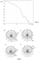
Figure 5 is a level vs. frequency diagram illustrating an exemplary theoretical rear attenuation over frequency for a cylindrical baffle. -
Figure 6 is a polar diagram illustrating the directivity of a tweeter built into a cylindrical baffle at 500 Hz, 1 KHz, 2 KHz and 3 KHz in comparison with a desired polar directivity. -
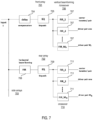
Figure 7 is a block diagram illustrating a signal processing structure implemented in a digital signal processor and configured to drive the loudspeakers of at least two loudspeaker arrays. -
Figure 8 is a schematic diagram illustrating via three different views a slim-tower generalized line array loudspeaker arrangement including three vertical arrays. -
Figure 9 is a level vs. frequency diagram illustrating frequency responses for various height offsets at a certain distance in the plane of the loudspeaker arrangement shown inFigure 8 versus a constant-beamwidth transducer target function for the combined front arrays. -
Figure 10 is a level vs. frequency diagram illustrating frequency responses for various height offsets at a certain distance in the plane of the loudspeaker arrangement shown inFigure 8 versus the constant-beamwidth transducer target function for the rear array. -
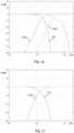
Figure 11 is a level vs. frequency diagram illustrating crossover transfer functions for the front array (combined front arrays) of the loudspeaker arrangement shown inFigure 8 . -
Figure 12 is a level vs. frequency diagram illustrating crossover transfer functions for the rear array of the loudspeaker arrangement shown inFigure 8 . -
Figure 13 is a schematic diagram illustrating an example loudspeaker arrangement with a minimum number of channels possible. -
Figure 14 is a level vs. frequency diagram illustrating vertical frequency responses of the front array of the loudspeaker arrangement shown inFigure 13 compared to curves provided by a constant-beamwidth transducer target function. -
Figure 15 is a level vs. frequency diagram illustrating vertical frequency responses of the rear array of the loudspeaker arrangement shown inFigure 13 compared to curves provided by a constant-beamwidth transducer target function. -
Figure 16 is a level vs. frequency diagram illustrating crossover transfer functions for the front array (combined front arrays) of the loudspeaker arrangement shown inFigure 13 . -
Figure 17 is a level vs. frequency diagram illustrating crossover transfer functions for the rear array of the loudspeaker arrangement shown inFigure 13 . -
Figure 18 includes two level vs. frequency diagrams illustrating frequency responses horizontally at 0°, 90° and 180° in the lower diagram of the loudspeaker arrangement shown inFigure 13 , and horizontal beam filter responses thereof in the upper diagram, as a result of an iteration process. - In order to control the vertical radiation pattern of a loudspeaker arrangement (herein also referred to as system) to be designed, a vertical beamforming crossover design is employed. It is desirable to combine a traditional loudspeaker array design having specialized (multiway) loudspeakers such as, for example, tweeters, midranges and woofers, with an array control technique such as, for example, a beamforming technique, so that not only the directivity and smoothness of out-of-axis responses, but also other requirements such as low distortion across the frequency band, efficiency and maximum sound power level at a given enclosure size can be satisfied.
- Some traditional array design techniques require identical wideband transducers across the array as described in R. Taylor, K. Manke, D.B. Keele, "Circular-Arc Line Arrays with Amplitude Shading for Constant Directivity". J. Audio Eng. Soc., Vol. 67, No. 6, June 2019, and M. Van der Wal, E. Start, D. De Vries, "Design of logarithmically spaced constant-directivity transducer arrays", J.A.E.S. Vol. 44 No. 6, June 1996. A linear-phase design technique for multiway loudspeakers as disclosed, for example, in
United States Patent US7991170 requires very tight spacing in the center, does not allow the use of large, powerful transducers, and demands low crossover frequencies, which may result in impaired power handling and low achievable loudness level. - These limitations are overcome with the design methods described herein. The designs provided by these methods are optimized for a prescribed listening distance D and a vertically and horizontally extending (only the vertical dimension is shown in
Figure 1 ) listening window having at the listening point a height (zero to H) measured from acenter axis 101 of anexemplary loudspeaker arrangement 102, as depicted inFigure 1 . The design methods presented herein are based on the following considerations: - Initially, the design of an array of multiple loudspeakers is determined in order to control vertical directivity. This array, herein referred to as "Generalized Line Array (GLA)", is largely unrestricted in terms of loudspeaker type (frequency range), number and spacing. Multiple (i.e., at least two) such arrays may be arranged in a common cabinet and combined with array filter sets to control horizontal responses and counteract diffraction. In the
exemplary loudspeaker arrangement 102 shown inFigures 1 and2 , which only depict a front array thereof,multiway loudspeakers 103, i.e., specialized loudspeakers such as tweeters, midranges and woofers, are arranged in acabinet 104 and array-wise in line with each other to form a front array, wherein the highest frequency loudspeakers are disposed close to or in the center, and the lowest frequency loudspeakers are close to the vertically opposing edges of theloudspeaker arrangement 102. As can be seen fromFigure 2 , not only one but also multiple (i.e., at least two) loudspeakers are allowed at each position, wherein the membrane diameters of the loudspeakers at each position are summed up. As shown, there may be, for example, a vertical arrangement of two transducers atposition 0 and horizontal arrangements of two transducers at vertical positions x 2, ... xDm. In the front array shown inFigure 2 , the two loudspeakers at each of vertical positions x2 , ... xDm are horizontally shifted by ±45° related to the position of the loudspeakers atvertical positions 0 and x 1. This results in convex (arc-shaped) distributions of theloudspeakers 103 around a vertical axis of thecabinet 104. Further, as the front side of thecabinet 104 is curved inwardly from the bottom to the top, there is a concave (arc-shaped) distribution of theloudspeakers 103 around a horizontal axis of thecabinet 104. - Driver placement may start with a "best guess" of loudspeaker choice and placement, e.g., symmetrical by a center tweeter at (not shown) or two center speakers (as shown) around a position zero (0), and with a definition of a vertical position vector X = [x 1 , ... xDm ], wherein Dm (e.g., Dm = 5) is the number of (pairs of) loudspeaker positions above and below zero, respectively. Further, as also shown in
Figure 2 , the respective membrane diameters of the loudspeakers are specified by a vector Q = [q 0 , q 1, ... qDm ], and the total number of loudspeaker positions is specified by M = 2Dm +1. - Constant-beamwidth transducers (CBT) are curved-surface transducers in the form of a spherical cap with frequency-independent Legendre shading, or as herein, Squared Cosine Shading that provides wide-band constant beamwidth and directivity behavior with virtually no side lobes. CBT arrays employ amplitude shading (gain factors) and geometrically realized delays (by means of an arc-shaped enclosure) to achieve a desired beam shape as detailed, for example, in R. Taylor, K. Manke, D.B. Keele, "Circular-Arc Line Arrays with Amplitude Shading for Constant Directivity". J. Audio Eng. Soc., Vol. 67, No. 6, June 2019. Logarithmic arrays are based on a bank of low pass filters as detailed, for example, in M. Van der Wal, E. Start, D. De Vries, "Design of logarithmically spaced constant-directivity transducer arrays", J.A.E.S. Vol. 44 No. 6, June 1996. Conventional loudspeaker crossover arrangements employ band pass filter designs having high passes and low passes.
- In the exemplary methods described herein, four parameters per loudspeaker channel (corresponding to a pair of loudspeaker positions) of an array, delays D1, levels W, frequency responses of high passes HHP and frequency responses of low passes HLP, are combined with each other to compose a set of crossover frequency responses Hc (i)=Dl(i)·W(i)HHP(i)·HLP (i), i=1...M, characterized by a delay vector dd=[dDm,...d1,0,d1,... dDm ], a level vector wd=[wDm,...w 1,1,w 1,...wDm ], a high pass corner frequency vector fd=[fDm,...f 1 , fo, f 1 ,...fDm ], and a low pass coefficient vector gd =[gDm,... g 1,0,g 1,... gDm ].
- From these parameters, individual (filter) frequency responses can be derived:
- a) Delays Dl(i,f) = e -j2πf/ c·di, i = 0 ... Dm, f = (1 .... N)/N·(fs/2), wherein c represents the speed of sound, fs represents a sample frequency, and N represents a number of discrete frequency sampling points.
- b) Levels W(i,f) =wi .
- c) High pass frequency responses H(fi,f) are, for example, magnitude frequency responses of Butterworth high passes of degree n and corner frequency fi. Other high pass crossover filters can be used as well, depending on choice of loudspeakers and overall filter design (Bessel, Tchebychev etc). Since the filter designs are linear-phase, the phase responses of the prototype high passes are discarded.
- d) Similar to logarithmic array designs described in M. Van der Wal, E. Start, D. De Vries, "Design of logarithmically spaced constant-directivity transducer arrays", J.A.E.S. Vol. 44 No. 6, June 1996, the low pass frequency responses are based on a window function, for example a Kaiser window WK (f, β). The parameter β is a fixed choice for the array design, and can be used to modify beam width. This results in low pass filter responsesĤLP(i,f), wherein
- A normalization is applied to the low pass filter responses ĤLP(i,f) to ensure that the sum of all low pass functions at a given frequency point is 1, which results in the normalized low pass frequency response HLP(i,f k ) according to:

-
Figure 3 depicts examples of the resulting low pass frequency responses as levels A [dB] vs. frequency f [Hz] of various low pass filters. - Acoustic frequency responses Db at L discrete points hi (also referred to as listening points) across the listening window having the height H can be computed according to hl=l·H/L, l=0...L. The loudspeakers (transducers) are modeled as vibrating circular pistons in a baffle:



- By applying a nonlinear optimization routine, the unknown filter parameters dd, wd, fd, gd can be determined at each frequency point, e.g., by minimizing an error e(f), wherein

- The CBT target frequency response HT is derived by computing target responses as a sum of Mc discrete point sources (e.g., loudspeakers) on the surface of the arc according to:
-

-

- wherein

-

- ra represents the arc radius.
- Other shading functions can be used as well as described in R. Taylor, K. Manke, D.B. Keele, "Circular-Arc Line Arrays with Amplitude Shading for Constant Directivity". J. Audio Eng. Soc., Vol. 67, No. 6, June 2019. The underlying nonlinear optimization problem can be solved with common software as, for example, the function "fmincon" (find minimum of constrained nonlinear multivariable function) of the MATLAB optimization toolbox. MATLAB is a proprietary multi-paradigm programming language and numeric computing environment developed by MathWorks. The function "fmincon" implements four different algorithms, which are the algorithms "interior point", "sequential quadratic programming (SQP)", "active set", and "trust region reflective", and which can be selected by a flag.
- In order to control the horizontal radiation pattern, a horizontal crossover design is obtained that includes multiple vertical arrays, pointing to different angular room directions. A vertical array is an array of loudspeakers that are vertically aligned. As an example, one front and one rear vertical array, are employed with, for example, a directivity target having the shape of a first order cardioid Pcardioid(β) = 0.5 + 0.5cos(β). Higher order directivity characteristics can be achieved by adding multiple side arrays.
- The following iterative design procedure is based on a set of combined frequency responses HDR (q,r,i) of all vertical arrays of the system at incremental angles (in a horizontal plane) around the cabinet, wherein q = 1, ... , Q is the angular index, r the array number, and i the frequency index. The system frequency responses at discrete angles q, U(q, i), can be computed as the complex sum of all sources, with (yet unknown) beamforming filters having frequency responses Cr(i) according to:

- Real-valued target frequency responses T(q,i) specify the desired horizontal system responses, for example, the above-mentioned first order cardioid function. A nonlinear optimization routine is applied at each frequency point that minimizes the error

- This bounded, nonlinear optimizations problem can be solved with standard software, for example the function "fmincon" of the Matlab optimization toolbox already mentioned above. The following bounds may be applied:
Gmax =20·log(max(|Cr |)), the maximum allowed filter level, and lower and upper limits for the magnitude values from one calculated frequency point to the next point, specified by an input parameter |Cr (i)|·(1-δ)<|Cr(i+1)|<|Cr(i)|·(1+δ), in order to control smoothness of the resulting frequency response. - A flow chart illustrating an example design method according to the disclosure presented above is shown in
Figure 4 . After going through a number of steps outlined below, a new iteration may be conducted if the result is not satisfactory. Transducer distances, and, as the case may be, the number of transducers and membrane sizes may be adapted before a new iteration round. The sequence of steps in the chart is exemplary and may vary as the case may be. - In a
first step 401, design start parameters are provided including a number of (vertical) loudspeaker arrays, a number of loudspeakers per array, distances between loudspeakers per array and loudspeaker membrane sizes per array. For example, an (initial) best guess of the loudspeaker arrangement is made by a designer. The (initial) best guess may be at least the number of vertical arrays, the number of loudspeakers per array, distances between loudspeakers in each array and membrane sizes in each array. Optional further parameters that may be included in the (initial) best guess may include at least one of orientation of the arrays, enclosure shape, and type of loudspeakers (specified by, e.g., at least one of frequency range, power, impedance). The initial best guess or subsequent best guesses may be adapted manually by a designer or automatically by, e.g., software, when an/another iteration round is initiated. - In a
second step 402, a loudspeaker arrangement is provided which is based on the design start parameters and which includes at least a vertical front array. For example, a prototype enclosure equipped with loudspeakers is provided based on the (initial) best guess of the loudspeaker arrangement according to thefirst step 401 or to the outcome of a previous iteration round. - In a
third step 403, the acoustic frequency responses of the loudspeaker arrangement are measured with any electronic filters, e.g., beamforming and crossover filters, connected upstream of the loudspeakers bypassed or omitted, and at predefined horizontal angle increments. - In a
fourth step 404, combined beam forming and crossover filter frequency responses for the vertical front array are computed based on the measured frequency responses of the loudspeaker arrangement and first target frequency responses at various frequency points and various positions. The first target frequency responses are constant-beam-width transducer target frequency responses that specify desired frequency responses of the loudspeaker array to be designed. For example, the frequency responses of front vertical beam forming crossover filters, which are filters that combine a beam forming filter and a crossover filter, e.g., in a single filter as shown inFigure 11 , and which are represented by the filter parameters dd, wd, fd, gd, are computed for an, e.g., full bandwidth front array based on CBT directivity target frequency responses such as, for example, in the way outlined above in connection with and based on the CBT directivity target frequency responses HT (l,f) and the measured acoustic frequency responses Hw (l,f) of the loudspeaker arrangement resulting from thethird step 403. - In an optional
fifth step 405, combined beam forming and crossover filter frequency responses for an optional vertical rear array are computed based on the measured frequency responses of the loudspeaker arrangement and the first target frequency responses at various frequency points and various positions in a manner similar to the one outlined above in connection with thefourth step 404. - In an optional
sixth step 406, combined beam forming and crossover filter frequency responses for optional vertical side arrays are computed based on the measured frequency responses of the loudspeaker arrangement and the first target frequency responses at various frequency points and various positions in a manner similar to the one outlined above in connection with thefourth step 404. - For example, frequency responses of rear vertical beam forming crossover filters are computed for a rear array based on the CBT directivity target frequency responses HT (l,f) and the resulting acoustic frequency responses Hw (l,f) of the rear array. Additionally, side beam-forming crossover filters may be designed in a similar manner for at least one optional side array based on the CBT directivity target function HT (l,f) and the measured acoustic frequency responses Hw (l,f) of the loudspeaker arrangement. Designing the filters for the rear array and the optional side array(s) includes computing frequency responses of the beam forming crossover filters to be designed, for example, in the way outlined above in connection with and based on the CBT directivity target frequency responses HT (l,f) and the measured acoustic frequency responses Hw (l,f) of the loudspeaker arrangement. It is noted that the bandwidth of the rear array or of the one or two optional side arrays or of rear and side array(s) may be reduced because sound diffracted around an enclosure experiences a natural attenuation at high frequencies in the form of shadowing. A level vs. frequency diagram illustrating an exemplary theoretical rear attenuation over frequency for a cylindrical baffle having a radius of ra = 0.125 m is shown in
Figure 5 . For example, attenuation at 3 KHz may be more than 20dB. Polar plots at 500 Hz, 1 KHz, 2 KHz and 3 KHz shown inFigure 6 for a 1" tweeter built into a cylindrical baffle of radius of ra = 0.125 m confirm this. As outlined, for example, in Earl. G. Williams, Fourier Acoustics, Academic Press, 1999, the far field sound pressure P at horizontal angles ϕ around a long cylinder of radius a, with a short, rectangular membrane of angular radius α built in as sound source, can be computed as follows:

Figure 5 and inFigure 6 ascurves 601, plotted againstcurves 602 representing a first order cardioid polar characteristic, which is the target of the design to be achieved, Pcardioid (ϕ) = 0.5 + 0.5cos(ϕ). - In a
seventh step 407, combined equalizing and crossover filter frequency responses for the vertical front array are computed based on second target frequency responses, the second target frequency responses being the combined beam forming and crossover filter frequency responses for the vertical front array, and the combined equalizing and crossover filter frequency responses being configured to obtain acoustic linear phase responses of the loudspeaker arrangement. The beam forming crossover filters from the fourth step 404 (andfifth step 405 and/or sixth step 406), which may be zero-phase except for the delay vector, are taken as target frequency responses to compute the frequency responses of combined equalizing and crossover filters, for example thefilters Figure 7 . The filters are computed as
- In an
eighth step 408, computing horizontal beam forming filter frequency responses is based on third target frequency responses (e.g., target frequency responses T(q,i) above). The third target frequency responses specify desired horizontal frequency responses of the loudspeaker array to be designed. For example, the horizontal beamforming filters Cr are implemented as FIR filters in full bandwidth. The second filter and all other filters are normalized to the first filter, yielding for example
filter 708 shown in and described below in connection withFigure 7 , wherein the first filter becomes a pure delay element, e.g.,delay element 704 inFigure 7 . - In an optional
ninth step 409, it is checked whether the achieved results are satisfactory. This may be performed by measuring the acoustic frequency responses of the loudspeaker arrangement involving all filters. - If the achieved results are satisfactory, in a
tenth step 410, the electronic filters are designed based on (e.g., computed from) the combined beam forming and crossover filter frequency responses for the vertical front array, the equalizing and crossover filter frequency responses, and the horizontal beam forming filter frequency responses. - If the achieved results are not satisfactory, in an optional
eleventh step 411, at least one of the design start parameters is changed and the steps 401-409 are repeated. - A block diagram of a signal processing structure implemented in a digital signal processor (DSP) and configured to drive the loudspeakers of at least two loudspeaker arrays is shown in
Figure 7 . A time-discrete input signal x is supplied to a frontarray signal path 701, a reararray signal path 702 and an optional side array path 703 (not shown in detail). The frontarray signal path 701 includes adelay element 704 for delay time compensation, a subsequent frequency equalizer 705 (e.g., implemented by way of a multiplicity of biquad filters) for frequency compensation, and a subsequent vertical beamforming / crossover network 706 (e.g., implemented as a bank of finite impulse response (FIR) filters 707). The reararray signal path 702 includes aFIR filter 708 for horizontal beamforming, a subsequent frequency equalizer 709 (e.g., implemented with a multiplicity of biquad filters) for frequency compensation, and a subsequent crossover network 710 (e.g., implemented as a bank of finite impulse response (FIR) filters 711). The outputs offilters 707 drive the center loudspeaker or the center pair of loudspeakers and the remaining pairs of loudspeakers of the front array. The outputs offilters 711 drive the center loudspeaker or the center pair of loudspeakers and the remaining pairs of loudspeakers of the rear array. Crossover filters and horizontal beam forming filters may be finite impulse response (FIR) filters of length 128 ... 512. - As an example,
Figure 8 shows three views A (front view), B (side view) and C (rear view) of a slim towerGLA loudspeaker arrangement 801, including threevertical arrays frontal arrays mutual tweeter section 805, and may be electrically connected in parallel. Twotweeters 806 are disposed in the center of thetweeter section 805 and, thus, theloudspeaker arrangement 801, and electrically connected in parallel. The distance between the twotweeters 806 is chosen such that the resulting vertical directivity matches the directivity of thewhole arrays Figure 9 shows frequency response plots 901 (level A [dB] vs. frequency f [Hz]) forheight offsets 0 ... H in nine linear steps, with, e.g., H = 0.9m and distance D = 2.5m (seeFigure 1 ) in the plane of theloudspeaker arrangement 801 plotted against theCBT target 902 for the combinedfront arrays Figure 10 respectiverear frequency plots 1002 versustarget functions 1002 for therear array 804, after nonlinear optimization. As can be seen, therear array 804 is only accurate up to about 3 KHz. The sound at higher frequencies may be suppressed because of sound shadowing, as explained above. - The combined
front arrays rear array 804 by five.Figures 11 and12 show the crossover transfer functions 1101-1106 (front) and 1201-1205 (rear) for the particular channels as level A [dB] vs. frequency f [Hz]. Compared to crossover transfer functions of a conventional loudspeaker, there is more overlap, which is needed to achieve the desired frequency-independent directivity characteristic. Parameters for the design shown inFigure 8 are for the front array: - Dm= 5,
- X = [0.62 0.42 0.25 0.14 0.069] [meter],
- Q = [0.083 0.065 0.047 0.047 0.034 0.073] [meter],
- dd=0 ,
- wd = [8.06 4.55 1.34 0.78 0.67 1 0.67 0.78 1.34 4.55 8.06],
- fd=[0 150 300 500 1800 3300 1800 500 300 150 0] [Hz], 4th order Butterworth, fixed,
- gd = [4.53 2.74 1.49 0.62 0.26 0 0.26 0.62 1.49 2.74 4.53],
- and for the rear array:
- Dm=4,
- X = [0.62 0.42 0.25 0.14] [meter],
- Q = [0.083 0.065 0.047 0.047 0.10] [meter],
- dd= 0,
- wd = [6.62 3.93 1.06 0.42 1 0.42 1.06 3.93 6.62],
- fd = [0 150 300 500 2000 500 300 150 0] [Hz], 4th order Butterworth, fixed,
- gd = [4.39 2.96 1.54 0.31 0 0.31 1.54 2.96 4.39].
- An example configuration with the minimum number of loudspeaker channels possible, but which is still in accordance with this disclosure, is shown in
Figure 13 . It includes a compact, bookshelftype loudspeaker arrangement 1301 with a three-channel front array 1301 (view A) and a two-channel rear array 1302 (view B). Thefront array 1301 includes threetweeters 1303 in the center of thefront array 1301 and twowoofers 1304 distant from this center. Therear array 1302 includes a midrange 1306 in the center of therear array 1302 and twowoofers 1304 distant from this center. The corresponding vertical frequency response plots with 1402 (front array) and 1502 (rear array) versus CBT targets 1401 (front array) and 1501 (rear array) are shown inFigures 14 (front array) and 15 (rear array), the corresponding crossover responses 1601-1603 (front array) and 1701 and 1702 (rear) are shown inFigures 16 (front array) and 17 (rear array). -
Figure 18 depicts frequency responses (level A [dB] vs. frequency f [Hz]) horizontally at 0°, 90° and 180° (see lower diagram) of aloudspeaker front array 1301, the horizontal beam filter responses of which are shown in the upper diagram, as a result of an iteration process as described above in connection with the horizontal beamforming crossover design. As predicted, there is more than 20dB attenuation of the rear filter response above 3 KHz. The design parameters are - for the front array 1301:
- Dm =2,
- X = [0.12 0.045] [meter],
- Q = [0.08 0.025 0.025] [meter],
- dd = 0,
- wd = [1.82 0.56 1 0.56 1.82],
- fd = [0 1500 4000 1500 0] [Hz], 4th order Butterworth, fixed,
- gd = [1.2 0.24 0 0.24 1.2],
- Dm = 1 ,
- X = [0.14] [meter],
- Q = [0.08 0.04] [meter],
- dd = 0,
- wd = [0.77 1 0.77],
- fd = [0 1200 0] [Hz], 4th order BW, fixed,
- gd = [1.0 0 1.0]
- The method may be implemented partly by software and/or firmware stored on or in a computer-readable medium, machine-readable medium, propagated-signal medium, and/or signal-bearing medium. The media may comprise any device that contains, stores, communicates, propagates, or transports executable instructions for use by or in connection with an instruction executable system, apparatus, or device. The machine-readable medium may selectively be, but is not limited to, an electronic, magnetic, optical, electromagnetic, or infrared signal or a semiconductor system, apparatus, device, or propagation medium.
- The systems may include additional or different logic and may be implemented in many different ways, e.g., as a microprocessor, microcontroller, application specific integrated circuit (ASIC), discrete logic, or a combination of other types of circuits or logic. Similarly, memories may be DRAM, SRAM, Flash, or other types of memory. Parameters (e.g., conditions and thresholds) and other data structures may be separately stored and managed, may be incorporated into a single memory or database, or may be logically and physically organized in many different ways. Programs and instruction sets may be parts of a single program, separate programs, or distributed across several memories and processors.
- The description of embodiments has been presented for purposes of illustration and description. Suitable modifications and variations to the embodiments may be performed in light of the above description or may be acquired from practicing the methods. For example, unless otherwise noted, one or more of the described methods may be performed by a suitable device and/or combination of devices. The described methods and associated actions may also be performed in various orders in addition to the order described in this application, in parallel, and/or simultaneously. The described systems are exemplary in nature, and may include additional elements and/or omit elements.
- As used in this application, an element or step recited in the singular and proceeded with the word "a" or "an" should be understood as not excluding plural of said elements or steps, unless such exclusion is stated. Furthermore, references to "one embodiment" or "one example" of the present disclosure are not intended to be interpreted as excluding the existence of additional embodiments that also incorporate the recited features. The terms "first," "second," and "third," etc. are used merely as labels, and are not intended to impose numerical requirements or a particular positional order on their obj ects.
- While various embodiments of the invention have been described, it will be apparent to those of ordinary skilled in the art that many more embodiments and implementations are possible within the scope of the invention. In particular, the skilled person will recognize the interchangeability of various features from different embodiments. Although these techniques and systems have been disclosed in the context of certain embodiments and examples, it will be understood that these techniques and systems may be extended beyond the specifically disclosed embodiments to other embodiments and/or uses and obvious modifications thereof.

Claims (14)
- A method for designing a line array loudspeaker arrangement, the loudspeaker arrangement comprising electronic filters and a loudspeaker enclosure equipped with loudspeakers that are connected downstream of the filters, have a membrane and are arranged to form at least one array; the method comprising:providing design start parameters including a number of loudspeaker arrays, a number of loudspeakers per array, distances between loudspeakers per array and loudspeaker membrane sizes per array;providing a loudspeaker arrangement based on the design start parameters and including at least a vertical front array,measuring the frequency responses of the loudspeaker arrangement with bypassed or omitted electronic filters at predefined horizontal angle increments;computing combined beam forming and crossover filter frequency responses for the vertical front array based on the measured frequency responses of the loudspeaker arrangement and first target frequency responses at various frequency points and various positions, the first target frequency responses being constant-beam-width transducer target frequency responses that specify desired frequency responses of the loudspeaker array to be designed;computing combined equalizing and crossover filter frequency responses for the vertical front array based on second target frequency responses, the second target frequency responses being the combined beam forming and crossover filter frequency responses for the vertical front array, and the combined equalizing and crossover filter frequency responses being configured to obtain acoustic linear phase responses of the loudspeaker arrangement;computing horizontal beam forming filter frequency responses based on third target frequency responses, the third target frequency responses specify desired horizontal frequency responses of the loudspeaker array to be designed; anddesigning the electronic filters based on the combined beam forming and crossover filter frequency responses for the vertical front array, the equalizing and crossover filter frequency responses, and the horizontal beam forming filter frequency responses.
- The method of claim 1, wherein the line array loudspeaker arrangement further comprises a vertical rear array, the method further comprising computing beam forming and crossover filter responses for the vertical rear array based on the measured frequency responses of the loudspeaker arrangement and the first target frequency responses at various frequency points and various positions.
- The method of claim 1 or 2, wherein the line array loudspeaker arrangement further comprises at least one vertical side array, the method further comprising computing beam forming and crossover filter responses for the at least one vertical side array based on the measured frequency responses of the loudspeaker arrangement and the first target frequency responses at various frequency points and various positions.
- The method of any of claims 1-3, further comprising changing at least one of the design start parameters and repeating at least: providing the loudspeaker arrangement, measuring the frequency responses of the loudspeaker arrangement, computing the combined beam forming and crossover filter responses for the vertical front array, computing the combined equalizing and crossover filter frequency responses for the vertical front array, and computing the horizontal beam forming filter frequency responses.
- The method of any of claims 1-4, wherein the design start parameters further include at least one of number of vertical arrays, orientation of arrays, shape of enclosure, and type of loudspeaker.
- The method of any of claims 1-5, wherein computing the combined beam forming and crossover filter frequency responses for the vertical front array is performed over full operation bandwidth of the loudspeaker array.
- The method of any of claims 1-6, wherein at least one of: computing the beam forming and crossover filter responses for the vertical rear array and computing the beam forming and crossover filter responses for the at least one vertical side array is performed with a bandwidth smaller than the full operation bandwidth of the loudspeaker array.
- The method of any of claims 1-7, wherein the constant-beam-width transducer directivity target is derived by computing a sum of a number of discrete point sources on a surface of an arc.
- The method of claim 8, wherein the constant-beam-width transducer directivity target is dependent on a shading function.
- The method of any of claims 1-9, wherein at least one of computing the first vertical beam forming crossover filter parameters for the front array, and computing second vertical beam forming crossover filter parameters for the rear array comprises a optimization procedure minimizing at each frequency point a first error that corresponds with the difference between the measured frequency response of the loudspeaker arrangement and the constant-beam-width transducer directivity target frequency responses.
- The method of any of claims 1-10, wherein the optimization procedure is non-linear.
- The method of any of claims 1-11, wherein the acoustic frequency responses of the loudspeaker arrangement is the complex sum of the frequency responses of all loudspeakers at different angles.
- The method of any of claims 1-12, wherein computing the horizontal beam forming filter frequency responses comprises a non-linear optimization by minimizing at each frequency point a second error that corresponds with the difference between the measured frequency response of the loudspeaker arrangement and the third target frequency responses at predefined horizontal angle increments.
- The method of any of claims 1-13, wherein the various positions at which the combined beam forming and crossover filter frequency responses for the vertical front array are computed are within a vertically and horizontally extending listening window at a listening distance from a center of the loudspeaker arrangement.
Priority Applications (3)
| Application Number | Priority Date | Filing Date | Title |
|---|---|---|---|
| EP21191526.9A EP4138412B1 (en) | 2021-08-16 | 2021-08-16 | A method for designing a line array loudspeaker arrangement |
| CN202210840752.3A CN115706888A (en) | 2021-08-16 | 2022-07-18 | Method for designing a line array loudspeaker arrangement |
| US17/881,002 US12089017B2 (en) | 2021-08-16 | 2022-08-04 | Method for designing a line array loudspeaker arrangement |
Applications Claiming Priority (1)
| Application Number | Priority Date | Filing Date | Title |
|---|---|---|---|
| EP21191526.9A EP4138412B1 (en) | 2021-08-16 | 2021-08-16 | A method for designing a line array loudspeaker arrangement |
Publications (2)
| Publication Number | Publication Date |
|---|---|
| EP4138412A1 true EP4138412A1 (en) | 2023-02-22 |
| EP4138412B1 EP4138412B1 (en) | 2025-05-14 |
Family
ID=77367256
Family Applications (1)
| Application Number | Title | Priority Date | Filing Date |
|---|---|---|---|
| EP21191526.9A Active EP4138412B1 (en) | 2021-08-16 | 2021-08-16 | A method for designing a line array loudspeaker arrangement |
Country Status (3)
| Country | Link |
|---|---|
| US (1) | US12089017B2 (en) |
| EP (1) | EP4138412B1 (en) |
| CN (1) | CN115706888A (en) |
Families Citing this family (2)
| Publication number | Priority date | Publication date | Assignee | Title |
|---|---|---|---|---|
| US20260052336A1 (en) * | 2022-08-10 | 2026-02-19 | Pascal A/S | A constant beamwidth loudspeaker |
| WO2025242278A1 (en) | 2024-05-20 | 2025-11-27 | Harman Becker Automotive Systems Gmbh | System and method for sound field control with a spherical loudspeaker |
Citations (2)
| Publication number | Priority date | Publication date | Assignee | Title |
|---|---|---|---|---|
| US7991170B2 (en) | 2005-05-05 | 2011-08-02 | Harman International Industries, Incorporated | Loudspeaker crossover filter |
| WO2018045133A1 (en) * | 2016-08-31 | 2018-03-08 | Harman International Industries, Incorporated | Variable acoustics loudspeaker |
Family Cites Families (23)
| Publication number | Priority date | Publication date | Assignee | Title |
|---|---|---|---|---|
| USD262793S (en) | 1979-09-11 | 1982-01-26 | Epicure Products, Inc. | Loudspeaker |
| US4289929A (en) | 1979-09-11 | 1981-09-15 | Epicure Products, Inc. | Loudspeaker and enclosure combination |
| USD394860S (en) | 1995-06-19 | 1998-06-02 | James Phillip Kitsmiller | Audio speaker housing |
| USD391962S (en) | 1995-11-21 | 1998-03-10 | Martin Borys | Loudspeaker |
| USD466885S1 (en) | 2001-10-20 | 2002-12-10 | New Transducers Limited | Loudspeaker |
| USD471888S1 (en) | 2002-07-30 | 2003-03-18 | Harman International Industries, Inc. | Speaker housing |
| USD491918S1 (en) | 2003-05-06 | 2004-06-22 | Harman International Industries, Incorporated | Loudspeaker |
| JP4779381B2 (en) * | 2005-02-25 | 2011-09-28 | ヤマハ株式会社 | Array speaker device |
| US7804972B2 (en) * | 2006-05-12 | 2010-09-28 | Cirrus Logic, Inc. | Method and apparatus for calibrating a sound beam-forming system |
| EP1986464A1 (en) * | 2007-04-27 | 2008-10-29 | Technische Universiteit Delft | Highly directive endfire loudspeaker array |
| USD595263S1 (en) | 2008-10-18 | 2009-06-30 | Peigen Jiang | Loudspeaker |
| USD754099S1 (en) | 2014-01-14 | 2016-04-19 | Samsung Electronics Co., Ltd. | Speaker |
| CN115348492A (en) | 2014-08-18 | 2022-11-15 | 苹果公司 | Rotationally symmetric loudspeaker array |
| DE102015203600B4 (en) * | 2014-08-22 | 2021-10-21 | Fraunhofer-Gesellschaft zur Förderung der angewandten Forschung e.V. | FIR filter coefficient calculation for beamforming filters |
| USD758347S1 (en) | 2014-08-29 | 2016-06-07 | Yamaha Corporation | Speaker with lighting |
| US9749747B1 (en) | 2015-01-20 | 2017-08-29 | Apple Inc. | Efficient system and method for generating an audio beacon |
| USD798931S1 (en) | 2015-11-26 | 2017-10-03 | Lg Electronics Inc. | Surveillance camera |
| EP3193514B1 (en) * | 2016-01-13 | 2019-07-24 | VLSI Solution Oy | A method and apparatus for adjusting a cross-over frequency of a loudspeaker |
| JP2017152857A (en) | 2016-02-23 | 2017-08-31 | 国立大学法人電気通信大学 | Filter coefficient determination device, filter coefficient determination method, program, and reproduction system |
| USD838690S1 (en) | 2016-07-29 | 2019-01-22 | Lg Electronics Inc. | Wireless speaker |
| USD842903S1 (en) | 2017-04-19 | 2019-03-12 | Shenzhen Teana Technology Co., Ltd. | Karaoke device |
| USD853354S1 (en) | 2017-08-31 | 2019-07-09 | Harman International Industries, Incorporated | Loudspeaker |
| US10893363B2 (en) * | 2018-09-28 | 2021-01-12 | Apple Inc. | Self-equalizing loudspeaker system |
-
2021
- 2021-08-16 EP EP21191526.9A patent/EP4138412B1/en active Active
-
2022
- 2022-07-18 CN CN202210840752.3A patent/CN115706888A/en active Pending
- 2022-08-04 US US17/881,002 patent/US12089017B2/en active Active
Patent Citations (2)
| Publication number | Priority date | Publication date | Assignee | Title |
|---|---|---|---|---|
| US7991170B2 (en) | 2005-05-05 | 2011-08-02 | Harman International Industries, Incorporated | Loudspeaker crossover filter |
| WO2018045133A1 (en) * | 2016-08-31 | 2018-03-08 | Harman International Industries, Incorporated | Variable acoustics loudspeaker |
Non-Patent Citations (4)
| Title |
|---|
| EARL. G. WILLIAMS: "Fourier Acoustics", 1999, ACADEMIC PRESS |
| M. VAN DER WALE. STARTD. DE VRIES: "Design of logarithmically spaced constant-directivity transducer arrays", J.A.E.S., vol. 44, no. 6, June 1996 (1996-06-01), XP000721403 |
| R. TAYLORK. MANKED.B. KEELE: "Circular-Arc Line Arrays with Amplitude Shading for Constant Directivity", J. AUDIO ENG. SOC., vol. 67, no. 6, June 2019 (2019-06-01), XP040706693 |
| TAYLOR RICHARD ET AL: "Circular-Arc Line Arrays with Amplitude Shading for Constant Directivity", JAES, AES, 60 EAST 42ND STREET, ROOM 2520 NEW YORK 10165-2520, USA, vol. 67, no. 6, 9 June 2019 (2019-06-09), pages 400 - 413, XP040706693 * |
Also Published As
| Publication number | Publication date |
|---|---|
| US20230050161A1 (en) | 2023-02-16 |
| US12089017B2 (en) | 2024-09-10 |
| CN115706888A (en) | 2023-02-17 |
| EP4138412B1 (en) | 2025-05-14 |
Similar Documents
| Publication | Publication Date | Title |
|---|---|---|
| US8194868B2 (en) | Loudspeaker system for virtual sound synthesis | |
| EP1560460B1 (en) | Linear array loudspeaker and method for positioning of transducers | |
| US10805720B2 (en) | Audio signal processing apparatus and a sound emission apparatus | |
| US10667071B2 (en) | Low complexity multi-channel smart loudspeaker with voice control | |
| US20130058505A1 (en) | Circular loudspeaker array with controllable directivity | |
| US20080247565A1 (en) | Position-Independent Microphone System | |
| EP3507992B1 (en) | Variable acoustics loudspeaker | |
| US12089017B2 (en) | Method for designing a line array loudspeaker arrangement | |
| Albertini et al. | Two-stage beamforming with arbitrary planar arrays of differential microphone array units | |
| EP1986464A1 (en) | Highly directive endfire loudspeaker array | |
| Jin et al. | Design of optimal linear differential microphone arrays based array geometry optimization | |
| Frank et al. | Constant-beamwidth kronecker product beamforming with nonuniform planar arrays | |
| US10244317B2 (en) | Beamforming array utilizing ring radiator loudspeakers and digital signal processing (DSP) optimization of a beamforming array | |
| Mabande et al. | Towards superdirective beamforming with loudspeaker arrays | |
| Borra et al. | Arrays of first-order steerable differential microphones | |
| Keele Jr | Full-sphere sound field of constant-beamwidth transducer (CBT) loudspeaker line arrays | |
| Zhang et al. | Selective frequency invariant uniform circular broadband beamformer | |
| US7991170B2 (en) | Loudspeaker crossover filter | |
| Zotter et al. | Higher-order ambisonic microphones and the wave equation (linear, lossless) | |
| Kelly et al. | A highly directional loudspeaker for surround channel soundbar reproduction | |
| Shaiek et al. | Optimizing the directivity of multiway loudspeaker systems | |
| Blanco Galindo et al. | Robust hypercardioid synthesis for spatial audio capture: microphone geometry, directivity and regularization | |
| Galindo et al. | Robust hypercardioid synthesis for spatial audio capture: microphone geometry, directivity and robustness | |
| Jarrett et al. | Acoustic Parameter Estimation | |
| Merilaid | Real-time implementation of non-linear signal-dependent acoustic beamforming |
Legal Events
| Date | Code | Title | Description |
|---|---|---|---|
| PUAI | Public reference made under article 153(3) epc to a published international application that has entered the european phase |
Free format text: ORIGINAL CODE: 0009012 |
|
| STAA | Information on the status of an ep patent application or granted ep patent |
Free format text: STATUS: THE APPLICATION HAS BEEN PUBLISHED |
|
| AK | Designated contracting states |
Kind code of ref document: A1 Designated state(s): AL AT BE BG CH CY CZ DE DK EE ES FI FR GB GR HR HU IE IS IT LI LT LU LV MC MK MT NL NO PL PT RO RS SE SI SK SM TR |
|
| STAA | Information on the status of an ep patent application or granted ep patent |
Free format text: STATUS: REQUEST FOR EXAMINATION WAS MADE |
|
| 17P | Request for examination filed |
Effective date: 20230822 |
|
| RBV | Designated contracting states (corrected) |
Designated state(s): AL AT BE BG CH CY CZ DE DK EE ES FI FR GB GR HR HU IE IS IT LI LT LU LV MC MK MT NL NO PL PT RO RS SE SI SK SM TR |
|
| GRAP | Despatch of communication of intention to grant a patent |
Free format text: ORIGINAL CODE: EPIDOSNIGR1 |
|
| STAA | Information on the status of an ep patent application or granted ep patent |
Free format text: STATUS: GRANT OF PATENT IS INTENDED |
|
| INTG | Intention to grant announced |
Effective date: 20250213 |
|
| GRAS | Grant fee paid |
Free format text: ORIGINAL CODE: EPIDOSNIGR3 |
|
| GRAA | (expected) grant |
Free format text: ORIGINAL CODE: 0009210 |
|
| STAA | Information on the status of an ep patent application or granted ep patent |
Free format text: STATUS: THE PATENT HAS BEEN GRANTED |
|
| AK | Designated contracting states |
Kind code of ref document: B1 Designated state(s): AL AT BE BG CH CY CZ DE DK EE ES FI FR GB GR HR HU IE IS IT LI LT LU LV MC MK MT NL NO PL PT RO RS SE SI SK SM TR |
|
| P01 | Opt-out of the competence of the unified patent court (upc) registered |
Free format text: CASE NUMBER: APP_17037/2025 Effective date: 20250408 |
|
| REG | Reference to a national code |
Ref country code: GB Ref legal event code: FG4D |
|
| REG | Reference to a national code |
Ref country code: CH Ref legal event code: EP |
|
| REG | Reference to a national code |
Ref country code: IE Ref legal event code: FG4D |
|
| REG | Reference to a national code |
Ref country code: DE Ref legal event code: R096 Ref document number: 602021030706 Country of ref document: DE |
|
| REG | Reference to a national code |
Ref country code: NL Ref legal event code: MP Effective date: 20250514 |
|
| PG25 | Lapsed in a contracting state [announced via postgrant information from national office to epo] |
Ref country code: FI Free format text: LAPSE BECAUSE OF FAILURE TO SUBMIT A TRANSLATION OF THE DESCRIPTION OR TO PAY THE FEE WITHIN THE PRESCRIBED TIME-LIMIT Effective date: 20250514 Ref country code: PT Free format text: LAPSE BECAUSE OF FAILURE TO SUBMIT A TRANSLATION OF THE DESCRIPTION OR TO PAY THE FEE WITHIN THE PRESCRIBED TIME-LIMIT Effective date: 20250915 Ref country code: ES Free format text: LAPSE BECAUSE OF FAILURE TO SUBMIT A TRANSLATION OF THE DESCRIPTION OR TO PAY THE FEE WITHIN THE PRESCRIBED TIME-LIMIT Effective date: 20250514 |
|
| PGFP | Annual fee paid to national office [announced via postgrant information from national office to epo] |
Ref country code: DE Payment date: 20250724 Year of fee payment: 5 |
|
| REG | Reference to a national code |
Ref country code: LT Ref legal event code: MG9D |
|
| PG25 | Lapsed in a contracting state [announced via postgrant information from national office to epo] |
Ref country code: GR Free format text: LAPSE BECAUSE OF FAILURE TO SUBMIT A TRANSLATION OF THE DESCRIPTION OR TO PAY THE FEE WITHIN THE PRESCRIBED TIME-LIMIT Effective date: 20250815 Ref country code: NO Free format text: LAPSE BECAUSE OF FAILURE TO SUBMIT A TRANSLATION OF THE DESCRIPTION OR TO PAY THE FEE WITHIN THE PRESCRIBED TIME-LIMIT Effective date: 20250814 |
|
| PG25 | Lapsed in a contracting state [announced via postgrant information from national office to epo] |
Ref country code: NL Free format text: LAPSE BECAUSE OF FAILURE TO SUBMIT A TRANSLATION OF THE DESCRIPTION OR TO PAY THE FEE WITHIN THE PRESCRIBED TIME-LIMIT Effective date: 20250514 Ref country code: PL Free format text: LAPSE BECAUSE OF FAILURE TO SUBMIT A TRANSLATION OF THE DESCRIPTION OR TO PAY THE FEE WITHIN THE PRESCRIBED TIME-LIMIT Effective date: 20250514 |
|
| REG | Reference to a national code |
Ref country code: AT Ref legal event code: MK05 Ref document number: 1795833 Country of ref document: AT Kind code of ref document: T Effective date: 20250514 |
|
| PG25 | Lapsed in a contracting state [announced via postgrant information from national office to epo] |
Ref country code: BG Free format text: LAPSE BECAUSE OF FAILURE TO SUBMIT A TRANSLATION OF THE DESCRIPTION OR TO PAY THE FEE WITHIN THE PRESCRIBED TIME-LIMIT Effective date: 20250514 |
|
| PGFP | Annual fee paid to national office [announced via postgrant information from national office to epo] |
Ref country code: GB Payment date: 20250725 Year of fee payment: 5 |
|
| PG25 | Lapsed in a contracting state [announced via postgrant information from national office to epo] |
Ref country code: HR Free format text: LAPSE BECAUSE OF FAILURE TO SUBMIT A TRANSLATION OF THE DESCRIPTION OR TO PAY THE FEE WITHIN THE PRESCRIBED TIME-LIMIT Effective date: 20250514 |
|
| PG25 | Lapsed in a contracting state [announced via postgrant information from national office to epo] |
Ref country code: AT Free format text: LAPSE BECAUSE OF FAILURE TO SUBMIT A TRANSLATION OF THE DESCRIPTION OR TO PAY THE FEE WITHIN THE PRESCRIBED TIME-LIMIT Effective date: 20250514 |
|
| PG25 | Lapsed in a contracting state [announced via postgrant information from national office to epo] |
Ref country code: RS Free format text: LAPSE BECAUSE OF FAILURE TO SUBMIT A TRANSLATION OF THE DESCRIPTION OR TO PAY THE FEE WITHIN THE PRESCRIBED TIME-LIMIT Effective date: 20250814 |
|
| PG25 | Lapsed in a contracting state [announced via postgrant information from national office to epo] |
Ref country code: IS Free format text: LAPSE BECAUSE OF FAILURE TO SUBMIT A TRANSLATION OF THE DESCRIPTION OR TO PAY THE FEE WITHIN THE PRESCRIBED TIME-LIMIT Effective date: 20250914 |
|
| PG25 | Lapsed in a contracting state [announced via postgrant information from national office to epo] |
Ref country code: LV Free format text: LAPSE BECAUSE OF FAILURE TO SUBMIT A TRANSLATION OF THE DESCRIPTION OR TO PAY THE FEE WITHIN THE PRESCRIBED TIME-LIMIT Effective date: 20250514 |
|
| PG25 | Lapsed in a contracting state [announced via postgrant information from national office to epo] |
Ref country code: DK Free format text: LAPSE BECAUSE OF FAILURE TO SUBMIT A TRANSLATION OF THE DESCRIPTION OR TO PAY THE FEE WITHIN THE PRESCRIBED TIME-LIMIT Effective date: 20250514 Ref country code: SM Free format text: LAPSE BECAUSE OF FAILURE TO SUBMIT A TRANSLATION OF THE DESCRIPTION OR TO PAY THE FEE WITHIN THE PRESCRIBED TIME-LIMIT Effective date: 20250514 |
|
| PG25 | Lapsed in a contracting state [announced via postgrant information from national office to epo] |
Ref country code: CZ Free format text: LAPSE BECAUSE OF FAILURE TO SUBMIT A TRANSLATION OF THE DESCRIPTION OR TO PAY THE FEE WITHIN THE PRESCRIBED TIME-LIMIT Effective date: 20250514 |
|
| PG25 | Lapsed in a contracting state [announced via postgrant information from national office to epo] |
Ref country code: EE Free format text: LAPSE BECAUSE OF FAILURE TO SUBMIT A TRANSLATION OF THE DESCRIPTION OR TO PAY THE FEE WITHIN THE PRESCRIBED TIME-LIMIT Effective date: 20250514 |
|
| PG25 | Lapsed in a contracting state [announced via postgrant information from national office to epo] |
Ref country code: SK Free format text: LAPSE BECAUSE OF FAILURE TO SUBMIT A TRANSLATION OF THE DESCRIPTION OR TO PAY THE FEE WITHIN THE PRESCRIBED TIME-LIMIT Effective date: 20250514 |
|
| PG25 | Lapsed in a contracting state [announced via postgrant information from national office to epo] |
Ref country code: IT Free format text: LAPSE BECAUSE OF FAILURE TO SUBMIT A TRANSLATION OF THE DESCRIPTION OR TO PAY THE FEE WITHIN THE PRESCRIBED TIME-LIMIT Effective date: 20250514 |
|
| PG25 | Lapsed in a contracting state [announced via postgrant information from national office to epo] |
Ref country code: RO Free format text: LAPSE BECAUSE OF FAILURE TO SUBMIT A TRANSLATION OF THE DESCRIPTION OR TO PAY THE FEE WITHIN THE PRESCRIBED TIME-LIMIT Effective date: 20250514 |
|
| REG | Reference to a national code |
Ref country code: DE Ref legal event code: R097 Ref document number: 602021030706 Country of ref document: DE |
|
| PLBE | No opposition filed within time limit |
Free format text: ORIGINAL CODE: 0009261 |
|
| STAA | Information on the status of an ep patent application or granted ep patent |
Free format text: STATUS: NO OPPOSITION FILED WITHIN TIME LIMIT |
|
| REG | Reference to a national code |
Ref country code: CH Ref legal event code: H13 Free format text: ST27 STATUS EVENT CODE: U-0-0-H10-H13 (AS PROVIDED BY THE NATIONAL OFFICE) Effective date: 20260324 |
|
| REG | Reference to a national code |
Ref country code: CH Ref legal event code: L10 Free format text: ST27 STATUS EVENT CODE: U-0-0-L10-L00 (AS PROVIDED BY THE NATIONAL OFFICE) Effective date: 20260325 |
|
| PG25 | Lapsed in a contracting state [announced via postgrant information from national office to epo] |
Ref country code: MC Free format text: LAPSE BECAUSE OF FAILURE TO SUBMIT A TRANSLATION OF THE DESCRIPTION OR TO PAY THE FEE WITHIN THE PRESCRIBED TIME-LIMIT Effective date: 20250514 |
|
| PG25 | Lapsed in a contracting state [announced via postgrant information from national office to epo] |
Ref country code: LU Free format text: LAPSE BECAUSE OF NON-PAYMENT OF DUE FEES Effective date: 20250816 |
|
| 26N | No opposition filed |
Effective date: 20260217 |
|
| PG25 | Lapsed in a contracting state [announced via postgrant information from national office to epo] |
Ref country code: CH Free format text: LAPSE BECAUSE OF NON-PAYMENT OF DUE FEES Effective date: 20250831 |
|
| REG | Reference to a national code |
Ref country code: BE Ref legal event code: MM Effective date: 20250831 |
|
| PG25 | Lapsed in a contracting state [announced via postgrant information from national office to epo] |
Ref country code: LT Free format text: LAPSE BECAUSE OF FAILURE TO SUBMIT A TRANSLATION OF THE DESCRIPTION OR TO PAY THE FEE WITHIN THE PRESCRIBED TIME-LIMIT Effective date: 20250514 |
|
| PG25 | Lapsed in a contracting state [announced via postgrant information from national office to epo] |
Ref country code: IE Free format text: LAPSE BECAUSE OF NON-PAYMENT OF DUE FEES Effective date: 20250816 Ref country code: BE Free format text: LAPSE BECAUSE OF NON-PAYMENT OF DUE FEES Effective date: 20250831 |
|
| PG25 | Lapsed in a contracting state [announced via postgrant information from national office to epo] |
Ref country code: FR Free format text: LAPSE BECAUSE OF NON-PAYMENT OF DUE FEES Effective date: 20250831 |
|
| PG25 | Lapsed in a contracting state [announced via postgrant information from national office to epo] |
Ref country code: SE Free format text: LAPSE BECAUSE OF FAILURE TO SUBMIT A TRANSLATION OF THE DESCRIPTION OR TO PAY THE FEE WITHIN THE PRESCRIBED TIME-LIMIT Effective date: 20250514 |