EP1560460B1 - Linear array loudspeaker and method for positioning of transducers - Google Patents
Linear array loudspeaker and method for positioning of transducers Download PDFInfo
- Publication number
- EP1560460B1 EP1560460B1 EP04028748A EP04028748A EP1560460B1 EP 1560460 B1 EP1560460 B1 EP 1560460B1 EP 04028748 A EP04028748 A EP 04028748A EP 04028748 A EP04028748 A EP 04028748A EP 1560460 B1 EP1560460 B1 EP 1560460B1
- Authority
- EP
- European Patent Office
- Prior art keywords
- drivers
- loudspeaker
- center
- driver
- frequency
- Prior art date
- Legal status (The legal status is an assumption and is not a legal conclusion. Google has not performed a legal analysis and makes no representation as to the accuracy of the status listed.)
- Expired - Lifetime
Links
Images


Classifications
-
- H—ELECTRICITY
- H04—ELECTRIC COMMUNICATION TECHNIQUE
- H04R—LOUDSPEAKERS, MICROPHONES, GRAMOPHONE PICK-UPS OR LIKE ACOUSTIC ELECTROMECHANICAL TRANSDUCERS; ELECTRIC HEARING AIDS; PUBLIC ADDRESS SYSTEMS
- H04R25/00—Electric hearing aids
- H04R25/40—Arrangements for obtaining a desired directivity characteristic
- H04R25/405—Arrangements for obtaining a desired directivity characteristic by combining a plurality of transducers
-
- H—ELECTRICITY
- H04—ELECTRIC COMMUNICATION TECHNIQUE
- H04R—LOUDSPEAKERS, MICROPHONES, GRAMOPHONE PICK-UPS OR LIKE ACOUSTIC ELECTROMECHANICAL TRANSDUCERS; ELECTRIC HEARING AIDS; PUBLIC ADDRESS SYSTEMS
- H04R1/00—Details of transducers, loudspeakers or microphones
- H04R1/20—Arrangements for obtaining desired frequency or directional characteristics
- H04R1/22—Arrangements for obtaining desired frequency or directional characteristics for obtaining desired frequency characteristic only
- H04R1/26—Spatial arrangements of separate transducers responsive to two or more frequency ranges
-
- H—ELECTRICITY
- H04—ELECTRIC COMMUNICATION TECHNIQUE
- H04R—LOUDSPEAKERS, MICROPHONES, GRAMOPHONE PICK-UPS OR LIKE ACOUSTIC ELECTROMECHANICAL TRANSDUCERS; ELECTRIC HEARING AIDS; PUBLIC ADDRESS SYSTEMS
- H04R5/00—Stereophonic arrangements
- H04R5/02—Spatial or constructional arrangements of loudspeakers
Definitions
- This invention generally relates to a multi-way loudspeaker system and in particular to a multi-way loudspeaker system comprised of an array of multiple drivers capable of achieving high-quality sound.
- High-quality loudspeakers for the audio frequency ranges generally employ multiple specialized drivers for dedicated parts of the audio frequency band, such as tweeters (generally 2kHz-20kHz); midrange drivers (generally 200Hz-5kHz) and woofers (generally 20Hz-1kHz). Because of the necessary spacing due to the physical size of the specialized drivers, which is comparable with the wavelength of the radiated sound, the acoustic outputs of the drivers sum up to the intended flat, frequency-independent response only on a single line perpendicular to the loudspeaker, usually at the so-called acoustic center. Outside of that axis, frequency responses are more or less distorted due to interferences caused by different path lengths of sound waves traveling from the drivers to the considered points in space. There have been many attempts in history to build loudspeakers with a controlled sound field over a larger space with smooth out-of-axis.responses.
- the international patent application WO 03/034780 A2 discloses a transducer array comprising digital signal modifiers within the signal path between the input signal and the array of transducers.
- the disclosed system may comprise a center tweeter, additional tweeters, midrange drivers and woofers arranged symmetrically about the center driver.
- D'Appolito has presented a geometric approach to eliminate lobing errors in multi-way loudspeakers - a configuration using a center tweeter and two woofers arranged symmetrically along a vertical axis.
- Several loudspeaker manufacturers have adopted that approach and have even expanded upon it by using arrays of symmetrically arranged midrange drivers and woofers around one or two center tweeters.
- D'Appolito designs and those of the manufacturers that have adopted D'Appolito's approach utilize passive or analog crossover circuits or digital filters that emulate analog filters in a digital domain. Analog or passive crossover circuits inevitably introduce phase distortion. Further, with this design, spacing is not optimum and in general too large to completely avoid out-of-axis aberrations from an ideal smooth response.
- the basic design concept is to apply very steep, "brick-wall” finite impulse response (FIR) filters to avoid large transition bands, so that the errors become inaudible.
- FIR finite impulse response
- the individual polar responses of the involved drivers may still be different at the transition point, leaving audible discontinuities.
- it may be difficult to achieve a prescribed, smooth polar behavior throughout the whole audible range.
- Van der Wal suggests that logarithmically spaced transducer arrays can achieve a very well controlled directivity, approximately constant over a wide frequency range, in one dimension.
- the invention is a a method for designing a line array loudspeaker speaker system according to claim 1.
- the line array includes a plurality of tweeters, mid-range drivers and woofers that are arranged in a single housing or assembled as a single unit, having sealed compartments that separate certain drivers from one another to prevent coupling of the drivers.
- the line array may be a s ingle channel array having various signal paths from the input to individual loudspeaker drivers or to a plurality of drivers. Each signal path comprises digital input and contains a digital FIR filter and a power D/A converter connected to either a single driver or to multiple drivers.
- the performance, positioning and arrangement of the loudspeaker drivers in the line array are determined by a filter design algorithm that establishes the coefficients for each FIR filter in each signal flow path of the loudspeaker.
- a cost minimization function is applied to prescribed frequency points, using initial driver positions and initial directivity target functions, which e stablish frequency points on a logarithmic scale within the frequency range of interest. If the obtained results from the application of the cost minimization function do not meet the performance requirements of the system, the position of the drivers may then be modified and the cost minimization function may be reapplied until the obtained results meet the system requirements. Once the obtained results meet the system requirements, the linear phase filter coefficients for each FIR filter in a signal path are computed using the Fourier approximation method or other frequency sampling method.
- the multi-way loudspeakers may include built-in DSP processing, D/A converters and amplifiers and may be connected to a digital network (e.g. IEEE 1394 standard). Further, the multi-way loudspeaker system of the invention, due to its compact dimensions, may be designed as a wall-mountable surround system.
- the multi-way loudspeaker system may employ drivers of different sizes, producing low distortion, high-power handling because specialized drivers can operate optimal in their dedicated frequency band, as opposed to arrays of identical wide-band drivers.
- the multi-way speaker design of the invention can also provide better control of in-room responses due to smooth out-of-axis responses.
- the system is further able to control the frequency response of reflected sound, as well as the total sound power, thereby suppressing floor and ceiling reflections.
- FIG. 1 illustrates an example of a one-dimensional six-way loudspeaker system mounted along the y-axis symmetrically to origin and a block diagram of signal flow to each of the loudspeaker drivers in the system.
- FIG. 2 illustrates another example implementation of a one-dimensional (1D) four-way loudspeaker system using nine loudspeaker drivers mounted along the y-axis symmetrically to origin.
- FIG. 3 is a flow chart of a filter design algorithm used to design the loudspeaker system.
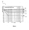
- FIG. 4 is a graph illustrating the directivity target functions for angle-dependent attenuation.
- FIG. 5 is a graph illustrating the measurement of the amplitude frequency response of one mounted tweeter at various vertical out-of-axis displacement angles.
- FIG. 6 is a graph illustrating acceptable obtained results for a line array similar to the one illustrated in FIG. 1 , determined along the y-axis.
- Fig. 7 is a graph illustrating the frequency response of the digital filters assigned to signal paths of the line array design illustrated in FIG. 1 after a cost minimization function has been applied.
- FIG. 8 is a graph illustrating a smoothed frequency response of the third signal path illustrated i n FIG. 7 together with the frequency response of the linear FIR filter after the FIR filter coefficient has been established and applied.
- Fig. 1 illustrates an example implementation of a one-dimensional (1D) multi-way loudspeaker 100 of the invention and a block diagram of the signal flow to each of the loudspeaker drivers in the system 100.
- the multi-way loudspeaker 100 may be designed as a six-way loudspeaker having (i) a center tweeter 102 connected to a first power D/A converter 103, (ii) two additional tweeters 104 and 106 connected to a second power D/A converter 105, (iii) two midrange drivers 108 and 110 connected to a third power D/A converter 107, (iv) two midrange drivers 112 and 114 connected to fourth power D/A converter 109, (v) two woofers 116 and 118 connected to a fifth power D/A converter 111 and (vi) four woofers 120, 122, 124 and 126 connected to a sixth power D/A converter 113.
- the connection between the loudspeakers to each amplifier represents a different way
- the drivers also referred to as transducers, may be mounted in a housing 154 comprised of separate sealed compartments 128, 130, 132, 134, 140, 142 and 148, as indicated by separators 136, 138, 144, 146, 150 and 152.
- a housing 154 comprised of separate sealed compartments 128, 130, 132, 134, 140, 142 and 148, as indicated by separators 136, 138, 144, 146, 150 and 152.
- the loudspeaker system may be designed such that the compartments are not visible to the consumer when embodied in a finished product.
- Compartment 128, containing woofers 120, 122 may be separated by separator 136 from compartment 132, which contains woofer 116.
- compartment 130 which contains woofers 126 and 124, may be separated by separator 138 from compartment 134, which contains woofer 118.
- the midrange drivers 112 and 114 contained in compartments 140 and 142, respectively, may be separated from compartments 132 and 134 by separators 144 and 146, respectively. All of the tweeters 102, 104, 106, and midrange drivers 110 and 108 may also b e contained in compartment 148 and separated from compartments 140 and 142 by separators 150 and 152, respectively.
- FIG. 1 illustrates the center tweeter 102, tweeters 104 and 106, midrange drivers 110, 108, 112, 114, 116 and 118 and low-frequency woofers 120, 122, 124 and 126 mounted linearly along the y-axis and symmetrically about the center tweeter 102.
- a typical arrangement may include tweeters 102, 104 and 106 of outer diameters of approximately 40mm, midrange drivers 110, 108, 112, 114, 116 and 118 of outer diameters of approximately 80mm, and woofers 120, 122, 124 and 126 of outer diameters of approximately 120mm.
- transducer cone size may differ based on the desired application and desired size of the array.
- the transducers m ay utilize neodymium magnets, although it is not necessary for the described application to utilize that particular type of magnet.
- the center tweeter 102 may be mounted on the y-axis at the center point 0 at the intersection between the x and y axis.
- the tweeters 104 and 106 may be mounted at their centers approximately +/- 40 mm from the center point.
- the midrange drivers 110 and 108 may then be mounted at their centers approximately +/- 110mm from the center point 0.
- the midrange drivers 112 and 114 may then be mounted at their centers approximately +/-220mm from the center point.
- the low-frequency woofers 116 and 118 may t hen b mounted at their c enters approximately + /-350mm from the center point.
- the low frequency woofers 120 and 124 may then be mounted at their centers approximately +/-520 mm from the center point.
- the low frequency woofers 122 and 126 may then be mounted at their centers approximately +/- 860mm from the center point.
- FIG. 1 also illustrates a block diagram 160 of the signal flow of the multi-way loudspeaker system. While FIG. 1 illustrates six ways 162, 164, 166, 168, 170 and 172 of signal flow, a channel may be divided into two or more ways.
- the signal flow comprises a digital input 174 that may be implemented using standard interface formats, such as SPDIF or IEEE1394 and their derivatives, and that can be connected to the drivers through various paths or ways, such as those illustrated in FIG. 1 .
- Each path or way 162, 164, 166, 168, 170 and 172 may contain a digital FIR filter 176 and a power D/A converter 103, 105, 107, 109, 111 and 113 connected to either a single or to multiple loudspeaker drivers.
- the power D/A converters 103, 105, 107, 109, 111 and 113 may be realized as cascades of conventional audio D/A converters (not shown) and power amplifiers (not shown), or as class-D power amplifiers (not shown) with direct digital inputs.
- the FIR filters 176 may be implemented with a digital signal processor (DSP) (not shown).
- the loudspeaker drivers may be tweeters, midrange drivers or woofers, such as those illustrated.
- each multiple FIR filter 176 are connected to multiple power D/A converters 103, 105, 107, 109, 111 and 113, that are then fed to multiple loudspeaker drivers 102, 104, 106, 108, 110, 112, 114, 116, 118, 120, 122, 124, and 126 that are mounted on a baffle of the housing 154. More than one driver such as 120, 122, 124, and 126 may be connected in parallel to a path or way 162 containing a power D/A converter 113.
- FIG. 2 is another one-dimensional multi-way loudspeaker, similar to the loudspeaker of FIG. 1 , except that it contains two rather than four mid-range drivers and four rather than six woofers.
- FIG. 2 illustrates a single channel, onedimensional, four-way loudspeaker 200 having a center tweeter 202 encircled by two additional tweeters 204 and 206. Additionally, the loudspeaker 200 contains two midrange drivers 208 and 210 and four woofers 214, 216, 218 and 220.
- Tweeters 202, 204 and 206, the midrange drivers 208 and 210, and the four woofers 214, 216, 218 and 220 are all aligned linearly along the y-axis symmetrically about the center tweeter 202.
- a first path may be fed to center tweeter 202; a second path may be fed to tweeters 204 and 206; and a third path may be fed to midrange drivers 208 and 210.
- Woofers 214, 218, 216 and 220 may all be fed by a fourth path.
- a typical arrangement of the multi-way loudspeaker illustrated in FIG, 2 may include tweeters 202, 204 and 206 of outer diameters of approximately 40mm, midrange drivers 208 and 210 of outer diameters of approximately 80mm, and woofers 214, 216, 218 and 220 of outer diameters of approximately 160mm.
- transducer cone size may differ based on the desired application and desired size of the array. The number of signal paths and number of any particular type of driver may also vary.
- the center tweeter 202 may be mounted on the y-axis at the center point 0, which is illustrated in FIG. 2 at the intersection between the x and y axis.
- the tweeters 204 and 206 may then be mounted at their centers approximately +/- 40 mm from the center point.
- the midrange drivers 208 and 210 may then be mounted at their centers approximately +/- 110 mm from the center point 0.
- the low frequency woofers 214 and 216 may then be mounted at their centers approximately +/-240mm from the center point.
- the low frequency woofers 218 and 220 may then be mounted at their centers approximately +/-380mm from the center point.
- FIG. 3 is a flow chart of a filter design algorithm 300 used to design the loudspeaker system of the invention.
- the purpose of the filter design algorithm 300 is to determine the coefficients for each FIR filter for each signal flow path of the loudspeaker.
- the initial driver positions and initial directivity target functions are first determined 310.
- the initial positions or design configuration of the speaker and drivers may be designed in accordance with a number of different variables, depending upon the application, such as the desired size of the speaker, intended application or use, manufacturing constraints, aesthetics or other product design aspects.
- Driver coordinates are then prescribed for each driver along the main axis.
- Initial guesses for directivity target functions are then set, which includes establishing frequency points on a logarithmic scale within an interval of interest.
- step 314 the position of the drivers are then modified and the cost minimization function is applied again 316. This cycle may be repeated until the results meet the requirements. Once the results meet the requirements, the linear phase filter coefficients are computed 318. Additionally computations 320 may also be made to equalize the drivers and to compensate for phase shifts and to modify beam steering.
- initial driver positions and initial directivity target functions are established.
- the number, position, size and orientation of the drivers are primarily determined by product design aspects.
- p(n) [-.86, -.52, -.35, -.22, -.11, -.04, 0, .04, .11, .22, .35, .52, .86]m (meters).
- FIG. 4 is a graph illustrating an example set of target functions for angle-dependent attenuation at five specific angles q.
- the directivity target functions specify the intended sound level attenuation in dB (y-axis) that can be measured at various frequencies at sufficiently large distance from the speaker (larger than the dimensions of the speaker) in an anechoic environment, at an angle q degrees apart from a line perpendicular to the origin (center tweeter).
- Frequency vector f specifies a set of frequency points, e.g. 100, on a logarithmic scale within the interval of interest, e.g. 100Hz...20kHz.
- the on-axis target function 402 remains constant at 0db across the entire frequency range.
- the target directivity functions at ten (10) degrees 404, twenty (20) degrees 410, thirty (30) degrees 412 and forty (40) degrees 414, all begin at T 0dB and descend on a double logarithmic scale until the functions reach fc , which is represented by 350Hz in FIG, 4 , and then remain constant across the remaining frequency range of interest.
- FIG. 5 illustrates the measured frequency responses 500 of one mounted tweeter at various vertical displacement angles normalized to on axis.
- line 502 represents the on-axis response
- line 504 is the measured frequency response at ten degrees
- line 506 is the response at twenty degrees
- line 508 is the response at thirty degrees
- line 510 is the measured frequency response at forty degrees, all measured at frequencies ranging between 1 kHz and 20 kHz
- the minimization is performed by varying real-valued frequency points of the channel filters Copt(n,f), where n is the driver index and f is frequency, within the interval [0,1].
- the above described procedure for minimizing the cost function may be performed by a function "fminsearch,” that is part of the Matlab® software package, owned and distributed by The MathWorks, Inc.
- the "fminsearch" function in the Matlab software packages uses the Nelder-Mead simplex algorithm or their derivatives. Alternatively, an exhaustive search over a predefined grid on the constrained parameter range may be applied. Other methodologies may also be used to minimize the cost function.
- FIG. 6 is a graph 600 of acceptable obtained results for a line array similar to the one illustrated in FIG. 1 , determined along the y-axis.
- the graph shows the obtained filter frequency responses V(f,q) after passing step 314 in Fig.
- line 602 represents the on-axis response V(f,q(1))
- line 604 the frequency response at ten degrees V(f,q(2))
- line 606 is the response at twenty degrees V(f,q(3))
- line 608 is the response at thirty degrees V(f,q(4))
- line 610 is the measured frequency response at forty degrees V(f,q(5)), all shown at frequencies ranging between 50 Hz and 20 kHz.
- Fig. 7 is graph 700 illustrating the resulting frequency responses Copt(n,f) of each of the six signal paths in the line array loudspeakers system illustrated in FIG. 1 once the cost minimization function has been applied and the obtained results have been found to be sufficiently small or within the acceptable range for the desired application.
- the line represented by L1 or 702 is the frequency response of the first signal path which feeds the center channel tweeter 102 ( FIG. 1 );
- L2 or 704 is the frequency response of the second signal path which feeds the tweeters 104 and 106 ( FIG. 1 );
- L3 or 706 is the frequency response of the third signal path which feeds the mid-range drivers 110 and 108 ( FIG.
- L4 or 708 is the frequency response of the forth signal path which feeds mid-range drivers 114 and 116 ( FIG. 1 );
- L5 or 710 is the frequency response of the fifth signal path which feeds woofers 116 and 118 and
- L6 or 812 is the frequency response of the sixth signal path which feeds woofers 120, 122, 124 and 126.
- the driver positions or geometry, and/or parameters q (i) and fc of the target function T (f,g) should then be modified. Once modified, the cost minimization function should again be applied and the process should be repeated until obtained results and the target are sufficiently small or with an acceptable range for the application.
- One method for determining the FIR coefficients is to use a Fourier approximation (frequency sampling method), to obtain linear phase filters of given degree.
- a degree should be chosen such that the approximation becomes sufficiently accurate.
- the Fourier approximation method may be performed by a function "firls,” that is part of the Matlab® software package, owned and distributed by The MathWorks, Inc. Similar methodologies may be used to minimize the cost function by implementing in other software systems.
- Fig. 8 is a graph 800 illustrating a frequency response of one signal path 802 which is identical to L 4 or 708 of Fig. 7 , together with the frequency response of the linear phase FIR filter 804 after the FIR filter coefficients have been obtained in accordance with the method described above.
- FIR filters can be made to equalize the measured frequency response of one or more drivers (in particular tweeters, midranges).
- the impulse response of such a filter can be obtained by well-known methods, and must be convolved with the impulse response of the linear phase channel filter when determining the FIR filter coefficients, as described above.
- the voice coils acoustic centers of the drivers
- appropriate delays can be incorporated into the filters by adding leading zeros to the FIR impulse response.
- the geometry of the one-dimensional layout may be modified such that the design process can be carried out in two dimensions, i.e., along both the x and y-axis, as described above by making the geometry symmetrical. Due to the symmetry, the same directivity characteristics will result along the y-axis (vertical), except of a higher corner frequency.
Landscapes
- Health & Medical Sciences (AREA)
- Otolaryngology (AREA)
- Physics & Mathematics (AREA)
- Engineering & Computer Science (AREA)
- Acoustics & Sound (AREA)
- Signal Processing (AREA)
- General Health & Medical Sciences (AREA)
- Neurosurgery (AREA)
- Circuit For Audible Band Transducer (AREA)
- Obtaining Desirable Characteristics In Audible-Bandwidth Transducers (AREA)
- Stereophonic Arrangements (AREA)
- Diaphragms For Electromechanical Transducers (AREA)
- Audible-Bandwidth Dynamoelectric Transducers Other Than Pickups (AREA)
Abstract
Description
- This invention generally relates to a multi-way loudspeaker system and in particular to a multi-way loudspeaker system comprised of an array of multiple drivers capable of achieving high-quality sound.
- High-quality loudspeakers for the audio frequency ranges generally employ multiple specialized drivers for dedicated parts of the audio frequency band, such as tweeters (generally 2kHz-20kHz); midrange drivers (generally 200Hz-5kHz) and woofers (generally 20Hz-1kHz). Because of the necessary spacing due to the physical size of the specialized drivers, which is comparable with the wavelength of the radiated sound, the acoustic outputs of the drivers sum up to the intended flat, frequency-independent response only on a single line perpendicular to the loudspeaker, usually at the so-called acoustic center. Outside of that axis, frequency responses are more or less distorted due to interferences caused by different path lengths of sound waves traveling from the drivers to the considered points in space. There have been many attempts in history to build loudspeakers with a controlled sound field over a larger space with smooth out-of-axis.responses.
- The international patent application
WO 03/034780 A2 - For example, D'Appolito has presented a geometric approach to eliminate lobing errors in multi-way loudspeakers - a configuration using a center tweeter and two woofers arranged symmetrically along a vertical axis. Several loudspeaker manufacturers have adopted that approach and have even expanded upon it by using arrays of symmetrically arranged midrange drivers and woofers around one or two center tweeters. D'Appolito designs and those of the manufacturers that have adopted D'Appolito's approach utilize passive or analog crossover circuits or digital filters that emulate analog filters in a digital domain. Analog or passive crossover circuits inevitably introduce phase distortion. Further, with this design, spacing is not optimum and in general too large to completely avoid out-of-axis aberrations from an ideal smooth response.
- In an alternative solution, the basic design concept is to apply very steep, "brick-wall" finite impulse response (FIR) filters to avoid large transition bands, so that the errors become inaudible. However, the individual polar responses of the involved drivers may still be different at the transition point, leaving audible discontinuities. Thus, with this design solution, it may be difficult to achieve a prescribed, smooth polar behavior throughout the whole audible range.
- In yet another alternative, Van der Wal suggests that logarithmically spaced transducer arrays can achieve a very well controlled directivity, approximately constant over a wide frequency range, in one dimension. Some embodiments of this technique are described in
U.S. Patent No. 6,128,395 . Like the previously described techniques, this design technique is limited because (i) the logarithmic spacing is prescribed only according to a given formula; (ii) the filter design is only valid for a particular case and (iii) severe errors may occur if the actual spacing deviates from logarithmic spacing, which may be unavoidable due to physical dimensions of the drivers or due to design constraints. Further, the design is restricted to one type of drivers, i.e., full-range drivers, limiting the application to public address systems. Thus, a need still exists for a loudspeaker configuration and filter design that overcomes the limitations of the prior art by providing a loudspeaker system that can contain drivers of various physical dimensions and can achieve prescribed, constant directivity over a large area in both the vertical and horizontal planes. - The invention is a a method for designing a line array loudspeaker speaker system according to
claim 1. - In one embodiment, the line array includes a plurality of tweeters, mid-range drivers and woofers that are arranged in a single housing or assembled as a single unit, having sealed compartments that separate certain drivers from one another to prevent coupling of the drivers. The line array may be a s ingle channel array having various signal paths from the input to individual loudspeaker drivers or to a plurality of drivers. Each signal path comprises digital input and contains a digital FIR filter and a power D/A converter connected to either a single driver or to multiple drivers.
- The performance, positioning and arrangement of the loudspeaker drivers in the line array are determined by a filter design algorithm that establishes the coefficients for each FIR filter in each signal flow path of the loudspeaker. A cost minimization function is applied to prescribed frequency points, using initial driver positions and initial directivity target functions, which e stablish frequency points on a logarithmic scale within the frequency range of interest. If the obtained results from the application of the cost minimization function do not meet the performance requirements of the system, the position of the drivers may then be modified and the cost minimization function may be reapplied until the obtained results meet the system requirements. Once the obtained results meet the system requirements, the linear phase filter coefficients for each FIR filter in a signal path are computed using the Fourier approximation method or other frequency sampling method.
- The multi-way loudspeakers may include built-in DSP processing, D/A converters and amplifiers and may be connected to a digital network (e.g. IEEE 1394 standard). Further, the multi-way loudspeaker system of the invention, due to its compact dimensions, may be designed as a wall-mountable surround system.
- The multi-way loudspeaker system may employ drivers of different sizes, producing low distortion, high-power handling because specialized drivers can operate optimal in their dedicated frequency band, as opposed to arrays of identical wide-band drivers. The multi-way speaker design of the invention can also provide better control of in-room responses due to smooth out-of-axis responses. The system is further able to control the frequency response of reflected sound, as well as the total sound power, thereby suppressing floor and ceiling reflections.
- Other, methods, features and advantages of the invention will be or will become apparent to one with skill in the art upon examination of the following figures and detailed description. It is intended that all such additional systems, methods, features and advantages be included within this description, be within the scope of the invention, and be protected by the accompanying claims.
- The invention can be better understood with reference to the following figures. The components in the figures are not necessarily to scale, emphasis instead being placed upon illustrating the principles of the invention. Moreover, in the figures, like reference numerals designate corresponding parts throughout the different views.
-
FIG. 1 illustrates an example of a one-dimensional six-way loudspeaker system mounted along the y-axis symmetrically to origin and a block diagram of signal flow to each of the loudspeaker drivers in the system. -
FIG. 2 illustrates another example implementation of a one-dimensional (1D) four-way loudspeaker system using nine loudspeaker drivers mounted along the y-axis symmetrically to origin. -
FIG. 3 is a flow chart of a filter design algorithm used to design the loudspeaker system. -
FIG. 4 is a graph illustrating the directivity target functions for angle-dependent attenuation. -
FIG. 5 is a graph illustrating the measurement of the amplitude frequency response of one mounted tweeter at various vertical out-of-axis displacement angles. -
FIG. 6 is a graph illustrating acceptable obtained results for a line array similar to the one illustrated inFIG. 1 , determined along the y-axis. -
Fig. 7 is a graph illustrating the frequency response of the digital filters assigned to signal paths of the line array design illustrated inFIG. 1 after a cost minimization function has been applied. -
FIG. 8 is a graph illustrating a smoothed frequency response of the third signal path illustrated i nFIG. 7 together with the frequency response of the linear FIR filter after the FIR filter coefficient has been established and applied. -
Fig. 1 illustrates an example implementation of a one-dimensional (1D)multi-way loudspeaker 100 of the invention and a block diagram of the signal flow to each of the loudspeaker drivers in thesystem 100. As shown inFIG. 1 , themulti-way loudspeaker 100 may be designed as a six-way loudspeaker having (i) acenter tweeter 102 connected to a first power D/A converter 103, (ii) twoadditional tweeters 104 and 106 connected to a second power D/A converter 105, (iii) twomidrange drivers A converter 107, (iv) twomidrange drivers A converter 109, (v) twowoofers A converter 111 and (vi) fourwoofers A converter 113. The connection between the loudspeakers to each amplifier represents a different way in the multi-way loudspeaker. Thus, the loudspeaker may be designed as a single-channel multi-way loudspeaker. - In
FIG. 1 , the drivers, also referred to as transducers, may be mounted in a housing 154 comprised of separate sealedcompartments separators FIG. 1 , the loudspeaker system may be designed such that the compartments are not visible to the consumer when embodied in a finished product.Compartment 128, containingwoofers separator 136 fromcompartment 132, which containswoofer 116. Similarly,compartment 130, which containswoofers separator 138 fromcompartment 134, which containswoofer 118. Themidrange drivers compartments compartments separators tweeters midrange drivers compartment 148 and separated fromcompartments separators -
FIG. 1 illustrates thecenter tweeter 102,tweeters 104 and 106,midrange drivers frequency woofers center tweeter 102. A typical arrangement may includetweeters midrange drivers woofers - The
center tweeter 102 may be mounted on the y-axis at thecenter point 0 at the intersection between the x and y axis. Thetweeters 104 and 106 may be mounted at their centers approximately +/- 40 mm from the center point. Themidrange drivers center point 0. Themidrange drivers frequency woofers low frequency woofers low frequency woofers -
FIG. 1 also illustrates a block diagram 160 of the signal flow of the multi-way loudspeaker system. WhileFIG. 1 illustrates sixways FIG. 1 . Each path orway digital FIR filter 176 and a power D/A converter A converters - In operation, the outputs of each
multiple FIR filter 176 are connected to multiple power D/A converters multiple loudspeaker drivers way 162 containing a power D/A converter 113. -
FIG. 2 is another one-dimensional multi-way loudspeaker, similar to the loudspeaker ofFIG. 1 , except that it contains two rather than four mid-range drivers and four rather than six woofers. In particular,FIG. 2 illustrates a single channel, onedimensional, four-way loudspeaker 200 having acenter tweeter 202 encircled by twoadditional tweeters 204 and 206. Additionally, theloudspeaker 200 contains twomidrange drivers woofers Tweeters midrange drivers woofers center tweeter 202. - Three signal paths (not shown) may be fed into
compartment 226. A first path may be fed tocenter tweeter 202; a second path may be fed totweeters 204 and 206; and a third path may be fed tomidrange drivers compartment 226, divided by separators represented bylines compartments woofers woofers Woofers - A typical arrangement of the multi-way loudspeaker illustrated in
FIG, 2 may includetweeters midrange drivers woofers - The
center tweeter 202 may be mounted on the y-axis at thecenter point 0, which is illustrated inFIG. 2 at the intersection between the x and y axis. Thetweeters 204 and 206 may then be mounted at their centers approximately +/- 40 mm from the center point. - The
midrange drivers center point 0. Thelow frequency woofers low frequency woofers -
FIG. 3 is a flow chart of afilter design algorithm 300 used to design the loudspeaker system of the invention. The purpose of thefilter design algorithm 300 is to determine the coefficients for each FIR filter for each signal flow path of the loudspeaker. As illustrated in further detail below, the initial driver positions and initial directivity target functions are first determined 310. The initial positions or design configuration of the speaker and drivers may be designed in accordance with a number of different variables, depending upon the application, such as the desired size of the speaker, intended application or use, manufacturing constraints, aesthetics or other product design aspects. Driver coordinates are then prescribed for each driver along the main axis. Initial guesses for directivity target functions are then set, which includes establishing frequency points on a logarithmic scale within an interval of interest. The cost function is then minimized at the prescribed frequency points 312. If the results do not meet the performance requirements of the system,step 314, the position of the drivers are then modified and the cost minimization function is applied again 316. This cycle may be repeated until the results meet the requirements. Once the results meet the requirements, the linear phase filter coefficients are computed 318. Additionallycomputations 320 may also be made to equalize the drivers and to compensate for phase shifts and to modify beam steering. - In the
first step 310, the initial driver positions and initial directivity target functions are established. As previously mentioned, the number, position, size and orientation of the drivers are primarily determined by product design aspects. Once orientated, initial coordinate values may then be prescribed for initial driver coordinates p(n), n = 1..N for N drivers on the main axis. For example, in a one-dimensional (1D) array as illustrated inFIG. 1 , N=13: p(n) =[-.86, -.52, -.35, -.22, -.11, -.04, 0, .04, .11, .22, .35, .52, .86]m (meters). - To determine the initial directivity target functions, one must define initial guesses for directivity target functions T(f,q), which are determined based upon the desired performance of the drivers at specific angles q.
FIG. 4 is a graph illustrating an example set of target functions for angle-dependent attenuation at five specific angles q. The directivity target functions specify the intended sound level attenuation in dB (y-axis) that can be measured at various frequencies at sufficiently large distance from the speaker (larger than the dimensions of the speaker) in an anechoic environment, at an angle q degrees apart from a line perpendicular to the origin (center tweeter). Frequency vector f specifies a set of frequency points, e.g. 100, on a logarithmic scale within the interval of interest, e.g. 100Hz...20kHz. - Angle vector q(i),i=1,..,Nq specifies a set of angles for which the optimization will be performed. While
FIG. 4 , illustrates the initial guess for directivity at five set angles:
- Except for the on-axis target function, the target functions at each angle, are linearly descending on a double logarithmic scale from T=0dB at f=0 until a value T<0dB at a specified frequency fc (e.g. fc=350Hz), then remain constant. The on-
axis target function 402 remains constant at 0db across the entire frequency range. The target directivity functions at ten (10)degrees 404, twenty (20)degrees 410, thirty (30)degrees 412 and forty (40)degrees 414, all begin at T=0dB and descend on a double logarithmic scale until the functions reach fc , which is represented by 350Hz inFIG, 4 , and then remain constant across the remaining frequency range of interest. - After the initial driver positions and initial directivity target functions are determined, the
next step 312 is to minimize the cost function F(f) at the prescribed frequency vector points f, starting with the lowest frequency increment stepwise, e.g. 100 Hz, using the obtained solution as the initial solution for the next step, respectively, by using the following equations:


FIG. 5. FIG. 5 illustrates the measuredfrequency responses 500 of one mounted tweeter at various vertical displacement angles normalized to on axis. InFIG. 5 ,line 502 represents the on-axis response,line 504 is the measured frequency response at ten degrees,line 506 is the response at twenty degrees,line 508 is the response at thirty degrees and line 510 is the measured frequency response at forty degrees, all measured at frequencies ranging between 1 kHz and 20 kHz, - Further, the minimization is performed by varying real-valued frequency points of the channel filters Copt(n,f), where n is the driver index and f is frequency, within the interval [0,1]. In addition, the constraint

- The above described procedure for minimizing the cost function may be performed by a function "fminsearch," that is part of the Matlab® software package, owned and distributed by The MathWorks, Inc. The "fminsearch" function in the Matlab software packages uses the Nelder-Mead simplex algorithm or their derivatives. Alternatively, an exhaustive search over a predefined grid on the constrained parameter range may be applied. Other methodologies may also be used to minimize the cost function.
- If the deviation between the obtained result and the target is sufficiently small, or acceptable as determined by one skilled in the art for the particular design application, the FIR filter coefficients for each signal path in the line array are then obtained.
FIG. 6 is a graph 600 of acceptable obtained results for a line array similar to the one illustrated inFIG. 1 , determined along the y-axis. The graph shows the obtained filter frequency responses V(f,q) after passingstep 314 inFig. 3 , Passing means that the result met the requirements, InFIG, 6 ,line 602 represents the on-axis response V(f,q(1)),line 604 the frequency response at ten degrees V(f,q(2)), line 606 is the response at twenty degrees V(f,q(3)), line 608 is the response at thirty degrees V(f,q(4)) andline 610 is the measured frequency response at forty degrees V(f,q(5)), all shown at frequencies ranging between 50 Hz and 20 kHz. -
Fig. 7 isgraph 700 illustrating the resulting frequency responses Copt(n,f) of each of the six signal paths in the line array loudspeakers system illustrated inFIG. 1 once the cost minimization function has been applied and the obtained results have been found to be sufficiently small or within the acceptable range for the desired application. The line represented by L1 or 702 is the frequency response of the first signal path which feeds the center channel tweeter 102 (FIG. 1 ); L2 or 704 is the frequency response of the second signal path which feeds thetweeters 104 and 106 (FIG. 1 ); L3 or 706 is the frequency response of the third signal path which feeds themid-range drivers 110 and 108 (FIG. 1 ); L4 or 708 is the frequency response of the forth signal path which feedsmid-range drivers 114 and 116 (FIG. 1 ); L5 or 710 is the frequency response of the fifth signal path which feedswoofers woofers - If the deviation between the obtained results and the target are not acceptable for the particular design application, i.e. or are too large, the driver positions or geometry, and/or parameters q (i) and fc of the target function T (f,g) (see
Fig. 3 ) should then be modified. Once modified, the cost minimization function should again be applied and the process should be repeated until obtained results and the target are sufficiently small or with an acceptable range for the application. - Once the driver positions and driver geometry are positioned such that the algorithm as shown in
Fig. 3 yields results within an acceptable range of the target function, the FIR filter coefficients for each signal path n=1..N must then be determined, depicted asstep 318 inFig. 3 . One method for determining the FIR coefficients is to use a Fourier approximation (frequency sampling method), to obtain linear phase filters of given degree. When applying the Fourier approximation, or other frequency sampling method, a degree should be chosen such that the approximation becomes sufficiently accurate. - The Fourier approximation method may be performed by a function "firls," that is part of the Matlab® software package, owned and distributed by The MathWorks, Inc. Similar methodologies may be used to minimize the cost function by implementing in other software systems.
-
Fig. 8 is a graph 800 illustrating a frequency response of onesignal path 802 which is identical toL Fig. 7 , together with the frequency response of the linearphase FIR filter 804 after the FIR filter coefficients have been obtained in accordance with the method described above. - Additionally, modifications can be made to the FIR filters to equalize the measured frequency response of one or more drivers (in particular tweeters, midranges). The impulse response of such a filter can be obtained by well-known methods, and must be convolved with the impulse response of the linear phase channel filter when determining the FIR filter coefficients, as described above. Further, the voice coils (acoustic centers of the drivers) may not be aligned. To compensate for this, appropriate delays can be incorporated into the filters by adding leading zeros to the FIR impulse response.
- Further, delays may be added to each channel in accordance with the following equation:

- Further, the geometry of the one-dimensional layout may be modified such that the design process can be carried out in two dimensions, i.e., along both the x and y-axis, as described above by making the geometry symmetrical. Due to the symmetry, the same directivity characteristics will result along the y-axis (vertical), except of a higher corner frequency.
- While various embodiments of the invention have been described, it will be apparent to those of ordinary skill in the art that many more embodiments and implementations are possible within the scope of this invention. Accordingly, the invention is not to be restricted except in light of the attached claims and their equivalents.
Claims (4)
- A method for designing a line array loudspeaker (100, 200), comprising the steps of:establishing initial positions of drivers (102, 104, 106, 108, 110, 112, 114, 116, 118, 120, 122, 124, 126; 202, 204, 206, 208, 210, 214, 216, 218, 220) comprising one center driver (102, 202) mounted in the center of a longitudinal section of the loudspeaker (100, 200) and at least two drivers (104, 106, 204, 206) of a size different than the center driver (102, 202) mounted symmetrically about the center driver, wherein the center driver (102, 202) and the two drivers (104, 106, 204, 206) mounted symmetrically about the center driver each is configured to receive an analog output signal from at least one power D/A converter (103, 105, 107, 109, 111, 113) configured to receive a digital signal having been filtered through at least one digital FIR filter (176);characterized by
establishing initial directivity target functions for the loudspeaker (100, 200) based upon the desired performance of the drivers at specific angles;
establishing frequency points on a logarithmic scale within a predetermined frequency range based upon the established initial directivity target functions; and
applying a cost minimization function at the frequency points, starting with the lowest frequency increment stepwise. - The method of claim 1, where the initial driver positions are coordinates relative to the center of the loudspeaker (100, 200).
- The method of claim 1, further comprising the step of verifying the results obtained from the cost minimization function against the desired performance standards.
- The method of claim 1, where the Fourier approximation method is utilized to establish the linear phase filter coefficients.
Applications Claiming Priority (2)
| Application Number | Priority Date | Filing Date | Title |
|---|---|---|---|
| US10/771,190 US8170233B2 (en) | 2004-02-02 | 2004-02-02 | Loudspeaker array system |
| US771190 | 2004-02-02 |
Publications (2)
| Publication Number | Publication Date |
|---|---|
| EP1560460A1 EP1560460A1 (en) | 2005-08-03 |
| EP1560460B1 true EP1560460B1 (en) | 2010-02-24 |
Family
ID=34654407
Family Applications (1)
| Application Number | Title | Priority Date | Filing Date |
|---|---|---|---|
| EP04028748A Expired - Lifetime EP1560460B1 (en) | 2004-02-02 | 2004-12-03 | Linear array loudspeaker and method for positioning of transducers |
Country Status (5)
| Country | Link |
|---|---|
| US (4) | US8170233B2 (en) |
| EP (1) | EP1560460B1 (en) |
| JP (2) | JP4171468B2 (en) |
| AT (1) | ATE459212T1 (en) |
| DE (1) | DE602004025666D1 (en) |
Families Citing this family (50)
| Publication number | Priority date | Publication date | Assignee | Title |
|---|---|---|---|---|
| US8170233B2 (en) * | 2004-02-02 | 2012-05-01 | Harman International Industries, Incorporated | Loudspeaker array system |
| GB0514361D0 (en) * | 2005-07-12 | 2005-08-17 | 1 Ltd | Compact surround sound effects system |
| US8351616B1 (en) | 2005-11-23 | 2013-01-08 | Graber Curtis E | Array of multiple LF transducers with ultrahigh cardioid sound pattern generation |
| JP4625756B2 (en) * | 2005-12-02 | 2011-02-02 | ハーマン インターナショナル インダストリーズ インコーポレイテッド | Loudspeaker array system |
| US20070201711A1 (en) * | 2005-12-16 | 2007-08-30 | Meyer John D | Loudspeaker system and method for producing a controllable synthesized sound field |
| EP1802163A1 (en) * | 2005-12-20 | 2007-06-27 | Harman International Industries, Incorporated | Loudspeaker array system |
| US7672472B2 (en) * | 2006-01-03 | 2010-03-02 | Iroquois Holding Co. | Audio transducer |
| US8094868B2 (en) * | 2006-01-03 | 2012-01-10 | Oxford J Craig | Non-directional transducer |
| JP2009524963A (en) * | 2006-01-27 | 2009-07-02 | コーニンクレッカ フィリップス エレクトロニクス エヌ ヴィ | Sound reproduction |
| US7624839B1 (en) * | 2006-05-12 | 2009-12-01 | Graber Curtis E | Enclosure for symbiotic active/passive operation of an acoustic driver |
| FR2901448B1 (en) * | 2006-05-19 | 2009-01-09 | Cabasse Sa | DEVICE AND METHOD FOR FILTERING AN ACTIVATION SIGNAL FOR POWERING A COAXIAL MEMBRANE SPEAKER, ACOUSTICAL ENCLOSURE, CORRESPONDING COMPUTER PROGRAMM AND MEANS FOR STORAGE. |
| US20080044050A1 (en) * | 2006-08-16 | 2008-02-21 | Gpx, Inc. | Multi-Channel Speaker System |
| TWI477158B (en) | 2006-10-16 | 2015-03-11 | Thx Ltd | Speaker line array configuration and related sound processing |
| US8238588B2 (en) * | 2006-12-18 | 2012-08-07 | Meyer Sound Laboratories, Incorporated | Loudspeaker system and method for producing synthesized directional sound beam |
| KR101297300B1 (en) * | 2007-01-31 | 2013-08-16 | 삼성전자주식회사 | Front Surround system and method for processing signal using speaker array |
| JP4863287B2 (en) * | 2007-03-29 | 2012-01-25 | 国立大学法人金沢大学 | Speaker array and speaker array system |
| EP2056627A1 (en) * | 2007-10-30 | 2009-05-06 | SonicEmotion AG | Method and device for improved sound field rendering accuracy within a preferred listening area |
| KR101572283B1 (en) * | 2007-11-21 | 2015-11-26 | 오디오 픽셀즈 리미티드 | Digital speaker apparatus |
| KR100919642B1 (en) * | 2007-12-17 | 2009-09-30 | 한국전자통신연구원 | Directive Speaker and mobile station thereof |
| US8379891B2 (en) * | 2008-06-04 | 2013-02-19 | Microsoft Corporation | Loudspeaker array design |
| EP2308244B1 (en) * | 2008-07-28 | 2012-05-30 | Koninklijke Philips Electronics N.V. | Audio system and method of operation therefor |
| KR101298487B1 (en) * | 2008-12-10 | 2013-08-22 | 삼성전자주식회사 | Directional sound generating apparatus and method |
| US20100246880A1 (en) * | 2009-03-30 | 2010-09-30 | Oxford J Craig | Method and apparatus for enhanced stimulation of the limbic auditory response |
| US8189822B2 (en) * | 2009-06-18 | 2012-05-29 | Robert Bosch Gmbh | Modular, line-array loudspeaker |
| DK2768241T3 (en) | 2010-03-11 | 2022-05-23 | Audio Pixels Ltd | ELECTROSTATIC, PARALLEL SHEET ACTUATORS, WHEN MOVABLE ELEMENTS ARE DRIVEN ONLY BY ELECTROSTATIC POWER, AND APPLICABLE PROCEDURES |
| US9788103B2 (en) * | 2010-09-03 | 2017-10-10 | Cirrus Logic International Semiconductor Ltd. | Speaker system which comprises speaker driver groups |
| JP5682244B2 (en) * | 2010-11-09 | 2015-03-11 | ソニー株式会社 | Speaker system |
| KR101785379B1 (en) | 2010-12-31 | 2017-10-16 | 삼성전자주식회사 | Method and apparatus for controlling distribution of spatial sound energy |
| US20120250912A1 (en) * | 2011-03-04 | 2012-10-04 | Wan Jin Chung | Line speaker system and layout |
| EP2856770B1 (en) | 2012-05-25 | 2018-07-04 | Audio Pixels Ltd. | A system, a method and a computer program product for controlling a set of actuator elements |
| WO2013175476A1 (en) | 2012-05-25 | 2013-11-28 | Audio Pixels Ltd. | A system, a method and a computer program product for controlling a group of actuator arrays for producing a physical effect |
| US9119012B2 (en) | 2012-06-28 | 2015-08-25 | Broadcom Corporation | Loudspeaker beamforming for personal audio focal points |
| KR101676634B1 (en) * | 2012-08-31 | 2016-11-16 | 돌비 레버러토리즈 라이쎈싱 코오포레이션 | Reflected sound rendering for object-based audio |
| US9743201B1 (en) * | 2013-03-14 | 2017-08-22 | Apple Inc. | Loudspeaker array protection management |
| WO2015117616A1 (en) | 2014-02-06 | 2015-08-13 | Bang & Olufsen A/S | Loudspeaker transducer arrangement for directivity control |
| DE102015203600B4 (en) * | 2014-08-22 | 2021-10-21 | Fraunhofer-Gesellschaft zur Förderung der angewandten Forschung e.V. | FIR filter coefficient calculation for beamforming filters |
| EP3195614A1 (en) * | 2014-09-19 | 2017-07-26 | Dolby Laboratories Licensing Corp. | Loudspeaker with narrow dispersion |
| CN104703088A (en) * | 2014-12-15 | 2015-06-10 | 浙江大丰实业股份有限公司 | Unified allocation method of distributed stage sound system |
| RU2612535C2 (en) | 2015-05-14 | 2017-03-09 | БОГУСЛАВСКИЙ Евгений | Loudspeaker |
| US10244317B2 (en) | 2015-09-22 | 2019-03-26 | Samsung Electronics Co., Ltd. | Beamforming array utilizing ring radiator loudspeakers and digital signal processing (DSP) optimization of a beamforming array |
| WO2017125789A1 (en) * | 2016-01-22 | 2017-07-27 | Glauk S.R.L. | Method and apparatus for playing audio by means of planar acoustic transducers |
| WO2018001490A1 (en) * | 2016-06-30 | 2018-01-04 | Huawei Technologies Co., Ltd. | Apparatus and method for generating a sound field |
| WO2018045133A1 (en) * | 2016-08-31 | 2018-03-08 | Harman International Industries, Incorporated | Variable acoustics loudspeaker |
| US10645516B2 (en) | 2016-08-31 | 2020-05-05 | Harman International Industries, Incorporated | Variable acoustic loudspeaker system and control |
| US10097917B2 (en) | 2016-10-20 | 2018-10-09 | Harman International Industries, Incorporated | System for reducing response anomalies in an acoustic pathway |
| US10805715B2 (en) * | 2017-05-17 | 2020-10-13 | Eric Jay Alexander | MTM loudspeaker using tweeter arrays |
| EP3425925A1 (en) * | 2017-07-07 | 2019-01-09 | Harman Becker Automotive Systems GmbH | Loudspeaker-room system |
| CN109905788B (en) * | 2019-03-27 | 2024-04-02 | 深圳市火乐科技发展有限公司 | Sound equipment |
| EP4021006A4 (en) * | 2019-08-23 | 2023-09-27 | Aniya, Setuo | SPEAKER DEVICE AND AUDIO APPARATUS |
| US20240056713A1 (en) * | 2022-08-12 | 2024-02-15 | Afco, Inc. | Speaker apparatus |
Family Cites Families (24)
| Publication number | Priority date | Publication date | Assignee | Title |
|---|---|---|---|---|
| US4311874A (en) * | 1979-12-17 | 1982-01-19 | Bell Telephone Laboratories, Incorporated | Teleconference microphone arrays |
| US4890689A (en) * | 1986-06-02 | 1990-01-02 | Tbh Productions, Inc. | Omnidirectional speaker system |
| US4885782A (en) * | 1987-05-29 | 1989-12-05 | Howard Krausse | Single and double symmetric loudspeaker driver configurations |
| JP2610991B2 (en) * | 1989-03-13 | 1997-05-14 | ティーオーエー株式会社 | Directivity control type speaker system |
| US4991221A (en) * | 1989-04-13 | 1991-02-05 | Rush James M | Active speaker system and components therefor |
| US5207214A (en) * | 1991-03-19 | 1993-05-04 | Romano Anthony J | Synthesizing array for three-dimensional sound field specification |
| JPH0541897A (en) * | 1991-08-07 | 1993-02-19 | Pioneer Electron Corp | Speaker equipment and directivity control method |
| JPH0638289A (en) | 1992-07-21 | 1994-02-10 | Matsushita Electric Ind Co Ltd | Directional speaker device |
| JPH07203581A (en) * | 1993-12-29 | 1995-08-04 | Matsushita Electric Ind Co Ltd | Directional speaker system |
| US5742690A (en) * | 1994-05-18 | 1998-04-21 | International Business Machine Corp. | Personal multimedia speaker system |
| NL9401860A (en) * | 1994-11-08 | 1996-06-03 | Duran Bv | Loudspeaker system with controlled directivity. |
| GB9506725D0 (en) * | 1995-03-31 | 1995-05-24 | Hooley Anthony | Improvements in or relating to loudspeakers |
| US5642429A (en) * | 1995-04-28 | 1997-06-24 | Janssen; Craig N. | Sound reproduction system having enhanced low frequency directional control characteristics |
| KR100414932B1 (en) | 1998-01-24 | 2004-04-03 | 삼성전자주식회사 | Method for communication data in cdma system |
| JP3422296B2 (en) * | 1999-08-30 | 2003-06-30 | ヤマハ株式会社 | Directional loudspeaker |
| JP3473517B2 (en) | 1999-09-24 | 2003-12-08 | ヤマハ株式会社 | Directional loudspeaker |
| JP2001186586A (en) | 1999-12-24 | 2001-07-06 | Mechanical Research:Kk | Audio equipment |
| JP2001231090A (en) * | 2000-02-18 | 2001-08-24 | Kenji Murata | Sub-woofer system |
| FR2828326A1 (en) | 2000-10-03 | 2003-02-07 | France Telecom | Teleconference hands free communication echo attenuation having multisensor/sound pick up and output signals complex weighting factors subjected maximising low frequency/near field constraints. |
| US7209566B2 (en) | 2001-09-25 | 2007-04-24 | Intel Corporation | Method and apparatus for determining a nonlinear response function for a loudspeaker |
| GB0124352D0 (en) | 2001-10-11 | 2001-11-28 | 1 Ltd | Signal processing device for acoustic transducer array |
| GB0304126D0 (en) | 2003-02-24 | 2003-03-26 | 1 Ltd | Sound beam loudspeaker system |
| US8170233B2 (en) * | 2004-02-02 | 2012-05-01 | Harman International Industries, Incorporated | Loudspeaker array system |
| US7260228B2 (en) * | 2004-03-10 | 2007-08-21 | Altec Lansing, A Division Of Plantronics, Inc. | Optimum driver spacing for a line array with a minimum number of radiating elements |
-
2004
- 2004-02-02 US US10/771,190 patent/US8170233B2/en not_active Expired - Fee Related
- 2004-09-08 US US10/935,929 patent/US8160268B2/en not_active Expired - Fee Related
- 2004-12-03 DE DE602004025666T patent/DE602004025666D1/en not_active Expired - Lifetime
- 2004-12-03 AT AT04028748T patent/ATE459212T1/en not_active IP Right Cessation
- 2004-12-03 EP EP04028748A patent/EP1560460B1/en not_active Expired - Lifetime
-
2005
- 2005-01-20 JP JP2005013412A patent/JP4171468B2/en not_active Expired - Fee Related
-
2007
- 2007-12-05 JP JP2007315278A patent/JP2008104229A/en active Pending
-
2012
- 2012-04-16 US US13/448,072 patent/US8781136B2/en not_active Expired - Fee Related
- 2012-04-30 US US13/460,450 patent/US9973862B2/en active Active
Also Published As
| Publication number | Publication date |
|---|---|
| EP1560460A1 (en) | 2005-08-03 |
| US8170233B2 (en) | 2012-05-01 |
| US20050169493A1 (en) | 2005-08-04 |
| JP2005218092A (en) | 2005-08-11 |
| US8781136B2 (en) | 2014-07-15 |
| US9973862B2 (en) | 2018-05-15 |
| US8160268B2 (en) | 2012-04-17 |
| JP4171468B2 (en) | 2008-10-22 |
| US20120283999A1 (en) | 2012-11-08 |
| ATE459212T1 (en) | 2010-03-15 |
| JP2008104229A (en) | 2008-05-01 |
| US20050180577A1 (en) | 2005-08-18 |
| US20120269368A1 (en) | 2012-10-25 |
| DE602004025666D1 (en) | 2010-04-08 |
Similar Documents
| Publication | Publication Date | Title |
|---|---|---|
| EP1560460B1 (en) | Linear array loudspeaker and method for positioning of transducers | |
| EP3737114B1 (en) | Speaker adjustment method and electronic device using the same | |
| US8401202B2 (en) | Speakers with a digital signal processor | |
| JP5788894B2 (en) | Method and audio system for processing a multi-channel audio signal for surround sound generation | |
| EP3425925A1 (en) | Loudspeaker-room system | |
| US10397692B2 (en) | Multi-driver array audio speaker system | |
| CN103503485B (en) | For generation of the method and apparatus of voice signal of three-dimensional effect with strengthening | |
| JP2023027133A (en) | Complementary sound output system and method | |
| CN1689371B (en) | Delay Network Microphone with Harmonic Networking | |
| US12170886B2 (en) | Methods and systems for optimizing behavior of audio playback systems | |
| US7991170B2 (en) | Loudspeaker crossover filter | |
| CN115706888A (en) | Method for designing a line array loudspeaker arrangement | |
| JP7678664B2 (en) | Loudspeaker system with active directional control | |
| JP4625756B2 (en) | Loudspeaker array system | |
| D’Appolito | Measuring Loudspeaker Low-Frequency Response | |
| EP1802163A1 (en) | Loudspeaker array system | |
| US12401964B2 (en) | Methods and systems for optimizing behavior of automotive audio playback systems | |
| WO2023284963A1 (en) | Audio device and method for producing a sound field using beamforming | |
| Wallace et al. | A low cost loudspeaker array for personal audio with enhanced vertical directivity | |
| Nilsson | Kardioidhögtalare: Jakten efter en väggmonterad högtalare med kardiodstrålning | |
| JP2010200349A (en) | Array system for loudspeaker | |
| Buddelmeyer | A Digital Loudspeaker Equalization Technique |
Legal Events
| Date | Code | Title | Description |
|---|---|---|---|
| PUAI | Public reference made under article 153(3) epc to a published international application that has entered the european phase |
Free format text: ORIGINAL CODE: 0009012 |
|
| AK | Designated contracting states |
Kind code of ref document: A1 Designated state(s): AT BE BG CH CY CZ DE DK EE ES FI FR GB GR HU IE IS IT LI LT LU MC NL PL PT RO SE SI SK TR |
|
| AX | Request for extension of the european patent |
Extension state: AL BA HR LV MK YU |
|
| 17P | Request for examination filed |
Effective date: 20060201 |
|
| AKX | Designation fees paid |
Designated state(s): AT BE BG CH CY CZ DE DK EE ES FI FR GB GR HU IE IS IT LI LT LU MC NL PL PT RO SE SI SK TR |
|
| 17Q | First examination report despatched |
Effective date: 20060427 |
|
| GRAP | Despatch of communication of intention to grant a patent |
Free format text: ORIGINAL CODE: EPIDOSNIGR1 |
|
| GRAS | Grant fee paid |
Free format text: ORIGINAL CODE: EPIDOSNIGR3 |
|
| GRAA | (expected) grant |
Free format text: ORIGINAL CODE: 0009210 |
|
| AK | Designated contracting states |
Kind code of ref document: B1 Designated state(s): AT BE BG CH CY CZ DE DK EE ES FI FR GB GR HU IE IS IT LI LT LU MC NL PL PT RO SE SI SK TR |
|
| REG | Reference to a national code |
Ref country code: GB Ref legal event code: FG4D |
|
| REG | Reference to a national code |
Ref country code: CH Ref legal event code: EP |
|
| REG | Reference to a national code |
Ref country code: IE Ref legal event code: FG4D |
|
| REF | Corresponds to: |
Ref document number: 602004025666 Country of ref document: DE Date of ref document: 20100408 Kind code of ref document: P |
|
| REG | Reference to a national code |
Ref country code: NL Ref legal event code: VDEP Effective date: 20100224 |
|
| LTIE | Lt: invalidation of european patent or patent extension |
Effective date: 20100224 |
|
| PG25 | Lapsed in a contracting state [announced via postgrant information from national office to epo] |
Ref country code: PT Free format text: LAPSE BECAUSE OF FAILURE TO SUBMIT A TRANSLATION OF THE DESCRIPTION OR TO PAY THE FEE WITHIN THE PRESCRIBED TIME-LIMIT Effective date: 20100625 Ref country code: LT Free format text: LAPSE BECAUSE OF FAILURE TO SUBMIT A TRANSLATION OF THE DESCRIPTION OR TO PAY THE FEE WITHIN THE PRESCRIBED TIME-LIMIT Effective date: 20100224 Ref country code: IS Free format text: LAPSE BECAUSE OF FAILURE TO SUBMIT A TRANSLATION OF THE DESCRIPTION OR TO PAY THE FEE WITHIN THE PRESCRIBED TIME-LIMIT Effective date: 20100624 |
|
| PG25 | Lapsed in a contracting state [announced via postgrant information from national office to epo] |
Ref country code: FI Free format text: LAPSE BECAUSE OF FAILURE TO SUBMIT A TRANSLATION OF THE DESCRIPTION OR TO PAY THE FEE WITHIN THE PRESCRIBED TIME-LIMIT Effective date: 20100224 Ref country code: AT Free format text: LAPSE BECAUSE OF FAILURE TO SUBMIT A TRANSLATION OF THE DESCRIPTION OR TO PAY THE FEE WITHIN THE PRESCRIBED TIME-LIMIT Effective date: 20100224 Ref country code: SI Free format text: LAPSE BECAUSE OF FAILURE TO SUBMIT A TRANSLATION OF THE DESCRIPTION OR TO PAY THE FEE WITHIN THE PRESCRIBED TIME-LIMIT Effective date: 20100224 Ref country code: PL Free format text: LAPSE BECAUSE OF FAILURE TO SUBMIT A TRANSLATION OF THE DESCRIPTION OR TO PAY THE FEE WITHIN THE PRESCRIBED TIME-LIMIT Effective date: 20100224 |
|
| PG25 | Lapsed in a contracting state [announced via postgrant information from national office to epo] |
Ref country code: CY Free format text: LAPSE BECAUSE OF FAILURE TO SUBMIT A TRANSLATION OF THE DESCRIPTION OR TO PAY THE FEE WITHIN THE PRESCRIBED TIME-LIMIT Effective date: 20100224 Ref country code: BE Free format text: LAPSE BECAUSE OF FAILURE TO SUBMIT A TRANSLATION OF THE DESCRIPTION OR TO PAY THE FEE WITHIN THE PRESCRIBED TIME-LIMIT Effective date: 20100224 Ref country code: ES Free format text: LAPSE BECAUSE OF FAILURE TO SUBMIT A TRANSLATION OF THE DESCRIPTION OR TO PAY THE FEE WITHIN THE PRESCRIBED TIME-LIMIT Effective date: 20100604 Ref country code: SE Free format text: LAPSE BECAUSE OF FAILURE TO SUBMIT A TRANSLATION OF THE DESCRIPTION OR TO PAY THE FEE WITHIN THE PRESCRIBED TIME-LIMIT Effective date: 20100224 Ref country code: RO Free format text: LAPSE BECAUSE OF FAILURE TO SUBMIT A TRANSLATION OF THE DESCRIPTION OR TO PAY THE FEE WITHIN THE PRESCRIBED TIME-LIMIT Effective date: 20100224 Ref country code: EE Free format text: LAPSE BECAUSE OF FAILURE TO SUBMIT A TRANSLATION OF THE DESCRIPTION OR TO PAY THE FEE WITHIN THE PRESCRIBED TIME-LIMIT Effective date: 20100224 Ref country code: GR Free format text: LAPSE BECAUSE OF FAILURE TO SUBMIT A TRANSLATION OF THE DESCRIPTION OR TO PAY THE FEE WITHIN THE PRESCRIBED TIME-LIMIT Effective date: 20100525 Ref country code: NL Free format text: LAPSE BECAUSE OF FAILURE TO SUBMIT A TRANSLATION OF THE DESCRIPTION OR TO PAY THE FEE WITHIN THE PRESCRIBED TIME-LIMIT Effective date: 20100224 |
|
| PG25 | Lapsed in a contracting state [announced via postgrant information from national office to epo] |
Ref country code: CZ Free format text: LAPSE BECAUSE OF FAILURE TO SUBMIT A TRANSLATION OF THE DESCRIPTION OR TO PAY THE FEE WITHIN THE PRESCRIBED TIME-LIMIT Effective date: 20100224 Ref country code: SK Free format text: LAPSE BECAUSE OF FAILURE TO SUBMIT A TRANSLATION OF THE DESCRIPTION OR TO PAY THE FEE WITHIN THE PRESCRIBED TIME-LIMIT Effective date: 20100224 Ref country code: BG Free format text: LAPSE BECAUSE OF FAILURE TO SUBMIT A TRANSLATION OF THE DESCRIPTION OR TO PAY THE FEE WITHIN THE PRESCRIBED TIME-LIMIT Effective date: 20100524 |
|
| PLBE | No opposition filed within time limit |
Free format text: ORIGINAL CODE: 0009261 |
|
| STAA | Information on the status of an ep patent application or granted ep patent |
Free format text: STATUS: NO OPPOSITION FILED WITHIN TIME LIMIT |
|
| PG25 | Lapsed in a contracting state [announced via postgrant information from national office to epo] |
Ref country code: DK Free format text: LAPSE BECAUSE OF FAILURE TO SUBMIT A TRANSLATION OF THE DESCRIPTION OR TO PAY THE FEE WITHIN THE PRESCRIBED TIME-LIMIT Effective date: 20100224 |
|
| 26N | No opposition filed |
Effective date: 20101125 |
|
| PG25 | Lapsed in a contracting state [announced via postgrant information from national office to epo] |
Ref country code: IT Free format text: LAPSE BECAUSE OF FAILURE TO SUBMIT A TRANSLATION OF THE DESCRIPTION OR TO PAY THE FEE WITHIN THE PRESCRIBED TIME-LIMIT Effective date: 20100224 |
|
| PG25 | Lapsed in a contracting state [announced via postgrant information from national office to epo] |
Ref country code: MC Free format text: LAPSE BECAUSE OF NON-PAYMENT OF DUE FEES Effective date: 20101231 |
|
| REG | Reference to a national code |
Ref country code: CH Ref legal event code: PL |
|
| PG25 | Lapsed in a contracting state [announced via postgrant information from national office to epo] |
Ref country code: CH Free format text: LAPSE BECAUSE OF NON-PAYMENT OF DUE FEES Effective date: 20101231 Ref country code: IE Free format text: LAPSE BECAUSE OF NON-PAYMENT OF DUE FEES Effective date: 20101203 Ref country code: LI Free format text: LAPSE BECAUSE OF NON-PAYMENT OF DUE FEES Effective date: 20101231 |
|
| PG25 | Lapsed in a contracting state [announced via postgrant information from national office to epo] |
Ref country code: LU Free format text: LAPSE BECAUSE OF NON-PAYMENT OF DUE FEES Effective date: 20101203 Ref country code: HU Free format text: LAPSE BECAUSE OF FAILURE TO SUBMIT A TRANSLATION OF THE DESCRIPTION OR TO PAY THE FEE WITHIN THE PRESCRIBED TIME-LIMIT Effective date: 20100825 |
|
| PG25 | Lapsed in a contracting state [announced via postgrant information from national office to epo] |
Ref country code: TR Free format text: LAPSE BECAUSE OF FAILURE TO SUBMIT A TRANSLATION OF THE DESCRIPTION OR TO PAY THE FEE WITHIN THE PRESCRIBED TIME-LIMIT Effective date: 20100224 |
|
| REG | Reference to a national code |
Ref country code: DE Ref legal event code: R082 Ref document number: 602004025666 Country of ref document: DE Representative=s name: BARDEHLE PAGENBERG PARTNERSCHAFT MBB PATENTANW, DE Ref country code: DE Ref legal event code: R081 Ref document number: 602004025666 Country of ref document: DE Owner name: APPLE INC., CUPERTINO, US Free format text: FORMER OWNER: HARMAN INTERNATIONAL INDUSTRIES, INCORPORATED, NORTHRIDGE, CALIF., US |
|
| REG | Reference to a national code |
Ref country code: GB Ref legal event code: 732E Free format text: REGISTERED BETWEEN 20150827 AND 20150902 |
|
| REG | Reference to a national code |
Ref country code: FR Ref legal event code: PLFP Year of fee payment: 12 |
|
| REG | Reference to a national code |
Ref country code: FR Ref legal event code: TP Owner name: APPLE INC., US Effective date: 20160607 |
|
| REG | Reference to a national code |
Ref country code: FR Ref legal event code: PLFP Year of fee payment: 13 |
|
| REG | Reference to a national code |
Ref country code: FR Ref legal event code: PLFP Year of fee payment: 14 |
|
| REG | Reference to a national code |
Ref country code: FR Ref legal event code: PLFP Year of fee payment: 15 |
|
| PGFP | Annual fee paid to national office [announced via postgrant information from national office to epo] |
Ref country code: DE Payment date: 20201118 Year of fee payment: 17 Ref country code: GB Payment date: 20201125 Year of fee payment: 17 Ref country code: FR Payment date: 20201013 Year of fee payment: 17 |
|
| REG | Reference to a national code |
Ref country code: DE Ref legal event code: R119 Ref document number: 602004025666 Country of ref document: DE |
|
| GBPC | Gb: european patent ceased through non-payment of renewal fee |
Effective date: 20211203 |
|
| PG25 | Lapsed in a contracting state [announced via postgrant information from national office to epo] |
Ref country code: GB Free format text: LAPSE BECAUSE OF NON-PAYMENT OF DUE FEES Effective date: 20211203 Ref country code: DE Free format text: LAPSE BECAUSE OF NON-PAYMENT OF DUE FEES Effective date: 20220701 |
|
| PG25 | Lapsed in a contracting state [announced via postgrant information from national office to epo] |
Ref country code: FR Free format text: LAPSE BECAUSE OF NON-PAYMENT OF DUE FEES Effective date: 20211231 |
|
| P01 | Opt-out of the competence of the unified patent court (upc) registered |
Effective date: 20230527 |