EP4138389A1 - Projection of hair color and hair color tutorials directly on people's faces, and associated systems and methods - Google Patents
Projection of hair color and hair color tutorials directly on people's faces, and associated systems and methods Download PDFInfo
- Publication number
- EP4138389A1 EP4138389A1 EP22199825.5A EP22199825A EP4138389A1 EP 4138389 A1 EP4138389 A1 EP 4138389A1 EP 22199825 A EP22199825 A EP 22199825A EP 4138389 A1 EP4138389 A1 EP 4138389A1
- Authority
- EP
- European Patent Office
- Prior art keywords
- hair
- user
- depth
- projector
- dynamic
- Prior art date
- Legal status (The legal status is an assumption and is not a legal conclusion. Google has not performed a legal analysis and makes no representation as to the accuracy of the status listed.)
- Granted
Links
- 238000000034 method Methods 0.000 title claims description 60
- 230000037308 hair color Effects 0.000 title claims description 23
- 238000013507 mapping Methods 0.000 claims abstract description 24
- 230000001815 facial effect Effects 0.000 claims description 50
- 230000011218 segmentation Effects 0.000 claims description 14
- 230000008569 process Effects 0.000 claims description 9
- 230000037303 wrinkles Effects 0.000 claims description 4
- 238000000638 solvent extraction Methods 0.000 claims description 3
- 238000005192 partition Methods 0.000 claims 1
- 238000005516 engineering process Methods 0.000 description 23
- 238000001514 detection method Methods 0.000 description 9
- 230000003287 optical effect Effects 0.000 description 9
- 238000012545 processing Methods 0.000 description 9
- 238000004891 communication Methods 0.000 description 8
- 239000000047 product Substances 0.000 description 8
- 230000000694 effects Effects 0.000 description 7
- 239000003086 colorant Substances 0.000 description 6
- 238000010586 diagram Methods 0.000 description 6
- 230000007613 environmental effect Effects 0.000 description 6
- 230000003190 augmentative effect Effects 0.000 description 5
- 238000013135 deep learning Methods 0.000 description 5
- 230000009466 transformation Effects 0.000 description 5
- 238000005286 illumination Methods 0.000 description 4
- 238000003860 storage Methods 0.000 description 4
- 230000008859 change Effects 0.000 description 3
- 238000004590 computer program Methods 0.000 description 3
- 239000002537 cosmetic Substances 0.000 description 3
- 238000013500 data storage Methods 0.000 description 3
- 230000003416 augmentation Effects 0.000 description 2
- 230000005540 biological transmission Effects 0.000 description 2
- 230000000295 complement effect Effects 0.000 description 2
- 238000006073 displacement reaction Methods 0.000 description 2
- 230000014509 gene expression Effects 0.000 description 2
- 230000036541 health Effects 0.000 description 2
- 229910044991 metal oxide Inorganic materials 0.000 description 2
- 150000004706 metal oxides Chemical class 0.000 description 2
- 239000000203 mixture Substances 0.000 description 2
- 238000005096 rolling process Methods 0.000 description 2
- 239000004065 semiconductor Substances 0.000 description 2
- 238000004088 simulation Methods 0.000 description 2
- 206010019030 Hair colour changes Diseases 0.000 description 1
- OAICVXFJPJFONN-UHFFFAOYSA-N Phosphorus Chemical compound [P] OAICVXFJPJFONN-UHFFFAOYSA-N 0.000 description 1
- 230000032683 aging Effects 0.000 description 1
- 238000013459 approach Methods 0.000 description 1
- 230000004397 blinking Effects 0.000 description 1
- 239000000919 ceramic Substances 0.000 description 1
- 239000004020 conductor Substances 0.000 description 1
- 238000012937 correction Methods 0.000 description 1
- 239000013078 crystal Substances 0.000 description 1
- 238000003745 diagnosis Methods 0.000 description 1
- -1 electrodes Substances 0.000 description 1
- 239000000835 fiber Substances 0.000 description 1
- 239000012467 final product Substances 0.000 description 1
- 239000004973 liquid crystal related substance Substances 0.000 description 1
- 238000007726 management method Methods 0.000 description 1
- 238000005457 optimization Methods 0.000 description 1
- 238000004806 packaging method and process Methods 0.000 description 1
- 230000002093 peripheral effect Effects 0.000 description 1
- 230000002085 persistent effect Effects 0.000 description 1
- 229920000642 polymer Polymers 0.000 description 1
- 230000004044 response Effects 0.000 description 1
- 238000012800 visualization Methods 0.000 description 1
Images


Classifications
-
- A—HUMAN NECESSITIES
- A45—HAND OR TRAVELLING ARTICLES
- A45D—HAIRDRESSING OR SHAVING EQUIPMENT; EQUIPMENT FOR COSMETICS OR COSMETIC TREATMENTS, e.g. FOR MANICURING OR PEDICURING
- A45D44/00—Other cosmetic or toiletry articles, e.g. for hairdressers' rooms
- A45D44/005—Other cosmetic or toiletry articles, e.g. for hairdressers' rooms for selecting or displaying personal cosmetic colours or hairstyle
-
- G—PHYSICS
- G01—MEASURING; TESTING
- G01B—MEASURING LENGTH, THICKNESS OR SIMILAR LINEAR DIMENSIONS; MEASURING ANGLES; MEASURING AREAS; MEASURING IRREGULARITIES OF SURFACES OR CONTOURS
- G01B11/00—Measuring arrangements characterised by the use of optical techniques
- G01B11/22—Measuring arrangements characterised by the use of optical techniques for measuring depth
-
- G—PHYSICS
- G01—MEASURING; TESTING
- G01S—RADIO DIRECTION-FINDING; RADIO NAVIGATION; DETERMINING DISTANCE OR VELOCITY BY USE OF RADIO WAVES; LOCATING OR PRESENCE-DETECTING BY USE OF THE REFLECTION OR RERADIATION OF RADIO WAVES; ANALOGOUS ARRANGEMENTS USING OTHER WAVES
- G01S17/00—Systems using the reflection or reradiation of electromagnetic waves other than radio waves, e.g. lidar systems
- G01S17/88—Lidar systems specially adapted for specific applications
- G01S17/89—Lidar systems specially adapted for specific applications for mapping or imaging
-
- G—PHYSICS
- G06—COMPUTING; CALCULATING OR COUNTING
- G06T—IMAGE DATA PROCESSING OR GENERATION, IN GENERAL
- G06T7/00—Image analysis
- G06T7/50—Depth or shape recovery
-
- G—PHYSICS
- G06—COMPUTING; CALCULATING OR COUNTING
- G06V—IMAGE OR VIDEO RECOGNITION OR UNDERSTANDING
- G06V10/00—Arrangements for image or video recognition or understanding
- G06V10/70—Arrangements for image or video recognition or understanding using pattern recognition or machine learning
- G06V10/77—Processing image or video features in feature spaces; using data integration or data reduction, e.g. principal component analysis [PCA] or independent component analysis [ICA] or self-organising maps [SOM]; Blind source separation
- G06V10/7715—Feature extraction, e.g. by transforming the feature space, e.g. multi-dimensional scaling [MDS]; Mappings, e.g. subspace methods
-
- G—PHYSICS
- G06—COMPUTING; CALCULATING OR COUNTING
- G06V—IMAGE OR VIDEO RECOGNITION OR UNDERSTANDING
- G06V40/00—Recognition of biometric, human-related or animal-related patterns in image or video data
- G06V40/10—Human or animal bodies, e.g. vehicle occupants or pedestrians; Body parts, e.g. hands
- G06V40/16—Human faces, e.g. facial parts, sketches or expressions
- G06V40/168—Feature extraction; Face representation
- G06V40/171—Local features and components; Facial parts ; Occluding parts, e.g. glasses; Geometrical relationships
-
- H—ELECTRICITY
- H04—ELECTRIC COMMUNICATION TECHNIQUE
- H04N—PICTORIAL COMMUNICATION, e.g. TELEVISION
- H04N9/00—Details of colour television systems
- H04N9/12—Picture reproducers
- H04N9/31—Projection devices for colour picture display, e.g. using electronic spatial light modulators [ESLM]
- H04N9/3179—Video signal processing therefor
- H04N9/3182—Colour adjustment, e.g. white balance, shading or gamut
-
- H—ELECTRICITY
- H04—ELECTRIC COMMUNICATION TECHNIQUE
- H04N—PICTORIAL COMMUNICATION, e.g. TELEVISION
- H04N9/00—Details of colour television systems
- H04N9/12—Picture reproducers
- H04N9/31—Projection devices for colour picture display, e.g. using electronic spatial light modulators [ESLM]
- H04N9/3179—Video signal processing therefor
- H04N9/3185—Geometric adjustment, e.g. keystone or convergence
-
- H—ELECTRICITY
- H04—ELECTRIC COMMUNICATION TECHNIQUE
- H04N—PICTORIAL COMMUNICATION, e.g. TELEVISION
- H04N9/00—Details of colour television systems
- H04N9/12—Picture reproducers
- H04N9/31—Projection devices for colour picture display, e.g. using electronic spatial light modulators [ESLM]
- H04N9/3191—Testing thereof
- H04N9/3194—Testing thereof including sensor feedback
-
- G—PHYSICS
- G06—COMPUTING; CALCULATING OR COUNTING
- G06T—IMAGE DATA PROCESSING OR GENERATION, IN GENERAL
- G06T2207/00—Indexing scheme for image analysis or image enhancement
- G06T2207/30—Subject of image; Context of image processing
- G06T2207/30196—Human being; Person
- G06T2207/30201—Face
Definitions
- a virtual hair coloration system includes: a projector configured to project digital content including a makeup application tutorial onto the user's hair; and a dynamic mapping unit operably coupled to the projector, wherein the dynamic mapping unit is configured to establish a dynamic correspondence between pixels of the projector and features of the user's hair.
- the dynamic correspondence between the pixels of the projector and features of the user's hair is a first dynamic correspondence
- the dynamic mapping unit is configured to establish a second dynamic correspondence between the pixels of the projector and features of the user's face.
- the system also includes a dynamic distortion compensation unit operably coupled to the projector, where the dynamic distortion compensation unit is configured to compensate, in real-time, at least one of color distortions and geometrical distortions of the user's facial surface or the user's hair.
- the dynamic mapping unit includes a depth camera configured to dynamically determine a depth contour of the user's facial surface or the user's hair.
- the depth camera includes at least one of a time-of-flight sensor and a Doppler-effect transducer configured to determine the depth contour of the user's hair.
- the dynamic mapping unit includes a coaxial optics setup having a beam splitter, where the beam splitter is configured to direct an image of the user's facial surface or an image of the user's hair to a camera of the dynamic mapping unit, and where the projector is configured to project digital content including the makeup application tutorial onto the user's hair.
- the camera is a 2D camera
- the dynamic mapping is configured to establish the dynamic correspondence between individual pixels of the projector and features of the user's facial surface irrespective of a depth contour of the user's face or the user's hair.
- the projector is configured to project at least a first virtual object and a second virtual object, the second virtual object indicative of different environmental lighting condition from the first virtual object.
- the dynamic correspondence with the depth-resolved digital representation of the user's hair includes the dynamic correspondence with at least one facial landmark.
- the dynamic correspondence with the depth-resolved digital representation of the user's hair includes the dynamic correspondence with at least one partial three-dimensional representation of the user's hair.
- the dynamic correspondence with the depth-resolved digital representation of the user's hair includes the dynamic correspondence with at least one of a facial landmark, a wrinkle, a skinfold, or an anatomical feature in a facial image.
- a method of projecting digital content including a makeup application tutorial onto a user includes: establishing, by a dynamic mapping unit, a dynamic correspondence between pixels of a projector and features of a user's hair, where the dynamic mapping unit is operably coupled to the projector; and projecting, by the projector, digital content including the makeup application tutorial onto the user's hair.
- establishing, by the dynamic mapping unit, the dynamic correspondence between pixels of the projector and features of the user's hair includes projecting a light pattern that comprises a structured light projection, a structured code projection, a light strip projection, a spatially-encoded pattern, a temporally-encoded pattern or a reference image projection.
- establishing, by the dynamic mapping unit, the dynamic correspondence between pixels of the projector and features of the user's hair includes generating a depth-resolved digital representation of at least a portion of the user's hair.
- projecting digital content including the makeup application tutorial includes projecting digitally generated, content representative of a hair styling process.
- FIG. 1 is a schematic view of a digital content projection system 110 according to one embodiment of inventive technology.
- the system 110 e.g., a digital content projection system, an augmented reality system, a makeup tutorial system, a virtual hair coloration system, or the like
- the system 110 may include one or more methodologies or technologies that are implemented through, for example, projecting digital content onto a user, projecting digital hair content onto a user, projecting digital makeup content onto the user's head, face, or body portion, generating augmented realty content, or the like.
- these digital content projection systems, augmented reality systems, makeup tutorial systems, and/or virtual hair coloration system are herein referred to as the makeup tutorial systems.
- a depth camera 24 acquires a depth-resolved image of user's 10 face.
- the depth camera 24 and appropriate image processing software e.g., carried by the processing unit 30 and/or the camera 24 itself
- the depth camera 24 includes a depth sensor and circuitry configured to track in real-time at least a partial three-dimensional or two-dimensional representation of the user's head, face, or body portion.
- the image(s) acquired by the depth camera 24 may be processed by a processing unit 30 (e.g., computer, smart phone, digital controller, etc.) to resolve the depth and outline of user's face.
- a processing unit 30 e.g., computer, smart phone, digital controller, etc.
- the depth camera 24 establishes a geometric calibration, since models are created (e.g., within the processing unit 30) for the projector 22 and the depth camera 24. Based on the model and through calibration, the parameters of these models can be estimated. Thus, using the live depth input and the models parameters the system 110 can dynamically (e.g., for each frame) establish correspondence between the projections of the projector 22 and the depth outlines acquired by the depth camera 24.
- a projector 22 is configured to generate a projection of a digital cosmetic application onto user's face.
- pixels of the digital projector 22 can track in real-time one or more landmarks/features of the user's face, as captured and resolved by the depth camera 24.
- the projector 22 may also be connected with the processing unit 30 for coordination with the depth and outline of user's face obtained by the depth camera 24.
- the system 110 is configured to calibrate the projector and camera for real-time projections.
- a depth sensor is operable to assess the three-dimensional (3D) positions of the camera pixels.
- calibration between the depth camera 24 and the projector 22 can be achieved using different solutions. For example, starting from an optical model for the projector and the camera (which is the same but the light direction is opposite), a set of correspondences between two-dimensional (2D) points on the projector and camera images and 3D points in the scene are required to tune the parameters of the optical model.
- the shared principle is that the projector projects some coded information and the camera captures and decodes this information.
- the system 110 includes a dynamic distortion compensation unit 26.
- the dynamic distortion compensation unit 26 adjusts for, for example, different pose of user's face, contortion of the face, movement of the lips, blinking of the eye, shaking of the hair, etc., such that the projector 22 accounts for these dynamic changes on the user 10.
- the dynamic distortion compensation unit 26 compensates in real-time for illumination and geometrical distortions associated with the projected digital content (possibly including the distortions associated with the makeup application tutorial).
- the dynamic distortion compensation may include projecting dots, lines, shapes, areas, etc. on the face or hair of the user by the projector 22.
- the dynamic distortion compensation unit 26 is operably coupled to the projector 22 to compensate, in real-time, at least one of color distortions and geometrical distortions of the user's facial surface.
- the dynamic distortion compensation unit 26 executes corrections after the face is mapped (by, e.g., the depth camera 24) to enhance user experience. For example, photometric compensation may compensate for the different colors of the user's face in order to create a desired effect.
- the distortion compensation can be applied in using both the depth camera 24 of the system 110 and a coaxial optics system of the system 120 (shown in FIG. 2 ).
- a makeup tutorial 28 may project a digital content makeup content (e.g., through the digital projector 22) onto user's facial surface.
- digital content makeup content may include facially-mapped and digitally-generated content representative of a makeup application process, for example, the instructions for applying makeup, hair coloring or hair styling.
- the makeup tutorial may be projected onto one eye as a guide, while the real makeup is being applied onto another eye.
- multiple scenarios may be projected onto the face. For example, one set of makeup for a daytime wearing can be projected onto one side of the face, while another set of makeup for an evening event may be projected onto another side of the face.
- the system 110 may extract the shape and topology of the face of the user by the depth camera 24, and may project a personalized makeup tutorial directly on the user's face by the projector 22.
- the user can use a mirror to see the projection.
- the makeup routine is gradually projected by defining the application zones of each product to be applied.
- the user can apply real makeup using these zones.
- the makeup application is digitally implemented (e.g., the projector 22 is a digital projector).
- user 10 interacts with an interface to proceed to the next product or to modify the experience.
- the user can check the success of the application of a real product by comparing it with the projected virtual application zone.
- the user interacts with the system through an interface (tablet, smartphone, etc.).
- the user may interact with an interface in order to take decisions on the projected content.
- the user may select one from various proposed experiences (makeup tutorials, fun projection, storytelling, hair coloration, etc.), modify the experience (tuning the makeup, etc.), or control the process (go to or skip the next step, provide feedback that she/he finished the current session, etc.).
- This interface can be connected to the projected-camera system by either WiFi or through cable integrated in a final product.
- Data acquired by the depth camera 24, data projected by the projector 22, algorithms for data processing, makeup tutorials, etc., may be stored on the processing unit 30 or on a remote (“data cloud”) system 50 - collectively, data storage systems.
- the data storage systems may be any suitable device(s) configured to store data for access by a computing device.
- An example of the data storage system is a high-speed relational database management system (DBMS) executing on one or more computing devices and being accessible on the data cloud 50 over a high-speed network.
- DBMS relational database management system
- other suitable storage techniques and/or devices capable of providing the stored data in response to queries may be used, and the computing device may be accessible locally instead of over a network, or may be provided as a cloud-based service.
- the cloud storage system 50 may also include data stored in an organized manner on a computer-readable storage medium.
- the depth camera 24 provides the 3D positions of the camera pixels.
- the depth sensor may be configured separately from the depth camera 24.
- the depth sensors for the depth camera 24 are the RealSense D415, Intel RealSense, Microsoft Kinect, Qualcomm Depth Sensor, and Asus Xtion Pro.
- the first version Microsoft Kinect uses disparity sensors whereby a structured light pattern is projected (in infrared wavelength) and according to the displacement of this pattern, the depth is computed through disparity.
- the second version of Microsoft Kinect uses time-of-flight (still in infrared) to measure the time that projected light needs to reflect from the 3D objects in the scene to estimate distance to the objects.
- the Intel Realsense D series uses two sensors (stereo module) for the 3D reconstruction that is performed through triangulation. Furthermore, an optional projection of dotted infrared light provides extra texture to improve the triangulation.
- FIG. 2 is a schematic view of a digital content projection system 120 (e.g., a digital content projection system, an augmented reality system, a makeup tutorial system, a virtual hair coloration system, or the like) according to one embodiment of inventive technology.
- the digital content projection system 120 is referred to as a coaxial optics setup having a beam splitter 27.
- the beam splitter 27 may be capable of directing image of the user 10 toward a camera 23, which may be a 2D camera.
- the beam splitter 27 can also allow digital projections from the projector 22 (e.g., makeup application scenarios, hair styling scenarios, makeup tutorials, etc.) to project onto the user 10.
- the coaxial optics system 120 may bypass the depth information due to a property of coaxial optics that a correspondence between the projector 22 and the camera 23 is depth-independent. Hence, it may be enough to register the correspondence between the projector and the camera once, since this correspondence remains unchanged with the moving scenes.
- the parameters of the model do not need be computed. Instead, a relatively simpler process of calibration (e.g., establishing correspondence between the pixels of the camera 23 and the projector 24) is performed. Using the depth camera of the system 110 of FIG.
- a 3D scene may be established, which is useful for determining, e.g., facial features of the real 3D space.
- the coaxial optics of the system 120 of FIG. 2 is generally faster due to less communication delay in the system.
- FIGS. 3A-3C are schematic diagrams of digital content projection methods for makeup applications according to embodiments of inventive technology.
- the method may include only some of the steps in the FIGS. 3A-3C , or may include additional steps that are not illustrated.
- method 3000A is an embodiment of the inventive technology for projecting makeup on the user's face.
- a group of landmarks on the user's face are tracked on camera images.
- a red/green/blue (RGB) gray scale or infrared live input is acquired by a camera (e.g., the camera 24).
- a set of face landmarks (marked by the dots) are identified and tracked based on the live input acquired by camera in block 320.
- Features 327 are non-limiting examples of such landmarks.
- a depth live input of the user's face and/or hair is acquired by, for example, the camera 24.
- the camera and projector are mutually calibrated.
- inputs from the blocks 310, 315 and 355 are combined to achieve camera-to-projector frame transformation.
- the projector space is generated having a set of face features outlined and prepared for defining zones of interest.
- zones of interest are defined based upon projector space 350.
- one or more sub spaces of the projector space 350 may be filled with the projection of makeup displayed over the face of user.
- the makeup projection is outlined.
- the makeup projection 360 may be based on a makeup tutorial.
- the makeup projection 360 is applied over the face of the user.
- the user may observe the makeup projection 316 on a mirror, a tablet or a similar device.
- the user may exchange different appearances in the makeup tutorial to, for example, better understand and decide among different choices.
- method 3000B is an embodiment of the inventive technology for projecting makeup on the user's face.
- the steps of the method 3000B are based on a depth image obtained in block 315.
- face features are detected and tracked based upon the death image obtained in block 315.
- the remaining steps of the method 3000B are analogous those of the method 3000A.
- method 3000C is an embodiment of the inventive technology for projecting makeup on the user's face.
- the face landmarks are detected and tracked using both 2D camera and 3D camera images (blocks 320 and 315, respectively). Therefore, the depth live input of block 315 is fed into block 325, where face landmarks detection and tracking is affected, and into block 330, where the camera-to-projector frame transformation is affected.
- FIGS. 4A-4C are schematic diagrams of digital content projection methods for makeup applications according to embodiments of inventive technology.
- the method may include only some of the steps in the FIGS. 4A-4C , or may include additional steps that are not illustrated.
- method 4000A is an embodiment of the inventive technology for projecting makeup on the user's face.
- a 3D face model also referred to as a 3D deformable model
- the 3D face model is fitted over an image of the face of user.
- projector space that includes the 3D face model is generated.
- the database with the makeup textures is accessed, and the desired texture is overlaid over an image of the user's face. This desired texture is applied to the makeup projection of the block 360 in conjunction with the projector space of the block 412.
- landmarks may be optionally fitted before fitting 3D mesh.
- method 4000B is an embodiment of the inventive technology for projecting makeup on the user's face.
- a 3D mesh is overlaid over the representation of the user's face obtained in block 315 (e.g., by the depth camera 24).
- fitting and tracking of 3D face mesh is based on the death image.
- the landmarks may be optionally fitted before fitting the 3D mesh.
- method 4000C is an embodiment of the inventive technology for projecting makeup on the user's face.
- fitting and tracking of a 3D face mesh includes both the camera image and the depth images.
- block 330 that includes camera to projector frame transformation, is based upon the depth live input of the block 315, camera input of the block 320 and a 3D deformable model of the block 410.
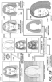
- FIGS. 5A and 5B are schematic diagrams of digital content projection methods for hair coloring or hair styling applications according to embodiments of inventive technology.
- the method may include only some of the steps in the FIGS. 5A and 5B , or may include additional steps that are not illustrated.
- method 5000A is an embodiment of the inventive technology for projecting a hair coloring and/or hair styling application (also referred to as "virtual hair coloration") onto user's hair.
- a camera input of the user's face and hair is obtained.
- a depth live input of the user's face and/or hair is acquired by, for example, the camera 24.
- This live input may be provided to block 330, where a camera to projector frame transformation is affected, and to block 525, where her segmentation and tracking is affected.
- the projector 22 may project her content onto the hair segmentation and tracking outline of the block 525.
- the resulting overlay of the health content projection over the hair of the user is shown in block 570.
- the health content projections of the block 560 may, for example, include different colors and/or different hairstyles.
- method 5000B is an embodiment of the inventive technology for projecting a hair coloring and/or hair styling application (also referred to as "virtual hair coloration") onto user's hair.
- a camera input of the user's face and hair is obtained.
- This camera input of block 520 may be processed in blocks 525A-525B, either alone or in conjunction with the depth live input of the block 315.
- the camera input of block 520 is converted into a hair segmentation outline.
- the tracking points e.g., landmarks 327) are defined.
- a 3D face model is overlaid over the camera input of block 520.
- some or all of the blocks 525A-525C are implemented.
- a 3D hair reconstruction and tracking is affected.
- content is created in a 3D space, and may be fed into the camera-to-projector frame transformation of the block 330.
- a hair content projection is created. In some embodiments, this hair content projection may be at least in part based on the makeup tutorials. The resulting application of the hair content projection over the hair of the user is shown in block 570.
- FIG. 6 is a perspective view of a digital content projection system according to one embodiment of inventive technology.
- the projector 22 may project makeup projections over, for example, half of the user's face (370 - R), while the other half of the user's face is free from the projections.
- the user 370 may observe the effect of the makeup projection on the mirror, a laptop, a processing unit 30, or other display units.
- the user may select different makeup embodiments to be projected to find a satisfactory projection.
- one type of the makeup e.g., an evening makeup
- another type of the makeup e.g., a daytime makeup
- the user may execute an analogues process for the head, with different hairstyles and/or colors attested through different images based on the makeup tutorial.
- the user may project makeup on one half of the face and use the projection as a guide for applying the makeup on the other side of the face.
- the inventive technology may be practiced by a person other than the user, for example, a cosmetologist, a makeup artist, etc.
- the accurate position of face is important since it is a non-rigid surface that needs to be tracked with a certain frequency. This can be done using different methods depending on the applications requirements. Some embodiments of such tracking are described below.
- the landmarks of the face are detected either directly by the RGB camera or by an infrared camera.
- the latter if coupled with a filter on the projector that cuts off infrared projection, provides robust landmarks that are not affected by the projected content, which may be useful for some applications.
- a 3D model may be fit on the face using either only the RGB information or by combining the RGB and the depth information.
- Such an embodiment has an additional computation cost, but, if based on depth, the approach may be more robust against variations on colors on the face due to projection.
- surface of the face may be reconstructed using the depth sensor image and additional detection of landmarks on that surface.
- landmarks may be detected using both the depth and RGB/infrared images as inputs to make the detection more robust to projection. Additionally, a deep learning algorithm could be trained on such a dataset.
- the face of the person may be scanned, and then tracked as combination of expressions (blend shapes) and pose orientation.
- RGB image is used for hair segmentation, using, for example, a deep learning algorithm. In some embodiments, such additional use of depth information makes the segmentation more accurate.
- the generation of the virtual content depends of the application scenario and the method used for face reconstruction/detection, It can be either simply based on the face landmarks and creating desired texture using this 2D topology, or it can be a texture mapped on the 3D face model if the latter is calculated.
- the systems 110, 120 project digital content onto a user's hair to create the illusion of hair color change. In an embodiment, this effect is combined with makeup projection to decide on optimal combinations.
- the user interacts with the systems 110, 120 using an interface with audio or manual inputs or by changing the colors or modifying the texture (highlights, patters, etc.).
- Makeup projection Makeup augmentation for easy trying of various products (limited by the environmental conditions). Projected products can be altered to take into account the effect of the physical application at the specific type of skin.
- Different lighting conditions simulation The effect of different lighting conditions can be simulated to visualize the appearance of makeup under different conditions (such as nightclub, daylight, office, etc.).
- Aging/Deaging simulation Augment and enhance wrinkles or skin exposure to make the person look older. This can be combined with skin care treatment and diagnosis. On the other hand, using light, wrinkles can be compensated and the person can look younger. This can simulate the expected result using a skin care product.
- Optical effects creation Create and simulate different optical effects on the face surface such as increase glossiness, smooth the face, pearl effect, increase contrast, transparency etc.
- the subsurface scattering can be modelled and taken into account in such a system in order to create more realistic effects.
- Traffic creation At the Point of Sale, such a system can increase significantly traffic by attracting people to get in the store once by having a system behind the window. They can be augmented with something "fun" once they pass by outside the store.
- Augment not only faces but also other objects: augment packaging of products that can be either real products or big mockups for visualization purposes.
- the system includes a makeup tutorial unit.
- the makeup tutorial unit is configured to project digital content including a makeup application tutorial onto the user's facial surface.
- the makeup tutorial unit includes a processor and computational circuitry configured to generate projectable makeup tutorial content responsive to receiving one or more parameters associated with a digital representation of the user's facial surface.
- the makeup tutorial unit is configured to generate a projection of a digital cosmetic application that tracks in real-time at least a partial three-dimensional or two-dimensional representation of the user's facial surface.
- the makeup tutorial unit 106 is configured to generate a projection of a digital cosmetic application that tracks in real-time to one or more facial landmarks.
- the makeup tutorial unit 106 includes a plurality of controllable light-emitting sources operable to generate a projectable display.
- the makeup tutorial unit includes a plurality of controllable light-emitting sources operable to project a makeup application tutorial onto the user's facial surface. Such projections may simulate a plurality of environmental lighting conditions.
- the makeup tutorial unit includes a plurality of controllable light-emitting sources operable to project at least a first virtual object and a second virtual object, the second virtual object indicative of different environmental lighting condition from the first virtual object.
- Non-limiting examples of controllable light-emitting sources 108 include one or more lasers, laser diodes, light-emitting diodes (LEDs), organic light emitting diodes (OLEDs), polymer light-emitting diodes, arc flashlamps, continuous wave bulbs, or incandescent emitters, and the like.
- the makeup tutorial unit has at least one of a red light-emitting source having an average peak emission wavelength ranging from 610 nanometers (nm) to 720 nm, a blue light-emitting source having an average peak emission wavelength ranging from 430 nm to 500 nm, and a green light-emitting source having an average peak emission wavelength ranging from 500 nm to 570 nm.
- the makeup tutorial unit includes a plurality of controllable laser diodes operable to generate a projectable display.
- the makeup tutorial unit includes at least one of a red laser diode having an average peak emission wavelength ranging from 610 nm to 720 nm, a blue laser diode having an average peak emission wavelength ranging from 430 nm to 500 nm, and a green laser diode having an average peak emission wavelength ranging from 500 nm to 570 nm.
- the makeup tutorial unit includes a plurality of controllable light-emitting sources and a Digital Micromirror Device (DMD) operable to project facially mapped, digitally generated, content representative of a makeup application process.
- the makeup tutorial unit includes a laser diode assembly operable to project a makeup application tutorial onto the user's facial surface responsive to receiving one or more parameters associated with a digital representation of the user's facial surface.
- the makeup tutorial unit includes at least one of a laser diode, a dichroic mirror, a mirror, a phosphor wheel, a color wheel, a Digital Micromirror Device (DMD) chip, a prism, or a projection lens assembly.
- DMD Digital Micromirror Device
- the makeup tutorial unit includes at least one liquid crystal display (LCD) projector.
- the makeup tutorial unit includes at least one ultra-miniature MEMS mirror operable to scan a modulated laser beam onto the user's facial surface.
- the dynamic distortion compensation unit is operably coupled to the makeup tutorial unit, and is configured to compensate in real-time illumination and geometrical distortions associated with the projected digital content including the makeup application tutorial.
- the dynamic distortion compensation unit includes a processor and computational circuitry configured to generate one or more illumination calibration parameters or geometrical calibration parameters responsive to receiving one or more inputs indicative of a detected distortion in a structured light projection, a structured code projection, a spatially or temporally-encoded pattern projection, or a light strip projection.
- the dynamic distortion compensation unit includes a processor and computational circuitry configured to modulate one or more digital images associated with the projected digital content including the makeup application tutorial responsive to receiving one or more inputs indicative of detected illumination distortions or geometrical distortions associated with the projected project digital content.
- the system includes a makeup tutorial unit and a depth-resolved image unit (e.g., depth camera 24 having one or more depth sensors).
- the makeup tutorial unit is configured to project a makeup application tutorial onto the user's facial surface responsive to receiving one or more parameters associated with a digital representation of the user's facial surface.
- the depth-resolved image unit is configured to generate a depth-resolved digital representation of a user's facial surface.
- the makeup tutorial unit is operably coupled to the depth-resolved image unit and is configured to project a makeup application tutorial onto the user's facial surface responsive to receiving one or more parameters associated with the depth-resolved digital representation of the user's facial surface.
- the depth-resolved image unit includes a processor and computational circuitry configured to generate the depth-resolved digital representation of the user's facial surface responsive to receiving one or more inputs indicative of a detected difference between an emitted light signal and a reflected light signal.
- the depth-resolved image unit includes at least one time-of-flight sensor configured to detected differences between an emitted light signal and a reflected light signal.
- the depth-resolved image unit at least one Doppler-effect transducer.
- the depth-resolved image unit includes a processor and computational circuitry configured to generate the depth-resolved digital representation of the user's facial surface responsive to receiving one or more inputs indicative of a detected distortional change in a projected light pattern.
- the depth-resolved image unit includes at least one of an infrared illuminator, an infrared sensor, an RGB (Red, Green, Blue) sensor, or a monochrome sensor.
- the depth-resolved image unit includes at least one infrared illuminator operable to project an infrared light pattern onto a user's facial surface, and at least one infrared sensor operable to detect distortional changes in the projected infrared light pattern.
- the depth-resolved image unit includes at least one infrared illuminator operable to project a spaced-apart infrared light pattern onto a user's facial surface, and at least one infrared sensor operable to detect distortional changes in the projected spaced-apart infrared light pattern.
- the depth-resolved image unit includes at least a pair of any of RGB (Red, Green, Blue), monochrome, infrared sensors, or the like, operable to estimate depth via triangulation.
- RGB Red, Green, Blue
- monochrome monochrome
- infrared sensors or the like
- the depth-resolved image unit includes one or more depth sensors.
- depth sensors include rolling shutter depth sensors, global shutter depth sensors, active depth sensing cameras, Charge Coupled Devices (CCD), Complementary Metal Oxide Semiconductors (CMOS), and the like.
- CCD Charge Coupled Devices
- CMOS Complementary Metal Oxide Semiconductors
- Further non-limiting examples of depth sensors include disparity sensors, time-of-flight sensor, stereo sensors, and the like.
- Further non-limiting examples of depth sensors include Intel RealSense sensors, Microsoft Kinect sensors, Qualcomm Depth Sensor, Asus Xtion Pro sensors, and the like.
- the depth-resolved image unit includes circuitry configured to project a structured light pattern and according to the displacement of this pattern, compute depth based on one or more input indicative of disparity in the structured light pattern.
- the depth-resolved image unit includes circuitry configured to detect the time that projected light bounces of the objects in the scene and to determine the distance from the objects.
- the depth-resolved image unit includes circuitry including a plurality of sensor (stereo module) configured to reconstruct a user's head, face, or body portion through triangulation.
- the depth-resolved image unit includes circuitry configured to project an infrared pattern to provide extra texture to ease the triangulation.
- the depth-resolved image unit includes a plurality of depth sensors, at least one RGB (Red, Green, Blue) sensor, and at least one infrared projector.
- the plurality of depth sensors includes at least one rolling shutter depth sensor.
- the plurality of depth sensors includes at least one global shutter depth sensor.
- the plurality of depth sensors includes at least one Charge Coupled Device (CCD).
- the plurality of depth sensors includes at least one Complementary Metal Oxide Semiconductor (CMOS).
- CMOS Complementary Metal Oxide Semiconductor
- the depth-resolved image unit includes at least one active depth sensing camera.
- the depth-resolved image unit includes a processor and computational circuitry configured to extract one or more facial landmarks from the depth-resolved digital representation of a user's facial surface, and to track the one or more of the facial landmarks extracted from the depth-resolved digital representation of the user's facial surface.
- the depth-resolved image unit is configured to extract one or more facial landmarks from the depth-resolved digital representation of a user's facial surface using at least one method of the following categories:
- depth resolved images can be generated by: holistic methods (such as Active Appearance Model (AAM), fitting algorithms or extensions), Constrained Local Model (CLM) methods (such as general or local appearance model, face shape model, detection by optimization etc.) and regression-based methods (direct, cascaded or deep-learning regression).
- the depth-resolved image unit is configured to perform a 3D reconstruction of at least a portion of the user's facial surface from the depth-resolved digital representation of a user's facial surface.
- the depth-resolved image unit is configured to extract one or more facial landmarks of a user's facial surface using any of the RGB, monochrome, infrared, depth live input.
- the depth-resolved image unit is configured to perform a 3D reconstruction of at least a portion of the user's facial surface using any of a RGB, monochrome, infrared, depth live input.
- the makeup tutorial unit is operably coupled to the coaxial optics unit and is configured to project a makeup application tutorial onto the user's facial surface responsive to receiving one or more parameters associated with the detected difference between the project digital content and the target digital content.
- the coaxial optics unit is configured to detect geometric and photometric differences between the projected digital content and the target digital content.
- the coaxial optics unit includes a beam splitter, a camera, and a projector.
- the coaxial optics unit includes a beam splitter, an image sensor, and a Digital Light Processing (DLP) projector.
- DLP Digital Light Processing
- Face detection/reconstruction The face accurate position is relevant since it is a non-rigid surface that is typically tracked with a high frequency. This can be done using different methods. Some examples of such methods are listed below.
- the landmarks are detected on the face by the RGB, monochrome, infrared camera, or the like.
- the latter if coupled with a filter on the projector that cuts off infrared projection, provides robust landmarks that are not affected by the projected content which is important for some applications.
- a 3D model is fitted on the face using either only the RGB information (for the landmarks) or combining the RGB and the depth information (obtained with depth sensors and technologies). This has an additional computation cost, but, if based on depth, it is more robust against variations on colors on the face due to projection.
- a surface reconstruction of the face uses the depth sensor image and additional detection of landmarks on that surface.
- the landmarks are detected using both the depth and RGB/infrared images as inputs to make the detection more robust to projection.
- a deep learning algorithm may be trained on such a dataset.
- Some embodiments include scanning the face of the person and then tracking it as a combination of expressions (blend shapes) and pose orientation.
- a virtual hair coloration system includes a processor and computational circuitry configured to generate projectable hair color content based at least on input associated with the one or more hair segments.
- the projectable hair color content includes one or more of a projectable hair color, a projectable hair texture, projectable hair color pattern, a projectable hair highlights pattern
- the digital hair projection unit includes a laser diode assembly operable to project at least a first virtual object and a second virtual object, the second virtual object indicative of different hair color condition from the first virtual object.
- the first virtual object comprises a first hair highlight color and the second virtual object comprises a second hair highlight color different from the first hair highlight color.
- the first virtual object comprises a first hair highlight pattern and the second virtual object comprises a second hair highlight pattern different from the first hair highlight pattern.
- the first virtual object comprises a first hair texture pattern and the second virtual object comprises a second hair texture pattern.
- the digital hair projection unit includes a laser diode assembly operable to project at least a first virtual object and a second virtual object, the second virtual object indicative of different environmental lighting condition from the first virtual object.
- the digital hair projection unit includes a laser diode assembly operable to project digital hair color content onto the of a user's head or body portion that mimics a change in hair color or hair texture.
- the digital hair projection unit includes a laser diode assembly operable to project digital hair color content onto the of a user's head or body portion that mimics a change in hair color or hair texture, under a plurality of environmental lighting conditions.
- the digital hair projection unit is further configured to project digital makeup content onto a portion of the user's face or body responsive to receiving one or more parameters associated a segmentation mask.
- a virtual hair coloration method includes: partitioning a digital representation of a user's head, face, or body portion into one or more of hair segments, face segments, skin segments, or background segments; and generating a virtual coloration segmentation mask.
- the virtual hair coloration method of claim 14 also includes generating projectable digital hair content responsive to receiving one or more inputs associated with the virtual coloration segmentation mask.
- the virtual hair coloration method also includes projecting the digital hair content onto a user.
- partitioning the digital representation of the user's head, face, or body portion into one or more of hair segments, face segments, skin segments, or background segments includes detecting one or more objects in digital representation of the user's head, face, or body portion, and
- the hair coloration method includes segmenting the objects into one or more of hair segments, face segments, skin segments, or background segments.
- the virtual hair coloration method also includes track at least one of the one or more objects.
- the virtual hair coloration method of claim 14 also includes generating a virtual makeup segmentation mask; and generating projectable digital makeup content responsive to receiving one or more inputs associated with the virtual makeup segmentation mask.
- Some embodiments include hair segmentation for some applications using the RGB image (for example a deep learning algorithm), or extra use of depth information to make the segmentation more accurate.
- circuitry to implement, for example, projection protocols, operably couple two or more components, generate information, determine operation conditions, control a device or method, or the like.
- Circuitry of any type can be used.
- circuitry includes, among other things, one or more computing devices such as a processor (e.g., a microprocessor), a central processing unit (CPU), a digital signal processor (DSP), an application-specific integrated circuit (ASIC), a field-programmable gate array (FPGA), or the like, or any combinations thereof, and can include discrete digital or analog circuit elements or electronics, or combinations thereof.
- circuitry includes one or more ASICs having a plurality of predefined logic components.
- circuitry includes one or more FPGA having a plurality of programmable logic components.
- circuitry includes one or more electric circuits, printed circuits, flexible circuits, electrical conductors, electrodes, cavity resonators, conducting traces, ceramic patterned electrodes, electro-mechanical components, transducers, and the like.
- circuitry includes one or more components operably coupled (e.g., communicatively, electromagnetically, magnetically, ultrasonically, optically, inductively, electrically, capacitively coupled, wirelessly coupled, and the like) to each other.
- circuitry includes one or more remotely located components.
- remotely located components are operably coupled, for example, via wireless communication.
- remotely located components are operably coupled, for example, via one or more communication modules, receivers, transmitters, transceivers, and the like.
- circuitry includes memory that, for example, stores instructions or information.
- memory includes volatile memory (e.g., Random Access Memory (RAM), Dynamic Random Access Memory (DRAM), and the like), non-volatile memory (e.g., Read-Only Memory (ROM), Electrically Erasable Programmable Read-Only Memory (EEPROM), Compact Disc Read-Only Memory (CD-ROM), and the like), persistent memory, and the like.
- RAM Random Access Memory
- DRAM Dynamic Random Access Memory
- EEPROM Electrically Erasable Programmable Read-Only Memory
- CD-ROM Compact Disc Read-Only Memory
- EPROM Erasable Programmable Read-Only Memory
- memory is coupled to, for example, one or more computing devices by one or more instructions, information, or power buses.
- circuitry includes one or more computer-readable media drives, interface sockets, Universal Serial Bus (USB) ports, memory card slots, and the like, and one or more input/output components such as, for example, a graphical user interface, a display, a keyboard, a keypad, a trackball, a joystick, a touch-screen, a mouse, a switch, a dial, and the like, and any other peripheral device.
- USB Universal Serial Bus
- circuitry includes one or more user input/output components that are operably coupled to at least one computing device configured to control (electrical, electromechanical, software-implemented, firmware-implemented, or other control, or combinations thereof) at least one parameter associated with, for example, determining one or more tissue thermal properties responsive to detected shifts in turn-ON voltage.
- control electrical, electromechanical, software-implemented, firmware-implemented, or other control, or combinations thereof
- circuitry includes a computer-readable media drive or memory slot that is configured to accept signal-bearing medium (e.g., computer-readable memory media, computer-readable recording media, and the like).
- signal-bearing medium e.g., computer-readable memory media, computer-readable recording media, and the like.
- a program for causing a system to execute any of the disclosed methods can be stored on, for example, a computer-readable recording medium, a signal-bearing medium, and the like.
- Non-limiting examples of signal-bearing media include a recordable type medium such as a magnetic tape, floppy disk, a hard disk drive, a Compact Disc (CD), a Digital Video Disk (DVD), Blu-Ray Disc, a digital tape, a computer memory, and the like, as well as transmission type medium such as a digital or an analog communication medium (e.g., a fiber optic cable, a waveguide, a wired communications link, a wireless communication link (e.g., receiver, transmitter, transceiver, transmission logic, reception logic, etc.).
- a recordable type medium such as a magnetic tape, floppy disk, a hard disk drive, a Compact Disc (CD), a Digital Video Disk (DVD), Blu-Ray Disc, a digital tape, a computer memory, and the like
- transmission type medium such as a digital or an analog communication medium (e.g., a fiber optic cable, a waveguide, a wired communications link, a wireless communication link (e.g
- signal-bearing media include, but are not limited to, DVD-ROM, DVD-RAM, DVD+RW, DVD-RW, DVD-R, DVD+R, CD-ROM, Super Audio CD, CD-R, CD+R, CD+RW, CD-RW, Video Compact Discs, Super Video Discs, flash memory, magnetic tape, magneto-optic disk, MINIDISC, non-volatile memory card, EEPROM, optical disk, optical storage, RAM, ROM, system memory, web server, and the like.
- circuitry includes acoustic transducers, electroacoustic transducers, electrochemical transducers, electromagnetic transducers, electromechanical transducers, electrostatic transducers, photoelectric transducers, radio-acoustic transducers, thermoelectric transducers, ultrasonic transducers, and the like.
- circuitry includes electrical circuitry operably coupled with a transducer (e.g., an actuator, a motor, a piezoelectric crystal, a Micro Electro Mechanical System (MEMS), etc.)
- circuitry includes electrical circuitry having at least one discrete electrical circuit, electrical circuitry having at least one integrated circuit, or electrical circuitry having at least one application specific integrated circuit.
- circuitry includes electrical circuitry forming a general purpose computing device configured by a computer program (e.g., a general purpose computer configured by a computer program which at least partially carries out processes and/or devices described herein, or a microprocessor configured by a computer program which at least partially carries out processes and/or devices described herein), electrical circuitry forming a memory device (e.g., forms of memory (e.g., random access, flash, read only, etc.)), electrical circuitry forming a communications device (e.g., a modem, communications switch, optical-electrical equipment, etc.), and/or any non-electrical analog thereto, such as optical or other analogs.
- a computer program e.g., a general purpose computer configured by a computer program which at least partially carries out processes and/or devices described herein, or a microprocessor configured by a computer program which at least partially carries out processes and/or devices described herein
- electrical circuitry forming a memory device e.g., forms of
Landscapes
- Engineering & Computer Science (AREA)
- Physics & Mathematics (AREA)
- Multimedia (AREA)
- General Physics & Mathematics (AREA)
- Signal Processing (AREA)
- Computer Vision & Pattern Recognition (AREA)
- Health & Medical Sciences (AREA)
- Theoretical Computer Science (AREA)
- General Health & Medical Sciences (AREA)
- Oral & Maxillofacial Surgery (AREA)
- Geometry (AREA)
- Medical Informatics (AREA)
- Radar, Positioning & Navigation (AREA)
- Software Systems (AREA)
- Databases & Information Systems (AREA)
- Computing Systems (AREA)
- Computer Networks & Wireless Communication (AREA)
- Electromagnetism (AREA)
- Evolutionary Computation (AREA)
- Remote Sensing (AREA)
- Artificial Intelligence (AREA)
- Human Computer Interaction (AREA)
- Length Measuring Devices By Optical Means (AREA)
- Processing Or Creating Images (AREA)
- Image Processing (AREA)
- Image Analysis (AREA)
- Cosmetics (AREA)
Abstract
Description
- In one embodiment, a virtual hair coloration system includes: a projector configured to project digital content including a makeup application tutorial onto the user's hair; and a dynamic mapping unit operably coupled to the projector, wherein the dynamic mapping unit is configured to establish a dynamic correspondence between pixels of the projector and features of the user's hair.
- In one aspect, the dynamic correspondence between the pixels of the projector and features of the user's hair is a first dynamic correspondence, and the dynamic mapping unit is configured to establish a second dynamic correspondence between the pixels of the projector and features of the user's face.
- In one aspect, the system also includes a dynamic distortion compensation unit operably coupled to the projector, where the dynamic distortion compensation unit is configured to compensate, in real-time, at least one of color distortions and geometrical distortions of the user's facial surface or the user's hair.
- In one aspect, the dynamic mapping unit includes a depth camera configured to dynamically determine a depth contour of the user's facial surface or the user's hair.
- In another aspect, the depth camera includes at least one of a time-of-flight sensor and a Doppler-effect transducer configured to determine the depth contour of the user's hair.
- In one aspect, the dynamic mapping unit includes a coaxial optics setup having a beam splitter, where the beam splitter is configured to direct an image of the user's facial surface or an image of the user's hair to a camera of the dynamic mapping unit, and where the projector is configured to project digital content including the makeup application tutorial onto the user's hair.
- In one aspect, the camera is a 2D camera, and the dynamic mapping is configured to establish the dynamic correspondence between individual pixels of the projector and features of the user's facial surface irrespective of a depth contour of the user's face or the user's hair.
- In one aspect, the projector is configured to project at least a first virtual object and a second virtual object, the second virtual object indicative of different environmental lighting condition from the first virtual object.
- In one aspect, the dynamic correspondence with the depth-resolved digital representation of the user's hair includes the dynamic correspondence with at least one facial landmark.
- In one aspect, the dynamic correspondence with the depth-resolved digital representation of the user's hair includes the dynamic correspondence with at least one partial three-dimensional representation of the user's hair.
- In one aspect, the dynamic correspondence with the depth-resolved digital representation of the user's hair includes the dynamic correspondence with at least one of a facial landmark, a wrinkle, a skinfold, or an anatomical feature in a facial image.
- In one embodiment, a method of projecting digital content including a makeup application tutorial onto a user includes: establishing, by a dynamic mapping unit, a dynamic correspondence between pixels of a projector and features of a user's hair, where the dynamic mapping unit is operably coupled to the projector; and projecting, by the projector, digital content including the makeup application tutorial onto the user's hair.
- In one aspect, establishing, by the dynamic mapping unit, the dynamic correspondence between pixels of the projector and features of the user's hair includes projecting a light pattern that comprises a structured light projection, a structured code projection, a light strip projection, a spatially-encoded pattern, a temporally-encoded pattern or a reference image projection.
- In one aspect, establishing, by the dynamic mapping unit, the dynamic correspondence between pixels of the projector and features of the user's hair includes generating a depth-resolved digital representation of at least a portion of the user's hair.
- In one aspect, projecting digital content including the makeup application tutorial includes projecting digitally generated, content representative of a hair styling process.
-
-
FIG. 1 is a schematic view of a digital content projection system according to one embodiment of inventive technology. -
FIG. 2 is a schematic view of a digital content projection system according to one embodiment of inventive technology. -
FIGS. 3A-3C are schematic diagrams of digital content projection methods for makeup applications according to embodiments of inventive technology. -
FIGS. 4A-4C are schematic diagrams of digital content projection methods for makeup applications according to embodiments of inventive technology. -
FIGS. 5A and5B are schematic diagrams of digital content projection methods for hair coloring or hair styling applications according to embodiments of inventive technology. -
FIG. 6 is a perspective view of a digital content projection system according to one embodiment of inventive technology. - In the following detailed description, reference is made to the accompanying drawings, which form a part hereof. In the drawings, similar symbols typically identify similar components, unless context dictates otherwise. The illustrative embodiments described in the detailed description, drawings, and claims are not meant to be limiting. Other embodiments may be utilized, and other changes may be made, without departing from the spirit or scope of the subject matter presented here.
-
FIG. 1 is a schematic view of a digitalcontent projection system 110 according to one embodiment of inventive technology. In different embodiments, the system 110 (e.g., a digital content projection system, an augmented reality system, a makeup tutorial system, a virtual hair coloration system, or the like) may include one or more methodologies or technologies that are implemented through, for example, projecting digital content onto a user, projecting digital hair content onto a user, projecting digital makeup content onto the user's head, face, or body portion, generating augmented realty content, or the like. For brevity and conciseness, these digital content projection systems, augmented reality systems, makeup tutorial systems, and/or virtual hair coloration system are herein referred to as the makeup tutorial systems. - In the illustrated embodiment, a
depth camera 24 acquires a depth-resolved image of user's 10 face. In different embodiments, thedepth camera 24 and appropriate image processing software (e.g., carried by theprocessing unit 30 and/or thecamera 24 itself) is referred to as a dynamic mapping unit. In an embodiment, thedepth camera 24 includes a depth sensor and circuitry configured to track in real-time at least a partial three-dimensional or two-dimensional representation of the user's head, face, or body portion. The image(s) acquired by thedepth camera 24 may be processed by a processing unit 30 (e.g., computer, smart phone, digital controller, etc.) to resolve the depth and outline of user's face. - The
depth camera 24 establishes a geometric calibration, since models are created (e.g., within the processing unit 30) for theprojector 22 and thedepth camera 24. Based on the model and through calibration, the parameters of these models can be estimated. Thus, using the live depth input and the models parameters thesystem 110 can dynamically (e.g., for each frame) establish correspondence between the projections of theprojector 22 and the depth outlines acquired by thedepth camera 24. - In an embodiment, a
projector 22 is configured to generate a projection of a digital cosmetic application onto user's face. In operation, pixels of thedigital projector 22 can track in real-time one or more landmarks/features of the user's face, as captured and resolved by thedepth camera 24. Theprojector 22 may also be connected with theprocessing unit 30 for coordination with the depth and outline of user's face obtained by thedepth camera 24. - In an embodiment, the
system 110 is configured to calibrate the projector and camera for real-time projections. In an embodiment, a depth sensor is operable to assess the three-dimensional (3D) positions of the camera pixels. In an embodiment, calibration between thedepth camera 24 and theprojector 22 can be achieved using different solutions. For example, starting from an optical model for the projector and the camera (which is the same but the light direction is opposite), a set of correspondences between two-dimensional (2D) points on the projector and camera images and 3D points in the scene are required to tune the parameters of the optical model. The shared principle is that the projector projects some coded information and the camera captures and decodes this information. - There are different methods to code this information (temporally/spatially encoded) and different assumptions on the setup and the number of poses required. As non-restrictive examples, some methods use a calibration target on which the coded information is projected, others just project on an arbitrary scene and in some cases the projection can be made on a planar surface. Using a planar surface may provide better results than the arbitrary scene (which may suffer from outliers due to pure decoding on complex surfaces, inter-reflections, etc.) while a projection on a planar surface may still provide a large set of robust points.
- In an embodiment, the
system 110 includes a dynamicdistortion compensation unit 26. In different embodiments, the dynamicdistortion compensation unit 26 adjusts for, for example, different pose of user's face, contortion of the face, movement of the lips, blinking of the eye, shaking of the hair, etc., such that theprojector 22 accounts for these dynamic changes on theuser 10. In different embodiments, the dynamicdistortion compensation unit 26 compensates in real-time for illumination and geometrical distortions associated with the projected digital content (possibly including the distortions associated with the makeup application tutorial). In one embodiment, the dynamic distortion compensation may include projecting dots, lines, shapes, areas, etc. on the face or hair of the user by theprojector 22. In some embodiments, the dynamicdistortion compensation unit 26 is operably coupled to theprojector 22 to compensate, in real-time, at least one of color distortions and geometrical distortions of the user's facial surface. In some embodiments, the dynamicdistortion compensation unit 26 executes corrections after the face is mapped (by, e.g., the depth camera 24) to enhance user experience. For example, photometric compensation may compensate for the different colors of the user's face in order to create a desired effect. Furthermore, the distortion compensation can be applied in using both thedepth camera 24 of thesystem 110 and a coaxial optics system of the system 120 (shown inFIG. 2 ). - In some embodiments, a
makeup tutorial 28 may project a digital content makeup content (e.g., through the digital projector 22) onto user's facial surface. Such digital content makeup content may include facially-mapped and digitally-generated content representative of a makeup application process, for example, the instructions for applying makeup, hair coloring or hair styling. In some embodiments, the makeup tutorial may be projected onto one eye as a guide, while the real makeup is being applied onto another eye. In different embodiments, multiple scenarios may be projected onto the face. For example, one set of makeup for a daytime wearing can be projected onto one side of the face, while another set of makeup for an evening event may be projected onto another side of the face. - During operation, the
system 110 may extract the shape and topology of the face of the user by thedepth camera 24, and may project a personalized makeup tutorial directly on the user's face by theprojector 22. The user can use a mirror to see the projection. In an embodiment, the makeup routine is gradually projected by defining the application zones of each product to be applied. In an embodiment, the user can apply real makeup using these zones. In an embodiment, the makeup application is digitally implemented (e.g., theprojector 22 is a digital projector). In an embodiment,user 10 interacts with an interface to proceed to the next product or to modify the experience. In an embodiment, the user can check the success of the application of a real product by comparing it with the projected virtual application zone. - In some embodiments, the user interacts with the system through an interface (tablet, smartphone, etc.). For various applications, the user may interact with an interface in order to take decisions on the projected content. For example, the user may select one from various proposed experiences (makeup tutorials, fun projection, storytelling, hair coloration, etc.), modify the experience (tuning the makeup, etc.), or control the process (go to or skip the next step, provide feedback that she/he finished the current session, etc.). This interface can be connected to the projected-camera system by either WiFi or through cable integrated in a final product.
- Data acquired by the
depth camera 24, data projected by theprojector 22, algorithms for data processing, makeup tutorials, etc., may be stored on theprocessing unit 30 or on a remote ("data cloud") system 50 - collectively, data storage systems. As described herein, the data storage systems may be any suitable device(s) configured to store data for access by a computing device. An example of the data storage system is a high-speed relational database management system (DBMS) executing on one or more computing devices and being accessible on the data cloud 50 over a high-speed network. However, other suitable storage techniques and/or devices capable of providing the stored data in response to queries may be used, and the computing device may be accessible locally instead of over a network, or may be provided as a cloud-based service. Thecloud storage system 50 may also include data stored in an organized manner on a computer-readable storage medium. - An accurate calibration between the
projector 22 and a depth sensor of thedepth camera 24 is important for the real-time projection. Moreover, thedepth camera 24 provides the 3D positions of the camera pixels. In some embodiments, the depth sensor may be configured separately from thedepth camera 24. - Starting from an optical model for the
projector 22 and the depth camera 24 (which may be the same but the light direction is opposite), a set of correspondences between 2D points on the projector and camera images and 3D points in the scene are required to tune the parameters of the optical model. The shared principle is that theprojector 22 projects some coded information and thedepth camera 24 captures and decodes this information. There are different methods to code this information (temporally/spatially encoded) and different assumptions on the setup and the number of poses required. Some methods use a calibration target on which the coded information is projected, others just project on an arbitrary 3D suface or a planar surface. The reason for using the planar surface is that it gives better results than the arbitrary scene (which suffers from outliers due to pure decoding on complex surfaces, interreflections etc.), and is still convenient to use providing a huge set of robust points. - Some non-exclusive examples of the depth sensors for the
depth camera 24 are the RealSense D415, Intel RealSense, Microsoft Kinect, Qualcomm Depth Sensor, and Asus Xtion Pro. For example, the first version Microsoft Kinect uses disparity sensors whereby a structured light pattern is projected (in infrared wavelength) and according to the displacement of this pattern, the depth is computed through disparity. As another example, the second version of Microsoft Kinect uses time-of-flight (still in infrared) to measure the time that projected light needs to reflect from the 3D objects in the scene to estimate distance to the objects. As yet another example, the Intel Realsense D series uses two sensors (stereo module) for the 3D reconstruction that is performed through triangulation. Furthermore, an optional projection of dotted infrared light provides extra texture to improve the triangulation. -
FIG. 2 is a schematic view of a digital content projection system 120 (e.g., a digital content projection system, an augmented reality system, a makeup tutorial system, a virtual hair coloration system, or the like) according to one embodiment of inventive technology. In some embodiments, the digitalcontent projection system 120 is referred to as a coaxial optics setup having abeam splitter 27. Thebeam splitter 27 may be capable of directing image of theuser 10 toward acamera 23, which may be a 2D camera. Thebeam splitter 27 can also allow digital projections from the projector 22 (e.g., makeup application scenarios, hair styling scenarios, makeup tutorials, etc.) to project onto theuser 10. - In operation, we need a dynamic correspondence between the pixels of the
projector 22 and thecamera 23. In some embodiments, thecoaxial optics system 120 may bypass the depth information due to a property of coaxial optics that a correspondence between theprojector 22 and thecamera 23 is depth-independent. Hence, it may be enough to register the correspondence between the projector and the camera once, since this correspondence remains unchanged with the moving scenes. In some embodiments, the parameters of the model do not need be computed. Instead, a relatively simpler process of calibration (e.g., establishing correspondence between the pixels of thecamera 23 and the projector 24) is performed. Using the depth camera of thesystem 110 ofFIG. 1 , a 3D scene may be established, which is useful for determining, e.g., facial features of the real 3D space. However, the coaxial optics of thesystem 120 ofFIG. 2 is generally faster due to less communication delay in the system. Furthermore, in some embodiments, it is possible to fit 3D models on the 2D representation of thecamera 23, thus making thesystem 120 achieve almost the same functionality as thedepth camera system 110. -
FIGS. 3A-3C are schematic diagrams of digital content projection methods for makeup applications according to embodiments of inventive technology. In some embodiments, the method may include only some of the steps in theFIGS. 3A-3C , or may include additional steps that are not illustrated. InFIG. 3A ,method 3000A is an embodiment of the inventive technology for projecting makeup on the user's face. With the illustratedmethod 3000A, a group of landmarks on the user's face are tracked on camera images. In particular, in block 320 a red/green/blue (RGB), gray scale or infrared live input is acquired by a camera (e.g., the camera 24). Inblock 325, a set of face landmarks (marked by the dots) are identified and tracked based on the live input acquired by camera inblock 320.Features 327 are non-limiting examples of such landmarks. Inblock 315, a depth live input of the user's face and/or hair is acquired by, for example, thecamera 24. Inblock 310, the camera and projector are mutually calibrated. Inblock 330, inputs from theblocks block 350, the projector space is generated having a set of face features outlined and prepared for defining zones of interest. Inblock 355, zones of interest are defined based uponprojector space 350. For example, one or more sub spaces of theprojector space 350 may be filled with the projection of makeup displayed over the face of user. Inblock 360, the makeup projection is outlined. In some embodiments, themakeup projection 360 may be based on a makeup tutorial. Inblock 370, themakeup projection 360 is applied over the face of the user. In some embodiments, the user may observe the makeup projection 316 on a mirror, a tablet or a similar device. Furthermore, the user may exchange different appearances in the makeup tutorial to, for example, better understand and decide among different choices. - In
FIG. 3B ,method 3000B is an embodiment of the inventive technology for projecting makeup on the user's face. The steps of themethod 3000B are based on a depth image obtained inblock 315. Inblock 325, face features are detected and tracked based upon the death image obtained inblock 315. In some embodiments, the remaining steps of themethod 3000B are analogous those of themethod 3000A. - In
FIG. 3C ,method 3000C is an embodiment of the inventive technology for projecting makeup on the user's face. In the illustrated embodiment, the face landmarks are detected and tracked using both 2D camera and 3D camera images (blocks block 315 is fed intoblock 325, where face landmarks detection and tracking is affected, and intoblock 330, where the camera-to-projector frame transformation is affected. -
FIGS. 4A-4C are schematic diagrams of digital content projection methods for makeup applications according to embodiments of inventive technology. In some embodiments, the method may include only some of the steps in theFIGS. 4A-4C , or may include additional steps that are not illustrated. InFIG. 4A ,method 4000A is an embodiment of the inventive technology for projecting makeup on the user's face. Inblock 410, a 3D face model (also referred to as a 3D deformable model) is generated. Inblock 325, the 3D face model is fitted over an image of the face of user. Inblock 412 projector space that includes the 3D face model is generated. Inblock 420, the database with the makeup textures is accessed, and the desired texture is overlaid over an image of the user's face. This desired texture is applied to the makeup projection of theblock 360 in conjunction with the projector space of theblock 412. In some embodiments, landmarks may be optionally fitted before fitting 3D mesh. - In
FIG. 4B ,method 4000B is an embodiment of the inventive technology for projecting makeup on the user's face. Inblock 325, a 3D mesh is overlaid over the representation of the user's face obtained in block 315 (e.g., by the depth camera 24). In the illustrated embodiment, fitting and tracking of 3D face mesh is based on the death image. In some embodiments, the landmarks may be optionally fitted before fitting the 3D mesh. - In
FIG. 4C ,method 4000C is an embodiment of the inventive technology for projecting makeup on the user's face. With themethod 4000C, fitting and tracking of a 3D face mesh includes both the camera image and the depth images. For example, block 330, that includes camera to projector frame transformation, is based upon the depth live input of theblock 315, camera input of theblock 320 and a 3D deformable model of theblock 410. -
FIGS. 5A and5B are schematic diagrams of digital content projection methods for hair coloring or hair styling applications according to embodiments of inventive technology. In some embodiments, the method may include only some of the steps in theFIGS. 5A and5B , or may include additional steps that are not illustrated. InFIG. 5A ,method 5000A is an embodiment of the inventive technology for projecting a hair coloring and/or hair styling application (also referred to as "virtual hair coloration") onto user's hair. Inblock 520, a camera input of the user's face and hair is obtained. Inblock 315, a depth live input of the user's face and/or hair is acquired by, for example, thecamera 24. This live input may be provided to block 330, where a camera to projector frame transformation is affected, and to block 525, where her segmentation and tracking is affected. Inblock 560, theprojector 22 may project her content onto the hair segmentation and tracking outline of theblock 525. The resulting overlay of the health content projection over the hair of the user is shown inblock 570. In different embodiments, the health content projections of theblock 560 may, for example, include different colors and/or different hairstyles. - In
FIG. 5B ,method 5000B is an embodiment of the inventive technology for projecting a hair coloring and/or hair styling application (also referred to as "virtual hair coloration") onto user's hair. Inblock 520, a camera input of the user's face and hair is obtained. This camera input ofblock 520 may be processed inblocks 525A-525B, either alone or in conjunction with the depth live input of theblock 315. Inblock 525A, the camera input ofblock 520 is converted into a hair segmentation outline. Inblock 525B, the tracking points (e.g., landmarks 327) are defined. Inblock 525C, a 3D face model is overlaid over the camera input ofblock 520. In different embodiments, some or all of theblocks 525A-525C are implemented. Inblock 535, a 3D hair reconstruction and tracking is affected. Inblock 545, content is created in a 3D space, and may be fed into the camera-to-projector frame transformation of theblock 330. Inblock 560, a hair content projection is created. In some embodiments, this hair content projection may be at least in part based on the makeup tutorials. The resulting application of the hair content projection over the hair of the user is shown inblock 570. -
FIG. 6 is a perspective view of a digital content projection system according to one embodiment of inventive technology. In some embodiments, theprojector 22 may project makeup projections over, for example, half of the user's face (370 - R), while the other half of the user's face is free from the projections. Theuser 370 may observe the effect of the makeup projection on the mirror, a laptop, aprocessing unit 30, or other display units. The user may select different makeup embodiments to be projected to find a satisfactory projection. In some embodiments, one type of the makeup (e.g., an evening makeup) is projected on one side of the face, and another type of the makeup (e.g., a daytime makeup) is projected on the other side of the face. In different embodiments, the user may execute an analogues process for the head, with different hairstyles and/or colors attested through different images based on the makeup tutorial. In other embodiments, the user may project makeup on one half of the face and use the projection as a guide for applying the makeup on the other side of the face. In the descriptions herein, the inventive technology may be practiced by a person other than the user, for example, a cosmetologist, a makeup artist, etc. - The accurate position of face is important since it is a non-rigid surface that needs to be tracked with a certain frequency. This can be done using different methods depending on the applications requirements. Some embodiments of such tracking are described below.
- In one embodiment, the landmarks of the face are detected either directly by the RGB camera or by an infrared camera. The latter, if coupled with a filter on the projector that cuts off infrared projection, provides robust landmarks that are not affected by the projected content, which may be useful for some applications.
- In another embodiment, a 3D model may be fit on the face using either only the RGB information or by combining the RGB and the depth information. Such an embodiment has an additional computation cost, but, if based on depth, the approach may be more robust against variations on colors on the face due to projection.
- In another embodiment, surface of the face may be reconstructed using the depth sensor image and additional detection of landmarks on that surface.
- In one embodiments, landmarks may be detected using both the depth and RGB/infrared images as inputs to make the detection more robust to projection. Additionally, a deep learning algorithm could be trained on such a dataset.
- In one embodiment, the face of the person (user) may be scanned, and then tracked as combination of expressions (blend shapes) and pose orientation.
- In one embodiment, RGB image is used for hair segmentation, using, for example, a deep learning algorithm. In some embodiments, such additional use of depth information makes the segmentation more accurate.
- The generation of the virtual content depends of the application scenario and the method used for face reconstruction/detection, It can be either simply based on the face landmarks and creating desired texture using this 2D topology, or it can be a texture mapped on the 3D face model if the latter is calculated.
- In an embodiment, during operation, the
systems systems systems - Makeup projection: Makeup augmentation for easy trying of various products (limited by the environmental conditions). Projected products can be altered to take into account the effect of the physical application at the specific type of skin.
- Storytelling: For special events, extreme augmentations can be proposed such as the ones used on stage in theater/concerts to tell a story about a new launch of a brand or for the wow factor these immersive experiences can provide.
- Different lighting conditions simulation: The effect of different lighting conditions can be simulated to visualize the appearance of makeup under different conditions (such as nightclub, daylight, office, etc.).
- Aging/Deaging simulation: Augment and enhance wrinkles or skin exposure to make the person look older. This can be combined with skin care treatment and diagnosis. On the other hand, using light, wrinkles can be compensated and the person can look younger. This can simulate the expected result using a skin care product.
- Optical effects creation: Create and simulate different optical effects on the face surface such as increase glossiness, smooth the face, pearl effect, increase contrast, transparency etc. The subsurface scattering can be modelled and taken into account in such a system in order to create more realistic effects.
- Traffic creation: At the Point of Sale, such a system can increase significantly traffic by attracting people to get in the store once by having a system behind the window. They can be augmented with something "fun" once they pass by outside the store.
- Augment not only faces but also other objects: augment packaging of products that can be either real products or big mockups for visualization purposes.
- In an embodiment, the system includes a makeup tutorial unit. In an embodiment, the makeup tutorial unit is configured to project digital content including a makeup application tutorial onto the user's facial surface. For example, in an embodiment, the makeup tutorial unit includes a processor and computational circuitry configured to generate projectable makeup tutorial content responsive to receiving one or more parameters associated with a digital representation of the user's facial surface.
- In an embodiment, the makeup tutorial unit is configured to generate a projection of a digital cosmetic application that tracks in real-time at least a partial three-dimensional or two-dimensional representation of the user's facial surface. In an embodiment, the makeup tutorial unit 106 is configured to generate a projection of a digital cosmetic application that tracks in real-time to one or more facial landmarks.
- In an embodiment, the makeup tutorial unit 106 includes a plurality of controllable light-emitting sources operable to generate a projectable display. For example, in an embodiment, the makeup tutorial unit includes a plurality of controllable light-emitting sources operable to project a makeup application tutorial onto the user's facial surface. Such projections may simulate a plurality of environmental lighting conditions. In an embodiment, the makeup tutorial unit includes a plurality of controllable light-emitting sources operable to project at least a first virtual object and a second virtual object, the second virtual object indicative of different environmental lighting condition from the first virtual object.
- Non-limiting examples of controllable light-emitting sources 108 include one or more lasers, laser diodes, light-emitting diodes (LEDs), organic light emitting diodes (OLEDs), polymer light-emitting diodes, arc flashlamps, continuous wave bulbs, or incandescent emitters, and the like. In an embodiment, the makeup tutorial unit has at least one of a red light-emitting source having an average peak emission wavelength ranging from 610 nanometers (nm) to 720 nm, a blue light-emitting source having an average peak emission wavelength ranging from 430 nm to 500 nm, and a green light-emitting source having an average peak emission wavelength ranging from 500 nm to 570 nm.
- In an embodiment, the makeup tutorial unit includes a plurality of controllable laser diodes operable to generate a projectable display. In an embodiment, the makeup tutorial unit includes at least one of a red laser diode having an average peak emission wavelength ranging from 610 nm to 720 nm, a blue laser diode having an average peak emission wavelength ranging from 430 nm to 500 nm, and a green laser diode having an average peak emission wavelength ranging from 500 nm to 570 nm.
- In an embodiment, the makeup tutorial unit includes a plurality of controllable light-emitting sources and a Digital Micromirror Device (DMD) operable to project facially mapped, digitally generated, content representative of a makeup application process. In an embodiment, the makeup tutorial unit includes a laser diode assembly operable to project a makeup application tutorial onto the user's facial surface responsive to receiving one or more parameters associated with a digital representation of the user's facial surface. In an embodiment, the makeup tutorial unit includes at least one of a laser diode, a dichroic mirror, a mirror, a phosphor wheel, a color wheel, a Digital Micromirror Device (DMD) chip, a prism, or a projection lens assembly.
- In an embodiment, the makeup tutorial unit includes at least one liquid crystal display (LCD) projector. In an embodiment, the makeup tutorial unit includes at least one ultra-miniature MEMS mirror operable to scan a modulated laser beam onto the user's facial surface.
- In an embodiment, the dynamic distortion compensation unit is operably coupled to the makeup tutorial unit, and is configured to compensate in real-time illumination and geometrical distortions associated with the projected digital content including the makeup application tutorial. In an embodiment, the dynamic distortion compensation unit includes a processor and computational circuitry configured to generate one or more illumination calibration parameters or geometrical calibration parameters responsive to receiving one or more inputs indicative of a detected distortion in a structured light projection, a structured code projection, a spatially or temporally-encoded pattern projection, or a light strip projection. In an embodiment, the dynamic distortion compensation unit includes a processor and computational circuitry configured to modulate one or more digital images associated with the projected digital content including the makeup application tutorial responsive to receiving one or more inputs indicative of detected illumination distortions or geometrical distortions associated with the projected project digital content.
- In an embodiment, the system includes a makeup tutorial unit and a depth-resolved image unit (e.g.,
depth camera 24 having one or more depth sensors). In an embodiment, the makeup tutorial unit is configured to project a makeup application tutorial onto the user's facial surface responsive to receiving one or more parameters associated with a digital representation of the user's facial surface. - In an embodiment, the depth-resolved image unit is configured to generate a depth-resolved digital representation of a user's facial surface. In an embodiment, the makeup tutorial unit is operably coupled to the depth-resolved image unit and is configured to project a makeup application tutorial onto the user's facial surface responsive to receiving one or more parameters associated with the depth-resolved digital representation of the user's facial surface.
- In an embodiment, the depth-resolved image unit includes a processor and computational circuitry configured to generate the depth-resolved digital representation of the user's facial surface responsive to receiving one or more inputs indicative of a detected difference between an emitted light signal and a reflected light signal.
- In an embodiment, the depth-resolved image unit includes at least one time-of-flight sensor configured to detected differences between an emitted light signal and a reflected light signal.
- In an embodiment, the depth-resolved image unit at least one Doppler-effect transducer.
- In an embodiment, the depth-resolved image unit includes a processor and computational circuitry configured to generate the depth-resolved digital representation of the user's facial surface responsive to receiving one or more inputs indicative of a detected distortional change in a projected light pattern.
- In an embodiment, the depth-resolved image unit includes at least one of an infrared illuminator, an infrared sensor, an RGB (Red, Green, Blue) sensor, or a monochrome sensor.
- In an embodiment, the depth-resolved image unit includes at least one infrared illuminator operable to project an infrared light pattern onto a user's facial surface, and at least one infrared sensor operable to detect distortional changes in the projected infrared light pattern.
- In an embodiment, the depth-resolved image unit includes at least one infrared illuminator operable to project a spaced-apart infrared light pattern onto a user's facial surface, and at least one infrared sensor operable to detect distortional changes in the projected spaced-apart infrared light pattern.
- In an embodiment, the depth-resolved image unit includes at least a pair of any of RGB (Red, Green, Blue), monochrome, infrared sensors, or the like, operable to estimate depth via triangulation.
- In an embodiment, the depth-resolved image unit includes one or more depth sensors. Non-limiting examples of depth sensors include rolling shutter depth sensors, global shutter depth sensors, active depth sensing cameras, Charge Coupled Devices (CCD), Complementary Metal Oxide Semiconductors (CMOS), and the like. Further non-limiting examples of depth sensors include disparity sensors, time-of-flight sensor, stereo sensors, and the like. Further non-limiting examples of depth sensors include Intel RealSense sensors, Microsoft Kinect sensors, Qualcomm Depth Sensor, Asus Xtion Pro sensors, and the like.
- In an embodiment, the depth-resolved image unit includes circuitry configured to project a structured light pattern and according to the displacement of this pattern, compute depth based on one or more input indicative of disparity in the structured light pattern. In an embodiment, the depth-resolved image unit includes circuitry configured to detect the time that projected light bounces of the objects in the scene and to determine the distance from the objects. In an embodiment, the depth-resolved image unit includes circuitry including a plurality of sensor (stereo module) configured to reconstruct a user's head, face, or body portion through triangulation. In an embodiment, the depth-resolved image unit includes circuitry configured to project an infrared pattern to provide extra texture to ease the triangulation.
- In an embodiment, the depth-resolved image unit includes a plurality of depth sensors, at least one RGB (Red, Green, Blue) sensor, and at least one infrared projector. In an embodiment, the plurality of depth sensors includes at least one rolling shutter depth sensor. In an embodiment, the plurality of depth sensors includes at least one global shutter depth sensor. In an embodiment, the plurality of depth sensors includes at least one Charge Coupled Device (CCD). In an embodiment, the plurality of depth sensors includes at least one Complementary Metal Oxide Semiconductor (CMOS). In an embodiment, the depth-resolved image unit includes at least one active depth sensing camera.
- In an embodiment, the depth-resolved image unit includes a processor and computational circuitry configured to extract one or more facial landmarks from the depth-resolved digital representation of a user's facial surface, and to track the one or more of the facial landmarks extracted from the depth-resolved digital representation of the user's facial surface.
- In an embodiment, the depth-resolved image unit is configured to extract one or more facial landmarks from the depth-resolved digital representation of a user's facial surface using at least one method of the following categories:
In different embodiments, depth resolved images can be generated by: holistic methods (such as Active Appearance Model (AAM), fitting algorithms or extensions), Constrained Local Model (CLM) methods (such as general or local appearance model, face shape model, detection by optimization etc.) and regression-based methods (direct, cascaded or deep-learning regression). - In an embodiment, the depth-resolved image unit is configured to perform a 3D reconstruction of at least a portion of the user's facial surface from the depth-resolved digital representation of a user's facial surface.
- In an embodiment, the depth-resolved image unit is configured to extract one or more facial landmarks of a user's facial surface using any of the RGB, monochrome, infrared, depth live input.
- In an embodiment, the depth-resolved image unit is configured to perform a 3D reconstruction of at least a portion of the user's facial surface using any of a RGB, monochrome, infrared, depth live input.
- In an embodiment, the makeup tutorial unit is operably coupled to the coaxial optics unit and is configured to project a makeup application tutorial onto the user's facial surface responsive to receiving one or more parameters associated with the detected difference between the project digital content and the target digital content.
- In an embodiment, the coaxial optics unit is configured to detect geometric and photometric differences between the projected digital content and the target digital content.
- In an embodiment, the coaxial optics unit includes a beam splitter, a camera, and a projector.
- In an embodiment, the coaxial optics unit includes a beam splitter, an image sensor, and a Digital Light Processing (DLP) projector.
- Face detection/reconstruction: The face accurate position is relevant since it is a non-rigid surface that is typically tracked with a high frequency. This can be done using different methods. Some examples of such methods are listed below.
- In some embodiments, the landmarks are detected on the face by the RGB, monochrome, infrared camera, or the like. The latter, if coupled with a filter on the projector that cuts off infrared projection, provides robust landmarks that are not affected by the projected content which is important for some applications.
- In some embodiments, a 3D model is fitted on the face using either only the RGB information (for the landmarks) or combining the RGB and the depth information (obtained with depth sensors and technologies). This has an additional computation cost, but, if based on depth, it is more robust against variations on colors on the face due to projection.
- In some embodiments, a surface reconstruction of the face uses the depth sensor image and additional detection of landmarks on that surface.
- In some embodiments, the landmarks are detected using both the depth and RGB/infrared images as inputs to make the detection more robust to projection. In some embodiments, a deep learning algorithm may be trained on such a dataset.
- Some embodiments include scanning the face of the person and then tracking it as a combination of expressions (blend shapes) and pose orientation.
- In one embodiment, a virtual hair coloration system includes a processor and computational circuitry configured to generate projectable hair color content based at least on input associated with the one or more hair segments.
- In one embodiment, the projectable hair color content includes one or more of a projectable hair color, a projectable hair texture, projectable hair color pattern, a projectable hair highlights pattern,
In one embodiment, the digital hair projection unit includes a laser diode assembly operable to project at least a first virtual object and a second virtual object, the second virtual object indicative of different hair color condition from the first virtual object. - In one embodiment, the first virtual object comprises a first hair highlight color and the second virtual object comprises a second hair highlight color different from the first hair highlight color.
- In one embodiment, the first virtual object comprises a first hair highlight pattern and the second virtual object comprises a second hair highlight pattern different from the first hair highlight pattern.
- In one embodiment, the first virtual object comprises a first hair texture pattern and the second virtual object comprises a second hair texture pattern.
- In one embodiment, the digital hair projection unit includes a laser diode assembly operable to project at least a first virtual object and a second virtual object, the second virtual object indicative of different environmental lighting condition from the first virtual object.
- In one embodiment, the digital hair projection unit includes a laser diode assembly operable to project digital hair color content onto the of a user's head or body portion that mimics a change in hair color or hair texture.
- In one embodiment, the digital hair projection unit includes a laser diode assembly operable to project digital hair color content onto the of a user's head or body portion that mimics a change in hair color or hair texture, under a plurality of environmental lighting conditions.
- In one embodiment, the digital hair projection unit is further configured to project digital makeup content onto a portion of the user's face or body responsive to receiving one or more parameters associated a segmentation mask.
- In one embodiment, a virtual hair coloration method includes: partitioning a digital representation of a user's head, face, or body portion into one or more of hair segments, face segments, skin segments, or background segments; and generating a virtual coloration segmentation mask.
- In one embodiment, the virtual hair coloration method of claim 14 also includes generating projectable digital hair content responsive to receiving one or more inputs associated with the virtual coloration segmentation mask.
- In one embodiment, the virtual hair coloration method also includes projecting the digital hair content onto a user.
- In one embodiment, partitioning the digital representation of the user's head, face, or body portion into one or more of hair segments, face segments, skin segments, or background segments includes detecting one or more objects in digital representation of the user's head, face, or body portion, and
In one embodiment, the hair coloration method includes segmenting the objects into one or more of hair segments, face segments, skin segments, or background segments. - In one embodiment, the virtual hair coloration method also includes track at least one of the one or more objects.
- In one embodiment, the virtual hair coloration method of claim 14 also includes generating a virtual makeup segmentation mask; and generating projectable digital makeup content responsive to receiving one or more inputs associated with the virtual makeup segmentation mask.
- Some embodiments include hair segmentation for some applications using the RGB image (for example a deep learning algorithm), or extra use of depth information to make the segmentation more accurate.
- Certain embodiments disclosed herein utilize circuitry to implement, for example, projection protocols, operably couple two or more components, generate information, determine operation conditions, control a device or method, or the like. Circuitry of any type can be used. In an embodiment, circuitry includes, among other things, one or more computing devices such as a processor (e.g., a microprocessor), a central processing unit (CPU), a digital signal processor (DSP), an application-specific integrated circuit (ASIC), a field-programmable gate array (FPGA), or the like, or any combinations thereof, and can include discrete digital or analog circuit elements or electronics, or combinations thereof. In an embodiment, circuitry includes one or more ASICs having a plurality of predefined logic components. In an embodiment, circuitry includes one or more FPGA having a plurality of programmable logic components.
- In an embodiment, circuitry includes one or more electric circuits, printed circuits, flexible circuits, electrical conductors, electrodes, cavity resonators, conducting traces, ceramic patterned electrodes, electro-mechanical components, transducers, and the like.
- In an embodiment, circuitry includes one or more components operably coupled (e.g., communicatively, electromagnetically, magnetically, ultrasonically, optically, inductively, electrically, capacitively coupled, wirelessly coupled, and the like) to each other. In an embodiment, circuitry includes one or more remotely located components. In an embodiment, remotely located components are operably coupled, for example, via wireless communication. In an embodiment, remotely located components are operably coupled, for example, via one or more communication modules, receivers, transmitters, transceivers, and the like.
- In an embodiment, circuitry includes memory that, for example, stores instructions or information. Non-limiting examples of memory include volatile memory (e.g., Random Access Memory (RAM), Dynamic Random Access Memory (DRAM), and the like), non-volatile memory (e.g., Read-Only Memory (ROM), Electrically Erasable Programmable Read-Only Memory (EEPROM), Compact Disc Read-Only Memory (CD-ROM), and the like), persistent memory, and the like. Further non-limiting examples of memory include Erasable Programmable Read-Only Memory (EPROM), flash memory, and the like. In an embodiment, memory is coupled to, for example, one or more computing devices by one or more instructions, information, or power buses.
- In an embodiment, circuitry includes one or more computer-readable media drives, interface sockets, Universal Serial Bus (USB) ports, memory card slots, and the like, and one or more input/output components such as, for example, a graphical user interface, a display, a keyboard, a keypad, a trackball, a joystick, a touch-screen, a mouse, a switch, a dial, and the like, and any other peripheral device. In an embodiment, circuitry includes one or more user input/output components that are operably coupled to at least one computing device configured to control (electrical, electromechanical, software-implemented, firmware-implemented, or other control, or combinations thereof) at least one parameter associated with, for example, determining one or more tissue thermal properties responsive to detected shifts in turn-ON voltage.
- In an embodiment, circuitry includes a computer-readable media drive or memory slot that is configured to accept signal-bearing medium (e.g., computer-readable memory media, computer-readable recording media, and the like). In an embodiment, a program for causing a system to execute any of the disclosed methods can be stored on, for example, a computer-readable recording medium, a signal-bearing medium, and the like. Non-limiting examples of signal-bearing media include a recordable type medium such as a magnetic tape, floppy disk, a hard disk drive, a Compact Disc (CD), a Digital Video Disk (DVD), Blu-Ray Disc, a digital tape, a computer memory, and the like, as well as transmission type medium such as a digital or an analog communication medium (e.g., a fiber optic cable, a waveguide, a wired communications link, a wireless communication link (e.g., receiver, transmitter, transceiver, transmission logic, reception logic, etc.). Further non-limiting examples of signal-bearing media include, but are not limited to, DVD-ROM, DVD-RAM, DVD+RW, DVD-RW, DVD-R, DVD+R, CD-ROM, Super Audio CD, CD-R, CD+R, CD+RW, CD-RW, Video Compact Discs, Super Video Discs, flash memory, magnetic tape, magneto-optic disk, MINIDISC, non-volatile memory card, EEPROM, optical disk, optical storage, RAM, ROM, system memory, web server, and the like.
- In an embodiment, circuitry includes acoustic transducers, electroacoustic transducers, electrochemical transducers, electromagnetic transducers, electromechanical transducers, electrostatic transducers, photoelectric transducers, radio-acoustic transducers, thermoelectric transducers, ultrasonic transducers, and the like.
- In an embodiment, circuitry includes electrical circuitry operably coupled with a transducer (e.g., an actuator, a motor, a piezoelectric crystal, a Micro Electro Mechanical System (MEMS), etc.) In an embodiment, circuitry includes electrical circuitry having at least one discrete electrical circuit, electrical circuitry having at least one integrated circuit, or electrical circuitry having at least one application specific integrated circuit. In an embodiment, circuitry includes electrical circuitry forming a general purpose computing device configured by a computer program (e.g., a general purpose computer configured by a computer program which at least partially carries out processes and/or devices described herein, or a microprocessor configured by a computer program which at least partially carries out processes and/or devices described herein), electrical circuitry forming a memory device (e.g., forms of memory (e.g., random access, flash, read only, etc.)), electrical circuitry forming a communications device (e.g., a modem, communications switch, optical-electrical equipment, etc.), and/or any non-electrical analog thereto, such as optical or other analogs.
Claims (13)
- A virtual hair coloration system, comprising:a projector (22) configured to project digital content including projectable hair color content onto the user's hair; anda dynamic mapping unit (24; 30) operably coupled to the projector, wherein the dynamic mapping unit is configured to establish a dynamic correspondence between pixels of the projector (22) and features of the user's hair,
andwherein the virtual hair coloration system is configured to:- partition a digital representation of a user's head into a plurality of hair segments and generate a virtual coloration segmentation mask and,- generate said projectable hair color content based at least on input associated with the plurality of hair segments, wherein said projectable hair color content includes instructions for applying hair coloring. - The system according to claim 1, further comprising:
a dynamic distortion compensation unit (26) operably coupled to the projector (22), wherein the dynamic distortion compensation unit (26) is configured to compensate, in real-time, at least one of color distortions and geometrical distortions of the user's facial surface or the user's hair. - The system according to any of the preceding claims, wherein the dynamic mapping unit (24; 30) comprises a depth camera configured to dynamically determine a depth contour of the user's facial surface or the user's hair, wherein the depth-camera is a depth-resolved image unit configured to generate a depth-resolved digital representation of a user's facial surface.
- The system according to claim 3, wherein the depth camera comprises at least one of a time-of-flight sensor and a Doppler-effect transducer configured to determine the depth contour of the user's hair.
- The system according to any of the preceding claims, wherein the dynamic mapping unit (24; 30) comprises a coaxial optics setup having a beam splitter (27), wherein the beam splitter (27) is configured to direct an image of the user's facial surface or an image of the user's hair to a camera of the dynamic mapping unit, and wherein the projector is configured to project digital content including the makeup application tutorial onto the user's hair.
- The system according to claim 5, wherein the camera is a 2D camera, and wherein the dynamic mapping (24; 30) is configured to establish the dynamic correspondence between individual pixels of the projector and features of the user's facial surface irrespective of a depth contour of the user's face or the user's hair.
- The system according to any of the preceding claims in combination with claim 3, wherein the dynamic correspondence with the depth-resolved digital representation of the user's facial surface includes the dynamic correspondence with at least one facial landmark.
- The system according to any of the preceding claims in combination with claim 3, wherein the dynamic correspondence with the depth-resolved digital representation of the user's facial surface includes the dynamic correspondence with at least one of a facial landmark, a wrinkle, a skinfold, or an anatomical feature in a facial image.
- The system according to any of the preceding claims, wherein the digital content comprises a first hair projection projected to one side of the user's hair and a second hair projection projected to another side of the user's hair, and wherein the first hair projection is different from the second hair projections.
- A method of projecting digital content including projectable hair color content onto a user, comprising:establishing, by a dynamic mapping unit, a dynamic correspondence between pixels of a projector and features of a user's hair, wherein the dynamic mapping unit is operably coupled to the projector; andprojecting, by the projector, digital content including the makeup application tutorial onto the user's hair,
andwherein the method of projecting digital content comprises:- partitioning a digital representation of a user's head into a plurality of hair segments and generating a virtual coloration segmentation mask, and- generating said projectable hair content based at least on input associated with the plurality of hair segments, wherein said projectable hair color content includes instructions for applying hair coloring. - The method according to claim 10, wherein establishing, by the dynamic mapping unit, the dynamic correspondence between the pixels of the projector and the features of the user's hair includes projecting a light pattern that comprises a structured light projection, a structured code projection, a light strip projection, a spatially-encoded pattern, a temporally-encoded pattern or a reference image projection.
- The method according to claim 10 or 11, further comprising establishing a dynamic correspondence between the pixels of the projector and features of the user's face, wherein establishing, by the dynamic mapping unit, the dynamic correspondence between the pixels of the projector and features of the user's face includes generating a depth-resolved digital representation of at least a portion of the user's facial surface.
- The method according to any of the preceding claims 10 to 12, wherein projecting digital content including the makeup application tutorial includes projecting digitally generated, content representative of a hair styling process.
Priority Applications (1)
| Application Number | Priority Date | Filing Date | Title |
|---|---|---|---|
| EP22199825.5A EP4138389B1 (en) | 2019-03-13 | 2019-03-13 | Projection of hair color and hair color tutorials directly on people's faces, and associated systems and methods |
Applications Claiming Priority (2)
| Application Number | Priority Date | Filing Date | Title |
|---|---|---|---|
| EP22199825.5A EP4138389B1 (en) | 2019-03-13 | 2019-03-13 | Projection of hair color and hair color tutorials directly on people's faces, and associated systems and methods |
| EP19305302.2A EP3709637B1 (en) | 2019-03-13 | 2019-03-13 | System and method for projecting digital content including hair color changes onto a user's head |
Related Parent Applications (1)
| Application Number | Title | Priority Date | Filing Date |
|---|---|---|---|
| EP19305302.2A Division EP3709637B1 (en) | 2019-03-13 | 2019-03-13 | System and method for projecting digital content including hair color changes onto a user's head |
Publications (3)
| Publication Number | Publication Date |
|---|---|
| EP4138389A1 true EP4138389A1 (en) | 2023-02-22 |
| EP4138389C0 EP4138389C0 (en) | 2024-01-03 |
| EP4138389B1 EP4138389B1 (en) | 2024-01-03 |
Family
ID=65818494
Family Applications (2)
| Application Number | Title | Priority Date | Filing Date |
|---|---|---|---|
| EP22199825.5A Active EP4138389B1 (en) | 2019-03-13 | 2019-03-13 | Projection of hair color and hair color tutorials directly on people's faces, and associated systems and methods |
| EP19305302.2A Active EP3709637B1 (en) | 2019-03-13 | 2019-03-13 | System and method for projecting digital content including hair color changes onto a user's head |
Family Applications After (1)
| Application Number | Title | Priority Date | Filing Date |
|---|---|---|---|
| EP19305302.2A Active EP3709637B1 (en) | 2019-03-13 | 2019-03-13 | System and method for projecting digital content including hair color changes onto a user's head |
Country Status (5)
| Country | Link |
|---|---|
| US (1) | US11818515B2 (en) |
| EP (2) | EP4138389B1 (en) |
| JP (1) | JP7311621B2 (en) |
| ES (1) | ES2937132T3 (en) |
| WO (1) | WO2020182996A1 (en) |
Families Citing this family (4)
| Publication number | Priority date | Publication date | Assignee | Title |
|---|---|---|---|---|
| US10901092B1 (en) * | 2018-10-02 | 2021-01-26 | Facebook Technologies, Llc | Depth sensing using dynamic illumination with range extension |
| US20230076685A1 (en) * | 2021-06-17 | 2023-03-09 | Timothy Cargle | Systems and methods for producing permanent makeup designs |
| KR20240037304A (en) * | 2021-09-30 | 2024-03-21 | 로레알 | Augmented reality cosmetic design filter |
| FR3130423B1 (en) * | 2021-12-15 | 2024-01-12 | Oreal | COSMETIC DRAWING FILTERS IN AUGMENTED REALITY |
Citations (3)
| Publication number | Priority date | Publication date | Assignee | Title |
|---|---|---|---|---|
| JP2002083286A (en) * | 2000-09-06 | 2002-03-22 | Telecommunication Advancement Organization Of Japan | Method and device for generating avatar, and recording medium recorded with program therefor |
| JPWO2015008756A1 (en) * | 2013-07-19 | 2017-03-02 | 株式会社ニコン | Projection device, control device, control program, and projection control method |
| KR20170135758A (en) * | 2016-05-30 | 2017-12-08 | 한국과학기술원 | User -independent Face Landmark Detection and Tracking Apparatus for Spatial Augmented Reality Interaction |
Family Cites Families (5)
| Publication number | Priority date | Publication date | Assignee | Title |
|---|---|---|---|---|
| WO2005015490A2 (en) * | 2003-07-02 | 2005-02-17 | Trustees Of Columbia University In The City Of New York | Methods and systems for compensating an image projected onto a surface having spatially varying photometric properties |
| US10152059B2 (en) * | 2016-10-10 | 2018-12-11 | Qualcomm Incorporated | Systems and methods for landing a drone on a moving base |
| US20180121713A1 (en) * | 2016-10-28 | 2018-05-03 | Qualcomm Incorporated | Systems and methods for verifying a face |
| JP2018195996A (en) * | 2017-05-18 | 2018-12-06 | 株式会社デジタルハンズ | Image projection apparatus, image projection method, and image projection program |
| ES2954842T3 (en) * | 2019-03-13 | 2023-11-27 | Oreal | Systems, devices, and methods for projecting digital content onto the facial surface of a user |
-
2019
- 2019-03-13 EP EP22199825.5A patent/EP4138389B1/en active Active
- 2019-03-13 ES ES19305302T patent/ES2937132T3/en active Active
- 2019-03-13 EP EP19305302.2A patent/EP3709637B1/en active Active
-
2020
- 2020-03-13 JP JP2021554763A patent/JP7311621B2/en active Active
- 2020-03-13 WO PCT/EP2020/056896 patent/WO2020182996A1/en active Application Filing
- 2020-03-13 US US17/438,357 patent/US11818515B2/en active Active
Patent Citations (3)
| Publication number | Priority date | Publication date | Assignee | Title |
|---|---|---|---|---|
| JP2002083286A (en) * | 2000-09-06 | 2002-03-22 | Telecommunication Advancement Organization Of Japan | Method and device for generating avatar, and recording medium recorded with program therefor |
| JPWO2015008756A1 (en) * | 2013-07-19 | 2017-03-02 | 株式会社ニコン | Projection device, control device, control program, and projection control method |
| KR20170135758A (en) * | 2016-05-30 | 2017-12-08 | 한국과학기술원 | User -independent Face Landmark Detection and Tracking Apparatus for Spatial Augmented Reality Interaction |
Non-Patent Citations (5)
| Title |
|---|
| "Distributed Computing : 19th International Conference, DISC 2005, Cracow, Poland, September 26-29, 2005. Proceedings", vol. 7786, 1 January 2013, SPRINGER BERLIN HEIDELBERG, Berlin, Heidelberg, ISBN: 978-3-642-35748-0, ISSN: 0302-9743, article KAZUMASA SUZUKI ET AL: "Video-Rate Hair Tracking System Using Kinect", pages: 212 - 223, XP055648897, 031559, DOI: 10.1007/978-3-642-36700-7_17 * |
| ANONYMOUS: "ModiFace adds 3-D hair color simulation to AR app | Mobile Marketer", 25 September 2017 (2017-09-25), XP055648670, Retrieved from the Internet <URL:https://www.mobilemarketer.com/news/modiface-adds-3-d-hair-color-simulation-to-ar-app/505707/> [retrieved on 20191203] * |
| BANTITA TREEPONG ET AL: "Makeup Creativity Enhancement with an Augmented Reality Face Makeup System", COMPUTERS IN ENTERTAINMENT (CIE), ACM, 2 PENN PLAZA, SUITE 701NEW YORKNY10121-0701USA, vol. 16, no. 4, 12 November 2018 (2018-11-12), pages 1 - 17, XP058422072, DOI: 10.1145/3277452 * |
| HANHOON PARK ET AL: "Simultaneous Geometric and Radiometric Adaptation to Dynamic Surfaces With a Mobile Projector-Camera System", IEEE TRANSACTIONS ON CIRCUITS AND SYSTEMS FOR VIDEO TECHNOLOGY, INSTITUTE OF ELECTRICAL AND ELECTRONICS ENGINEERS, US, vol. 18, no. 1, 1 January 2008 (2008-01-01), pages 110 - 115, XP011195134, ISSN: 1051-8215, DOI: 10.1109/TCSVT.2007.903322 * |
| M. ZOLLHÖFER ET AL: "State of the Art on Monocular 3D Face Reconstruction, Tracking, and Applications", COMPUTER GRAPHICS FORUM, vol. 37, no. 2, 1 May 2018 (2018-05-01), GB, pages 523 - 550, XP055643367, ISSN: 0167-7055, DOI: 10.1111/cgf.13382 * |
Also Published As
| Publication number | Publication date |
|---|---|
| JP7311621B2 (en) | 2023-07-19 |
| US20220191441A1 (en) | 2022-06-16 |
| US11818515B2 (en) | 2023-11-14 |
| EP4138389C0 (en) | 2024-01-03 |
| ES2937132T3 (en) | 2023-03-24 |
| EP4138389B1 (en) | 2024-01-03 |
| EP3709637A1 (en) | 2020-09-16 |
| EP3709637B1 (en) | 2022-11-02 |
| JP2022524451A (en) | 2022-05-02 |
| WO2020182996A1 (en) | 2020-09-17 |
Similar Documents
| Publication | Publication Date | Title |
|---|---|---|
| EP3709638B1 (en) | System and method for projecting digital content onto user's facial surface | |
| US11818515B2 (en) | Systems, devices, and methods for projecting digital content including hair color changes onto a user's head, face, or body | |
| US11115633B2 (en) | Method and system for projector calibration | |
| US8760499B2 (en) | Three-dimensional imager and projection device | |
| EP2824923B1 (en) | Apparatus, system and method for projecting images onto predefined portions of objects | |
| Bell et al. | Structured light techniques and applications | |
| CN107479801B (en) | Terminal display method and device based on user expression and terminal | |
| US20120176380A1 (en) | Forming 3d models using periodic illumination patterns | |
| US9049369B2 (en) | Apparatus, system and method for projecting images onto predefined portions of objects | |
| US20160343169A1 (en) | Light-based radar system for augmented reality | |
| KR102369989B1 (en) | Color identification using infrared imaging | |
| Starck et al. | The multiple-camera 3-d production studio | |
| CN111083453A (en) | Projection device, method and computer readable storage medium | |
| CN107480615A (en) | U.S. face processing method, device and mobile device | |
| CN106937105B (en) | Three-dimensional scanning device based on structured light and 3D image establishing method of target object | |
| CN113557716B (en) | System, device and method for projecting digital content including hair color changes onto a user's head, face or body | |
| CN107451560B (en) | User expression recognition method and device and terminal | |
| CN107483814A (en) | Exposal model method to set up, device and mobile device | |
| US20220065620A1 (en) | Volumetric performance capture with relighting | |
| Zhang | Spacetime stereo and its applications |
Legal Events
| Date | Code | Title | Description |
|---|---|---|---|
| PUAI | Public reference made under article 153(3) epc to a published international application that has entered the european phase |
Free format text: ORIGINAL CODE: 0009012 |
|
| STAA | Information on the status of an ep patent application or granted ep patent |
Free format text: STATUS: REQUEST FOR EXAMINATION WAS MADE |
|
| 17P | Request for examination filed |
Effective date: 20221005 |
|
| AC | Divisional application: reference to earlier application |
Ref document number: 3709637 Country of ref document: EP Kind code of ref document: P |
|
| AK | Designated contracting states |
Kind code of ref document: A1 Designated state(s): AL AT BE BG CH CY CZ DE DK EE ES FI FR GB GR HR HU IE IS IT LI LT LU LV MC MK MT NL NO PL PT RO RS SE SI SK SM TR |
|
| RAP3 | Party data changed (applicant data changed or rights of an application transferred) |
Owner name: L'OREAL |
|
| GRAP | Despatch of communication of intention to grant a patent |
Free format text: ORIGINAL CODE: EPIDOSNIGR1 |
|
| STAA | Information on the status of an ep patent application or granted ep patent |
Free format text: STATUS: GRANT OF PATENT IS INTENDED |
|
| INTG | Intention to grant announced |
Effective date: 20230726 |
|
| GRAS | Grant fee paid |
Free format text: ORIGINAL CODE: EPIDOSNIGR3 |
|
| GRAA | (expected) grant |
Free format text: ORIGINAL CODE: 0009210 |
|
| STAA | Information on the status of an ep patent application or granted ep patent |
Free format text: STATUS: THE PATENT HAS BEEN GRANTED |
|
| AC | Divisional application: reference to earlier application |
Ref document number: 3709637 Country of ref document: EP Kind code of ref document: P |
|
| AK | Designated contracting states |
Kind code of ref document: B1 Designated state(s): AL AT BE BG CH CY CZ DE DK EE ES FI FR GB GR HR HU IE IS IT LI LT LU LV MC MK MT NL NO PL PT RO RS SE SI SK SM TR |
|
| REG | Reference to a national code |
Ref country code: GB Ref legal event code: FG4D |
|
| REG | Reference to a national code |
Ref country code: CH Ref legal event code: EP |
|
| REG | Reference to a national code |
Ref country code: DE Ref legal event code: R096 Ref document number: 602019044742 Country of ref document: DE |
|
| REG | Reference to a national code |
Ref country code: IE Ref legal event code: FG4D |
|
| U01 | Request for unitary effect filed |
Effective date: 20240131 |
|
| U07 | Unitary effect registered |
Designated state(s): AT BE BG DE DK EE FI FR IT LT LU LV MT NL PT SE SI Effective date: 20240208 |
|
| U20 | Renewal fee paid [unitary effect] |
Year of fee payment: 6 Effective date: 20240207 |
|
| PGFP | Annual fee paid to national office [announced via postgrant information from national office to epo] |
Ref country code: GB Payment date: 20240201 Year of fee payment: 6 |