EP4138223A1 - Bidirectional signal pin module, power module including the same, and method of manufacturing the same - Google Patents
Bidirectional signal pin module, power module including the same, and method of manufacturing the same Download PDFInfo
- Publication number
- EP4138223A1 EP4138223A1 EP21215979.2A EP21215979A EP4138223A1 EP 4138223 A1 EP4138223 A1 EP 4138223A1 EP 21215979 A EP21215979 A EP 21215979A EP 4138223 A1 EP4138223 A1 EP 4138223A1
- Authority
- EP
- European Patent Office
- Prior art keywords
- signal pin
- power
- module
- board
- control board
- Prior art date
- Legal status (The legal status is an assumption and is not a legal conclusion. Google has not performed a legal analysis and makes no representation as to the accuracy of the status listed.)
- Pending
Links
Images



Classifications
-
- H—ELECTRICITY
- H01—ELECTRIC ELEMENTS
- H01R—ELECTRICALLY-CONDUCTIVE CONNECTIONS; STRUCTURAL ASSOCIATIONS OF A PLURALITY OF MUTUALLY-INSULATED ELECTRICAL CONNECTING ELEMENTS; COUPLING DEVICES; CURRENT COLLECTORS
- H01R12/00—Structural associations of a plurality of mutually-insulated electrical connecting elements, specially adapted for printed circuits, e.g. printed circuit boards [PCB], flat or ribbon cables, or like generally planar structures, e.g. terminal strips, terminal blocks; Coupling devices specially adapted for printed circuits, flat or ribbon cables, or like generally planar structures; Terminals specially adapted for contact with, or insertion into, printed circuits, flat or ribbon cables, or like generally planar structures
- H01R12/70—Coupling devices
- H01R12/71—Coupling devices for rigid printing circuits or like structures
- H01R12/72—Coupling devices for rigid printing circuits or like structures coupling with the edge of the rigid printed circuits or like structures
- H01R12/73—Coupling devices for rigid printing circuits or like structures coupling with the edge of the rigid printed circuits or like structures connecting to other rigid printed circuits or like structures
- H01R12/735—Printed circuits including an angle between each other
- H01R12/737—Printed circuits being substantially perpendicular to each other
-
- H—ELECTRICITY
- H01—ELECTRIC ELEMENTS
- H01R—ELECTRICALLY-CONDUCTIVE CONNECTIONS; STRUCTURAL ASSOCIATIONS OF A PLURALITY OF MUTUALLY-INSULATED ELECTRICAL CONNECTING ELEMENTS; COUPLING DEVICES; CURRENT COLLECTORS
- H01R12/00—Structural associations of a plurality of mutually-insulated electrical connecting elements, specially adapted for printed circuits, e.g. printed circuit boards [PCB], flat or ribbon cables, or like generally planar structures, e.g. terminal strips, terminal blocks; Coupling devices specially adapted for printed circuits, flat or ribbon cables, or like generally planar structures; Terminals specially adapted for contact with, or insertion into, printed circuits, flat or ribbon cables, or like generally planar structures
- H01R12/70—Coupling devices
- H01R12/71—Coupling devices for rigid printing circuits or like structures
- H01R12/712—Coupling devices for rigid printing circuits or like structures co-operating with the surface of the printed circuit or with a coupling device exclusively provided on the surface of the printed circuit
- H01R12/716—Coupling device provided on the PCB
-
- H—ELECTRICITY
- H01—ELECTRIC ELEMENTS
- H01R—ELECTRICALLY-CONDUCTIVE CONNECTIONS; STRUCTURAL ASSOCIATIONS OF A PLURALITY OF MUTUALLY-INSULATED ELECTRICAL CONNECTING ELEMENTS; COUPLING DEVICES; CURRENT COLLECTORS
- H01R12/00—Structural associations of a plurality of mutually-insulated electrical connecting elements, specially adapted for printed circuits, e.g. printed circuit boards [PCB], flat or ribbon cables, or like generally planar structures, e.g. terminal strips, terminal blocks; Coupling devices specially adapted for printed circuits, flat or ribbon cables, or like generally planar structures; Terminals specially adapted for contact with, or insertion into, printed circuits, flat or ribbon cables, or like generally planar structures
- H01R12/70—Coupling devices
- H01R12/7005—Guiding, mounting, polarizing or locking means; Extractors
- H01R12/7011—Locking or fixing a connector to a PCB
- H01R12/7064—Press fitting
-
- H—ELECTRICITY
- H01—ELECTRIC ELEMENTS
- H01R—ELECTRICALLY-CONDUCTIVE CONNECTIONS; STRUCTURAL ASSOCIATIONS OF A PLURALITY OF MUTUALLY-INSULATED ELECTRICAL CONNECTING ELEMENTS; COUPLING DEVICES; CURRENT COLLECTORS
- H01R12/00—Structural associations of a plurality of mutually-insulated electrical connecting elements, specially adapted for printed circuits, e.g. printed circuit boards [PCB], flat or ribbon cables, or like generally planar structures, e.g. terminal strips, terminal blocks; Coupling devices specially adapted for printed circuits, flat or ribbon cables, or like generally planar structures; Terminals specially adapted for contact with, or insertion into, printed circuits, flat or ribbon cables, or like generally planar structures
- H01R12/50—Fixed connections
- H01R12/51—Fixed connections for rigid printed circuits or like structures
- H01R12/55—Fixed connections for rigid printed circuits or like structures characterised by the terminals
- H01R12/57—Fixed connections for rigid printed circuits or like structures characterised by the terminals surface mounting terminals
-
- H—ELECTRICITY
- H01—ELECTRIC ELEMENTS
- H01R—ELECTRICALLY-CONDUCTIVE CONNECTIONS; STRUCTURAL ASSOCIATIONS OF A PLURALITY OF MUTUALLY-INSULATED ELECTRICAL CONNECTING ELEMENTS; COUPLING DEVICES; CURRENT COLLECTORS
- H01R12/00—Structural associations of a plurality of mutually-insulated electrical connecting elements, specially adapted for printed circuits, e.g. printed circuit boards [PCB], flat or ribbon cables, or like generally planar structures, e.g. terminal strips, terminal blocks; Coupling devices specially adapted for printed circuits, flat or ribbon cables, or like generally planar structures; Terminals specially adapted for contact with, or insertion into, printed circuits, flat or ribbon cables, or like generally planar structures
- H01R12/50—Fixed connections
- H01R12/51—Fixed connections for rigid printed circuits or like structures
- H01R12/55—Fixed connections for rigid printed circuits or like structures characterised by the terminals
- H01R12/58—Fixed connections for rigid printed circuits or like structures characterised by the terminals terminals for insertion into holes
- H01R12/585—Terminals having a press fit or a compliant portion and a shank passing through a hole in the printed circuit board
-
- H—ELECTRICITY
- H01—ELECTRIC ELEMENTS
- H01R—ELECTRICALLY-CONDUCTIVE CONNECTIONS; STRUCTURAL ASSOCIATIONS OF A PLURALITY OF MUTUALLY-INSULATED ELECTRICAL CONNECTING ELEMENTS; COUPLING DEVICES; CURRENT COLLECTORS
- H01R13/00—Details of coupling devices of the kinds covered by groups H01R12/70 or H01R24/00 - H01R33/00
- H01R13/02—Contact members
- H01R13/04—Pins or blades for co-operation with sockets
- H01R13/05—Resilient pins or blades
-
- H—ELECTRICITY
- H01—ELECTRIC ELEMENTS
- H01R—ELECTRICALLY-CONDUCTIVE CONNECTIONS; STRUCTURAL ASSOCIATIONS OF A PLURALITY OF MUTUALLY-INSULATED ELECTRICAL CONNECTING ELEMENTS; COUPLING DEVICES; CURRENT COLLECTORS
- H01R13/00—Details of coupling devices of the kinds covered by groups H01R12/70 or H01R24/00 - H01R33/00
- H01R13/02—Contact members
- H01R13/04—Pins or blades for co-operation with sockets
- H01R13/05—Resilient pins or blades
- H01R13/052—Resilient pins or blades co-operating with sockets having a circular transverse section
-
- H—ELECTRICITY
- H05—ELECTRIC TECHNIQUES NOT OTHERWISE PROVIDED FOR
- H05K—PRINTED CIRCUITS; CASINGS OR CONSTRUCTIONAL DETAILS OF ELECTRIC APPARATUS; MANUFACTURE OF ASSEMBLAGES OF ELECTRICAL COMPONENTS
- H05K1/00—Printed circuits
- H05K1/02—Details
- H05K1/14—Structural association of two or more printed circuits
- H05K1/145—Arrangements wherein electric components are disposed between and simultaneously connected to two planar printed circuit boards, e.g. Cordwood modules
-
- H—ELECTRICITY
- H01—ELECTRIC ELEMENTS
- H01R—ELECTRICALLY-CONDUCTIVE CONNECTIONS; STRUCTURAL ASSOCIATIONS OF A PLURALITY OF MUTUALLY-INSULATED ELECTRICAL CONNECTING ELEMENTS; COUPLING DEVICES; CURRENT COLLECTORS
- H01R2201/00—Connectors or connections adapted for particular applications
- H01R2201/26—Connectors or connections adapted for particular applications for vehicles
-
- Y—GENERAL TAGGING OF NEW TECHNOLOGICAL DEVELOPMENTS; GENERAL TAGGING OF CROSS-SECTIONAL TECHNOLOGIES SPANNING OVER SEVERAL SECTIONS OF THE IPC; TECHNICAL SUBJECTS COVERED BY FORMER USPC CROSS-REFERENCE ART COLLECTIONS [XRACs] AND DIGESTS
- Y02—TECHNOLOGIES OR APPLICATIONS FOR MITIGATION OR ADAPTATION AGAINST CLIMATE CHANGE
- Y02T—CLIMATE CHANGE MITIGATION TECHNOLOGIES RELATED TO TRANSPORTATION
- Y02T10/00—Road transport of goods or passengers
- Y02T10/60—Other road transportation technologies with climate change mitigation effect
- Y02T10/70—Energy storage systems for electromobility, e.g. batteries
Definitions
- the disclosure herein relates to a bidirectional signal pin module and a power module including the same.
- the disclosure herein relates to a technology of inserting a signal pin into a bidirectional, that is, vertical and horizontal, signal pin socket in one of two directions to connect a power board and a control board in order to effectively arrange components of a power module.
- a motor is a main power source of an electrified vehicle, and the motor receives power from a battery so as to drive the vehicle.
- a power converter serves to seamlessly supply power of a battery to a motor and to control the power, and particularly, since the performance of a power module, which is a key component of the power converter, greatly affects power efficiency, innovative development is being conducted in various fields of simplifying a structure, increasing a density, lowering a weight, and improving the performance of the power module.
- the present technology is a technology for developing a high density and high performance product by applying a bidirectional signal pin module of a power module.
- the power module includes a power board, a control board, and a signal pin which electrically connects the power board and the control board.
- the signal pin serves to transmit a signal of the control board to a switching element of the power board.
- FIG. 1 is a perspective view illustrating a conventional unidirectional signal pin in a vertical direction
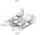
- FIG. 2 is a perspective view illustrating a structure of a conventional power module.
- a power board is connected to a control board through a unidirectional signal pin in the vertical or horizontal direction and is used.
- a bidirectional signal pin module includes: a signal pin configured to electrically connect two objects; and a socket having a bent body shape including bent portions, and configured to fix the signal pin in either one of a horizontal direction and a vertical direction.
- the bent portions of the socket may include holes disposed in the horizontal direction or the vertical direction, and configured to be coupled to the signal pin.
- the signal pin may be configured to be coupled to the socket in a press-fit connection manner.
- a power module in another general aspect, includes: a power board which configured to receive a signal; a control board configured to transmit the signal to the power board; and a bidirectional signal pin module electrically connecting the power board and the control board to each other.
- the control board may have either one of a current control property and a temperature control property.
- the bidirectional signal pin module may include: a signal pin configured to have the signal transmitted or received therethrough; and a socket fixing the signal pin.
- the signal pin may be fixed to the socket in either one of a horizontal direction and a vertical direction.
- the bidirectional signal pin module may connect the power board and the control board to each other in either one of a horizontal direction and a vertical direction.
- the bidirectional signal pin module may be individually designed to connect the control board to the power board.
- the power module may further include: another control board configured to transmit another signal to the power board; and another bidirectional signal pin module electrically connecting the power board and the other control board to each other.
- the bidirectional signal pin module may connect the power board and the control board to each other in a horizontal direction.
- the other bidirectional signal pin module may connect the power board and the other control board to each other in a vertical direction.
- a method of manufacturing a power module includes: preparing a power board configured to receive a signal; preparing a control board configured to transmit the signal to the power board; preparing a bidirectional signal pin module electrically connecting the power board and the control board to each other; and electrically connecting the power board and the control board to each other through the bidirectional signal pin module.
- the preparing of the control board may include preparing the control board to have either one of a current control property and a temperature control property.
- the preparing of the bidirectional signal pin module may include fixing a signal pin, configured to have the signal is transmitted or received therethrough, to a socket.
- the method may further include fixing the signal pin to the socket in either one of a horizontal direction and a vertical direction, through a press-fit process.
- FIGS. 3A and 3B show perspective views illustrating a bidirectional signal pin module 10 according to the present invention.
- the bidirectional signal pin module 10 according to the present invention includes a signal pin 11 and a socket 12.
- the signal pin 11 according to the present invention may electrically connect two different objects.
- the signal pin 11 is a medium, which electrically connects two objects and through which an electrical signal is transmitted, and any one object may transmit a control signal to control another object.
- a control signal of a control board may be transmitted to a power board through the signal pin 11.
- the signal pin 11 may be manufactured by performing a molding process, a machining process, and an injecting process on a conductive metal sheet through which electricity flows.
- the socket 12 according to the present invention may fix the signal pin 11 in any one direction of horizontal and vertical directions.
- the socket 12 may be formed in a bent body shape having bent portions, and the bent portions may be formed in a " ⁇ " shape.
- the socket 12 has a " ⁇ " shape bent by 90°, when any one surface is a vertical surface, the other surface may extend in a horizontal direction.
- a hole 13, into which signal pin 11 is fitted, may be formed in each surface of the socket 12 having the " ⁇ " shape.
- the socket 12 may be coupled to the signal pin 11 in the vertical or horizontal direction.
- the hole 13 is formed in each of the bent portions of the socket 12.
- the signal pin 11 is coupled to the socket 12 in the vertical direction
- the signal pin 11 is coupled to the socket 12 in the horizontal direction.
- the signal pin 11 may be coupled to the socket 12 in a press-fit connection manner.
- an indenter may use a pressure to push and fit the signal pin 11 into the hole 13 of the socket 12 so as to perform cold welding in which a contact surface of the signal pin 11 and a contact surface of the hole 13 are pressed against each other.
- the signal pin 11 since a central portion of the signal pin 11 is formed of a flexible material, when a press-fit process is performed, the signal pin 11 absorbs a force and is deformed due to an elastic property thereof, and thus the deformation of the hole 13 may be minimized.
- the signal pin 11 is pressed against the hole 13 by a minimum pressure, and thus a tight mechanical coupling property may be achieved.
- FIG. 4 is a perspective view illustrating a power module 100 according to the present invention.
- the power module 100 includes bidirectional signal pin modules 10, a power board 20, and control boards 30.
- the power module 100 is a module to which the bidirectional signal pin modules 10 are applied, and the bidirectional signal pin modules 10 may electrically connect the power board 20, which will be described below, and the control boards 30.
- the power board 20 may receive an electrical signal through a switching element.
- the power board 20 is formed as a board on which busbar patterns, through which the electrical signal is received, are formed, and the bidirectional signal pin modules 10 are fitted and soldered to a plurality of holes formed between the busbar patterns.
- the power board 20 receives a signal of the control board 30, which will be described below, through the bidirectional signal pin module 10.
- the control board 30 may transmit a signal to the power board 20.
- the one or more control boards 30 each may have any one of current and temperature control properties.
- control board 30 may be connected to the power board 20 through the bidirectional signal pin module 10 in the horizontal or vertical direction.
- control boards 30 may include two control boards including a current control board and a temperature control board, the current control board may be connected to the bidirectional signal pin module 10 in the horizontal direction, and the temperature control board may be connected to the bidirectional signal pin module 10 in the vertical direction.
- the signal pin 11 may be individually designed, in the power module 100 according to the present invention, customized signal connection may be performed by the bidirectional signal pin module 10 capable of connecting the power board 20 and the control board 30 in the horizontal or vertical direction.
- the plurality of control boards 30 may be connected to one power board 20.
- the power module 100 since an effective layout of components in the power module 100 may designed due to the bidirectional signal pin modules 10, the power module 100 itself may be miniaturized.
- FIG. 5 is a flowchart illustrating a method of manufacturing the power module according to the present invention.
- the method of manufacturing the power module according to the present invention may include four operations (a), (b), (c), and (d).
- the power board 20 may be prepared.
- the busbar pattern capable of receiving an electrical signal through the switching element may be formed on the power board 20.
- one or more control boards 30 may be prepared.
- the one or more control boards 30 may be prepared to each have any one control property of current and temperature control properties.
- one or more bidirectional signal pin modules 10 may be prepared to transmit a control signal of the control board 30 to the power board 20.
- the signal pin 11 may be fixed to the socket 12, through which an electrical signal may be transmitted and received, through a press-fit process.
- the socket 12 may have the " ⁇ " shape having the bent portions and may be prepared in a state in which the hole 13 is formed in each bent surface and coupled to the signal pin 11 in any one direction of the horizontal and vertical directions.
- the power board 20 and the control board 30 may be electrically connected through the bidirectional signal pin module 10.
- bidirectional signal pin module 10 may connect the power board 20 and the control board 30 in any one direction of the horizontal and vertical directions, and the signal pin 11 may be individually designed at the same time, customized signal connection may be performed between the power board 20 and one or more control boards 30.
- control boards 30 may be connected to one power board 20.
- the control boards 30 may be prepared as two control boards including the current control board and the temperature control board, the current control board may be connected to the bidirectional signal pin module 10 in the horizontal direction, and the temperature control board may be connected to the bidirectional signal pin module 10 in the vertical direction.
- the power board 20 and the control boards 30 may be connected by connecting the bidirectional signal pin modules 10, to which the press-fit process is applied, to the power board 20 and the control board 30 without performing a soldering process which is a conventional connection process.
- an effect of miniaturizing a power module can be obtained by applying a bidirectional signal pin socket in a horizontal or vertical direction.
- an effect of customized signal connection of the power module can be obtained by individually designing a signal pin.
- an effect of minimizing an arrangement of components and simplifying a process can be obtained by securing a degree of design freedom for the power module.
Landscapes
- Engineering & Computer Science (AREA)
- Microelectronics & Electronic Packaging (AREA)
- Coupling Device And Connection With Printed Circuit (AREA)
- Multi-Conductor Connections (AREA)
Abstract
Description
- This application claims the benefit of
Korean Patent Application No. 10-2021-0110482, filed on August 20, 2021 - The disclosure herein relates to a bidirectional signal pin module and a power module including the same.
- Particularly, the disclosure herein relates to a technology of inserting a signal pin into a bidirectional, that is, vertical and horizontal, signal pin socket in one of two directions to connect a power board and a control board in order to effectively arrange components of a power module.
- As the market for electrified vehicles, such as hybrid vehicles and electric vehicles, grows, the demand for power converters, which serve to supply and control power, is increasing, and particularly, innovative development of power modules, which are key components, is attracting attention.
- A motor is a main power source of an electrified vehicle, and the motor receives power from a battery so as to drive the vehicle.
- A power converter serves to seamlessly supply power of a battery to a motor and to control the power, and particularly, since the performance of a power module, which is a key component of the power converter, greatly affects power efficiency, innovative development is being conducted in various fields of simplifying a structure, increasing a density, lowering a weight, and improving the performance of the power module.
- The present technology is a technology for developing a high density and high performance product by applying a bidirectional signal pin module of a power module.
- The power module includes a power board, a control board, and a signal pin which electrically connects the power board and the control board.
- The signal pin serves to transmit a signal of the control board to a switching element of the power board.
-
FIG. 1 is a perspective view illustrating a conventional unidirectional signal pin in a vertical direction, andFIG. 2 is a perspective view illustrating a structure of a conventional power module. - Referring to
FIGS. 1 and2 , in the conventional power module, a power board is connected to a control board through a unidirectional signal pin in the vertical or horizontal direction and is used. - However, when the power board and the control board are connected through the unidirectional signal pin, there is a restriction in a layout of components in the power module, and thus inefficiency of a degree of design freedom and space utilization occurs.
- Accordingly, there is a requirement for developing a structure for improving a degree of design freedom and space utilization and simplifying and miniaturizing a structure of a power module.
-
Korean Patent Publication No. 10-2013-0013341 - This Summary is provided to introduce a selection of concepts in a simplified form that are further described below in the Detailed Description. This Summary is not intended to identify key features or essential features of the claimed subject matter, nor is it intended to be used as an aid in determining the scope of the claimed subject matter.
- In one general aspect, a bidirectional signal pin module includes: a signal pin configured to electrically connect two objects; and a socket having a bent body shape including bent portions, and configured to fix the signal pin in either one of a horizontal direction and a vertical direction.
- The bent portions of the socket may include holes disposed in the horizontal direction or the vertical direction, and configured to be coupled to the signal pin.
- The signal pin may be configured to be coupled to the socket in a press-fit connection manner.
- In another general aspect, a power module includes: a power board which configured to receive a signal; a control board configured to transmit the signal to the power board; and a bidirectional signal pin module electrically connecting the power board and the control board to each other.
- The control board may have either one of a current control property and a temperature control property.
- The bidirectional signal pin module may include: a signal pin configured to have the signal transmitted or received therethrough; and a socket fixing the signal pin.
- The signal pin may be fixed to the socket in either one of a horizontal direction and a vertical direction.
- The bidirectional signal pin module may connect the power board and the control board to each other in either one of a horizontal direction and a vertical direction.
- The bidirectional signal pin module may be individually designed to connect the control board to the power board.
- The power module may further include: another control board configured to transmit another signal to the power board; and another bidirectional signal pin module electrically connecting the power board and the other control board to each other.
- The bidirectional signal pin module may connect the power board and the control board to each other in a horizontal direction. The other bidirectional signal pin module may connect the power board and the other control board to each other in a vertical direction.
- In another general aspect, a method of manufacturing a power module includes: preparing a power board configured to receive a signal; preparing a control board configured to transmit the signal to the power board; preparing a bidirectional signal pin module electrically connecting the power board and the control board to each other; and electrically connecting the power board and the control board to each other through the bidirectional signal pin module.
- The preparing of the control board may include preparing the control board to have either one of a current control property and a temperature control property.
- The preparing of the bidirectional signal pin module may include fixing a signal pin, configured to have the signal is transmitted or received therethrough, to a socket.
- The method may further include fixing the signal pin to the socket in either one of a horizontal direction and a vertical direction, through a press-fit process.
- Other features and aspects will be apparent from the following detailed description, the drawings, and the claims.
- The above and other objects, features and advantages of the present invention will become more apparent to those of ordinary skill in the art by describing exemplary embodiments thereof in detail with reference to the accompanying drawings, in which:
-
FIG. 1 is a perspective view illustrating a conventional unidirectional signal pin in a vertical direction; -
FIG. 2 is a perspective view illustrating a structure of a conventional power module; -
FIGS. 3A and 3B show perspective views illustrating a bidirectional signal pin module (10) according to the present invention; -
FIG. 4 is a perspective view illustrating a power module (100) according to the present invention; and -
FIG. 5 is a flowchart illustrating a method of manufacturing the power module according to the present invention. - The present invention will be described in detail with reference to the accompanying drawings. Here, a repeated description and detailed descriptions of known functions and configurations that may unnecessarily obscure the gist of the invention will be omitted. Embodiments of the present invention are provided in order to fully explain the present invention to those skilled in the art. Therefore, shapes and sizes of elements in the drawings may be exaggerated for clearer description.
- Throughout this specification, when a certain part "includes" a certain component, other components are not excluded from being included unless explicitly described otherwise, and other components may further be included or provided.
- Hereinafter, the exemplary embodiments of the invention will be described for promoting an understanding of the present invention. However, the following embodiments should be considered in a descriptive sense only and the scope of the invention is not limited to the following embodiments.
- Hereinafter, a bidirectional signal pin module according to the present invention will be described in detail with reference to the accompanying drawings.
-
FIGS. 3A and 3B show perspective views illustrating a bidirectionalsignal pin module 10 according to the present invention. Referring toFIGS. 3A and 3B , the bidirectionalsignal pin module 10 according to the present invention includes asignal pin 11 and asocket 12. - The
signal pin 11 according to the present invention may electrically connect two different objects. - The
signal pin 11 is a medium, which electrically connects two objects and through which an electrical signal is transmitted, and any one object may transmit a control signal to control another object. For example, in the power module, a control signal of a control board may be transmitted to a power board through thesignal pin 11. - The
signal pin 11 may be manufactured by performing a molding process, a machining process, and an injecting process on a conductive metal sheet through which electricity flows. - The
socket 12 according to the present invention may fix thesignal pin 11 in any one direction of horizontal and vertical directions. - The
socket 12 may be formed in a bent body shape having bent portions, and the bent portions may be formed in a "⊂ " shape. - Since the
socket 12 has a "⊂ " shape bent by 90°, when any one surface is a vertical surface, the other surface may extend in a horizontal direction. - In addition, a
hole 13, into which signalpin 11 is fitted, may be formed in each surface of thesocket 12 having the "⊂ " shape. - Accordingly, the
socket 12 may be coupled to thesignal pin 11 in the vertical or horizontal direction. - Referring to
FIGS. 3A and 3B , it may be seen that thehole 13 is formed in each of the bent portions of thesocket 12. - In addition, referring to
FIG. 3A , it may be seen that thesignal pin 11 is coupled to thesocket 12 in the vertical direction, and referring toFIG. 3B , it may be seen that thesignal pin 11 is coupled to thesocket 12 in the horizontal direction. - In this case, the
signal pin 11 may be coupled to thesocket 12 in a press-fit connection manner. - In the press-fit connection manner, an indenter may use a pressure to push and fit the
signal pin 11 into thehole 13 of thesocket 12 so as to perform cold welding in which a contact surface of thesignal pin 11 and a contact surface of thehole 13 are pressed against each other. - In this case, since a central portion of the
signal pin 11 is formed of a flexible material, when a press-fit process is performed, thesignal pin 11 absorbs a force and is deformed due to an elastic property thereof, and thus the deformation of thehole 13 may be minimized. - In addition, due to the press-fit connection manner, the
signal pin 11 is pressed against thehole 13 by a minimum pressure, and thus a tight mechanical coupling property may be achieved. - Hereinafter, the power module according to the present invention will be described in detail with reference to the accompanying drawings.
-
FIG. 4 is a perspective view illustrating a power module 100 according to the present invention; and - Referring to
FIG. 4 , the power module 100 according to the present invention includes bidirectionalsignal pin modules 10, apower board 20, andcontrol boards 30. - The power module 100 according to the present invention is a module to which the bidirectional
signal pin modules 10 are applied, and the bidirectionalsignal pin modules 10 may electrically connect thepower board 20, which will be described below, and thecontrol boards 30. - The
power board 20 according to the present invention may receive an electrical signal through a switching element. - The
power board 20 is formed as a board on which busbar patterns, through which the electrical signal is received, are formed, and the bidirectionalsignal pin modules 10 are fitted and soldered to a plurality of holes formed between the busbar patterns. - Accordingly, the
power board 20 receives a signal of thecontrol board 30, which will be described below, through the bidirectionalsignal pin module 10. - The
control board 30 according to the present invention may transmit a signal to thepower board 20. - The one or
more control boards 30 each may have any one of current and temperature control properties. - In addition, the
control board 30 may be connected to thepower board 20 through the bidirectionalsignal pin module 10 in the horizontal or vertical direction. - For example, the
control boards 30 may include two control boards including a current control board and a temperature control board, the current control board may be connected to the bidirectionalsignal pin module 10 in the horizontal direction, and the temperature control board may be connected to the bidirectionalsignal pin module 10 in the vertical direction. - Accordingly, since the
signal pin 11 may be individually designed, in the power module 100 according to the present invention, customized signal connection may be performed by the bidirectionalsignal pin module 10 capable of connecting thepower board 20 and thecontrol board 30 in the horizontal or vertical direction. - Accordingly, the plurality of
control boards 30 may be connected to onepower board 20. In addition, since an effective layout of components in the power module 100 may designed due to the bidirectionalsignal pin modules 10, the power module 100 itself may be miniaturized. - Hereinafter, a method of manufacturing the power module according to the present invention will be described with reference to the accompanying drawings.
-
FIG. 5 is a flowchart illustrating a method of manufacturing the power module according to the present invention. Referring toFIG. 5 , the method of manufacturing the power module according to the present invention may include four operations (a), (b), (c), and (d). - In operation (a) according to the present invention, the
power board 20 may be prepared. - The busbar pattern capable of receiving an electrical signal through the switching element may be formed on the
power board 20. - In operation (b) according to the present invention, one or
more control boards 30 may be prepared. - The one or
more control boards 30 may be prepared to each have any one control property of current and temperature control properties. - In operation (c) according to the present invention, one or more bidirectional
signal pin modules 10 may be prepared to transmit a control signal of thecontrol board 30 to thepower board 20. - In the bidirectional
signal pin module 10, thesignal pin 11 may be fixed to thesocket 12, through which an electrical signal may be transmitted and received, through a press-fit process. - The
socket 12 may have the "⊂ " shape having the bent portions and may be prepared in a state in which thehole 13 is formed in each bent surface and coupled to thesignal pin 11 in any one direction of the horizontal and vertical directions. - In operation (d) according to the present invention, the
power board 20 and thecontrol board 30 may be electrically connected through the bidirectionalsignal pin module 10. - Since the bidirectional
signal pin module 10 may connect thepower board 20 and thecontrol board 30 in any one direction of the horizontal and vertical directions, and thesignal pin 11 may be individually designed at the same time, customized signal connection may be performed between thepower board 20 and one ormore control boards 30. - In other words, the plurality of
control boards 30 may be connected to onepower board 20. Accordingly, thecontrol boards 30 may be prepared as two control boards including the current control board and the temperature control board, the current control board may be connected to the bidirectionalsignal pin module 10 in the horizontal direction, and the temperature control board may be connected to the bidirectionalsignal pin module 10 in the vertical direction. - In addition, the
power board 20 and thecontrol boards 30 may be connected by connecting the bidirectionalsignal pin modules 10, to which the press-fit process is applied, to thepower board 20 and thecontrol board 30 without performing a soldering process which is a conventional connection process. - Accordingly, an effect of reducing the number of processes of a manufacturing process of the power module 100 can be obtained.
- According to the present invention, an effect of miniaturizing a power module can be obtained by applying a bidirectional signal pin socket in a horizontal or vertical direction.
- In addition, an effect of customized signal connection of the power module can be obtained by individually designing a signal pin.
- In addition, an effect of minimizing an arrangement of components and simplifying a process can be obtained by securing a degree of design freedom for the power module.
- While the present invention has been described with reference to the exemplary embodiments thereof, it will be understood by those skilled in the art that the present invention may be variously changed and modified without departing from the spirit and scope of the invention defined by the appended claims.
Claims (15)
- A bidirectional signal pin module, comprising:a signal pin configured to electrically connect two objects; anda socket having a bent body shape including bent portions, and configured to fix the signal pin in either one of a horizontal direction and a vertical direction.
- The bidirectional signal pin module of claim 1, wherein the bent portions of the socket include holes disposed in the horizontal direction or the vertical direction, and configured to be coupled to the signal pin.
- The bidirectional signal pin module of claim 1, wherein the signal pin is configured to be coupled to the socket in a press-fit connection manner.
- A power module, comprising:a power board which configured to receive a signal;a control board configured to transmit the signal to the power board; anda bidirectional signal pin module electrically connecting the power board and the control board to each other.
- The power module of claim 4, wherein the control board has either one of a current control property and a temperature control property.
- The power module of claim 4, wherein the bidirectional signal pin module includes:a signal pin configured to have the signal transmitted or received therethrough; anda socket fixing the signal pin.
- The power module of claim 6, wherein the signal pin is fixed to the socket in either one of a horizontal direction and a vertical direction.
- The power module of claim 4, wherein the bidirectional signal pin module connects the power board and the control board to each other in either one of a horizontal direction and a vertical direction.
- The power module of claim 4, wherein the bidirectional signal pin module is individually designed to connect the control board to the power board.
- The power module of claim 4, further comprising:another control board configured to transmit another signal to the power board; andanother bidirectional signal pin module electrically connecting the power board and the other control board to each other.
- The power module of claim 10, wherein the bidirectional signal pin module connects the power board and the control board to each other in a horizontal direction, and
wherein the other bidirectional signal pin module connects the power board and the other control board to each other in a vertical direction. - A method of manufacturing a power module, comprising:preparing a power board configured to receive a signal;preparing a control board configured to transmit the signal to the power board;preparing a bidirectional signal pin module electrically connecting the power board and the control board to each other; andelectrically connecting the power board and the control board to each other through the bidirectional signal pin module.
- The method of claim 12, wherein the preparing of the control board includes preparing the control board to have either one of a current control property and a temperature control property.
- The method of claim 12, wherein the preparing of the bidirectional signal pin module includes fixing a signal pin, configured to have the signal is transmitted or received therethrough, to a socket.
- The method of claim 14, further comprising fixing the signal pin to the socket in either one of a horizontal direction and a vertical direction, through a press-fit process.
Applications Claiming Priority (1)
| Application Number | Priority Date | Filing Date | Title |
|---|---|---|---|
| KR1020210110482A KR102651499B1 (en) | 2021-08-20 | 2021-08-20 | Bidirectional signal pin module, power module including the same and manufacturing method thereof |
Publications (1)
| Publication Number | Publication Date |
|---|---|
| EP4138223A1 true EP4138223A1 (en) | 2023-02-22 |
Family
ID=78957937
Family Applications (1)
| Application Number | Title | Priority Date | Filing Date |
|---|---|---|---|
| EP21215979.2A Pending EP4138223A1 (en) | 2021-08-20 | 2021-12-20 | Bidirectional signal pin module, power module including the same, and method of manufacturing the same |
Country Status (5)
| Country | Link |
|---|---|
| US (1) | US12283764B2 (en) |
| EP (1) | EP4138223A1 (en) |
| JP (1) | JP7459039B2 (en) |
| KR (2) | KR102651499B1 (en) |
| CN (1) | CN115708267A (en) |
Families Citing this family (3)
| Publication number | Priority date | Publication date | Assignee | Title |
|---|---|---|---|---|
| KR102651499B1 (en) * | 2021-08-20 | 2024-03-27 | 현대모비스 주식회사 | Bidirectional signal pin module, power module including the same and manufacturing method thereof |
| DE102022214174A1 (en) | 2022-12-21 | 2024-06-27 | Robert Bosch Gesellschaft mit beschränkter Haftung | Electronic module and contact arrangement |
| WO2025091328A1 (en) * | 2023-11-01 | 2025-05-08 | Nexperia Technology (Shanghai) Ltd. | Signal pin, electronic device, and method of assembling an electronic device |
Citations (4)
| Publication number | Priority date | Publication date | Assignee | Title |
|---|---|---|---|---|
| FR2391574A1 (en) * | 1977-05-20 | 1978-12-15 | Zaklady Radiowe Unitra Eltra | Multiple connector with three rows of holes - admits plug pins in any one of three directions into contacting cavities |
| DE3146491A1 (en) * | 1981-10-09 | 1982-05-06 | Robert Bosch Gmbh, 7000 Stuttgart | Plug device |
| WO2009106581A2 (en) * | 2008-02-28 | 2009-09-03 | Viemme Srl | Improved electrical connection |
| KR20130013341A (en) | 2011-07-28 | 2013-02-06 | 현대모비스 주식회사 | Signal pin module and power control unit using signal pin module |
Family Cites Families (68)
| Publication number | Priority date | Publication date | Assignee | Title |
|---|---|---|---|---|
| US3034084A (en) * | 1958-03-10 | 1962-05-08 | Rodale Mfg Co Inc | Cube tap |
| US3208027A (en) * | 1962-05-08 | 1965-09-21 | Johnson Co E F | Connector for printed circuits |
| US4571014A (en) * | 1984-05-02 | 1986-02-18 | At&T Bell Laboratories | High frequency modular connector |
| US4810215A (en) * | 1985-06-06 | 1989-03-07 | Yazaki Corporation | Position compensating connector |
| US5595513A (en) * | 1990-02-22 | 1997-01-21 | Yazaki Corporation | Bulb socket terminal |
| US5374204A (en) * | 1993-11-30 | 1994-12-20 | The Whitake Corporation | Electrical terminal with compliant pin section |
| US5490787A (en) * | 1994-08-29 | 1996-02-13 | The Whitaker Corporation | Electrical connector with integral supporting structure |
| US5895278A (en) * | 1996-10-10 | 1999-04-20 | Thomas & Betts Corporation | Controlled impedance, high density electrical connector |
| US5823795A (en) * | 1996-10-30 | 1998-10-20 | Hewlett-Packard Company | Connector between a daughterboard and a motherboard for high-speed single-ended electrical signals |
| JPH10289769A (en) | 1997-04-11 | 1998-10-27 | Nec Corp | Electrical connector |
| JP2980055B2 (en) * | 1997-05-06 | 1999-11-22 | ミツミ電機株式会社 | Contact Pin Mounting Method for Horizontal Modular Jack |
| US6227882B1 (en) * | 1997-10-01 | 2001-05-08 | Berg Technology, Inc. | Connector for electrical isolation in a condensed area |
| US6238225B1 (en) * | 1998-09-23 | 2001-05-29 | Tvm Group, Inc. | Bus bar assembly |
| JP3295050B2 (en) * | 1999-02-10 | 2002-06-24 | エスエムケイ株式会社 | CRT socket |
| TW449124U (en) * | 2000-08-16 | 2001-08-01 | Hon Hai Prec Ind Co Ltd | Electrical connector assembly |
| JP3491064B2 (en) * | 2000-10-20 | 2004-01-26 | 日本航空電子工業株式会社 | High-speed transmission connector |
| TW525835U (en) * | 2001-05-24 | 2003-03-21 | Atom Technology Inc | Conductive sheet structure for multi-directional insertion socket |
| US6464542B1 (en) | 2001-07-19 | 2002-10-15 | Hon Hai Precision Ind. Co., Ltd. | Connector assembly having small profile |
| US6830465B2 (en) * | 2001-08-24 | 2004-12-14 | Adc Telecommunications, Inc. | Interconnect chassis and module |
| US6616459B2 (en) * | 2001-08-24 | 2003-09-09 | Adc Telecommunications, Inc. | Card edge contact including compliant end |
| US6848922B2 (en) * | 2003-03-10 | 2005-02-01 | Hypertronics Corporation | Socket contact with integrally formed arc arresting portion |
| US6780059B1 (en) * | 2003-06-26 | 2004-08-24 | Teradyne, Inc. | High speed, high density electrical connector |
| KR100559002B1 (en) * | 2004-06-21 | 2006-03-10 | 현대자동차주식회사 | Hinge assembly structure for improved vehicle door closure |
| US20060046525A1 (en) * | 2004-08-27 | 2006-03-02 | Allan Mark | Printed circuit board type connector using surface mount and through hole technologies |
| KR101013172B1 (en) | 2006-04-28 | 2011-02-10 | 니혼 하츠쵸 가부시키가이샤 | Conductive contact holder |
| JP4752625B2 (en) * | 2006-06-01 | 2011-08-17 | 富士ゼロックス株式会社 | Support stand, scanner device, and image recording device |
| KR100839412B1 (en) * | 2006-11-27 | 2008-06-19 | 삼성에스디아이 주식회사 | Plasma display device |
| DE202009010474U1 (en) * | 2008-12-19 | 2010-04-29 | Weidmüller Interface GmbH & Co. KG | Connecting device for connecting a multi-strand conductor |
| KR20100104800A (en) * | 2009-03-19 | 2010-09-29 | 주식회사 아코세미컨덕터 | Power module device having stand off terminal |
| DE102011005073A1 (en) * | 2011-03-03 | 2012-09-06 | Würth Elektronik Ics Gmbh & Co. Kg | Tandem Multi Fork press-in pin |
| KR20130021570A (en) * | 2011-08-23 | 2013-03-06 | 현대모비스 주식회사 | Wator cooling type invertor |
| US8894442B2 (en) * | 2012-04-26 | 2014-11-25 | Tyco Electronics Corporation | Contact modules for receptacle assemblies |
| US8684768B2 (en) * | 2012-09-05 | 2014-04-01 | Wieson Technologies Co., Ltd. | Digital visual interface dual-stack connector |
| JP6103917B2 (en) * | 2012-12-18 | 2017-03-29 | ヒロセ電機株式会社 | Electrical connector assembly |
| DE102013101823B4 (en) * | 2013-02-25 | 2016-04-28 | Phoenix Contact Gmbh & Co. Kg | Contact carrier with a lower part |
| CN105074919B (en) * | 2013-02-26 | 2018-03-30 | 三菱电机株式会社 | power semiconductor device |
| US11221110B2 (en) * | 2013-03-13 | 2022-01-11 | Smartbotics, Inc. | LED light bulb construction and manufacture |
| DE102013103446A1 (en) * | 2013-04-05 | 2014-10-09 | Phoenix Contact Gmbh & Co. Kg | Connector device |
| TWI515980B (en) * | 2013-07-11 | 2016-01-01 | 正淩精密工業股份有限公司 | Bi-directional data transmission method, high-frequency connector and an optical connector using the same |
| US9306349B2 (en) * | 2014-01-21 | 2016-04-05 | Allocacoc Corporation | Construction of an alternating current (AC) power socket |
| KR101510056B1 (en) * | 2014-05-14 | 2015-04-07 | 현대자동차주식회사 | Hybrid power control apparatus for vehicle |
| JP5871044B1 (en) * | 2014-12-05 | 2016-03-01 | 第一精工株式会社 | Terminal module |
| US10023057B2 (en) * | 2015-04-22 | 2018-07-17 | Cristian A. Sobota Rodriguez | Contactless charger and battery management |
| US10231348B2 (en) * | 2015-05-28 | 2019-03-12 | Yazaki Corporation | Heat dissipation structure for connector module |
| KR102411616B1 (en) | 2015-07-07 | 2022-06-21 | 주식회사 만도 | Integrated moter-inverter assembly |
| CN108028481B (en) * | 2015-07-23 | 2021-08-20 | 安费诺有限公司 | Extender Modules for Modular Connectors |
| LU93039B1 (en) * | 2016-04-22 | 2017-10-27 | Phoenix Contact Gmbh & Co Kg Intellectual Property Licenses & Standards | plug contact |
| US10522945B2 (en) * | 2016-08-22 | 2019-12-31 | Interplex Industries, Inc. | Electrical connector |
| EP3507132B1 (en) * | 2016-10-05 | 2021-05-05 | Voltu Motor, Inc. | Electric vehicle |
| KR101948101B1 (en) * | 2016-11-09 | 2019-02-14 | 현대오트론 주식회사 | Elctronic control device |
| KR101920634B1 (en) | 2017-02-09 | 2018-11-21 | 퀄맥스시험기술 주식회사 | Camera module test socket |
| US10320482B2 (en) * | 2017-03-21 | 2019-06-11 | Optomedia Technology Inc. | Connector module and optical signal processing device connected thereto |
| JP6997951B2 (en) * | 2018-03-26 | 2022-01-18 | 住友電装株式会社 | Board connector |
| US10600578B2 (en) * | 2018-04-26 | 2020-03-24 | Sf Motors, Inc. | Electric vehicle inverter module capacitors |
| US10877232B1 (en) * | 2018-05-02 | 2020-12-29 | Amazon Technologies, Inc. | Connector for multiple cabling arrangements |
| CN208862209U (en) * | 2018-09-26 | 2019-05-14 | 安费诺东亚电子科技(深圳)有限公司 | A kind of connector and its pcb board of application |
| US10530100B1 (en) * | 2018-10-31 | 2020-01-07 | Te Connectivity Corporation | Communication connector for a communication system |
| CN113597658B (en) * | 2019-02-12 | 2025-05-09 | 能源输入输出智能面板股份有限公司 | Integrated power panel |
| US20220121736A1 (en) * | 2019-07-16 | 2022-04-21 | Brandon Iglesias | Smart Equipment Energizer and Method for Using |
| KR102106970B1 (en) * | 2019-11-26 | 2020-05-13 | 쌍용자동차 주식회사 | The power connection apparatus going the high source apparatus of the environment-friendly vehicle |
| JP2021103905A (en) | 2019-12-24 | 2021-07-15 | アイシン・エィ・ダブリュ株式会社 | Circuit arrangement and method for manufacturing the same |
| WO2021154718A1 (en) * | 2020-01-27 | 2021-08-05 | Fci Usa Llc | High speed, high density direct mate orthogonal connector |
| CN115428275B (en) * | 2020-01-27 | 2025-12-30 | 富加宜(美国)有限责任公司 | High-speed connector |
| CN114077020A (en) * | 2020-08-18 | 2022-02-22 | 华为技术有限公司 | Composite module and method for manufacturing the same |
| US20220063527A1 (en) * | 2020-08-27 | 2022-03-03 | Ford Global Technologies, Llc | Electrical transfer device |
| US11276966B1 (en) * | 2020-09-15 | 2022-03-15 | TE CONNECTIVITY SERVIVES GmbH | High density communication system |
| KR102651499B1 (en) * | 2021-08-20 | 2024-03-27 | 현대모비스 주식회사 | Bidirectional signal pin module, power module including the same and manufacturing method thereof |
| CN217336267U (en) * | 2022-03-30 | 2022-08-30 | 上海峰飞航空科技有限公司 | Motor drive power board and motor driver |
-
2021
- 2021-08-20 KR KR1020210110482A patent/KR102651499B1/en active Active
- 2021-12-20 US US17/556,424 patent/US12283764B2/en active Active
- 2021-12-20 EP EP21215979.2A patent/EP4138223A1/en active Pending
- 2021-12-21 JP JP2021207517A patent/JP7459039B2/en active Active
- 2021-12-23 CN CN202111594309.4A patent/CN115708267A/en active Pending
-
2024
- 2024-03-20 KR KR1020240038547A patent/KR102756771B1/en active Active
Patent Citations (4)
| Publication number | Priority date | Publication date | Assignee | Title |
|---|---|---|---|---|
| FR2391574A1 (en) * | 1977-05-20 | 1978-12-15 | Zaklady Radiowe Unitra Eltra | Multiple connector with three rows of holes - admits plug pins in any one of three directions into contacting cavities |
| DE3146491A1 (en) * | 1981-10-09 | 1982-05-06 | Robert Bosch Gmbh, 7000 Stuttgart | Plug device |
| WO2009106581A2 (en) * | 2008-02-28 | 2009-09-03 | Viemme Srl | Improved electrical connection |
| KR20130013341A (en) | 2011-07-28 | 2013-02-06 | 현대모비스 주식회사 | Signal pin module and power control unit using signal pin module |
Also Published As
| Publication number | Publication date |
|---|---|
| KR102651499B1 (en) | 2024-03-27 |
| JP2023029175A (en) | 2023-03-03 |
| KR102756771B1 (en) | 2025-01-21 |
| US12283764B2 (en) | 2025-04-22 |
| JP7459039B2 (en) | 2024-04-01 |
| KR20230028038A (en) | 2023-02-28 |
| US20230057923A1 (en) | 2023-02-23 |
| KR20240039112A (en) | 2024-03-26 |
| CN115708267A (en) | 2023-02-21 |
Similar Documents
| Publication | Publication Date | Title |
|---|---|---|
| US12283764B2 (en) | Bidirectional signal pin module, power module including the same, and method of manufacturing the same | |
| US12074392B2 (en) | FPCB assembly for battery module, its manufacturing method, and battery module including the same | |
| US9941614B2 (en) | Connection structure of connector capable of managing a large electric current | |
| CN112889175A (en) | Battery cell connection for the electrically conductive connection of round battery cells of a motor vehicle battery and method for producing a motor vehicle battery | |
| US7108521B2 (en) | Pressfit terminal and connection structure | |
| JP2013069491A (en) | Battery wiring module | |
| CN101635288B (en) | System with power semiconductor module and connection device | |
| CN115528390A (en) | Battery cell contact system for a battery module and battery module comprising such a battery cell contact system | |
| WO2013039154A1 (en) | Contact terminal | |
| JP2005222924A (en) | Socket connector | |
| US20240032187A1 (en) | High-current element for high-current printed circuit boards | |
| CN114039234A (en) | Floating electric connection conductor structure, floating electric connector and vehicle-mounted electronic device | |
| KR100654814B1 (en) | Substrate Assembly | |
| CN105024191A (en) | Electrical connection unit between two electronic boards | |
| CN210296703U (en) | End connector of hair button plate | |
| US12548926B2 (en) | Electrical connection terminal and battery pack signal acquisition device | |
| US20240356255A1 (en) | Array of compliant connectors for electronic assemblies | |
| JP2014093275A (en) | Battery pack and vehicle | |
| CN113922126A (en) | Rectangular punched jack assembly | |
| CN223584000U (en) | Motor assembly | |
| CN223871734U (en) | Connector assembly | |
| CN222530881U (en) | A convenient pluggable double-layer quick-plug | |
| CN220234468U (en) | Inverter | |
| CN222052108U (en) | A soft-hard combined connection structure and PCB board with application thereof | |
| US20230155327A1 (en) | Electrical connector |
Legal Events
| Date | Code | Title | Description |
|---|---|---|---|
| PUAI | Public reference made under article 153(3) epc to a published international application that has entered the european phase |
Free format text: ORIGINAL CODE: 0009012 |
|
| STAA | Information on the status of an ep patent application or granted ep patent |
Free format text: STATUS: REQUEST FOR EXAMINATION WAS MADE |
|
| 17P | Request for examination filed |
Effective date: 20211220 |
|
| AK | Designated contracting states |
Kind code of ref document: A1 Designated state(s): AL AT BE BG CH CY CZ DE DK EE ES FI FR GB GR HR HU IE IS IT LI LT LU LV MC MK MT NL NO PL PT RO RS SE SI SK SM TR |
|
| RBV | Designated contracting states (corrected) |
Designated state(s): AL AT BE BG CH CY CZ DE DK EE ES FI FR GB GR HR HU IE IS IT LI LT LU LV MC MK MT NL NO PL PT RO RS SE SI SK SM TR |
|
| STAA | Information on the status of an ep patent application or granted ep patent |
Free format text: STATUS: EXAMINATION IS IN PROGRESS |
|
| 17Q | First examination report despatched |
Effective date: 20250318 |