CN112889175A - Battery cell connection for the electrically conductive connection of round battery cells of a motor vehicle battery and method for producing a motor vehicle battery - Google Patents
Battery cell connection for the electrically conductive connection of round battery cells of a motor vehicle battery and method for producing a motor vehicle battery Download PDFInfo
- Publication number
- CN112889175A CN112889175A CN201880098260.3A CN201880098260A CN112889175A CN 112889175 A CN112889175 A CN 112889175A CN 201880098260 A CN201880098260 A CN 201880098260A CN 112889175 A CN112889175 A CN 112889175A
- Authority
- CN
- China
- Prior art keywords
- battery
- cell
- round
- connection
- battery cell
- Prior art date
- Legal status (The legal status is an assumption and is not a legal conclusion. Google has not performed a legal analysis and makes no representation as to the accuracy of the status listed.)
- Pending
Links
Images


Classifications
-
- H—ELECTRICITY
- H01—ELECTRIC ELEMENTS
- H01M—PROCESSES OR MEANS, e.g. BATTERIES, FOR THE DIRECT CONVERSION OF CHEMICAL ENERGY INTO ELECTRICAL ENERGY
- H01M50/00—Constructional details or processes of manufacture of the non-active parts of electrochemical cells other than fuel cells, e.g. hybrid cells
- H01M50/20—Mountings; Secondary casings or frames; Racks, modules or packs; Suspension devices; Shock absorbers; Transport or carrying devices; Holders
- H01M50/204—Racks, modules or packs for multiple batteries or multiple cells
- H01M50/207—Racks, modules or packs for multiple batteries or multiple cells characterised by their shape
- H01M50/213—Racks, modules or packs for multiple batteries or multiple cells characterised by their shape adapted for cells having curved cross-section, e.g. round or elliptic
-
- H—ELECTRICITY
- H01—ELECTRIC ELEMENTS
- H01M—PROCESSES OR MEANS, e.g. BATTERIES, FOR THE DIRECT CONVERSION OF CHEMICAL ENERGY INTO ELECTRICAL ENERGY
- H01M50/00—Constructional details or processes of manufacture of the non-active parts of electrochemical cells other than fuel cells, e.g. hybrid cells
- H01M50/50—Current conducting connections for cells or batteries
- H01M50/502—Interconnectors for connecting terminals of adjacent batteries; Interconnectors for connecting cells outside a battery casing
- H01M50/503—Interconnectors for connecting terminals of adjacent batteries; Interconnectors for connecting cells outside a battery casing characterised by the shape of the interconnectors
-
- H—ELECTRICITY
- H01—ELECTRIC ELEMENTS
- H01M—PROCESSES OR MEANS, e.g. BATTERIES, FOR THE DIRECT CONVERSION OF CHEMICAL ENERGY INTO ELECTRICAL ENERGY
- H01M50/00—Constructional details or processes of manufacture of the non-active parts of electrochemical cells other than fuel cells, e.g. hybrid cells
- H01M50/50—Current conducting connections for cells or batteries
- H01M50/502—Interconnectors for connecting terminals of adjacent batteries; Interconnectors for connecting cells outside a battery casing
- H01M50/509—Interconnectors for connecting terminals of adjacent batteries; Interconnectors for connecting cells outside a battery casing characterised by the type of connection, e.g. mixed connections
-
- H—ELECTRICITY
- H01—ELECTRIC ELEMENTS
- H01M—PROCESSES OR MEANS, e.g. BATTERIES, FOR THE DIRECT CONVERSION OF CHEMICAL ENERGY INTO ELECTRICAL ENERGY
- H01M50/00—Constructional details or processes of manufacture of the non-active parts of electrochemical cells other than fuel cells, e.g. hybrid cells
- H01M50/50—Current conducting connections for cells or batteries
- H01M50/528—Fixed electrical connections, i.e. not intended for disconnection
-
- H—ELECTRICITY
- H01—ELECTRIC ELEMENTS
- H01M—PROCESSES OR MEANS, e.g. BATTERIES, FOR THE DIRECT CONVERSION OF CHEMICAL ENERGY INTO ELECTRICAL ENERGY
- H01M50/00—Constructional details or processes of manufacture of the non-active parts of electrochemical cells other than fuel cells, e.g. hybrid cells
- H01M50/50—Current conducting connections for cells or batteries
- H01M50/543—Terminals
- H01M50/552—Terminals characterised by their shape
- H01M50/559—Terminals adapted for cells having curved cross-section, e.g. round, elliptic or button cells
- H01M50/56—Cup shaped terminals
-
- H—ELECTRICITY
- H01—ELECTRIC ELEMENTS
- H01M—PROCESSES OR MEANS, e.g. BATTERIES, FOR THE DIRECT CONVERSION OF CHEMICAL ENERGY INTO ELECTRICAL ENERGY
- H01M2220/00—Batteries for particular applications
- H01M2220/20—Batteries in motive systems, e.g. vehicle, ship, plane
-
- Y—GENERAL TAGGING OF NEW TECHNOLOGICAL DEVELOPMENTS; GENERAL TAGGING OF CROSS-SECTIONAL TECHNOLOGIES SPANNING OVER SEVERAL SECTIONS OF THE IPC; TECHNICAL SUBJECTS COVERED BY FORMER USPC CROSS-REFERENCE ART COLLECTIONS [XRACs] AND DIGESTS
- Y02—TECHNOLOGIES OR APPLICATIONS FOR MITIGATION OR ADAPTATION AGAINST CLIMATE CHANGE
- Y02E—REDUCTION OF GREENHOUSE GAS [GHG] EMISSIONS, RELATED TO ENERGY GENERATION, TRANSMISSION OR DISTRIBUTION
- Y02E60/00—Enabling technologies; Technologies with a potential or indirect contribution to GHG emissions mitigation
- Y02E60/10—Energy storage using batteries
Landscapes
- Chemical & Material Sciences (AREA)
- Chemical Kinetics & Catalysis (AREA)
- Electrochemistry (AREA)
- General Chemical & Material Sciences (AREA)
- Connection Of Batteries Or Terminals (AREA)
- Battery Mounting, Suspending (AREA)
Abstract
The invention relates to a battery cell connection (16) for the electrically conductive connection of round battery cells (16) of a motor vehicle battery (10), comprising a plurality of electrically conductive contact elements (24) for the end-side connection of two round battery cells (16) connected in series, wherein the contact elements (24) each have a base contact surface (44) for producing a bonded connection to a corresponding battery cover (22) of a round battery cell (16), and a spring arm (26) for producing a force-fit connection to a corresponding battery cup (20) of a round battery cell (16); a plurality of conductively connected connecting webs (28) which connect the contact elements (24) arranged in groups to one another; the contact element (24) and the connecting web (28) are produced from a common stamped and bent part (48). The invention also relates to a method for producing a motor vehicle battery (10).
Description
Technical Field
The invention relates to a cell connection piece for the electrically conductive connection of round cells of a motor vehicle battery and to a production method for a motor vehicle battery. The invention further relates to a battery for a motor vehicle, comprising a plurality of round battery cells, which are connected to one another in an electrically conductive manner by at least one battery cell connection.
Background
In order to be able to provide the required electrical energy in an electrically driven vehicle, whether a hybrid vehicle or a purely electrically driven vehicle, a plurality of individual battery cells are usually connected or interconnected to one another in an electrically conductive manner. The assembly and interconnection of such battery cells can be very costly, among other things. Individual cells are typically connected in different configurations-partially in parallel and partially in series, depending on performance requirements. In order to be able to supply a corresponding voltage to a high-voltage system of an electrically driven vehicle, it is generally unavoidable to connect such battery cells partially in series with one another in order to be able to obtain an operating voltage of, for example, 400 volts or more. In order to increase the capacity, a plurality of battery cells may be connected in parallel. A major challenge in the production of such batteries for motor vehicles is thus the electrical contact between the individual battery cells which is as simple as possible but reliable.
EP 3096372B 1 describes the possibility of a plurality of round battery cells of a battery being in electrically conductive contact with each other. The circular battery cells are connected in a predetermined arrangement by a plastic bottom plate to form a battery module. Furthermore, the parallel plates made of a contact material with high conductivity properties are used for the electrically conductive connection of the round battery cells. For each round cell, one contact spring is welded to the parallel plate. The contact spring plate is connected with the corresponding positive electrode of the corresponding round battery unit in a non-detachable mode through a laser welding process. Each contact spring is shaped such that it provides a receiving unit for another round battery unit located above it by means of a spring arm. The welding of the contact spring to the base plate is particularly costly. Furthermore, precise positioning of the individual contact domes can be difficult.
Disclosure of Invention
The object of the present invention is to provide a solution by means of which a large number of round battery cells for a battery of a motor vehicle can be connected in an electrically conductive manner in a particularly simple and reliable manner.
This object is achieved by a battery cell connection having an electrically conductive connection for round battery cells and by a method for producing a motor vehicle battery having the features of the independent claims. Targeted and unobvious improvements of the invention are given in the dependent claims.
The cell connection piece for the electrically conductive connection of round battery cells of a motor vehicle battery according to the invention comprises a plurality of electrically conductive connecting contact elements for the end-side connection of two round battery cells connected in series, wherein the contact elements each have a bottom contact surface for producing a material-bonded connection with a corresponding battery cover of a round battery cell and a plurality of spring arms for producing a force-fit connection with a corresponding battery cup of a round battery cell. The battery cover may be the positive electrode corresponding to the circular battery cell and the battery cup may be the negative electrode corresponding to the circular battery cell. However, it is also possible that the battery cover is the respective negative pole of the round battery cell and the battery cup is the respective positive pole of the round battery cell, although this is not usual per se. The cell connecting element according to the invention furthermore has a plurality of conductively connected connecting webs which connect the contact elements arranged in groups to one another. The contact element and the connecting lug are thus produced from a common stamped and bent part. For example, the contact elements and the connecting pieces may be made from a single piece of sheet metal. The cell connection according to the invention does not have to be produced in a cost-effective manner by welding the contact elements and the connecting tabs. Since the contact element and the connecting piece are produced from one common stamped and bent part, the entire cell connecting piece can be produced in large quantities in a particularly simple and cost-effective manner.
In order to connect a respective pair of circular battery cells in series with one another, it is only necessary to join the bottom contact face of one contact element with the respective cell cover material of the circular battery cell, for example by laser welding or the like. Subsequently, another round battery unit with a battery cup can be easily inserted between the spring arms, whereby the battery cup of the round battery unit, for example also the negative pole of the round battery unit, is held in force-fitting engagement between the two spring arms. In this way, individual round battery cells can be very easily connected in pairs in series or in series with one another by means of battery cell connections. Furthermore, a plurality of round battery cells arranged next to one another can be connected in parallel or conductively to one another very easily and with a more reliable process by means of conductive connecting webs which connect the series-connected contact elements in turn conductively to one another. The common stamped and bent part, from which the contact elements and the connecting piece are produced, is preferably stamped out of a material having good electrical conductivity properties and is shaped accordingly in order to form the individual contact elements. The material of the stamped and bent part is thus preferably selected such that it meets not only the requirements for good electrical conductivity but also the requirements for mechanical properties, in particular the requirements for high tensile strength and low thermal stress relaxation.
By means of the cell connection piece according to the invention, a large number of round cells of a motor vehicle battery can be contacted in series and in parallel with one another in a particularly simple and reliable manner. Since the stamped and bent parts for producing the contact elements and the connecting tabs preferably consist of a single sheet of metal, the cell connecting piece can be handled particularly easily during the assembly of the battery, in particular when the individual round cells are in contact. Furthermore, an arrangement with precise positioning of the contact elements relative to one another can be provided automatically.
One embodiment of the invention provides that the voltage taps for equalizing the individual round battery cells are formed on externally arranged contact elements. The voltage taps may, for example, be designed in the form of contact tabs or the like, so that during operation of the battery, the voltage taps can easily be strapped over the parallel-connected round battery cells for battery equalization. In order to achieve the equalization, it is generally necessary to monitor the voltage of each round cell or the voltage of each parallel-connected cell group. In order not to monitor each round battery cell of the battery cell stack individually, the round battery cells connected in parallel are monitored with each other by means of voltage taps.
In a further embodiment of the invention, the spring arm has at least one rib. The total current flow of the respective round battery cells is via the finger-like spring arms, so that the material thereof should have good conductivity, for example, made of copper or similar materials. Thus, in order to obtain a low resistance, the volume of the resilient arm should be as large as possible. The spring force of the individual spring arms should be very high in order to minimize the contact resistance or the transition resistance. This latter requirement is particularly advantageous if the resilient arm is made of spring steel. If the stress relaxation is large, the contact member loses its contact pressure with the lapse of time, and thus the resistance increases. In this case, the contact element is thermally damaged due to the elevated load. The combination of the current and the sum of the resistances leads to power losses which, on the one hand, cannot be used any longer for driving the motor vehicle concerned and, on the other hand, are converted into thermal energy which must be additionally dissipated. A particularly large current per round cell flows through the above-mentioned supercharged battery. The number, volume and electrical conductivity of the spring arms of the contact element must be maximized while the contact resistance should be minimized. For example, copper is a conductor with very good electrical conductivity. However, it has a relatively low tensile strength and a high stress relaxation. By increasing the spring force by additional shaping of the material in the region of the spring arms, a sufficient contact pressure of the spring arms can be achieved. This effect can be achieved particularly easily and reliably by said reinforcement ribs in the spring arms. These ribs are preferably designed to extend from the contact surface of the base into the resilient arms. Thereby increasing the bending stiffness of the resilient arm and, at the same time, increasing the resilience of the resilient arm; a permanent and reliable electrical contact between the spring arms of the contact element and the corresponding battery cups of the round battery cell can thereby be ensured.
According to a further embodiment of the invention, it is provided that the spring arm has at least one longitudinal slot in order to facilitate a planar engagement on the corresponding housing surface of the cell cup of the round cell unit. Depending on the geometry and dimensions, the spring arm can also have a plurality of such longitudinal slots, so that the spring arm is divided into individual segments which can in turn engage particularly well over the corresponding housing surface of the cell cup of the round cell. As a result, the respective transition resistance between the spring arms of the contact element and the respective round battery cell can be reduced.
In a further embodiment of the invention, the bottom contact surface of the contact element is designed to be convex. In this case, the projection is a projection of the bottom contact surface opposite to the direction of extension of the spring arm. By means of these convexly designed bottom contact surfaces, the contact elements can be connected to the corresponding cell covers of the round cell particularly easily and reliably in a material-bonded manner (for example by laser welding or the like). Furthermore, a certain spatial insulation distance between the bottom contact surface and the spring arm, which can be used for fastening a corresponding battery cup, is thereby formed.
Another embodiment of the invention provides that the respective spring ring, preferably made of spring steel, grips the spring arms of the respective contact element on the outer circumferential side. The contact element itself, in particular the spring arm, can therefore be made of a material which has a particularly good electrical conductivity, for example copper. However, a sufficient spring force and thus a sufficiently good force-applying engagement connection between the respective cell cup of the round cell unit and the contact element can be ensured by the spring ring which grips the spring arm of the respective contact element on the outer circumferential side.
According to a further embodiment of the invention, it is provided that the stamped and bent part is produced from a first metal sheet and a second metal sheet which are arranged one above the other and are connected to one another, wherein the first metal sheet has better electrical conductivity than the second metal sheet, and the second metal sheet has a higher spring stiffness than the first metal sheet and in particular also has a lower stress relaxation. By stamping such a hybrid construction of the bent part, not only the mechanical requirements but also the electrical conductivity requirements are taken into account sufficiently. Two metal sheets made of different materials can be made, for example, by cold rolling. By means of such a hybrid construction of the stamped and bent parts, on the one hand the electrical conductivity of the contact element can be maximized and, on the other hand, a permanently applicable force-applying engagement connection between the contact element and the round battery cell can be ensured.
In a further embodiment of the invention, the contact elements are arranged in rows and columns with respect to one another, and each directly adjacent contact element is connected to one another by a connecting web. Some traction batteries for electrically driven vehicles particularly require a large capacity. For this purpose, a plurality of circular battery cells of each battery module are usually connected in parallel or conductively with each other. Since the cell connection element can have contact elements arranged in a plurality of rows and columns relative to one another, a large number of round battery cells can be connected not only in series but also in parallel to one another in a simple manner by means of such an embodiment of the cell connection element, in order in particular to provide a battery having a very high capacity. For batteries with a larger capacity, the applied round battery cells generally have a high capacity, however a low current. In this case, the contact resistance and the specific resistance play a secondary role. In this case, a smaller number of spring arms, for example only three spring arms, may be provided for each contact element. The described stamped and bent parts for producing the contact elements and the connecting webs can thus be produced in a particularly simple manner, for example from a single continuous sheet.
According to a further embodiment of the invention, the connecting lugs have corresponding reinforcing ribs to compensate for mechanical stresses. Due to temperature fluctuations and different material coefficients inside the battery, the respective materials themselves may expand to different degrees. This can lead to stresses and in some cases to fatigue fractures or similar fractures, in particular at the respective material bond connections between the contact elements of the round battery cell and the battery cover. In order to prevent this, provision is preferably made for the reinforcing ribs to be provided on the connecting webs in order to compensate for mechanical stresses. In particular, the mechanical stresses that may occur can thus be compensated for in all spatial directions. Thereby, a permanent and reliable electrical or electrically conductive connection of the individual round battery cells within the battery can be ensured.
The battery according to the invention for a motor vehicle comprises a plurality of round battery cells which are electrically conductively connected to one another by at least one battery cell connection according to the invention or at least one advantageous embodiment of a battery cell connection according to the invention.
One embodiment of the battery provides that the battery comprises a plurality of battery modules arranged one behind the other, each having a module housing with a respective through-opening surrounding a round battery cell, wherein in each case at least one battery cell connection element is arranged between respective opposite end faces of the module housing, by means of which the round battery cells arranged in the respective module housing are electrically conductively connected to one another. In this way, the individual battery modules can be assembled into a battery particularly easily. Thus, the cell connectors are used as electrically conductive interfaces between the respective battery modules, and also between the respective battery cells of the respective battery modules, and also as electrical connection points or interfaces within the battery modules.
In a further embodiment of the battery, the module housings each have an insulating body with a recess for a corresponding battery cover of the round battery cell, on which insulating body the battery cell connection element is arranged and which is connected to the battery cover of the round battery cell retracted into the insulating body by means of a contact surface projecting from the bottom of the battery cell connection element. If the individual battery modules are not nested completely correctly during the production process or, for example, individual spring arms of the contact elements are bent, short-circuiting of one or more circular battery cells may result. Such a short circuit may cause thermal runaway, thereby affecting adjacent battery cells. The insulator is therefore preferably provided, which is arranged between the respective cell cup, for example the negative electrode, of the circular cell unit and the respective contact element. The insulator itself may be a plastic disk or orifice plate. The module housing itself thus preferably comprises said insulating body, which does not have to be mounted in a cost-effective manner inside the battery. Another advantage of a module housing comprising corresponding insulators is that the round battery cells can be positioned optimally in the longitudinal direction and without tolerances from each other. Preferably, the insulator recess has a smaller diameter than the circular battery cell, so that an axial stop is automatically provided for the respective circular battery cell by the recess.
In a method for producing a motor vehicle battery, a plurality of round battery cells are electrically conductively connected to one another at least by means of one battery cell connection according to the invention or by means of an embodiment of a battery cell connection according to the invention.
One embodiment of the method provides that the battery is assembled from a plurality of battery modules. The battery modules are produced in that each battery module is formed by a plurality of round battery cells arranged in corresponding through-openings of a corresponding module housing, and in that the corresponding cell covers of the round battery cells of each module housing are connected in a materially bonded manner to at least one battery cell connecting element. First, the bottom contact surfaces of the counter-contact elements are connected with the respective cell covers of the round cell units, for example by laser welding. Therefore, the circular battery cells must be fixed to each other at correct positions. This can be achieved, for example, by means of a workpiece carrier or the like, but preferably by means of the respective module housing itself, which has said through-opening for enclosing the round battery cell. The round battery unit is therefore first placed into the through-opening of the respective module housing and positioned before the respective battery cover of the round battery unit is connected in a material-bonded manner with the contact element. Another advantage is that the module housing itself can also be used as a transport container for round battery cells from the battery cell manufacturer to the battery manufacturer. Suitable means on the module housing preferably fix the cell connecting pieces in their respective defined positions, whereby the connection of the respective contact element to the respective cell cover of the round cell is significantly simplified and can be realized mechanically.
Finally, a further embodiment of the method provides for the manufactured battery modules to be plugged one behind the other, wherein the respective battery cups of the round battery cells are plugged between the respective spring arms of the contact elements on the battery cell connection arranged on the adjacent battery module. After the round battery cells have been inserted into the respective module housing and the bottom contact surfaces of the contact elements have been welded to the cell covers of the round battery cells, the respective cell cups of the round battery cells, i.e. the cup bottoms of the respective next round battery cells, are plugged between the spring arms of the respective contact elements. For this working step, the respective circular battery cells must also be fixed. This can again be achieved by the workpiece carrier, however, preferably by a corresponding module housing in which the circular battery cells are already arranged fixedly. In principle, it is also possible to insert two complete battery modules into one another. To produce a battery, a plurality of battery modules can also be plugged together in succession. Compensation of length tolerances between the individual round battery cells can thus also be achieved by means of corresponding contact elements.
Further advantages, features and details of the invention can be taken from the following description of preferred embodiments and with reference to the drawings. The features and combinations of features mentioned above in the description, and the features and combinations of features mentioned in the description of the figures and/or shown in the figures alone, can be used not only in the respectively specified combination but also in other combinations or alone without departing from the scope of the invention.
Drawings
Is described with reference to the accompanying drawings, in which
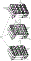
Fig. 1 is a perspective view showing a part of a battery for a motor vehicle, the battery having a plurality of battery modules nested into each other, each battery module having a plurality of circular battery cells;
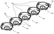
FIG. 2 is a perspective view showing three round battery cells connected by battery cell connectors;
fig. 3 is a perspective view showing a circular battery cell;
FIG. 4 is a perspective view illustrating a cell connector mounted in a battery, the cell connector having a plurality of conductive contact elements connected to each other by respective conductive tabs;
fig. 5 is a perspective view showing a plurality of circular battery cells, in which three pairs of circular battery cells are connected in series with each other at end sides by one battery cell connection member;
fig. 6 is a view showing a series of steps for manufacturing a single battery module;
fig. 7 is a perspective view showing two battery modules before being plugged into each other;
FIG. 8 is a perspective detail view showing one battery module before cell connectors are attached to the battery module;
FIG. 9 is another perspective detail view showing one battery module after the cell connectors have been attached to the battery module;
FIG. 10 is a perspective view illustrating another embodiment of a battery cell connector having a plurality of spring rings per contact element;
FIG. 11 is a top view illustrating another embodiment of a battery cell connector;
FIG. 12 is a sectional view illustrating another embodiment of a battery cell connector taken along section A-A shown in FIG. 11;
FIG. 13 is a perspective view showing a partially finished stamped flexure from which contact elements and connecting tabs are formed; and
fig. 14 is a perspective view illustrating another embodiment of a battery cell connector made of the stamped and bent piece shown in fig. 13.
In the figures, identical or functionally identical elements have identical reference numerals.
Detailed Description
As shown in fig. 1, a battery 10 for a motor vehicle is partially shown in a perspective view. The battery 10 itself may be, for example, a high-voltage battery for electrically driving a vehicle. The battery 10 is made up of a plurality of battery modules 12 nested into mating engagement with one another. Each battery module 12 includes a respective module housing 14, and the module housings 14 are designed to be nestably inserted into one another.
Each battery module 12 has a large number of circular battery cells 16, and for clarity, only some of the circular cell cells 16 are provided with reference numerals. The above example shows each battery module 12 having eight stacked circular battery cells; the cell stacks, which are not labeled in detail, each have five circular cells 16, respectively. Corresponding cell connectors 18 are used for the cross-module and conductive connections of the individual circular cells 16. By means of the cell connection 18, the respective cell cup (the respective negative pole 20 of the round cell 16) and the cell cover (the respective positive pole 22 of the round cell 16) can be connected to each other in an electrically conductive manner across the module. Even though it is assumed throughout the following that the cell cover is the positive electrode 22 and the cell cup is the negative electrode 20, the following description applies equally to the opposite case, i.e. when the positive and negative electrodes are reversed.
As shown in fig. 2, three round battery cells 16 are shown in perspective view, which are connected or in contact with each other in parallel by means of battery cell connections 18. The cell connectors 18, as well as the other cell connectors 18 of the battery 10, have conductively connected contact elements 24, which contact elements 24 serve for the paired end-side connection of two circular battery cells 16 connected in series. Furthermore, the contact element 24 has a corresponding bottom contact surface, which is not shown in greater detail here, for establishing a material-bound connection with the corresponding positive pole 22 of the round cell 16. Furthermore, in the case shown, the contact elements 24 each have four spring arms 26 for establishing a force-fit connection with the corresponding negative pole 20 of the round cell 16, i.e. the cell cup in question. For the sake of clarity, the respective spring arm 26 has reference numerals only on the leftmost contact element 24. Furthermore, the cell connection 18 has a plurality of electrically conductive connecting webs 28, which connect the contact elements 24 arranged in rows to one another. The connecting tabs 28 ensure the parallel connection of the respective circular cells 16. The contact element 24 and the connecting lug 28 are thus produced from a common stamped and bent part.
In fig. 3, one circular battery cell 16 is shown in a perspective view. In this figure, the positive pole 22 of the round cell 16 can be clearly seen, which can be connected in a material-bonded manner, for example by laser welding or the like, to the bottom contact surface 24 of the contact element.
As shown in fig. 4, a battery cell connector 18 is shown in isolation in another perspective view. In the present illustration, the corresponding hole 30 is visible in the region of the bottom contact surface of the contact element 24, which is not shown in greater detail here. These holes 30 may facilitate a material-bonded connection between the contact element 24 and the positive electrode 22 of the round battery cell 16 and also reduce the weight of the battery cell connection 18 by a material-saving method.
On the contact element 24 arranged on the outside, according to the present illustration the contact element 24 arranged on the far left, a voltage tap 32 is provided for equalizing the round battery cells 16 connected in parallel by the battery cell connection 18. To achieve equalization, it is necessary to monitor the voltage of the circular battery cell 16 for each battery cell connection, or to monitor the voltage of each cell group connected in parallel to the circular battery cell 16. By means of the voltage tap 32, there is no need to individually monitor the voltage of the circular battery cells 16 connected in parallel via the battery cell connection 18.
In fig. 5, eight circular battery cells 16 are shown in a perspective view, which have been connected to one another in an electrically conductive manner by means of battery cell connections 18. In this figure, three pairs of circular battery cells 16 are electrically conductively connected to one another on the end sides by contact elements 24. The positive pole 22 of a round cell 16 and the corresponding negative pole 20 of another round cell 16 are thereby electrically conductively connected to one another via the contact element 24. Thereby, the respective elastic arm 26 is connected in forced engagement with the respective negative electrode 20 of the associated circular battery cell 16. The round battery cell 16 must therefore be pressed with its battery bottom, i.e. with its negative pole 20, between the respective spring arms 26 of the contact element 24. The spring arms 26 thereby expand slightly outward and then enclose the round cell 16 in the region of the negative electrode 20 in a force-fit connection, so that a reliable electrical contact can be ensured.
One battery module 12 is shown three times in fig. 6 to further illustrate the various steps for manufacturing the battery module 12. For each circular battery cell 16 to be accommodated, the module housing 14 of the battery module 12 has a corresponding cylindrical through hole 34, which can receive and enclose the circular battery cell 16. As already mentioned, the battery module 12 has eight circular battery cells 16 stacked in five rows. Here, the circular battery cells 16 alternate in rows, with the positive electrodes 22 of the circular battery cells facing forward in one row and the negative electrodes 20 of the circular battery cells facing forward in one row. In this way, the respective module housing 14 is equipped with the respective circular battery cells 16. For each battery row, the module housing 14 also has a corresponding insulator 36, wherein they are also alternately arranged in the front or rear of the module housing 14 as part of the module housing 14, depending on the arrangement of the round battery cells 16. The arrangement of the individual battery connectors 18 corresponds to an alternating arrangement of the circular battery cells 16 in rows, the negative poles 20 and the positive poles 22 of which can be directed forwards or backwards.
After the individual round battery cells 16 are arranged in the module housing 14 (more precisely in the through-openings 34), the individual positive electrodes 22 can be connected to the battery cell connection 18 in a material-bonded manner, for example by laser welding. Since the circular battery cells 16 are arranged within the through-holes 34, they are reliably and positionally accurately fixed. In addition, other means can also be provided on the module housing 14 in order to fix the round battery cells 16 in a positionally precise manner during the welding process, so that the connection of the contact elements 24 of the respective cell connection 18 to the positive pole 22 is facilitated and can be implemented mechanically.
After the individual round battery cells 16 have been inserted into the module housing 14 and the contact elements 24 have been welded to the positive poles 22, the individual battery modules 12 can be inserted into one another. Fig. 7 illustrates this process using two perspective views and shows a battery module 12 equipped with round battery cells 16. Two battery modules 12 equipped with round battery cells 16, which have been materially connected with respective battery cell connections 18 by their respective positive electrodes 22, are easily plugged together. The respective negative pole 20 of the round battery cell 16 is thereby plugged between the respective spring arms 26 of the contact elements 24 of the respective battery cell connector 18, which is arranged on the respectively adjacent battery module 12. The spring arms 26 are thereby bent slightly radially outward and grip the corresponding negative pole 20 of the round cell 16, so that an electrical contact can be ensured. The battery 10 shown in fig. 1 may then be manufactured or assembled by plugging together a plurality of pre-assembled battery modules 12.
Fig. 8 shows the battery module 12 in a perspective detail view before the individual cell connections 18 have not yet been attached. If the battery modules 12 are not inserted into one another exactly or, for example, one spring arm 26 of the cell connection 18 is bent, a short circuit between the individual round cells 16 may result. Such a short circuit may lead to thermal runaway, which may affect the adjacent cells concerned. To avoid this, the insulator 36 is provided as part of the module housing 14. The respective module housing 14 has an insulator 36 per row of cells. The insulator 36 thus has a respective recess 38 for the respective positive pole 22 of the round battery cell 16. Thereby, the respective positive electrodes 22 are arranged to be retracted into the insulators 36, and the positive electrodes 22 do not protrude out of the respective insulators 36 in the axial direction. The insulator may be a plastic disc or an orifice plate. Another advantage of the insulator 36 provided with the recesses 38 is that, since the diameter of the recesses 38 is smaller than the outer diameter of the circular battery cells 16, the individual circular battery cells 16 can be positioned optimally and without tolerances in the longitudinal direction.
Fig. 9 shows the battery module 12 in a further perspective detail, with the battery cell connection 18 now attached. The battery cell connecting element 18 is thereby connected with its convex bottom contact surface, not shown in detail here, to the positive pole 22 of the round battery cell 16, which is retracted into the insulating body. By providing the insulator 36 and the corresponding retracted arrangement of the positive poles 22 of the circular battery cells 16, short circuits between the individual circular battery cells 16 can be effectively avoided during plugging together of the battery modules 12.
Fig. 10 shows a further possible embodiment of a battery cell connection 18 in a perspective view. The cell connection element 18 shown here differs from the cell connection element 18 shown above only in that the respective spring ring 40 grips the spring arms 26 of the respective contact element 24 on the outer circumferential side. Thereby, when the force-applying engagement connection is established with the respective negative electrodes 20 of the circular battery cells 16, an additionally enhanced elastic force can be ensured. The spring ring 40 ensures a permanently reliable force-applying engagement connection with the respective negative pole 20 of the round cell 16, even if the spring arm 26 exhibits an unfavorable relaxation behavior. In this case, the cell connection element 18 may even be made of copper, for example, which, although having very good electrical conductivity, has relatively disadvantageous mechanical properties. The latter can be compensated for by the spring ring 40 which grips the respective spring arm 26 on the outer circumferential side. The spring ring 40 preferably exerts a certain prestress on the respective spring arm 26.
Fig. 11 shows an embodiment of the battery cell connection 18 shown in fig. 10 in a top view. It can again be clearly seen how the respective spring ring 40 grips the four spring arms 26 of the contact element 24 on the outer circumferential side.
Fig. 12 shows the cell connection 18 in a partial sectional view along the section a-a shown in fig. 11. Here again, it can be clearly seen how the spring ring 40 surrounds and grips the spring arms 26 on the outer circumferential side. The spring arms 26 have corresponding recesses 42 into which the spring rings 40 are snapped. To attach or mount the spring ring 40, the spring arms 26 are simply bent radially inward, and the spring ring 40 is then slipped over the spring arms 26 and placed in the region of the recess 42. The spring arms 26 can then be pressed radially outward, so that the respective spring ring 40 is positionally fixed precisely on the recess 42.
In the present illustration, it is also possible to see for the first time the bottom contact surface 44, which has already been mentioned several times, which serves to establish a material-bonded connection with the respective positive pole 22 of the round cell 16. For each contact element 24, all cell connections 18 have this bottom contact surface 44. It can be seen that the bottom contact surface 44 is designed convexly. This means that the respective bottom contact surface 44 is rolled outwards opposite to the direction of extension of the spring arm 26. This facilitates the material-bonded connection of the bottom contact surface 44 to the respective positive pole 22 of the round cell 16.
In order to improve the mechanical properties of the spring arms 26, all embodiments of the battery unit connecting element 18 preferably have at least one reinforcement rib 46 per spring arm 26. These ribs 46 are particularly suitable for radially stiffening the resilient arms 26, i.e. when they are splayed radially outwards by the corresponding circular battery cell 16. The spring force of the individual spring arms 26 should be as large as possible in order to minimize the contact resistance or transition resistance. In addition, these ribs 46 counteract the stress relaxation of the spring arms 26.
Fig. 13 shows the stamped bent part 48, which has not yet been produced, from which the individual contact elements 24 and connecting webs 28 can be produced. The stamped and bent part 4 can be stamped, for example, from a single sheet metal piece, wherein the respective spring arm 26 and the corresponding connecting piece 28 of the contact element 24 are constructed. After the stamping process, the spring arms 26 are bent upwards, and the corresponding raised bottom contact surfaces 44 can also be produced, for example, by a stamping process or other shaping process.
Fig. 14 shows a perspective view of a further embodiment of a cell connection element 18, which is produced from the stamped and bent part 48 shown in fig. 13, which has not yet been produced. In contrast to the battery cell connection 18 shown so far, the battery cell connection 18 comprises not only a single row of contact elements 24. Furthermore, the contact elements 24 are arranged in a plurality of rows and columns with respect to one another, wherein the contact elements 24 arranged directly next to one another are connected to one another by means of corresponding webs 28. In this case, however, the web 28 can also have reinforcing ribs, which are not shown in detail here in the case of the other embodiments, in order to compensate for mechanical stresses.
The cell connection 18 shown here is particularly suitable for large-capacity batteries, in which a large number of round cells 16 in each battery module 12 are connected in parallel to one another. The battery 10 having a large capacity is generally composed of high-capacity battery cells, in the present case, corresponding circular battery cells 16, each circular battery cell 16 having a considerably low current. In this case, the contact resistance and the specific resistance play a rather small role. In this case, it is sufficient for each contact element 24 to have a smaller number of spring arms 26, where the contact element 24 has only three spring arms 26 instead of four. Thus, only three spring arms per contact element 24 need to be provided, which can also be produced relatively simply from a continuous sheet metal material by a press-bending process in the embodiment of the cell connection 18.
List of reference numerals
10 cell
12 cell module
14 Module housing
16-round battery unit
18 cell connector
20 negative electrode of circular battery unit
22 positive electrode of circular battery unit
24 contact element of battery cell connector
26 spring arm of contact element
Connecting piece of 28 battery unit connecting piece
30 holes in contact elements
Voltage tap for 32 cell connection
34 through-hole in module housing
36 insulating body of module casing
38 notches in the insulator
40 spring ring
42 recess of resilient arm
44 bottom contact surface of contact element
46 reinforcing rib of elastic arm
48 stamped bent piece
Claims (15)
1. A battery cell connection (100) for the electrically conductive connection of round battery cells (16) of a motor vehicle battery (10), comprising:
-a plurality of electrically conductively connected contact elements (24) for the end-side connection of each two circular battery cells (16) connected in series, wherein each contact element (24) has a bottom contact surface (44) for producing a material-bonding connection with a corresponding battery cover (22) of the circular battery cell and a plurality of spring arms (26) for producing a force-fit connection with a corresponding battery cup (20) of the circular battery cell (16);
-a plurality of conductively connected connection pads (28) which connect the contact elements (24) arranged in groups to one another;
the method is characterized in that:
the contact element (24) and the connecting web (28) are produced from a common stamped and bent part (48).
2. The battery cell connection (18) according to claim 1,
the method is characterized in that:
a voltage tap (32) for equalizing the round battery cells (16) is formed on one of the externally arranged contact elements (24).
3. The battery cell connection (18) according to claim 1 or 2,
the method is characterized in that:
the spring arms (26) each have at least one rib (46).
4. The battery cell connection (18) according to one of the preceding claims,
the method is characterized in that:
the spring arm (26) has at least one longitudinal slot for the planar engagement on a corresponding housing surface of a cell cup (20) of a round cell unit (16).
5. The battery cell connection (18) according to one of the preceding claims,
the method is characterized in that:
the bottom contact surface (44) of the contact element (24) is designed to be convex.
6. The battery cell connection (18) according to one of the preceding claims,
the method is characterized in that:
the respective spring ring (40) grips the spring arm (26) of the respective contact element (24) on the outer circumference side.
7. The battery cell connection (18) according to one of the preceding claims,
the method is characterized in that:
the stamped and bent part (48) is made of a first metal sheet and a second metal sheet which are arranged one above the other and are connected to one another, wherein the first metal sheet has a better electrical conductivity than the second metal sheet, and the second metal sheet has a higher elastic stiffness than the first metal sheet, and in particular also a lower stress relaxation than the first metal sheet.
8. The battery cell connection (18) according to one of the preceding claims,
the method is characterized in that:
the contact elements (24) are arranged in a plurality of rows and columns with respect to one another, and the directly adjacent contact elements (24) are each connected to one another by a web (28).
9. The battery cell connection (18) according to one of the preceding claims,
the method is characterized in that:
the connecting pieces (28) have corresponding ribs for compensating mechanical stresses.
10. A battery (10) for a motor vehicle, comprising a plurality of round battery cells (16) which are electrically conductively connected to one another by means of at least one battery cell connection (18) according to one of the preceding claims.
11. The battery (10) according to claim 10,
the method is characterized in that:
the battery (10) comprises a plurality of battery modules (12) arranged one behind the other, each having a module housing (14) having a respective through-opening (34) surrounding a round battery cell (16), wherein at least one battery cell connection (18) is arranged between respective opposite end faces of the module housings (14), by means of which the round battery cells (16) arranged in the respective module housings (14) are electrically conductively connected to one another.
12. The battery (10) according to claim 10,
the method is characterized in that:
the module housings (14) each have an insulating body with a recess (38) for a corresponding cell cover of the round cell (16), on which insulating body the cell connecting element (18) is arranged and which is connected by a bottom-protruding contact surface (44) of the cell connecting element to the cell cover (22) of the round cell (16) arranged retracted into the insulating body (36).
13. A method for producing a battery (10) for a motor vehicle, wherein a plurality of round battery cells (16) are connected to one another in an electrically conductive manner by means of at least one battery cell connection (18) according to one of claims 1 to 9.
14. The method of claim 13, wherein the first and second light sources are selected from the group consisting of,
the method is characterized in that:
the battery (10) is composed of a plurality of battery modules (12),
the battery modules (12) are produced in such a way that each battery module (12) is formed by a plurality of round battery cells (16) arranged in corresponding through-openings (34) of a corresponding module housing (14), and the corresponding cell covers (22) of the round battery cells (16) are connected to at least one cell connection element (18) for each module housing (14) in a materially bonded manner.
15. The method of claim 14, wherein the first and second light sources are selected from the group consisting of,
the method is characterized in that:
the produced battery modules (12) are plugged one behind the other, wherein the respective cell cups (20) of the round battery cells (16) are plugged between the respective spring arms (26) of the contact elements (24) arranged on the cell connectors (18) of the respectively adjacent battery module (12).
Applications Claiming Priority (1)
| Application Number | Priority Date | Filing Date | Title |
|---|---|---|---|
| PCT/EP2018/080371 WO2020094218A1 (en) | 2018-11-06 | 2018-11-06 | Cell connector for electric-conductively connecting round cells of a battery for a motor vehicle, and method for producing a battery for a motor vehicle |
Publications (1)
| Publication Number | Publication Date |
|---|---|
| CN112889175A true CN112889175A (en) | 2021-06-01 |
Family
ID=64402164
Family Applications (1)
| Application Number | Title | Priority Date | Filing Date |
|---|---|---|---|
| CN201880098260.3A Pending CN112889175A (en) | 2018-11-06 | 2018-11-06 | Battery cell connection for the electrically conductive connection of round battery cells of a motor vehicle battery and method for producing a motor vehicle battery |
Country Status (4)
| Country | Link |
|---|---|
| US (1) | US20210399386A1 (en) |
| EP (1) | EP3878024A1 (en) |
| CN (1) | CN112889175A (en) |
| WO (1) | WO2020094218A1 (en) |
Families Citing this family (8)
| Publication number | Priority date | Publication date | Assignee | Title |
|---|---|---|---|---|
| DE102021102975A1 (en) * | 2021-02-09 | 2022-08-11 | Lisa Dräxlmaier GmbH | MODULE HOUSING, METHOD OF MAKING A MODULE HOUSING AND BATTERY MODULE |
| DE102021201571A1 (en) * | 2021-02-18 | 2022-08-18 | Robert Bosch Gesellschaft mit beschränkter Haftung | Cell connector and cell system |
| DE102021110819A1 (en) | 2021-04-28 | 2022-11-03 | Dr. Ing. H.C. F. Porsche Aktiengesellschaft | Battery cell connection device, battery module, battery device with at least two battery modules and method for producing a battery device |
| DE102021124360A1 (en) | 2021-09-21 | 2023-03-23 | Lisa Dräxlmaier GmbH | CELL CONNECTOR FOR CONNECTING ROUND CELLS OF A BATTERY |
| DE102021006202B3 (en) | 2021-12-16 | 2022-12-22 | Mercedes-Benz Group AG | Battery module with a module housing |
| DE102022125074B3 (en) * | 2022-09-29 | 2023-12-14 | Lisa Dräxlmaier GmbH | CONTACT ELEMENT FOR ELECTRICALLY CONDUCTIVE CONTACTING A BATTERY CELL HOUSING |
| DE102022131200B3 (en) | 2022-11-25 | 2024-01-18 | Dr. Ing. H.C. F. Porsche Aktiengesellschaft | Battery cell arrangement |
| DE102023104129B3 (en) | 2023-02-20 | 2024-02-08 | Lisa Dräxlmaier GmbH | ELECTRICAL CONTACT ELEMENT FOR ELECTRICALLY CONNECTING BATTERY CELLS |
Citations (8)
| Publication number | Priority date | Publication date | Assignee | Title |
|---|---|---|---|---|
| CN101743333A (en) * | 2007-08-07 | 2010-06-16 | 株式会社神户制钢所 | copper alloy sheet |
| CN201514969U (en) * | 2009-11-06 | 2010-06-23 | 李然 | Series connection and parallel connection structure of battery in battery pack |
| CN101803067A (en) * | 2007-07-16 | 2010-08-11 | 株式会社Lg化学 | Secondary battery pack based on mechanical connection manner |
| US20100248007A1 (en) * | 2007-05-13 | 2010-09-30 | Gi-Hwan Kwon | Electrical connecting member of assembling type and secondary battery pack containing the same |
| CN104968815A (en) * | 2013-02-14 | 2015-10-07 | 同和金属技术有限公司 | High-strength Cu-Ni-Co-Si base copper alloy sheet, process for producing same, and current-carrying component |
| CN204793003U (en) * | 2015-05-08 | 2015-11-18 | 余正明 | Battery connecting piece and battery connector |
| CN105385890A (en) * | 2015-11-27 | 2016-03-09 | 宁波博威合金材料股份有限公司 | Nickel and silicon contained bronze alloy and application thereof |
| CN206673014U (en) * | 2017-03-21 | 2017-11-24 | 河南锂想动力科技有限公司 | A kind of eight pawl shell fragments for battery series-parallel connection |
Family Cites Families (6)
| Publication number | Priority date | Publication date | Assignee | Title |
|---|---|---|---|---|
| DE19705509C2 (en) * | 1997-02-13 | 1999-04-29 | Siemens Ag | One-piece contact spring |
| EP2660893B1 (en) * | 2007-07-16 | 2015-09-16 | LG Chem, Ltd. | Electrical connecting member for secondary battery |
| CN202549964U (en) * | 2012-04-05 | 2012-11-21 | 河南科隆集团有限公司 | Battery serial connection device |
| DE102015005529A1 (en) | 2015-05-02 | 2016-11-03 | Kreisel Electric GmbH | Battery storage module and battery storage system |
| US10541403B2 (en) * | 2016-10-14 | 2020-01-21 | Tiveni Mergeco, Inc. | Cylindrical battery cell configured with insulation component, and battery module containing the same |
| DE102017219768B4 (en) * | 2017-11-07 | 2021-07-15 | Lion Smart Gmbh | Method for producing a contact plate for a battery pack, a contact plate for a battery pack and a battery pack |
-
2018
- 2018-11-06 EP EP18806983.5A patent/EP3878024A1/en active Pending
- 2018-11-06 CN CN201880098260.3A patent/CN112889175A/en active Pending
- 2018-11-06 WO PCT/EP2018/080371 patent/WO2020094218A1/en unknown
- 2018-11-06 US US17/291,333 patent/US20210399386A1/en active Pending
Patent Citations (8)
| Publication number | Priority date | Publication date | Assignee | Title |
|---|---|---|---|---|
| US20100248007A1 (en) * | 2007-05-13 | 2010-09-30 | Gi-Hwan Kwon | Electrical connecting member of assembling type and secondary battery pack containing the same |
| CN101803067A (en) * | 2007-07-16 | 2010-08-11 | 株式会社Lg化学 | Secondary battery pack based on mechanical connection manner |
| CN101743333A (en) * | 2007-08-07 | 2010-06-16 | 株式会社神户制钢所 | copper alloy sheet |
| CN201514969U (en) * | 2009-11-06 | 2010-06-23 | 李然 | Series connection and parallel connection structure of battery in battery pack |
| CN104968815A (en) * | 2013-02-14 | 2015-10-07 | 同和金属技术有限公司 | High-strength Cu-Ni-Co-Si base copper alloy sheet, process for producing same, and current-carrying component |
| CN204793003U (en) * | 2015-05-08 | 2015-11-18 | 余正明 | Battery connecting piece and battery connector |
| CN105385890A (en) * | 2015-11-27 | 2016-03-09 | 宁波博威合金材料股份有限公司 | Nickel and silicon contained bronze alloy and application thereof |
| CN206673014U (en) * | 2017-03-21 | 2017-11-24 | 河南锂想动力科技有限公司 | A kind of eight pawl shell fragments for battery series-parallel connection |
Also Published As
| Publication number | Publication date |
|---|---|
| WO2020094218A1 (en) | 2020-05-14 |
| US20210399386A1 (en) | 2021-12-23 |
| EP3878024A1 (en) | 2021-09-15 |
Similar Documents
| Publication | Publication Date | Title |
|---|---|---|
| CN112889175A (en) | Battery cell connection for the electrically conductive connection of round battery cells of a motor vehicle battery and method for producing a motor vehicle battery | |
| CN111247662B (en) | Battery module, battery pack and device | |
| US8974950B2 (en) | Connection structure for battery module, battery module and method of connecting terminals of battery modules | |
| US7935438B2 (en) | Secondary battery module | |
| JP5357853B2 (en) | Battery module | |
| CN101652880B (en) | Buss bar for batteries | |
| EP2590242B1 (en) | Method and device for improving the performance of battery module by leveling voltage | |
| CN108695460B (en) | Battery module with high current spring contacts | |
| EP2690684A2 (en) | Battery cell holder having improved connection reliability, and battery module including same | |
| CN103855342A (en) | Battery pack and vehicle provided with same | |
| KR20090095949A (en) | Electrode Terminal Connecting Member for Battery Module | |
| JP5296105B2 (en) | Medium or large battery module having electrode terminal connecting member and insulating bonding member | |
| CN103262328A (en) | Battery cell, battery cell module, method for producing a battery cell module and motor vehicle | |
| JP2014520365A (en) | Printed circuit for interconnecting and measuring battery cells in a battery | |
| CN111433936B (en) | Battery pack connector and battery pack comprising same | |
| US11888253B2 (en) | Connector, battery management unit, and battery pack | |
| EP3928364A1 (en) | Electrical cell connection arrangements and method thereof | |
| JP6036850B2 (en) | Battery module and battery pack | |
| CN106058129B (en) | Eliminate partly assembled large-current electric linking part | |
| CN108346769B (en) | Battery module with multiple submodules | |
| US20230344060A1 (en) | A battery block | |
| KR101488057B1 (en) | Battery pack and assembling mathod of battery pack | |
| KR101039518B1 (en) | Electrical Connecting Member for Battery Cells | |
| CN110832674A (en) | Secondary battery | |
| JP2014093275A (en) | Battery pack and vehicle |
Legal Events
| Date | Code | Title | Description |
|---|---|---|---|
| PB01 | Publication | ||
| PB01 | Publication | ||
| SE01 | Entry into force of request for substantive examination | ||
| SE01 | Entry into force of request for substantive examination |