EP4138179A1 - Battery pack box, battery pack and electric vehicle - Google Patents
Battery pack box, battery pack and electric vehicle Download PDFInfo
- Publication number
- EP4138179A1 EP4138179A1 EP20931797.3A EP20931797A EP4138179A1 EP 4138179 A1 EP4138179 A1 EP 4138179A1 EP 20931797 A EP20931797 A EP 20931797A EP 4138179 A1 EP4138179 A1 EP 4138179A1
- Authority
- EP
- European Patent Office
- Prior art keywords
- battery pack
- pack housing
- frame
- housing
- plate
- Prior art date
- Legal status (The legal status is an assumption and is not a legal conclusion. Google has not performed a legal analysis and makes no representation as to the accuracy of the status listed.)
- Pending
Links
Images

Classifications
-
- B—PERFORMING OPERATIONS; TRANSPORTING
- B60—VEHICLES IN GENERAL
- B60L—PROPULSION OF ELECTRICALLY-PROPELLED VEHICLES; SUPPLYING ELECTRIC POWER FOR AUXILIARY EQUIPMENT OF ELECTRICALLY-PROPELLED VEHICLES; ELECTRODYNAMIC BRAKE SYSTEMS FOR VEHICLES IN GENERAL; MAGNETIC SUSPENSION OR LEVITATION FOR VEHICLES; MONITORING OPERATING VARIABLES OF ELECTRICALLY-PROPELLED VEHICLES; ELECTRIC SAFETY DEVICES FOR ELECTRICALLY-PROPELLED VEHICLES
- B60L50/00—Electric propulsion with power supplied within the vehicle
- B60L50/50—Electric propulsion with power supplied within the vehicle using propulsion power supplied by batteries or fuel cells
- B60L50/60—Electric propulsion with power supplied within the vehicle using propulsion power supplied by batteries or fuel cells using power supplied by batteries
- B60L50/64—Constructional details of batteries specially adapted for electric vehicles
-
- H—ELECTRICITY
- H01—ELECTRIC ELEMENTS
- H01M—PROCESSES OR MEANS, e.g. BATTERIES, FOR THE DIRECT CONVERSION OF CHEMICAL ENERGY INTO ELECTRICAL ENERGY
- H01M50/00—Constructional details or processes of manufacture of the non-active parts of electrochemical cells other than fuel cells, e.g. hybrid cells
- H01M50/20—Mountings; Secondary casings or frames; Racks, modules or packs; Suspension devices; Shock absorbers; Transport or carrying devices; Holders
- H01M50/204—Racks, modules or packs for multiple batteries or multiple cells
- H01M50/207—Racks, modules or packs for multiple batteries or multiple cells characterised by their shape
-
- B—PERFORMING OPERATIONS; TRANSPORTING
- B60—VEHICLES IN GENERAL
- B60L—PROPULSION OF ELECTRICALLY-PROPELLED VEHICLES; SUPPLYING ELECTRIC POWER FOR AUXILIARY EQUIPMENT OF ELECTRICALLY-PROPELLED VEHICLES; ELECTRODYNAMIC BRAKE SYSTEMS FOR VEHICLES IN GENERAL; MAGNETIC SUSPENSION OR LEVITATION FOR VEHICLES; MONITORING OPERATING VARIABLES OF ELECTRICALLY-PROPELLED VEHICLES; ELECTRIC SAFETY DEVICES FOR ELECTRICALLY-PROPELLED VEHICLES
- B60L50/00—Electric propulsion with power supplied within the vehicle
- B60L50/50—Electric propulsion with power supplied within the vehicle using propulsion power supplied by batteries or fuel cells
- B60L50/60—Electric propulsion with power supplied within the vehicle using propulsion power supplied by batteries or fuel cells using power supplied by batteries
- B60L50/66—Arrangements of batteries
-
- B—PERFORMING OPERATIONS; TRANSPORTING
- B60—VEHICLES IN GENERAL
- B60L—PROPULSION OF ELECTRICALLY-PROPELLED VEHICLES; SUPPLYING ELECTRIC POWER FOR AUXILIARY EQUIPMENT OF ELECTRICALLY-PROPELLED VEHICLES; ELECTRODYNAMIC BRAKE SYSTEMS FOR VEHICLES IN GENERAL; MAGNETIC SUSPENSION OR LEVITATION FOR VEHICLES; MONITORING OPERATING VARIABLES OF ELECTRICALLY-PROPELLED VEHICLES; ELECTRIC SAFETY DEVICES FOR ELECTRICALLY-PROPELLED VEHICLES
- B60L58/00—Methods or circuit arrangements for monitoring or controlling batteries or fuel cells, specially adapted for electric vehicles
- B60L58/10—Methods or circuit arrangements for monitoring or controlling batteries or fuel cells, specially adapted for electric vehicles for monitoring or controlling batteries
- B60L58/24—Methods or circuit arrangements for monitoring or controlling batteries or fuel cells, specially adapted for electric vehicles for monitoring or controlling batteries for controlling the temperature of batteries
- B60L58/26—Methods or circuit arrangements for monitoring or controlling batteries or fuel cells, specially adapted for electric vehicles for monitoring or controlling batteries for controlling the temperature of batteries by cooling
-
- H—ELECTRICITY
- H01—ELECTRIC ELEMENTS
- H01M—PROCESSES OR MEANS, e.g. BATTERIES, FOR THE DIRECT CONVERSION OF CHEMICAL ENERGY INTO ELECTRICAL ENERGY
- H01M10/00—Secondary cells; Manufacture thereof
- H01M10/60—Heating or cooling; Temperature control
- H01M10/61—Types of temperature control
- H01M10/613—Cooling or keeping cold
-
- H—ELECTRICITY
- H01—ELECTRIC ELEMENTS
- H01M—PROCESSES OR MEANS, e.g. BATTERIES, FOR THE DIRECT CONVERSION OF CHEMICAL ENERGY INTO ELECTRICAL ENERGY
- H01M10/00—Secondary cells; Manufacture thereof
- H01M10/60—Heating or cooling; Temperature control
- H01M10/62—Heating or cooling; Temperature control specially adapted for specific applications
- H01M10/625—Vehicles
-
- H—ELECTRICITY
- H01—ELECTRIC ELEMENTS
- H01M—PROCESSES OR MEANS, e.g. BATTERIES, FOR THE DIRECT CONVERSION OF CHEMICAL ENERGY INTO ELECTRICAL ENERGY
- H01M10/00—Secondary cells; Manufacture thereof
- H01M10/60—Heating or cooling; Temperature control
- H01M10/65—Means for temperature control structurally associated with the cells
- H01M10/655—Solid structures for heat exchange or heat conduction
- H01M10/6554—Rods or plates
- H01M10/6555—Rods or plates arranged between the cells
-
- H—ELECTRICITY
- H01—ELECTRIC ELEMENTS
- H01M—PROCESSES OR MEANS, e.g. BATTERIES, FOR THE DIRECT CONVERSION OF CHEMICAL ENERGY INTO ELECTRICAL ENERGY
- H01M10/00—Secondary cells; Manufacture thereof
- H01M10/60—Heating or cooling; Temperature control
- H01M10/65—Means for temperature control structurally associated with the cells
- H01M10/655—Solid structures for heat exchange or heat conduction
- H01M10/6556—Solid parts with flow channel passages or pipes for heat exchange
-
- H—ELECTRICITY
- H01—ELECTRIC ELEMENTS
- H01M—PROCESSES OR MEANS, e.g. BATTERIES, FOR THE DIRECT CONVERSION OF CHEMICAL ENERGY INTO ELECTRICAL ENERGY
- H01M10/00—Secondary cells; Manufacture thereof
- H01M10/60—Heating or cooling; Temperature control
- H01M10/65—Means for temperature control structurally associated with the cells
- H01M10/655—Solid structures for heat exchange or heat conduction
- H01M10/6556—Solid parts with flow channel passages or pipes for heat exchange
- H01M10/6557—Solid parts with flow channel passages or pipes for heat exchange arranged between the cells
-
- H—ELECTRICITY
- H01—ELECTRIC ELEMENTS
- H01M—PROCESSES OR MEANS, e.g. BATTERIES, FOR THE DIRECT CONVERSION OF CHEMICAL ENERGY INTO ELECTRICAL ENERGY
- H01M50/00—Constructional details or processes of manufacture of the non-active parts of electrochemical cells other than fuel cells, e.g. hybrid cells
- H01M50/20—Mountings; Secondary casings or frames; Racks, modules or packs; Suspension devices; Shock absorbers; Transport or carrying devices; Holders
- H01M50/204—Racks, modules or packs for multiple batteries or multiple cells
- H01M50/207—Racks, modules or packs for multiple batteries or multiple cells characterised by their shape
- H01M50/209—Racks, modules or packs for multiple batteries or multiple cells characterised by their shape adapted for prismatic or rectangular cells
-
- H—ELECTRICITY
- H01—ELECTRIC ELEMENTS
- H01M—PROCESSES OR MEANS, e.g. BATTERIES, FOR THE DIRECT CONVERSION OF CHEMICAL ENERGY INTO ELECTRICAL ENERGY
- H01M50/00—Constructional details or processes of manufacture of the non-active parts of electrochemical cells other than fuel cells, e.g. hybrid cells
- H01M50/20—Mountings; Secondary casings or frames; Racks, modules or packs; Suspension devices; Shock absorbers; Transport or carrying devices; Holders
- H01M50/218—Mountings; Secondary casings or frames; Racks, modules or packs; Suspension devices; Shock absorbers; Transport or carrying devices; Holders characterised by the material
- H01M50/22—Mountings; Secondary casings or frames; Racks, modules or packs; Suspension devices; Shock absorbers; Transport or carrying devices; Holders characterised by the material of the casings or racks
- H01M50/222—Inorganic material
- H01M50/224—Metals
-
- H—ELECTRICITY
- H01—ELECTRIC ELEMENTS
- H01M—PROCESSES OR MEANS, e.g. BATTERIES, FOR THE DIRECT CONVERSION OF CHEMICAL ENERGY INTO ELECTRICAL ENERGY
- H01M50/00—Constructional details or processes of manufacture of the non-active parts of electrochemical cells other than fuel cells, e.g. hybrid cells
- H01M50/20—Mountings; Secondary casings or frames; Racks, modules or packs; Suspension devices; Shock absorbers; Transport or carrying devices; Holders
- H01M50/233—Mountings; Secondary casings or frames; Racks, modules or packs; Suspension devices; Shock absorbers; Transport or carrying devices; Holders characterised by physical properties of casings or racks, e.g. dimensions
-
- H—ELECTRICITY
- H01—ELECTRIC ELEMENTS
- H01M—PROCESSES OR MEANS, e.g. BATTERIES, FOR THE DIRECT CONVERSION OF CHEMICAL ENERGY INTO ELECTRICAL ENERGY
- H01M50/00—Constructional details or processes of manufacture of the non-active parts of electrochemical cells other than fuel cells, e.g. hybrid cells
- H01M50/20—Mountings; Secondary casings or frames; Racks, modules or packs; Suspension devices; Shock absorbers; Transport or carrying devices; Holders
- H01M50/244—Secondary casings; Racks; Suspension devices; Carrying devices; Holders characterised by their mounting method
-
- H—ELECTRICITY
- H01—ELECTRIC ELEMENTS
- H01M—PROCESSES OR MEANS, e.g. BATTERIES, FOR THE DIRECT CONVERSION OF CHEMICAL ENERGY INTO ELECTRICAL ENERGY
- H01M50/00—Constructional details or processes of manufacture of the non-active parts of electrochemical cells other than fuel cells, e.g. hybrid cells
- H01M50/20—Mountings; Secondary casings or frames; Racks, modules or packs; Suspension devices; Shock absorbers; Transport or carrying devices; Holders
- H01M50/249—Mountings; Secondary casings or frames; Racks, modules or packs; Suspension devices; Shock absorbers; Transport or carrying devices; Holders specially adapted for aircraft or vehicles, e.g. cars or trains
-
- H—ELECTRICITY
- H01—ELECTRIC ELEMENTS
- H01M—PROCESSES OR MEANS, e.g. BATTERIES, FOR THE DIRECT CONVERSION OF CHEMICAL ENERGY INTO ELECTRICAL ENERGY
- H01M50/00—Constructional details or processes of manufacture of the non-active parts of electrochemical cells other than fuel cells, e.g. hybrid cells
- H01M50/30—Arrangements for facilitating escape of gases
-
- H—ELECTRICITY
- H01—ELECTRIC ELEMENTS
- H01M—PROCESSES OR MEANS, e.g. BATTERIES, FOR THE DIRECT CONVERSION OF CHEMICAL ENERGY INTO ELECTRICAL ENERGY
- H01M50/00—Constructional details or processes of manufacture of the non-active parts of electrochemical cells other than fuel cells, e.g. hybrid cells
- H01M50/30—Arrangements for facilitating escape of gases
- H01M50/35—Gas exhaust passages comprising elongated, tortuous or labyrinth-shaped exhaust passages
- H01M50/358—External gas exhaust passages located on the battery cover or case
-
- H—ELECTRICITY
- H01—ELECTRIC ELEMENTS
- H01M—PROCESSES OR MEANS, e.g. BATTERIES, FOR THE DIRECT CONVERSION OF CHEMICAL ENERGY INTO ELECTRICAL ENERGY
- H01M2220/00—Batteries for particular applications
- H01M2220/20—Batteries in motive systems, e.g. vehicle, ship, plane
-
- Y—GENERAL TAGGING OF NEW TECHNOLOGICAL DEVELOPMENTS; GENERAL TAGGING OF CROSS-SECTIONAL TECHNOLOGIES SPANNING OVER SEVERAL SECTIONS OF THE IPC; TECHNICAL SUBJECTS COVERED BY FORMER USPC CROSS-REFERENCE ART COLLECTIONS [XRACs] AND DIGESTS
- Y02—TECHNOLOGIES OR APPLICATIONS FOR MITIGATION OR ADAPTATION AGAINST CLIMATE CHANGE
- Y02E—REDUCTION OF GREENHOUSE GAS [GHG] EMISSIONS, RELATED TO ENERGY GENERATION, TRANSMISSION OR DISTRIBUTION
- Y02E60/00—Enabling technologies; Technologies with a potential or indirect contribution to GHG emissions mitigation
- Y02E60/10—Energy storage using batteries
-
- Y—GENERAL TAGGING OF NEW TECHNOLOGICAL DEVELOPMENTS; GENERAL TAGGING OF CROSS-SECTIONAL TECHNOLOGIES SPANNING OVER SEVERAL SECTIONS OF THE IPC; TECHNICAL SUBJECTS COVERED BY FORMER USPC CROSS-REFERENCE ART COLLECTIONS [XRACs] AND DIGESTS
- Y02—TECHNOLOGIES OR APPLICATIONS FOR MITIGATION OR ADAPTATION AGAINST CLIMATE CHANGE
- Y02T—CLIMATE CHANGE MITIGATION TECHNOLOGIES RELATED TO TRANSPORTATION
- Y02T10/00—Road transport of goods or passengers
- Y02T10/60—Other road transportation technologies with climate change mitigation effect
- Y02T10/70—Energy storage systems for electromobility, e.g. batteries
Definitions
- the present disclosure relates to the field of batteries, and more specifically, to a battery pack housing, a battery pack, and an electric vehicle.
- Conventional battery pack housings generally include a bottom plate and a top plate, and the bottom plate typically includes a base plate welded to a number of side beams.
- the bottom plate is usually welded with a number of cross beams and longitudinal beams inside in the manufacturing process thereof to ensure strength of the bottom plate.
- the design results in too many parts, a complicated structure, and inefficient space utilization of the battery pack housing, and the requirement of connecting the parts through welding leads to relatively high manufacturing costs.
- having too many welding joints of the battery pack housing causes a higher risk of failure in sealing the battery pack once a welding joint loses effectiveness, thereby impacting the service life of the battery pack.
- a first aspect of the present disclosure provides a battery pack housing including a housing body and at least one structural beam inside the housing body.
- the at least one structural beam divides the internal space of the housing body into a number of accommodation cavities.
- the housing body includes a top plate and a bottom plate arranged opposite to each other in a first direction, where the first direction is a height direction of the battery pack housing, the structural beam locates between the top plate and the bottom plate, and the at least one structural beam is attached to the top plate and the bottom plate.
- the battery pack housing is arranged with a mounting portion for a fixed connection with an external load.
- the battery pack housing disclosed in the present disclosure includes a structural beam between a top plate and a bottom plate, and the structural beam is attached to the top plate and the bottom plate.
- This arrangement of the structural beam, the top plate, and the bottom plate forms a "I"-shaped structure which has relatively high strength and stiffness, so that the requirements on load-bearing, impact resistance, crush resistance, etc. of the battery pack housing can be satisfied.
- the battery pack housing disclosed in the present disclosure relatively has a simple structure, low manufacturing costs, and high space utilization.
- the structural beam divides the housing body into a number of accommodation cavities, so that when thermal runaway occurs in a cell assembly or an individual cell in one of the accommodation cavities, the other accommodation cavities are not impacted, thereby improving the safety of using the battery pack.
- the structural strength of the battery pack can be taken as a part of the structural strength of the whole vehicle, so that the structural strength of the entire vehicle can be enhanced, which facilitates fulfilling the design requirement of the whole electric to be lightweight and reducing the costs of designing and manufacturing the whole vehicle.
- the length of the accommodation cavities in a second direction is greater than 500 mm, and the second direction is a width direction of the battery pack housing, or the second direction is a length direction of the battery pack housing.
- the structural beams there are a number of the structural beams, lengths of the structural beams extend in a second direction, a number of the structural beams are spaced in a third direction, and each of the structural beams is attached to the top plate and the bottom plate.
- the second direction is a length direction of the battery pack housing
- the third direction is a width direction of the battery pack housing; or, the second direction is a width direction of the battery pack housing, and the third direction is a length direction of the battery pack housing.
- the housing body is integrally formed with the structural beams.
- the housing body further includes a first frame and a second frame on two sides of the housing body in a third direction, and the third direction is a width direction of the battery pack housing, or the third direction is a length direction of the battery pack housing.
- At least one of the first frame and the second frame has a cavity inside, reinforcement plates are arranged in the cavity, and the reinforcement plates divide the cavity into a number of sub-cavities.
- the mounting portion is arranged on the first frame and the second frame.
- the battery pack housing further includes an end plate, a first opening is arranged at an end of the housing body in a second direction, the end plate seals up the first opening, and the second direction is a width direction of the battery pack housing, or the second direction is a length direction of the battery pack housing.
- the first opening is arranged in the second direction at both ends of the housing body; and the end plate includes a third frame and a fourth frame, where the third frame and the fourth frame are sealingly connected to the housing body to seal up the corresponding first opening.
- the housing body, the third frame, and the fourth frame are metal pieces and are sealingly connected by welding.
- the battery pack housing further includes a sealing plate, a second opening is arranged at an end of the accommodation cavities in the second direction, the sealing plate is arranged inside the end plate, and the sealing plate occludes a portion that is of the second opening and that is adjacent to the bottom plate.
- the battery pack housing further includes a sealing plate, a second opening is arranged at an end of the accommodation cavities in the second direction, the sealing plate is arranged inside the end plate, and the sealing plate completely occludes the second opening.
- a recess recessed away from the end plate is arranged at an end of the at least one structural beam in the second direction.
- a heat dissipation channel is arranged in the at least one structural beam, the heat dissipation channel extends in a second direction, and the second direction is a width direction of the battery pack housing, or the second direction is a length direction of the battery pack housing.
- each of the structural beams includes a first side plate and a second side plate arranged at intervals in a third direction, the first side plate, the second side plate, the top plate, and the bottom plate collectively define the heat dissipation channel, the second direction is a width direction of the battery pack housing, and the third direction is a length direction of the battery pack housing; or, the second direction is a length direction of the battery pack housing, and the third direction is a width direction of the battery pack housing.
- the structural beam further includes a partition plate connected to both the first side plate and the second side plate, and the partition plate divides the heat dissipation channel into a number of sub-channels.
- the battery pack housing is arranged with an adhesive application hole, and each of the accommodation cavities is in a corresponding communication with the at least one adhesive application hole.
- the battery pack housing is a sealed housing, and an air pressure inside the accommodation cavities is lower than an air pressure outside the battery pack housing.
- the pressure inside the accommodation cavities is -40 KPa to -70 KPa.
- the battery pack housing is arranged with an exhaust orifice.
- the battery pack housing is arranged with a number of exhaust orifices, and a number of the exhaust orifices are in a corresponding communication with a number of the accommodation cavities respectively.
- a number of the accommodation cavities are in a communication with each other, and the battery pack housing is arranged with at least one exhaust orifice that is in a communication with the accommodation cavities.
- a second aspect of the present disclosure provides a battery pack including the battery pack housing according to any one of above described.
- a third aspect of the present disclosure provides an electric vehicle including an external load and the battery pack described above that is fixed to the external load.
- orientations or position relationships indicated by terms such as “center”, “longitudinal”, “transverse”, “length”, “width”, “thickness”, “up”, “down”, “front”, “back”, “left”, “right”, “vertical”, “horizontal”, “top”, “bottom”, “inner”, “outer”, “axial”, “radial”, and “circumferential” are orientations or position relationship shown based on the accompanying drawings, and are merely used for describing the present disclosure and simplifying the description, rather than indicating or implying that the apparatus or element should have a particular orientation or be constructed and operated in a particular orientation, and therefore, should not be construed as a limitation to the present disclosure.
- the present disclosure provides a battery pack housing 200 including a housing body 10 and at least one structural beam 20 inside the housing body 10, and the at least one structural beam 20 divides the internal space of the housing body 10 into a number of accommodation cavities 30.
- the housing body 10 includes a top plate 101 and a bottom plate 102 arranged opposite to each other in a first direction, where the first direction is a height direction of the battery pack housing 200, the structural beam 20 locates between the top plate 101 and the bottom plate 102, and the at least one structural beam 20 is attached to the top plate 101 and the bottom plate 102.
- the battery pack housing 200 is arranged with a mounting portion 40 for a fixed connection with an external load.
- the first direction is the direction of a Z-axis in the figure.
- the battery pack housing 200 disclosed in the present disclosure includes the structural beam 20 between the top plate 101 and the bottom plate 102, and the structural beam 20 is attached to the top plate 101 and the bottom plate 102.
- This arrangement of the structural beam 20, the top plate 101, and the bottom plate 102 forms a "I"-shaped structure which has relatively high strength and stiffness, so that the requirements on load-bearing, impact resistance, crush resistance, etc. of the battery pack housing 200 can be satisfied.
- the battery pack housing 200 disclosed in the present disclosure relatively has a simple structure, low manufacturing costs, and high space utilization.
- the structural beam 20 divides the housing body 10 into a number of the accommodation cavities 30, so that when thermal runaway occurs in a cell assembly or an individual cell in one of the accommodation cavities 30, the other accommodation cavities 30 are not impacted, thereby improving the safety of using the battery pack 100.
- the structural strength of the battery pack 100 can be taken as a part of the structural strength of the whole vehicle, so that the structural strength of the entire vehicle can be enhanced, which facilitates fulfilling the design requirement of the whole electric to be lightweight and reducing the costs of designing and manufacturing the whole vehicle.
- the battery pack housing 200 disclosed in the present disclosure refers to a housing of the battery pack 100 for accommodating a cell assembly, an individual cell, or the like. Through the mounting portion 40 thereon, the battery pack housing 200 is fixed to an external load in a detachable or non-detachable connection, and thus does not refer to a battery case for a battery module or an individual cell.
- the battery pack 100 further includes at least one of a battery management system (BMS), a battery connector, a battery sampler, and a battery thermal management system.
- BMS battery management system
- the cell assembly includes an encapsulation film and at least one electrode core encapsulated by using the encapsulation film.
- the electrode core is a commonly used electrode core in the field of traction batteries, and can be an electrode core made by winding or an electrode core made by stacking.
- the electrode core includes at least a positive plate, a membrane, and a negative plate.
- the structural beam 20 is attached to the top plate 101 and the bottom plate 102 can be understood as that the top plate 101, the bottom plate 102, and the structural beam 20 are integrally formed with one another.
- one of the top plate 101 and the bottom plate 102 is integrally formed with the structural beam 20, and the other is welded to the structural beam 20.
- one end of the structural beam 20 is welded to the bottom plate 102, and the other end of the structural beam 20 is welded to the top plate 101.
- a length of the accommodation cavities 30 in a second direction is greater than 500 mm.
- the length of the accommodation cavities 30 in the second direction is 500 mm to 2,500 mm.
- the second direction is different from the first direction, and the second direction is the direction of a Y-axis in the figure.
- the size of the accommodation cavities 30 allows the battery pack 100 to meet the requirements for a relatively large capacity and relatively high space utilization.
- the length of the accommodation cavities 30 in the second direction is 1,000 mm to 2,000 mm.
- the length of the accommodation cavities 30 in the second direction is 1,300 mm to 2,200 mm.
- the second direction is a width direction of the battery pack housing 200, or the second direction is a length direction of the battery pack housing 200.
- each of the structural beams 20 is attached to a top plate 101 and a bottom plate 102.
- the first direction, the second direction, and the third direction are different from each other, and the third direction is the direction of an X-axis in the figure.
- a housing body 10 and the structural beams 20 are integrally formed with each other. This arrangement not only allows a simple manufacturing process, which reduces the production costs, but also ensures sufficient structural strength and stiffness of the housing body, so as to meet the requirements on load-bearing, impact resistance and crush resistance of the housing body.
- top plate 101, the bottom plate 102, and the structural beams 20 are integrally formed with one another.
- the second direction is a length direction of the battery pack housing 200
- the third direction is a width direction of the battery pack housing 200; or the second direction is a width direction of the battery pack housing 200, and the third direction is a length direction of the battery pack housing 200.
- each structural beam 20 is attached to the top plate 101 and the bottom plate 102, each structural beam 20, the top plate 101, and the bottom plate 102 form a "I"-shaped structure which has relatively high strength and stiffness, so that the requirements on load-bearing, impact resistance, crush resistance, etc. of the battery pack housing 200 can be satisfied.
- the battery pack housing 200 relatively has a simple structure and high space utilization.
- the housing body 10 and the structural beams 20 are integrally formed with each other, and the manufacturing thereof is simple, so that the production costs can be reduced.
- the structural strength of the battery pack 100 can be taken as a part of the structural strength of the whole vehicle, so that the structural strength of the entire vehicle can be enhanced, which facilitates fulfilling the design requirement of the whole electric to be lightweight and reducing the costs of designing and manufacturing the whole vehicle.
- the housing body 10 further includes a first frame 103 and a second frame 104 on two sides of the housing body 10 in a third direction, and the third direction is a width direction of the battery pack housing 200, or the third direction is a length direction of the battery pack housing 200.
- the third direction is the direction of an X-axis in the figure.
- the housing body 10 includes a top plate 101 and a bottom plate 102 arranged opposite to each other in a first direction and a first frame 103 and a second frame 104 arranged opposite to each other in a third direction.
- the top plate 101, the first frame 103, the bottom plate 102, and the second frame 104 are connected.
- the top plate 101, the first frame 103, the bottom plate 102, and the second frame 104 collectively define an accommodation space.
- the structural beams 20 are in the accommodation space.
- the top plate 101, the first frame 103, the bottom plate 102, and the second frame 104 are integrally formed with one another, and this arrangement can ensure relatively high structural strength of the housing body 10, while the manufacturing is relatively simple, thereby helping reduce the production costs.
- the first frame 103 and the second frame 104 may be connected to the top plate 101 and the bottom plate 102 through an intermediate plate.
- first frame 103 is welded to the top plate 101, and the other end of the first frame 103 is welded to the bottom plate 102.
- first frame 103 is welded to the top plate 101, and the other end of the first frame 103 is welded to the bottom plate 102.
- the top plate 101, the first frame 103, the bottom plate 102, the second frame 104, and the structural beams 20 are integrally formed with one another, for example, by integrated aluminum extrusion. This not only ensures the relatively high structural strength of the battery pack housing 200, but also simplifies the manufacturing to reduce the processing costs.
- the top plate 101, the bottom plate 102, and the structural beams 20 are integrally formed with one another as one piece. Then, the first frame 103 is welded to the top plate 101 and the bottom plate 102, and the second frame 104 is welded to the top plate 101 and the bottom plate 102.
- the first direction is a height direction of the battery pack housing 200
- the second direction is one of a width direction and a length direction of the battery pack housing 200
- the third direction is the other of the width direction and the length direction of the battery pack housing 200.
- the second direction is a width direction of the battery pack housing 200
- the third direction is a length direction of the battery pack housing 200
- the second direction is a length direction of the battery pack housing 200
- the third direction is a width direction of the battery pack housing 200.
- the second direction is a width direction of the battery pack housing 200 and is parallel to a width direction of an electric vehicle 300.
- the third direction is a length direction of the battery pack housing 200 and is parallel to a length direction of the electric vehicle 300.
- the second direction may be parallel to the length direction of the electric vehicle 300
- the third direction may be parallel to the width direction of the electric vehicle 300.
- At least one of the first frame 103 and the second frame 104 has a cavity 111 inside.
- Reinforcement plates 105 are arranged in the cavity 111, and the reinforcement plates 105 divide the cavity 111 into a number of sub-cavities 106. This arrangement can ensure that the first frame 103 and the second frame 104 have specific strength, which helps improve the strength of the battery pack 100 to resist being impacted or crushed.
- the first frame 103 and the second frame 104 are arranged with a mounting portion 40 for a fixed connection with an external load.
- the mounting portion 40 may be arranged on the top plate 101 or the bottom plate 102.
- the mounting portion 40 is mounting holes 401 arranged on the first frame 103 and the second frame 104.
- the mounting holes 401 are used for getting fasteners (such as bolts or rivets) through to fix the battery pack 100 to an external load.
- the mounting holes 401 on the first frame 103 is distributed all over the first frame 103 in a first direction
- the mounting holes 401 on the second frame 104 is distributed all over the second frame 104 in a first direction.
- an axial direction of the mounting holes 401 may alternatively be arranged with an included angle, for example, 5 degrees or 10 degrees, relative to the first direction.
- the mounting holes 401 on the first frame 103 are arranged one by one in order in a length direction of the first frame 103.
- the length direction of the first frame 103 is parallel to the second direction.
- the mounting holes 401 on the second frame 104 are arranged one by one in order in a length direction of the second frame 104.
- the length direction of the second frame 104 is parallel to the second direction.
- the mounting portion 40 is rings arranged on the first frame 103 and the second frame 104.
- the rings are fixedly connected to an external load, to fixedly connect the battery pack 100 to the external load.
- the mounting portion 40 is mounting blocks arranged on the first frame 103 and the second frame 104.
- the mounting blocks is fixed to an external load by welding.
- the mounting blocks may alternatively be fixed to the external load by using adhesive or by clamping.
- the first frame 103 includes a first frame part 1031 and a second frame part 1032
- the second frame 104 includes a third frame part 1041 and a fourth frame part 1042.
- the first frame part 1031 and the third frame part 1041 are arranged opposite to each other in a second direction and are connected to the top plate 101 and the bottom plate 102.
- the second frame part 1032 is on one side of the first frame part 1031 that is farther from the third frame part 1041
- the fourth frame part 1042 is on one side of the third frame part 1041 farther from the first frame part 1031.
- the mounting portion 40 is arranged on the second frame part 1032 and the fourth frame part 1042.
- the first frame part 1031 is perpendicular to the second frame part 1032, forming an L-shaped structure. This arrangement helps enhance the structural strength of the first frame 103.
- the third frame part 1041 is perpendicular to the fourth frame part 1042, forming an L-shaped structure. This arrangement helps enhance the structural strength of the second frame 104.
- the first frame part 1031 and the second frame part 1032, as well as the third frame part 1041 and the fourth frame part 1042 may be arranged with another included angle, for example, 70 degrees or 80 degrees.
- the battery pack housing 200 further includes an end plate 112, a first opening 113 is arranged at an end of the housing body 10 in a second direction, the end plate 112 seals up the first opening 113, and the second direction is a width direction of the battery pack housing 200, or the second direction is a length direction of the battery pack housing 200.
- a cell assembly or an individual cell may be mounted inside the accommodation cavities 30 through the first opening 113, and the manner is easy for operation.
- electrodes of the cell assembly or individual cell inside the accommodation cavities 30 can be led out through the first opening 113 while ensuring relatively high structural strength of the battery pack housing 200.
- the first opening 113 is arranged in the second direction at both ends of the housing body 10; and the end plate 112 includes a third frame 107 and a fourth frame 108.
- the third frame 107 and the fourth frame 108 are sealingly connected to the housing body 10 to seal up the corresponding first opening 113.
- the electrodes of the cell assembly or the individual cell inside the accommodation cavities 30 can be led out through the two first openings 113 respectively.
- the housing body 10, the third frame 107, and the fourth frame 108 are metal pieces and are sealingly connected by welding.
- the housing body 10, the third frame 107, and the fourth frame 108 may be made of plastic.
- the third frame 107 and the fourth frame 108 may be sealingly connected to the housing body 10 by using adhesive or by clamping.
- the third frame 107 and the fourth frame 108 are hollow inside.
- Reinforcement plates 105 are arranged in the third frame 107 and the fourth frame 108, and the reinforcement plates 105 divide the internal spaces of the third frame 107 and the fourth frame 108 into a number of sub-cavities 106. This arrangement can ensure that the third frame 107 and the fourth frame 108 have specific strength, which helps improve the strength of the battery pack housing 200 to resist being impacted or crushed.
- the battery pack housing 200 further includes a sealing plate, a second opening is arranged at an end of the accommodation cavities 30 in the second direction, where the sealing plate is arranged inside the end plate 112.
- the sealing plate is connected to the structural beams 20 and the housing body 10 to block off a portion that is of the second opening of the accommodation cavities 30 and that is adjacent to the bottom plate 102.
- the second opening of the accommodation cavities 30 is half blocked-off by using the sealing plate, so that when the accommodation cavities 30 accommodate an electrode core assembly encapsulated by using an encapsulation film, unexpected breakage of the encapsulation film can be prevented to cause a flow of electrolyte from one accommodation cavity 30 to another accommodation cavity 30 which leads to an internal short circuit, thereby improving the safety of using the battery pack 100.
- the half blockage of the second opening of an accommodation cavity 30 that is in a number of the accommodation cavities 30 and that is at either end may be that the sealing plate is connected to the first frame 103, the bottom plate 102, and the structural beams 20, or that the sealing plate is connected to the second frame 104, the bottom plate 102, and the structural beams 20, to block off a portion that is of the second opening of the accommodation cavity 30 and that is adjacent to the bottom plate 102.
- the half blockage of the second opening of another accommodation cavity 30 in a number of the accommodation cavities 30 may be that the sealing plate is connected to the bottom plate 102 and two adjacent structural beams 20, to block off a portion that is of the second opening of the accommodation cavity 30 and that is adjacent to the bottom plate 102.
- the battery pack housing 200 further includes a sealing plate, a second opening is arranged at an end of the accommodation cavities 30 in the second direction, where the sealing plate is arranged inside the end plate 112.
- the sealing plate is connected to the structural beams 20 and the housing body 10 to completely block off the second opening of the accommodation cavities 30. That is, the second opening of the accommodation cavities 30 is completely blocked off by using the sealing plate, so that the safety of using the battery pack 100 is improved.
- the complete blockage of the second opening of an accommodation cavity 30 that is in a number of the accommodation cavities 30 and that is at either end may be that the sealing plate is connected to the first frame 103, the structural beams 20, the top plate 101, and the bottom plate 102, or that the sealing plate is connected to the second frame 104, the structural beams 20, the top plate 101, and the bottom plate 102, to completely block off the second opening of the accommodation cavity 30.
- the complete blockage of the second opening of another accommodation cavity 30 in a number of the accommodation cavities 30 may be that the sealing plate is connected to the bottom plate 102, the top plate 101, and two adjacent structural beams 20, to completely block off the second opening of the accommodation cavity 30.
- a recess 201 recessed away from the end plate 112 is arranged at an end of the at least one structural beam 20 in the second direction.
- the structural design of the recess 201 can be used for accommodating an insulation protection frame, an electrical connector, etc., and this structural design does not increase the length of the battery pack housing 200 in the second direction, which helps reduce the size of the battery pack housing 200.
- each structural beam 20 is arranged with the recess 201 at either end in the second direction, where the recess 201 adjacent to the third frame 107 draws back from the third frame 107, and the recess 201 adjacent to the fourth frame 108 draws back from the fourth frame 108.
- a heat dissipation channel 202 is arranged in the at least one structural beam 20.
- the heat dissipation channel 202 extends in a second direction, and the second direction is a width direction of the battery pack housing 200, or the second direction is a length direction of the battery pack housing 200.
- the heat from the cell assembly or the individual cell accommodated in the accommodation cavities 30 can be transferred to the outside of the battery pack housing 200 via the top plate 101 and the bottom plate 102.
- This structural design in the present disclosure provides a larger heat dissipation space inside the battery pack housing 200 when compared with a solid-structure design of the structural beam 20, thereby helping improve the cooling and heat dissipation effects.
- each structural beam 20 includes a first side plate 203 and a second side plate 204 arranged at intervals in a third direction, the first side plate 203, the second side plate 204, the top plate 101, and the bottom plate 102 collectively define the heat dissipation channel 202, the second direction is a width direction of the battery pack housing 200, and the third direction is a length direction of the battery pack housing 200; or, the second direction is a length direction of the battery pack housing 200, and the third direction is a width direction of the battery pack housing 200.
- the space surrounded by the first side plate 203, the second side plate 204, the top plate 101, and the bottom plate 102 is the heat dissipation channel 202.
- the heat dissipation channel 202 can be formed simply by utilizing the structure of the housing body 10 and the structural beam 20 without an additional heat dissipation pipe, thereby helping simplify the structural design of the battery pack 100 and reduce the production costs.
- the structural beam 20 further includes a partition plate 205 connected to both the first side plate 203 and the second side plate 204, and the partition plate 205 divides the heat dissipation channel 202 into a number of sub-channels.
- This arrangement can bring better cooling and heat dissipation effects of the battery pack housing 200, and at the same time can ensure specific strength of the structural beam 20, thereby helping improve of the overall strength of the battery pack 100.
- the battery pack housing 200 is arranged with an adhesive application hole 109, and each of the accommodation cavities 30 is in a corresponding communication with the at least one adhesive application hole 109. It can be understood that a structural adhesive can be injected into the battery pack housing 200 through the adhesive application hole 109 to fixedly connect the cell assembly or the individual cell accommodated in the accommodation cavities 30 to the battery pack housing 200, thereby improving the structural strength of the battery pack 100.
- the battery pack housing 200 is a sealed housing, and an air pressure inside the accommodation cavities 30 is lower than an air pressure outside the battery pack housing 200.
- This arrangement allows a vacuum-pumping operation to get the air pressure inside the accommodation cavities 30 lower than the air pressure outside the battery pack housing 200, which can reduce an existing amount of substances such as water vapor inside the battery pack housing 200, so as to prevent aging, damage, etc. of a component, for example, the cell assembly or the cell, inside the battery pack housing 200 due to a long-term effect of water vapor, thereby helping prolong the service life of the battery pack 100.
- the sealed housing may further function as a secondary seal.
- the pressure inside the accommodation cavities 30 is -40 KPa to -70 KPa. This arrangement can ensure that an existing amount of substances such as water vapor and oxygen inside the battery pack housing 200 is reduced, so as to prevent aging of the cell assembly or various other components inside the battery pack housing 200 due to a long-term effect of water vapor and oxygen, thereby helping prolong the service life of the cell assembly or various other components inside the battery pack housing 200.
- the battery pack housing 200 is arranged with an exhaust orifice 110.
- An operation of vacuum-pumping from inside the battery pack housing 200 through the exhaust orifice 110 can reduce an existing amount of substances such as water vapor inside the battery pack housing 200, so as to prevent aging, damage, etc. of a component, for example, the cell assembly or the cell, inside the battery pack housing 200 due to a long-term effect of water vapor, thereby helping prolong the service life of the battery pack 100.
- the battery pack housing 200 is arranged with a number of exhaust orifices 110, and a number of the exhaust orifices 110 are in a corresponding communication with a number of the accommodation cavities 30. This arrangement helps enhance the efficiency of the vacuum-pumping operation and reduce the production costs.
- a number of the accommodation cavities 30 are in a communication with each other, and the battery pack housing 200 is arranged with at least one exhaust orifice 110 that is in a communication with the accommodation cavities 30. In this way, an operation of vacuum-pumping from a number of the accommodation cavities 30 at the same time through the exhaust orifice 110 can be performed.
- a type of the communication with the accommodation cavities 30 is not specifically limited.
- the accommodation cavities 30 may achieve the communication through the first opening 113 at the end.
- the structural beam 20 is arranged with a through hole that communicates two adjacent accommodation cavities 30.
- the top plate 101 is arranged with the adhesive application hole 109 or the exhaust orifice 110 or the adhesive application hole 109 and the exhaust orifice 110.
- the bottom plate 102, the first frame 103, or the second frame 104 is arranged with the adhesive application hole 109 or the exhaust orifice 110 or the adhesive application hole 109 and the exhaust orifice 110.
- a manner of sealing the exhaust orifice 110 is not specifically limited.
- the exhaust orifice 110 may be sealed by a sealing member or may be sealed by using a potting adhesive.
- the adhesive application hole 109 and the exhaust orifice 110 may be the same hole or different holes. In the case in which the two holes are the same holes, it may be that a potting adhesive is used and then vacuum-pumping is performed.
- Another aspect of the present disclosure provides a battery pack 100 including the battery pack housing 200 described above.
- the battery pack 100 provided in the present disclosure has relatively high structural strength and stiffness, relatively high space utilization, as well as relatively high safety in use.
- the present disclosure further provides an electric vehicle 300 including a vehicle body and the battery pack 100 described above, and the battery pack 100 is fixed to the vehicle body through the mounting portion 40.
- the structural strength of the battery pack 100 can be taken as a part of the structural strength of the whole vehicle, so that the structural strength of the entire vehicle can be enhanced, which facilitates fulfilling the design requirement of the whole electric to be lightweight and reducing the costs of designing and manufacturing the whole vehicle.
- connection may be a fixed connection, a detachable connection, or an integral connection; or the connection may be a mechanical connection or an electrical connection; or the connection may be a direct connection, an indirect connection through an intermediary, or internal communication between two components.
Landscapes
- Engineering & Computer Science (AREA)
- Chemical & Material Sciences (AREA)
- General Chemical & Material Sciences (AREA)
- Chemical Kinetics & Catalysis (AREA)
- Electrochemistry (AREA)
- Sustainable Energy (AREA)
- Life Sciences & Earth Sciences (AREA)
- Sustainable Development (AREA)
- Power Engineering (AREA)
- Transportation (AREA)
- Mechanical Engineering (AREA)
- Manufacturing & Machinery (AREA)
- Aviation & Aerospace Engineering (AREA)
- Inorganic Chemistry (AREA)
- Battery Mounting, Suspending (AREA)
- Secondary Cells (AREA)
- Gas Exhaust Devices For Batteries (AREA)
Abstract
Description
- The present disclosure claims priority to and benefits of
Chinese Patent Application No. 202020637729.0, filed on April 24, 2020 - The present disclosure relates to the field of batteries, and more specifically, to a battery pack housing, a battery pack, and an electric vehicle.
- Conventional battery pack housings generally include a bottom plate and a top plate, and the bottom plate typically includes a base plate welded to a number of side beams. In addition, as a main load-bearing component of a battery pack, the bottom plate is usually welded with a number of cross beams and longitudinal beams inside in the manufacturing process thereof to ensure strength of the bottom plate. However, the design results in too many parts, a complicated structure, and inefficient space utilization of the battery pack housing, and the requirement of connecting the parts through welding leads to relatively high manufacturing costs. In addition, having too many welding joints of the battery pack housing causes a higher risk of failure in sealing the battery pack once a welding joint loses effectiveness, thereby impacting the service life of the battery pack.
- A first aspect of the present disclosure provides a battery pack housing including a housing body and at least one structural beam inside the housing body. The at least one structural beam divides the internal space of the housing body into a number of accommodation cavities.
- The housing body includes a top plate and a bottom plate arranged opposite to each other in a first direction, where the first direction is a height direction of the battery pack housing, the structural beam locates between the top plate and the bottom plate, and the at least one structural beam is attached to the top plate and the bottom plate.
- The battery pack housing is arranged with a mounting portion for a fixed connection with an external load.
- Beneficial effects of the present disclosure lie in that the battery pack housing disclosed in the present disclosure includes a structural beam between a top plate and a bottom plate, and the structural beam is attached to the top plate and the bottom plate. This arrangement of the structural beam, the top plate, and the bottom plate forms a "I"-shaped structure which has relatively high strength and stiffness, so that the requirements on load-bearing, impact resistance, crush resistance, etc. of the battery pack housing can be satisfied. In addition, the battery pack housing disclosed in the present disclosure relatively has a simple structure, low manufacturing costs, and high space utilization. Further, the structural beam divides the housing body into a number of accommodation cavities, so that when thermal runaway occurs in a cell assembly or an individual cell in one of the accommodation cavities, the other accommodation cavities are not impacted, thereby improving the safety of using the battery pack. In addition, when such a battery pack is mounted onto a whole vehicle, the structural strength of the battery pack can be taken as a part of the structural strength of the whole vehicle, so that the structural strength of the entire vehicle can be enhanced, which facilitates fulfilling the design requirement of the whole electric to be lightweight and reducing the costs of designing and manufacturing the whole vehicle.
- In some embodiments of the present disclosure, the length of the accommodation cavities in a second direction is greater than 500 mm, and the second direction is a width direction of the battery pack housing, or the second direction is a length direction of the battery pack housing.
- In some embodiments of the present disclosure, there are a number of the structural beams, lengths of the structural beams extend in a second direction, a number of the structural beams are spaced in a third direction, and each of the structural beams is attached to the top plate and the bottom plate. The second direction is a length direction of the battery pack housing, and the third direction is a width direction of the battery pack housing; or, the second direction is a width direction of the battery pack housing, and the third direction is a length direction of the battery pack housing.
- In some embodiments of the present disclosure, the housing body is integrally formed with the structural beams.
- In some embodiments of the present disclosure, the housing body further includes a first frame and a second frame on two sides of the housing body in a third direction, and the third direction is a width direction of the battery pack housing, or the third direction is a length direction of the battery pack housing.
- In some embodiments of the present disclosure, at least one of the first frame and the second frame has a cavity inside, reinforcement plates are arranged in the cavity, and the reinforcement plates divide the cavity into a number of sub-cavities.
- In some embodiments of the present disclosure, the mounting portion is arranged on the first frame and the second frame.
- In some embodiments of the present disclosure, the battery pack housing further includes an end plate, a first opening is arranged at an end of the housing body in a second direction, the end plate seals up the first opening, and the second direction is a width direction of the battery pack housing, or the second direction is a length direction of the battery pack housing.
- In some embodiments of the present disclosure, the first opening is arranged in the second direction at both ends of the housing body; and the end plate includes a third frame and a fourth frame, where the third frame and the fourth frame are sealingly connected to the housing body to seal up the corresponding first opening.
- In some embodiments of the present disclosure, the housing body, the third frame, and the fourth frame are metal pieces and are sealingly connected by welding.
- In some embodiments of the present disclosure, the battery pack housing further includes a sealing plate, a second opening is arranged at an end of the accommodation cavities in the second direction, the sealing plate is arranged inside the end plate, and the sealing plate occludes a portion that is of the second opening and that is adjacent to the bottom plate.
- In some embodiments of the present disclosure, the battery pack housing further includes a sealing plate, a second opening is arranged at an end of the accommodation cavities in the second direction, the sealing plate is arranged inside the end plate, and the sealing plate completely occludes the second opening.
- In some embodiments of the present disclosure, a recess recessed away from the end plate is arranged at an end of the at least one structural beam in the second direction.
- In some embodiments of the present disclosure, a heat dissipation channel is arranged in the at least one structural beam, the heat dissipation channel extends in a second direction, and the second direction is a width direction of the battery pack housing, or the second direction is a length direction of the battery pack housing.
- In some embodiments of the present disclosure, each of the structural beams includes a first side plate and a second side plate arranged at intervals in a third direction, the first side plate, the second side plate, the top plate, and the bottom plate collectively define the heat dissipation channel, the second direction is a width direction of the battery pack housing, and the third direction is a length direction of the battery pack housing; or, the second direction is a length direction of the battery pack housing, and the third direction is a width direction of the battery pack housing.
- In some embodiments of the present disclosure, the structural beam further includes a partition plate connected to both the first side plate and the second side plate, and the partition plate divides the heat dissipation channel into a number of sub-channels.
- In some embodiments of the present disclosure, the battery pack housing is arranged with an adhesive application hole, and each of the accommodation cavities is in a corresponding communication with the at least one adhesive application hole.
- In some embodiments of the present disclosure, the battery pack housing is a sealed housing, and an air pressure inside the accommodation cavities is lower than an air pressure outside the battery pack housing.
- In some embodiments of the present disclosure, the pressure inside the accommodation cavities is -40 KPa to -70 KPa.
- In some embodiments of the present disclosure, the battery pack housing is arranged with an exhaust orifice.
- In some embodiments of the present disclosure, the battery pack housing is arranged with a number of exhaust orifices, and a number of the exhaust orifices are in a corresponding communication with a number of the accommodation cavities respectively.
- In some embodiments of the present disclosure, a number of the accommodation cavities are in a communication with each other, and the battery pack housing is arranged with at least one exhaust orifice that is in a communication with the accommodation cavities.
- A second aspect of the present disclosure provides a battery pack including the battery pack housing according to any one of above described.
- A third aspect of the present disclosure provides an electric vehicle including an external load and the battery pack described above that is fixed to the external load.
- Additional aspects and advantages of the present disclosure are partially provided in the following description, and partially become apparent in the following description or understood through the practice of the present disclosure.
-
-
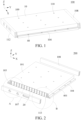
FIG. 1 is a schematic diagram of a structure of a battery pack according to an embodiment of the present disclosure; -
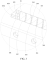
FIG. 2 is an exploded view of a battery pack housing according to an embodiment of the present disclosure; -
FIG. 3 is a partial enlarged view of A shown inFIG. 2 ; -
FIG. 4 is a partial enlarged view of B shown inFIG. 2 ; and -
FIG. 5 is a schematic diagram of a structure of an electric vehicle according to an embodiment of the present disclosure. -
- 100: battery pack; 200: battery pack housing; and 300: electric vehicle;
- 10: housing body; 101: top plate; 102: bottom plate; 103: first frame; 1031: first frame part; 1032: second frame part; 104: second frame; 1041: third frame part; 1042: fourth frame part; 105: reinforcement plate; 106: sub-cavity; 107: third frame; 108: fourth frame; 109: adhesive application hole; 110: exhaust orifice; 111: cavity; 112: end plate; and 113: first opening;
- 20: structural beam; 201: recess; 202: heat dissipation channel; 203: first side plate; 204: second side plate; and 205: partition plate;
- 30: accommodation cavity; and
- 40: mounting portion; and 401: mounting hole.
- Embodiments of the present disclosure are described in detail below, and examples of the embodiments are shown in accompanying drawings, where the same or similar elements or the elements having same or similar functions are denoted by the same or similar reference numerals throughout the description. The embodiments that are described with reference to the accompanying drawings are exemplary, and are only used to interpret the present disclosure, instead limiting the present disclosure.
- In the description of the present disclosure, it should be understood that, orientations or position relationships indicated by terms such as "center", "longitudinal", "transverse", "length", "width", "thickness", "up", "down", "front", "back", "left", "right", "vertical", "horizontal", "top", "bottom", "inner", "outer", "axial", "radial", and "circumferential" are orientations or position relationship shown based on the accompanying drawings, and are merely used for describing the present disclosure and simplifying the description, rather than indicating or implying that the apparatus or element should have a particular orientation or be constructed and operated in a particular orientation, and therefore, should not be construed as a limitation to the present disclosure.
- As shown in
FIG. 1 to FIG. 3 , the present disclosure provides abattery pack housing 200 including ahousing body 10 and at least onestructural beam 20 inside thehousing body 10, and the at least onestructural beam 20 divides the internal space of thehousing body 10 into a number of accommodation cavities 30. Thehousing body 10 includes atop plate 101 and abottom plate 102 arranged opposite to each other in a first direction, where the first direction is a height direction of thebattery pack housing 200, thestructural beam 20 locates between thetop plate 101 and thebottom plate 102, and the at least onestructural beam 20 is attached to thetop plate 101 and thebottom plate 102. Thebattery pack housing 200 is arranged with amounting portion 40 for a fixed connection with an external load. The first direction is the direction of a Z-axis in the figure. - The
battery pack housing 200 disclosed in the present disclosure includes thestructural beam 20 between thetop plate 101 and thebottom plate 102, and thestructural beam 20 is attached to thetop plate 101 and thebottom plate 102. This arrangement of thestructural beam 20, thetop plate 101, and thebottom plate 102 forms a "I"-shaped structure which has relatively high strength and stiffness, so that the requirements on load-bearing, impact resistance, crush resistance, etc. of thebattery pack housing 200 can be satisfied. In addition, thebattery pack housing 200 disclosed in the present disclosure relatively has a simple structure, low manufacturing costs, and high space utilization. Further, thestructural beam 20 divides thehousing body 10 into a number of the accommodation cavities 30, so that when thermal runaway occurs in a cell assembly or an individual cell in one of the accommodation cavities 30, the other accommodation cavities 30 are not impacted, thereby improving the safety of using thebattery pack 100. In addition, when such abattery pack 100 is mounted onto a whole vehicle, the structural strength of thebattery pack 100 can be taken as a part of the structural strength of the whole vehicle, so that the structural strength of the entire vehicle can be enhanced, which facilitates fulfilling the design requirement of the whole electric to be lightweight and reducing the costs of designing and manufacturing the whole vehicle. - It should be noted that the
battery pack housing 200 disclosed in the present disclosure refers to a housing of thebattery pack 100 for accommodating a cell assembly, an individual cell, or the like. Through the mountingportion 40 thereon, thebattery pack housing 200 is fixed to an external load in a detachable or non-detachable connection, and thus does not refer to a battery case for a battery module or an individual cell. Generally, thebattery pack 100 further includes at least one of a battery management system (BMS), a battery connector, a battery sampler, and a battery thermal management system. - The cell assembly includes an encapsulation film and at least one electrode core encapsulated by using the encapsulation film. The electrode core is a commonly used electrode core in the field of traction batteries, and can be an electrode core made by winding or an electrode core made by stacking. Generally, the electrode core includes at least a positive plate, a membrane, and a negative plate.
- In addition, that the
structural beam 20 is attached to thetop plate 101 and thebottom plate 102 can be understood as that thetop plate 101, thebottom plate 102, and thestructural beam 20 are integrally formed with one another. Alternatively, one of thetop plate 101 and thebottom plate 102 is integrally formed with thestructural beam 20, and the other is welded to thestructural beam 20. Alternatively, one end of thestructural beam 20 is welded to thebottom plate 102, and the other end of thestructural beam 20 is welded to thetop plate 101. - In one embodiment, as shown in
FIG. 2 , a length of the accommodation cavities 30 in a second direction is greater than 500 mm. According to some embodiments of the present disclosure, the length of the accommodation cavities 30 in the second direction is 500 mm to 2,500 mm. The second direction is different from the first direction, and the second direction is the direction of a Y-axis in the figure. The size of the accommodation cavities 30 allows thebattery pack 100 to meet the requirements for a relatively large capacity and relatively high space utilization. - According to some embodiments of the present disclosure, the length of the accommodation cavities 30 in the second direction is 1,000 mm to 2,000 mm.
- According to some embodiments of the present disclosure, the length of the accommodation cavities 30 in the second direction is 1,300 mm to 2,200 mm.
- In this embodiment, the second direction is a width direction of the
battery pack housing 200, or the second direction is a length direction of thebattery pack housing 200. - In one embodiment, as shown in
FIG. 2 to FIG. 3 , there are a number ofstructural beams 20, lengths of thestructural beams 20 extend in a second direction, a number of thestructural beams 20 are spaced in a third direction, and each of thestructural beams 20 is attached to atop plate 101 and abottom plate 102. The first direction, the second direction, and the third direction are different from each other, and the third direction is the direction of an X-axis in the figure. - In one embodiment, a
housing body 10 and thestructural beams 20 are integrally formed with each other. This arrangement not only allows a simple manufacturing process, which reduces the production costs, but also ensures sufficient structural strength and stiffness of the housing body, so as to meet the requirements on load-bearing, impact resistance and crush resistance of the housing body. - Specifically, the
top plate 101, thebottom plate 102, and thestructural beams 20 are integrally formed with one another. - In one embodiment, the second direction is a length direction of the
battery pack housing 200, and the third direction is a width direction of thebattery pack housing 200; or the second direction is a width direction of thebattery pack housing 200, and the third direction is a length direction of thebattery pack housing 200. - It can be understood that, as each of the
structural beams 20 is attached to thetop plate 101 and thebottom plate 102, eachstructural beam 20, thetop plate 101, and thebottom plate 102 form a "I"-shaped structure which has relatively high strength and stiffness, so that the requirements on load-bearing, impact resistance, crush resistance, etc. of thebattery pack housing 200 can be satisfied. Moreover, thebattery pack housing 200 relatively has a simple structure and high space utilization. In addition, thehousing body 10 and thestructural beams 20 are integrally formed with each other, and the manufacturing thereof is simple, so that the production costs can be reduced. When such abattery pack 100 is mounted onto a whole vehicle, the structural strength of thebattery pack 100 can be taken as a part of the structural strength of the whole vehicle, so that the structural strength of the entire vehicle can be enhanced, which facilitates fulfilling the design requirement of the whole electric to be lightweight and reducing the costs of designing and manufacturing the whole vehicle. - In one embodiment, as shown in
FIG. 2 to FIG. 4 , thehousing body 10 further includes afirst frame 103 and asecond frame 104 on two sides of thehousing body 10 in a third direction, and the third direction is a width direction of thebattery pack housing 200, or the third direction is a length direction of thebattery pack housing 200. The third direction is the direction of an X-axis in the figure. - In some embodiments, the
housing body 10 includes atop plate 101 and abottom plate 102 arranged opposite to each other in a first direction and afirst frame 103 and asecond frame 104 arranged opposite to each other in a third direction. Thetop plate 101, thefirst frame 103, thebottom plate 102, and thesecond frame 104 are connected. - It can be understood that the
top plate 101, thefirst frame 103, thebottom plate 102, and thesecond frame 104 collectively define an accommodation space. Thestructural beams 20 are in the accommodation space. According to some embodiments of the present disclosure, thetop plate 101, thefirst frame 103, thebottom plate 102, and thesecond frame 104 are integrally formed with one another, and this arrangement can ensure relatively high structural strength of thehousing body 10, while the manufacturing is relatively simple, thereby helping reduce the production costs. Clearly, in other embodiments, thefirst frame 103 and thesecond frame 104 may be connected to thetop plate 101 and thebottom plate 102 through an intermediate plate. Alternatively, one end of thefirst frame 103 is welded to thetop plate 101, and the other end of thefirst frame 103 is welded to thebottom plate 102. Similarly, one end of thefirst frame 103 is welded to thetop plate 101, and the other end of thefirst frame 103 is welded to thebottom plate 102. - In one embodiment of the present disclosure, the
top plate 101, thefirst frame 103, thebottom plate 102, thesecond frame 104, and thestructural beams 20 are integrally formed with one another, for example, by integrated aluminum extrusion. This not only ensures the relatively high structural strength of thebattery pack housing 200, but also simplifies the manufacturing to reduce the processing costs. Clearly, in other embodiments, thetop plate 101, thebottom plate 102, and thestructural beams 20 are integrally formed with one another as one piece. Then, thefirst frame 103 is welded to thetop plate 101 and thebottom plate 102, and thesecond frame 104 is welded to thetop plate 101 and thebottom plate 102. - In some embodiments, the first direction is a height direction of the
battery pack housing 200, the second direction is one of a width direction and a length direction of thebattery pack housing 200, and the third direction is the other of the width direction and the length direction of thebattery pack housing 200. In other words, the second direction is a width direction of thebattery pack housing 200, and the third direction is a length direction of thebattery pack housing 200; or the second direction is a length direction of thebattery pack housing 200, and the third direction is a width direction of thebattery pack housing 200. - In this embodiment of the present disclosure, the second direction is a width direction of the
battery pack housing 200 and is parallel to a width direction of anelectric vehicle 300. The third direction is a length direction of thebattery pack housing 200 and is parallel to a length direction of theelectric vehicle 300. - Clearly, in other embodiments, the second direction may be parallel to the length direction of the
electric vehicle 300, and the third direction may be parallel to the width direction of theelectric vehicle 300. - According to some embodiments of the present disclosure, as shown in
FIG. 2 to FIG. 4 , at least one of thefirst frame 103 and thesecond frame 104 has acavity 111 inside.Reinforcement plates 105 are arranged in thecavity 111, and thereinforcement plates 105 divide thecavity 111 into a number ofsub-cavities 106. This arrangement can ensure that thefirst frame 103 and thesecond frame 104 have specific strength, which helps improve the strength of thebattery pack 100 to resist being impacted or crushed. - In one embodiment, as shown in
FIG. 1 and FIG. 2 , thefirst frame 103 and thesecond frame 104 are arranged with a mountingportion 40 for a fixed connection with an external load. Clearly, in other embodiments, the mountingportion 40 may be arranged on thetop plate 101 or thebottom plate 102. - In one embodiment, as shown in
FIG. 1 and FIG. 2 , the mountingportion 40 is mountingholes 401 arranged on thefirst frame 103 and thesecond frame 104. The mountingholes 401 are used for getting fasteners (such as bolts or rivets) through to fix thebattery pack 100 to an external load. - In some embodiments, the mounting
holes 401 on thefirst frame 103 is distributed all over thefirst frame 103 in a first direction, and the mountingholes 401 on thesecond frame 104 is distributed all over thesecond frame 104 in a first direction. However, an axial direction of the mountingholes 401 may alternatively be arranged with an included angle, for example, 5 degrees or 10 degrees, relative to the first direction. - According to some embodiments of the present disclosure, there are a number of mounting
holes 401, and the mountingholes 401 on thefirst frame 103 are arranged one by one in order in a length direction of thefirst frame 103. The length direction of thefirst frame 103 is parallel to the second direction. - Similarly, the mounting
holes 401 on thesecond frame 104 are arranged one by one in order in a length direction of thesecond frame 104. The length direction of thesecond frame 104 is parallel to the second direction. - Clearly, in another embodiment, the mounting
portion 40 is rings arranged on thefirst frame 103 and thesecond frame 104. The rings are fixedly connected to an external load, to fixedly connect thebattery pack 100 to the external load. - However, in another embodiment, the mounting
portion 40 is mounting blocks arranged on thefirst frame 103 and thesecond frame 104. The mounting blocks is fixed to an external load by welding. Clearly, the mounting blocks may alternatively be fixed to the external load by using adhesive or by clamping. - In one embodiment, as shown in
FIG. 2 to FIG. 4 , thefirst frame 103 includes afirst frame part 1031 and asecond frame part 1032, and thesecond frame 104 includes athird frame part 1041 and afourth frame part 1042. Thefirst frame part 1031 and thethird frame part 1041 are arranged opposite to each other in a second direction and are connected to thetop plate 101 and thebottom plate 102. Thesecond frame part 1032 is on one side of thefirst frame part 1031 that is farther from thethird frame part 1041, and thefourth frame part 1042 is on one side of thethird frame part 1041 farther from thefirst frame part 1031. The mountingportion 40 is arranged on thesecond frame part 1032 and thefourth frame part 1042. - According to some embodiments of the present disclosure, the
first frame part 1031 is perpendicular to thesecond frame part 1032, forming an L-shaped structure. This arrangement helps enhance the structural strength of thefirst frame 103. Thethird frame part 1041 is perpendicular to thefourth frame part 1042, forming an L-shaped structure. This arrangement helps enhance the structural strength of thesecond frame 104. However, thefirst frame part 1031 and thesecond frame part 1032, as well as thethird frame part 1041 and thefourth frame part 1042 may be arranged with another included angle, for example, 70 degrees or 80 degrees. - In one embodiment, as shown in the figure, the
battery pack housing 200 further includes anend plate 112, afirst opening 113 is arranged at an end of thehousing body 10 in a second direction, theend plate 112 seals up thefirst opening 113, and the second direction is a width direction of thebattery pack housing 200, or the second direction is a length direction of thebattery pack housing 200. - It can be understood that a cell assembly or an individual cell may be mounted inside the accommodation cavities 30 through the
first opening 113, and the manner is easy for operation. In addition, electrodes of the cell assembly or individual cell inside the accommodation cavities 30 can be led out through thefirst opening 113 while ensuring relatively high structural strength of thebattery pack housing 200. - According to some embodiments of the present disclosure, the
first opening 113 is arranged in the second direction at both ends of thehousing body 10; and theend plate 112 includes athird frame 107 and afourth frame 108. Thethird frame 107 and thefourth frame 108 are sealingly connected to thehousing body 10 to seal up the correspondingfirst opening 113. - It can be understood that when the
first opening 113 is arranged in the second direction at both ends of thehousing body 10, the electrodes of the cell assembly or the individual cell inside the accommodation cavities 30 can be led out through the twofirst openings 113 respectively. - According to some embodiments of the present disclosure, the
housing body 10, thethird frame 107, and thefourth frame 108 are metal pieces and are sealingly connected by welding. - However, in other embodiments, the
housing body 10, thethird frame 107, and thefourth frame 108 may be made of plastic. In addition, thethird frame 107 and thefourth frame 108 may be sealingly connected to thehousing body 10 by using adhesive or by clamping. - According to some embodiments of the present disclosure, as shown in
FIG. 2 to FIG. 4 , thethird frame 107 and thefourth frame 108 are hollow inside.Reinforcement plates 105 are arranged in thethird frame 107 and thefourth frame 108, and thereinforcement plates 105 divide the internal spaces of thethird frame 107 and thefourth frame 108 into a number ofsub-cavities 106. This arrangement can ensure that thethird frame 107 and thefourth frame 108 have specific strength, which helps improve the strength of thebattery pack housing 200 to resist being impacted or crushed. - In one embodiment, the
battery pack housing 200 further includes a sealing plate, a second opening is arranged at an end of the accommodation cavities 30 in the second direction, where the sealing plate is arranged inside theend plate 112. The sealing plate is connected to thestructural beams 20 and thehousing body 10 to block off a portion that is of the second opening of the accommodation cavities 30 and that is adjacent to thebottom plate 102. To be specific, the second opening of the accommodation cavities 30 is half blocked-off by using the sealing plate, so that when the accommodation cavities 30 accommodate an electrode core assembly encapsulated by using an encapsulation film, unexpected breakage of the encapsulation film can be prevented to cause a flow of electrolyte from one accommodation cavity 30 to another accommodation cavity 30 which leads to an internal short circuit, thereby improving the safety of using thebattery pack 100. - The half blockage of the second opening of an accommodation cavity 30 that is in a number of the accommodation cavities 30 and that is at either end may be that the sealing plate is connected to the
first frame 103, thebottom plate 102, and thestructural beams 20, or that the sealing plate is connected to thesecond frame 104, thebottom plate 102, and thestructural beams 20, to block off a portion that is of the second opening of the accommodation cavity 30 and that is adjacent to thebottom plate 102. - The half blockage of the second opening of another accommodation cavity 30 in a number of the accommodation cavities 30 may be that the sealing plate is connected to the
bottom plate 102 and two adjacentstructural beams 20, to block off a portion that is of the second opening of the accommodation cavity 30 and that is adjacent to thebottom plate 102. - In one embodiment, as shown in the figure, the
battery pack housing 200 further includes a sealing plate, a second opening is arranged at an end of the accommodation cavities 30 in the second direction, where the sealing plate is arranged inside theend plate 112. The sealing plate is connected to thestructural beams 20 and thehousing body 10 to completely block off the second opening of the accommodation cavities 30. That is, the second opening of the accommodation cavities 30 is completely blocked off by using the sealing plate, so that the safety of using thebattery pack 100 is improved. - The complete blockage of the second opening of an accommodation cavity 30 that is in a number of the accommodation cavities 30 and that is at either end may be that the sealing plate is connected to the
first frame 103, thestructural beams 20, thetop plate 101, and thebottom plate 102, or that the sealing plate is connected to thesecond frame 104, thestructural beams 20, thetop plate 101, and thebottom plate 102, to completely block off the second opening of the accommodation cavity 30. - The complete blockage of the second opening of another accommodation cavity 30 in a number of the accommodation cavities 30 may be that the sealing plate is connected to the
bottom plate 102, thetop plate 101, and two adjacentstructural beams 20, to completely block off the second opening of the accommodation cavity 30. - In one embodiment, as shown in
FIG. 1 and FIG. 2 , arecess 201 recessed away from theend plate 112 is arranged at an end of the at least onestructural beam 20 in the second direction. - The structural design of the
recess 201 can be used for accommodating an insulation protection frame, an electrical connector, etc., and this structural design does not increase the length of thebattery pack housing 200 in the second direction, which helps reduce the size of thebattery pack housing 200. - According to some embodiments of the present disclosure, each
structural beam 20 is arranged with therecess 201 at either end in the second direction, where therecess 201 adjacent to thethird frame 107 draws back from thethird frame 107, and therecess 201 adjacent to thefourth frame 108 draws back from thefourth frame 108. - In one embodiment, as shown in
FIG. 2 to FIG. 4 , aheat dissipation channel 202 is arranged in the at least onestructural beam 20. Theheat dissipation channel 202 extends in a second direction, and the second direction is a width direction of thebattery pack housing 200, or the second direction is a length direction of thebattery pack housing 200. In this way, after getting into theheat dissipation channel 202, the heat from the cell assembly or the individual cell accommodated in the accommodation cavities 30 can be transferred to the outside of thebattery pack housing 200 via thetop plate 101 and thebottom plate 102. This structural design in the present disclosure provides a larger heat dissipation space inside thebattery pack housing 200 when compared with a solid-structure design of thestructural beam 20, thereby helping improve the cooling and heat dissipation effects. - In one embodiment, as shown in
FIG. 2 to FIG. 4 , eachstructural beam 20 includes afirst side plate 203 and asecond side plate 204 arranged at intervals in a third direction, thefirst side plate 203, thesecond side plate 204, thetop plate 101, and thebottom plate 102 collectively define theheat dissipation channel 202, the second direction is a width direction of thebattery pack housing 200, and the third direction is a length direction of thebattery pack housing 200; or, the second direction is a length direction of thebattery pack housing 200, and the third direction is a width direction of thebattery pack housing 200. - That is, the space surrounded by the
first side plate 203, thesecond side plate 204, thetop plate 101, and thebottom plate 102 is theheat dissipation channel 202. In this way, theheat dissipation channel 202 can be formed simply by utilizing the structure of thehousing body 10 and thestructural beam 20 without an additional heat dissipation pipe, thereby helping simplify the structural design of thebattery pack 100 and reduce the production costs. - In one embodiment, as shown in
FIG. 2 andFIG. 4 , thestructural beam 20 further includes apartition plate 205 connected to both thefirst side plate 203 and thesecond side plate 204, and thepartition plate 205 divides theheat dissipation channel 202 into a number of sub-channels. This arrangement can bring better cooling and heat dissipation effects of thebattery pack housing 200, and at the same time can ensure specific strength of thestructural beam 20, thereby helping improve of the overall strength of thebattery pack 100. - In one embodiment, as shown in
FIG. 1 and FIG. 2 , thebattery pack housing 200 is arranged with anadhesive application hole 109, and each of the accommodation cavities 30 is in a corresponding communication with the at least oneadhesive application hole 109. It can be understood that a structural adhesive can be injected into thebattery pack housing 200 through theadhesive application hole 109 to fixedly connect the cell assembly or the individual cell accommodated in the accommodation cavities 30 to thebattery pack housing 200, thereby improving the structural strength of thebattery pack 100. - In one embodiment, the
battery pack housing 200 is a sealed housing, and an air pressure inside the accommodation cavities 30 is lower than an air pressure outside thebattery pack housing 200. This arrangement allows a vacuum-pumping operation to get the air pressure inside the accommodation cavities 30 lower than the air pressure outside thebattery pack housing 200, which can reduce an existing amount of substances such as water vapor inside thebattery pack housing 200, so as to prevent aging, damage, etc. of a component, for example, the cell assembly or the cell, inside thebattery pack housing 200 due to a long-term effect of water vapor, thereby helping prolong the service life of thebattery pack 100. In addition, the sealed housing may further function as a secondary seal. - In one embodiment, the pressure inside the accommodation cavities 30 is -40 KPa to -70 KPa. This arrangement can ensure that an existing amount of substances such as water vapor and oxygen inside the
battery pack housing 200 is reduced, so as to prevent aging of the cell assembly or various other components inside thebattery pack housing 200 due to a long-term effect of water vapor and oxygen, thereby helping prolong the service life of the cell assembly or various other components inside thebattery pack housing 200. - In one embodiment, as shown in
FIG. 1 and FIG. 2 , thebattery pack housing 200 is arranged with anexhaust orifice 110. An operation of vacuum-pumping from inside thebattery pack housing 200 through theexhaust orifice 110 can reduce an existing amount of substances such as water vapor inside thebattery pack housing 200, so as to prevent aging, damage, etc. of a component, for example, the cell assembly or the cell, inside thebattery pack housing 200 due to a long-term effect of water vapor, thereby helping prolong the service life of thebattery pack 100. - In one embodiment, as shown in
FIG. 1 and FIG. 2 , thebattery pack housing 200 is arranged with a number ofexhaust orifices 110, and a number of theexhaust orifices 110 are in a corresponding communication with a number of the accommodation cavities 30. This arrangement helps enhance the efficiency of the vacuum-pumping operation and reduce the production costs. - In one embodiment, as shown in
FIG. 1 and FIG. 2 , a number of the accommodation cavities 30 are in a communication with each other, and thebattery pack housing 200 is arranged with at least oneexhaust orifice 110 that is in a communication with the accommodation cavities 30. In this way, an operation of vacuum-pumping from a number of the accommodation cavities 30 at the same time through theexhaust orifice 110 can be performed. - It should be noted that a type of the communication with the accommodation cavities 30 is not specifically limited. For example, the accommodation cavities 30 may achieve the communication through the
first opening 113 at the end. Alternatively, thestructural beam 20 is arranged with a through hole that communicates two adjacent accommodation cavities 30. - According to some embodiments of the present disclosure, as shown in
FIG. 1 , thetop plate 101 is arranged with theadhesive application hole 109 or theexhaust orifice 110 or theadhesive application hole 109 and theexhaust orifice 110. However, in other embodiments, it may be that thebottom plate 102, thefirst frame 103, or thesecond frame 104 is arranged with theadhesive application hole 109 or theexhaust orifice 110 or theadhesive application hole 109 and theexhaust orifice 110. - Further, a manner of sealing the
exhaust orifice 110 is not specifically limited. For example, theexhaust orifice 110 may be sealed by a sealing member or may be sealed by using a potting adhesive. - It should be noted that the
adhesive application hole 109 and theexhaust orifice 110 may be the same hole or different holes. In the case in which the two holes are the same holes, it may be that a potting adhesive is used and then vacuum-pumping is performed. - Another aspect of the present disclosure provides a
battery pack 100 including thebattery pack housing 200 described above. Thebattery pack 100 provided in the present disclosure has relatively high structural strength and stiffness, relatively high space utilization, as well as relatively high safety in use. - In still another aspect, the present disclosure further provides an
electric vehicle 300 including a vehicle body and thebattery pack 100 described above, and thebattery pack 100 is fixed to the vehicle body through the mountingportion 40. - According to the electric vehicle 300 (see
FIG. 5 ) provided in the present disclosure, when thebattery pack 100 having relatively high strength is mounted onto a whole vehicle, the structural strength of thebattery pack 100 can be taken as a part of the structural strength of the whole vehicle, so that the structural strength of the entire vehicle can be enhanced, which facilitates fulfilling the design requirement of the whole electric to be lightweight and reducing the costs of designing and manufacturing the whole vehicle. - In the description of the present disclosure, it should be noted that unless otherwise explicitly specified or defined, the terms such as "mount", "install", "connect", and "connection" should be understood in a broad sense. For example, the connection may be a fixed connection, a detachable connection, or an integral connection; or the connection may be a mechanical connection or an electrical connection; or the connection may be a direct connection, an indirect connection through an intermediary, or internal communication between two components. A person of ordinary skill in the art may understand the specific meanings of the foregoing terms in the present disclosure according to specific situations.
- In description of this specification, description of reference terms such as "an embodiment", "specific embodiments", or "an example", means including specific features, structures, materials, or features described in this embodiment or example in at least one embodiment or example of the present disclosure. In this specification, schematic descriptions of the foregoing terms do not necessarily point at a same embodiment or example. Moreover, the specific features, structures, materials, or characteristics described may be combined in any one or more embodiments or examples in an appropriate manner.
- Although the embodiments of the present disclosure have been shown and described, persons of ordinary skill in the art should understand that various changes, modifications, replacements and variations may be made to the embodiments without departing from the principles and spirit of the present disclosure, and the scope of the present disclosure is as defined by the appended claims and their equivalents.
Claims (24)
- A battery pack housing, comprising a housing body and at least one structural beam inside the housing body, wherein the at least one structural beam divides the internal space of the housing body into a plurality of accommodation cavities;the housing body comprises a top plate and a bottom plate arranged opposite to each other in a first direction, the first direction is a height direction of the battery pack housing, the structural beam locates between the top plate and the bottom plate, and the at least one structural beam is attached to the top plate and the bottom plate;the battery pack housing is arranged with a mounting portion for a fixed connection with an external load.
- The battery pack housing according to claim 1, wherein the length of the accommodation cavities in a second direction is greater than 500 mm, and the second direction is a width direction of the battery pack housing, or the second direction is a length direction of the battery pack housing.
- The battery pack housing according to claim 1, wherein there are a plurality of the structural beams, lengths of the structural beams extend in a second direction, the plurality of structural beams are spaced in a third direction, each of the structural beams is attached to the top plate and the bottom plate, the second direction is a length direction of the battery pack housing, and the third direction is a width direction of the battery pack housing; or, the second direction is a width direction of the battery pack housing, and the third direction is a length direction of the battery pack housing.
- The battery pack housing according to claim 1, wherein the housing body is integrally formed with the structural beams.
- The battery pack housing according to claim 1, wherein the housing body comprises a first frame and a second frame on two sides of the housing body in a third direction, and the third direction is a width direction of the battery pack housing, or the third direction is a length direction of the battery pack housing.
- The battery pack housing according to claim 5, wherein at least one of the first frame and the second frame has a cavity inside, reinforcement plates are arranged in the cavity, and the reinforcement plates divide the cavity into a plurality of sub-cavities.
- The battery pack housing according to claim 5, wherein the mounting portion is arranged on the first frame and the second frame.
- The battery pack housing according to claim 5, wherein the battery pack housing further comprises an end plate, a first opening is arranged at an end of the housing body in a second direction, the end plate seals up the first opening, and the second direction is a width direction of the battery pack housing, or the second direction is a length direction of the battery pack housing.
- The battery pack housing according to claim 8, wherein the first opening is arranged in the second direction at both ends of the housing body; and the end plate comprises a third frame and a fourth frame, wherein the third frame and the fourth frame are sealingly connected to the housing body to seal up the corresponding first opening.
- The battery pack housing according to claim 9, wherein the housing body, the third frame, and the fourth frame are metal pieces and are sealingly connected by welding.
- The battery pack housing according to claim 8, wherein the battery pack housing further comprises a sealing plate, a second opening is arranged at an end of the accommodation cavities in the second direction, the sealing plate is arranged inside the end plate, and the sealing plate occludes a portion that is of the second opening and that is adjacent to the bottom plate.
- The battery pack housing according to claim 8, wherein the battery pack housing further comprises a sealing plate, a second opening is arranged at an end of the accommodation cavities in the second direction, the sealing plate is arranged inside the end plate, and the sealing plate completely occludes the second opening.
- The battery pack housing according to claim 8, wherein a recess recessed away from the end plate is arranged at an end of the at least one structural beam in the second direction.
- The battery pack housing according to any one of claims 1 to 13, wherein a heat dissipation channel is arranged in the at least one structural beam, the heat dissipation channel extends in a second direction, and the second direction is a width direction of the battery pack housing, or the second direction is a length direction of the battery pack housing.
- The battery pack housing according to claim 14, wherein each of the structural beams comprises a first side plate and a second side plate arranged at intervals in a third direction, the first side plate, the second side plate, the top plate, and the bottom plate collectively define the heat dissipation channel, the second direction is a width direction of the battery pack housing, and the third direction is a length direction of the battery pack housing; or, the second direction is a length direction of the battery pack housing, and the third direction is a width direction of the battery pack housing.
- The battery pack housing according to claim 15, wherein the structural beam further comprises a separator connected to both the first side plate and the second side plate, and the separator divides the heat dissipation channel into a plurality of sub-channels.
- The battery pack housing according to claim 1, wherein the battery pack housing is arranged with an adhesive application hole, and each of the accommodation cavities is in a corresponding communication with the at least one adhesive application hole.
- The battery pack housing according to claim 1, wherein the battery pack housing is a sealed housing, and an air pressure inside the accommodation cavities is lower than an air pressure outside the battery pack housing.
- The battery pack housing according to claim 18, wherein the pressure inside the accommodation cavities is -40 KPa to -70 KPa.
- The battery pack housing according to claim 18, wherein the battery pack housing is arranged with an exhaust orifice.
- The battery pack housing according to claim 20, wherein the battery pack housing is arranged with a plurality of exhaust orifices, and the plurality of exhaust orifices are in a corresponding communication with the plurality of accommodation cavities respectively.
- The battery pack housing according to claim 20, wherein the plurality of accommodation cavities are in a communication with each other, and the battery pack housing is arranged with at least one exhaust orifice that is in a communication with the accommodation cavities.
- A battery pack, comprising the battery pack housing according to any one of claims 1 to 22.
- An electric vehicle, comprising a vehicle body and the battery pack according to claim 23, wherein the battery pack is fixed to the vehicle body through the mounting portion.
Applications Claiming Priority (2)
| Application Number | Priority Date | Filing Date | Title |
|---|---|---|---|
| CN202020637729.0U CN210984839U (en) | 2020-04-24 | 2020-04-24 | A battery pack case, battery pack and electric vehicle |
| PCT/CN2020/128118 WO2021212815A1 (en) | 2020-04-24 | 2020-11-11 | Battery pack box, battery pack and electric vehicle |
Publications (2)
| Publication Number | Publication Date |
|---|---|
| EP4138179A1 true EP4138179A1 (en) | 2023-02-22 |
| EP4138179A4 EP4138179A4 (en) | 2024-07-17 |
Family
ID=71416100
Family Applications (1)
| Application Number | Title | Priority Date | Filing Date |
|---|---|---|---|
| EP20931797.3A Pending EP4138179A4 (en) | 2020-04-24 | 2020-11-11 | BATTERY PACK CASE, BATTERY PACK AND ELECTRIC VEHICLE |
Country Status (6)
| Country | Link |
|---|---|
| US (1) | US20230042566A1 (en) |
| EP (1) | EP4138179A4 (en) |
| JP (1) | JP7627286B2 (en) |
| KR (1) | KR102901141B1 (en) |
| CN (1) | CN210984839U (en) |
| WO (1) | WO2021212815A1 (en) |
Families Citing this family (17)
| Publication number | Priority date | Publication date | Assignee | Title |
|---|---|---|---|---|
| CN210984839U (en) * | 2020-04-24 | 2020-07-10 | 比亚迪股份有限公司 | A battery pack case, battery pack and electric vehicle |
| CN113782899B (en) * | 2020-05-22 | 2024-05-07 | 比亚迪股份有限公司 | Battery pack shell, battery pack and electric vehicle |
| US20240039071A1 (en) * | 2020-12-10 | 2024-02-01 | Microvast Power Systems Co., Ltd. | Battery housing, lithium-ion secondary battery, and electric vehicle |
| CN215794235U (en) * | 2021-01-27 | 2022-02-11 | 纳恩博(常州)科技有限公司 | Battery compartment for electric scooter, battery compartment assembly and electric scooter |
| CN115693820A (en) * | 2021-07-30 | 2023-02-03 | 比亚迪股份有限公司 | Battery pack charging system and charging device |
| CN114940214B (en) * | 2021-08-31 | 2023-02-10 | 比亚迪股份有限公司 | Vehicle body and vehicle with same |
| CN116169411B (en) * | 2021-11-24 | 2024-09-10 | 比亚迪股份有限公司 | Battery and vehicle with same |
| CN114497925A (en) * | 2022-01-28 | 2022-05-13 | 欣旺达电动汽车电池有限公司 | Battery pack and glue injection method thereof |
| CN114725597B (en) * | 2022-03-25 | 2024-03-12 | 江苏天钧精密技术有限公司 | A high-strength and lightweight battery box with a mortise and tenon structure and a manufacturing method thereof |
| CN114784354B (en) * | 2022-04-11 | 2025-05-23 | 中创新航科技集团股份有限公司 | Battery device, assembling method thereof, assembling equipment and battery assembly positioning tool |
| JP7808195B2 (en) * | 2022-06-29 | 2026-01-28 | 香港時代新能源科技有限公司 | Housing, battery and power consuming device |
| CN116250138B (en) * | 2022-06-29 | 2025-02-18 | 宁德时代新能源科技股份有限公司 | Box, battery and power consumption device |
| CN116231222A (en) * | 2023-03-30 | 2023-06-06 | 孚能科技(赣州)股份有限公司 | Battery case and battery pack |
| CN116729487B (en) * | 2023-04-17 | 2026-03-06 | 一汽解放汽车有限公司 | An MTC battery frame and a commercial electric vehicle |
| WO2024221165A1 (en) * | 2023-04-24 | 2024-10-31 | 宁德时代(上海)智能科技有限公司 | Side beam structure, chassis and vehicle |
| CN119297497A (en) * | 2024-09-13 | 2025-01-10 | 惠州亿纬锂能股份有限公司 | Beam structure, battery box and battery pack |
| CN119786860B (en) * | 2025-01-03 | 2025-10-28 | 蜂巢能源科技股份有限公司 | Battery pack and electric equipment |
Family Cites Families (22)
| Publication number | Priority date | Publication date | Assignee | Title |
|---|---|---|---|---|
| US6255015B1 (en) * | 1998-08-23 | 2001-07-03 | Ovonic Battery Company, Inc. | Monoblock battery assembly |
| JP3640846B2 (en) | 1999-10-14 | 2005-04-20 | ダイハツ工業株式会社 | Battery cooling device for electric vehicle |
| DE102015111749A1 (en) | 2015-07-20 | 2017-01-26 | Dr. Ing. H.C. F. Porsche Aktiengesellschaft | Battery device and method |
| FR3042093B1 (en) | 2015-10-05 | 2017-10-06 | Blue Solutions | ELECTRIC ENERGY STORAGE MODULE AND METHOD FOR MANUFACTURING THE SAME |
| JP2017124698A (en) | 2016-01-13 | 2017-07-20 | トヨタ自動車株式会社 | Battery mounting structure |
| CN108886121B (en) | 2016-04-01 | 2021-11-30 | 株式会社Lg化学 | Battery module |
| CN206022451U (en) * | 2016-07-19 | 2017-03-15 | 深圳市沃特玛电池有限公司 | A kind of battery case |
| DE102017106068A1 (en) | 2017-03-21 | 2018-09-27 | Obrist Technologies Gmbh | battery system |
| CN108630843B (en) * | 2017-03-23 | 2023-10-24 | 宁德时代新能源科技股份有限公司 | Battery pack protection frame and battery pack |
| KR102065099B1 (en) * | 2017-04-04 | 2020-01-10 | 주식회사 엘지화학 | Battery Pack having crash beam and drain structure |
| DE102017127807B4 (en) * | 2017-11-24 | 2019-06-27 | Dr. Ing. H.C. F. Porsche Aktiengesellschaft | Battery device for an at least partially electrically operated motor vehicle |
| KR102270234B1 (en) * | 2017-12-12 | 2021-06-25 | 주식회사 엘지에너지솔루션 | Battery module embedding cross beam and Battery pack comprising the battery module |
| IT201800002774A1 (en) * | 2018-02-16 | 2019-08-16 | Ferrari Spa | VEHICLE BATTERY PACK |
| JP7107139B2 (en) | 2018-09-27 | 2022-07-27 | トヨタ自動車株式会社 | battery pack |
| JP6990642B2 (en) * | 2018-10-18 | 2022-01-12 | 本田技研工業株式会社 | Power storage module and manufacturing method of power storage module |
| CN109616717A (en) * | 2018-11-08 | 2019-04-12 | 同济大学 | A vacuum battery pack system suitable for electric vehicles |
| CN209658277U (en) * | 2019-05-31 | 2019-11-19 | 宁德时代新能源科技股份有限公司 | battery module |
| CN110571378A (en) * | 2019-08-29 | 2019-12-13 | 广汽新能源汽车有限公司 | Battery case and battery system |
| CN111048868B (en) * | 2019-12-25 | 2022-01-28 | 中国第一汽车股份有限公司 | Battery monomer group and battery module |
| CN111312964B (en) * | 2020-04-24 | 2022-01-07 | 比亚迪股份有限公司 | Battery pack and electric vehicle |
| CN210984839U (en) * | 2020-04-24 | 2020-07-10 | 比亚迪股份有限公司 | A battery pack case, battery pack and electric vehicle |
| CN111293253B (en) * | 2020-04-24 | 2020-10-23 | 比亚迪股份有限公司 | Battery pack and electric vehicle |
-
2020
- 2020-04-24 CN CN202020637729.0U patent/CN210984839U/en active Active
- 2020-11-11 JP JP2022564543A patent/JP7627286B2/en active Active
- 2020-11-11 EP EP20931797.3A patent/EP4138179A4/en active Pending
- 2020-11-11 KR KR1020227041047A patent/KR102901141B1/en active Active
- 2020-11-11 WO PCT/CN2020/128118 patent/WO2021212815A1/en not_active Ceased
-
2022
- 2022-10-24 US US17/972,099 patent/US20230042566A1/en not_active Abandoned
Also Published As
| Publication number | Publication date |
|---|---|
| JP7627286B2 (en) | 2025-02-05 |
| EP4138179A4 (en) | 2024-07-17 |
| JP2023522474A (en) | 2023-05-30 |
| CN210984839U (en) | 2020-07-10 |
| US20230042566A1 (en) | 2023-02-09 |
| KR102901141B1 (en) | 2025-12-17 |
| KR20230006869A (en) | 2023-01-11 |
| WO2021212815A1 (en) | 2021-10-28 |
Similar Documents
| Publication | Publication Date | Title |
|---|---|---|
| US20230042566A1 (en) | Battery pack housing, battery pack, and electric vehicle | |
| US12620670B2 (en) | Battery pack and electric vehicle | |
| JP7541587B2 (en) | Battery packs and electric vehicles | |
| US20230080969A1 (en) | Battery pack and electric vehicle | |
| US11251487B2 (en) | Battery module and battery pack | |
| KR20190131415A (en) | Battery Pack comprising a Frame Profile with Integral Coolant Circuit Elements | |
| EP4156388B1 (en) | BATTERY PACK HOUSING, BATTERY PACK AND ELECTRIC VEHICLE | |
| EP4447197A1 (en) | Battery cooling system, battery pack, and vehicle | |
| CN212434741U (en) | Power battery pack structure | |
| CN107946503A (en) | Battery module carrier and battery system | |
| JP7483906B2 (en) | Battery pack and vehicle | |
| CN115149176B (en) | A lower box, a battery pack, an exhaust method, and an electric device | |
| CN222530669U (en) | Battery Pack | |
| CN212257515U (en) | Electric core isolation device of power battery pack of portable battery-replacing electric vehicle and power battery pack | |
| CA3178237C (en) | Battery pack housing, battery pack and electric vehicle | |
| CN113782901B (en) | Battery pack and electric vehicle | |
| CN222380743U (en) | Battery pack and power device with same | |
| CN222530703U (en) | Battery pack and vehicle | |
| CN223598857U (en) | Battery pack and vehicle | |
| CN113782897A (en) | Battery pack and vehicle having the same | |
| CN120674727A (en) | Frame construction, battery package and consumer | |
| CN119764730A (en) | Battery and electricity utilization device | |
| HK40026406A (en) | Battery pack and electric vehicle | |
| HK40026406B (en) | Battery pack and electric vehicle |
Legal Events
| Date | Code | Title | Description |
|---|---|---|---|
| STAA | Information on the status of an ep patent application or granted ep patent |
Free format text: STATUS: THE INTERNATIONAL PUBLICATION HAS BEEN MADE |
|
| PUAI | Public reference made under article 153(3) epc to a published international application that has entered the european phase |
Free format text: ORIGINAL CODE: 0009012 |
|
| STAA | Information on the status of an ep patent application or granted ep patent |
Free format text: STATUS: REQUEST FOR EXAMINATION WAS MADE |
|
| 17P | Request for examination filed |
Effective date: 20221117 |
|
| AK | Designated contracting states |
Kind code of ref document: A1 Designated state(s): AL AT BE BG CH CY CZ DE DK EE ES FI FR GB GR HR HU IE IS IT LI LT LU LV MC MK MT NL NO PL PT RO RS SE SI SK SM TR |
|
| DAV | Request for validation of the european patent (deleted) | ||
| DAX | Request for extension of the european patent (deleted) | ||
| RIC1 | Information provided on ipc code assigned before grant |
Ipc: H01M 50/244 20210101ALI20240319BHEP Ipc: H01M 50/233 20210101ALI20240319BHEP Ipc: H01M 50/30 20210101ALI20240319BHEP Ipc: H01M 50/249 20210101ALI20240319BHEP Ipc: H01M 50/224 20210101ALI20240319BHEP Ipc: H01M 50/209 20210101ALI20240319BHEP Ipc: H01M 10/6557 20140101ALI20240319BHEP Ipc: H01M 10/6555 20140101ALI20240319BHEP Ipc: H01M 10/625 20140101ALI20240319BHEP Ipc: H01M 10/613 20140101ALI20240319BHEP Ipc: B60L 50/64 20190101ALI20240319BHEP Ipc: H01M 50/10 20210101AFI20240319BHEP |
|
| A4 | Supplementary search report drawn up and despatched |
Effective date: 20240617 |
|
| RIC1 | Information provided on ipc code assigned before grant |
Ipc: H01M 50/244 20210101ALI20240611BHEP Ipc: H01M 50/233 20210101ALI20240611BHEP Ipc: H01M 50/30 20210101ALI20240611BHEP Ipc: H01M 50/249 20210101ALI20240611BHEP Ipc: H01M 50/224 20210101ALI20240611BHEP Ipc: H01M 50/209 20210101ALI20240611BHEP Ipc: H01M 10/6557 20140101ALI20240611BHEP Ipc: H01M 10/6555 20140101ALI20240611BHEP Ipc: H01M 10/625 20140101ALI20240611BHEP Ipc: H01M 10/613 20140101ALI20240611BHEP Ipc: B60L 50/64 20190101ALI20240611BHEP Ipc: H01M 50/10 20210101AFI20240611BHEP |