EP4138172A2 - Battery pack, vehicle equipped with battery pack, and replacement method of battery blocks in battery pack - Google Patents
Battery pack, vehicle equipped with battery pack, and replacement method of battery blocks in battery pack Download PDFInfo
- Publication number
- EP4138172A2 EP4138172A2 EP22185477.1A EP22185477A EP4138172A2 EP 4138172 A2 EP4138172 A2 EP 4138172A2 EP 22185477 A EP22185477 A EP 22185477A EP 4138172 A2 EP4138172 A2 EP 4138172A2
- Authority
- EP
- European Patent Office
- Prior art keywords
- battery
- battery blocks
- replacement
- blocks
- end portion
- Prior art date
- Legal status (The legal status is an assumption and is not a legal conclusion. Google has not performed a legal analysis and makes no representation as to the accuracy of the status listed.)
- Pending
Links
Images


Classifications
-
- H—ELECTRICITY
- H01—ELECTRIC ELEMENTS
- H01M—PROCESSES OR MEANS, e.g. BATTERIES, FOR THE DIRECT CONVERSION OF CHEMICAL ENERGY INTO ELECTRICAL ENERGY
- H01M50/00—Constructional details or processes of manufacture of the non-active parts of electrochemical cells other than fuel cells, e.g. hybrid cells
- H01M50/20—Mountings; Secondary casings or frames; Racks, modules or packs; Suspension devices; Shock absorbers; Transport or carrying devices; Holders
- H01M50/269—Mechanical means for varying the arrangement of batteries or cells for different uses, e.g. for changing the number of batteries or for switching between series and parallel wiring
-
- H—ELECTRICITY
- H01—ELECTRIC ELEMENTS
- H01M—PROCESSES OR MEANS, e.g. BATTERIES, FOR THE DIRECT CONVERSION OF CHEMICAL ENERGY INTO ELECTRICAL ENERGY
- H01M10/00—Secondary cells; Manufacture thereof
- H01M10/42—Methods or arrangements for servicing or maintenance of secondary cells or secondary half-cells
- H01M10/4207—Methods or arrangements for servicing or maintenance of secondary cells or secondary half-cells for several batteries or cells simultaneously or sequentially
-
- H—ELECTRICITY
- H01—ELECTRIC ELEMENTS
- H01M—PROCESSES OR MEANS, e.g. BATTERIES, FOR THE DIRECT CONVERSION OF CHEMICAL ENERGY INTO ELECTRICAL ENERGY
- H01M10/00—Secondary cells; Manufacture thereof
- H01M10/42—Methods or arrangements for servicing or maintenance of secondary cells or secondary half-cells
- H01M10/425—Structural combination with electronic components, e.g. electronic circuits integrated to the outside of the casing
-
- H—ELECTRICITY
- H01—ELECTRIC ELEMENTS
- H01M—PROCESSES OR MEANS, e.g. BATTERIES, FOR THE DIRECT CONVERSION OF CHEMICAL ENERGY INTO ELECTRICAL ENERGY
- H01M10/00—Secondary cells; Manufacture thereof
- H01M10/42—Methods or arrangements for servicing or maintenance of secondary cells or secondary half-cells
- H01M10/48—Accumulators combined with arrangements for measuring, testing or indicating the condition of cells, e.g. the level or density of the electrolyte
- H01M10/482—Accumulators combined with arrangements for measuring, testing or indicating the condition of cells, e.g. the level or density of the electrolyte for several batteries or cells simultaneously or sequentially
-
- H—ELECTRICITY
- H01—ELECTRIC ELEMENTS
- H01M—PROCESSES OR MEANS, e.g. BATTERIES, FOR THE DIRECT CONVERSION OF CHEMICAL ENERGY INTO ELECTRICAL ENERGY
- H01M50/00—Constructional details or processes of manufacture of the non-active parts of electrochemical cells other than fuel cells, e.g. hybrid cells
- H01M50/20—Mountings; Secondary casings or frames; Racks, modules or packs; Suspension devices; Shock absorbers; Transport or carrying devices; Holders
- H01M50/204—Racks, modules or packs for multiple batteries or multiple cells
-
- H—ELECTRICITY
- H01—ELECTRIC ELEMENTS
- H01M—PROCESSES OR MEANS, e.g. BATTERIES, FOR THE DIRECT CONVERSION OF CHEMICAL ENERGY INTO ELECTRICAL ENERGY
- H01M50/00—Constructional details or processes of manufacture of the non-active parts of electrochemical cells other than fuel cells, e.g. hybrid cells
- H01M50/20—Mountings; Secondary casings or frames; Racks, modules or packs; Suspension devices; Shock absorbers; Transport or carrying devices; Holders
- H01M50/249—Mountings; Secondary casings or frames; Racks, modules or packs; Suspension devices; Shock absorbers; Transport or carrying devices; Holders specially adapted for aircraft or vehicles, e.g. cars or trains
-
- G—PHYSICS
- G01—MEASURING; TESTING
- G01R—MEASURING ELECTRIC VARIABLES; MEASURING MAGNETIC VARIABLES
- G01R19/00—Arrangements for measuring currents or voltages or for indicating presence or sign thereof
- G01R19/165—Indicating that current or voltage is either above or below a predetermined value or within or outside a predetermined range of values
- G01R19/16533—Indicating that current or voltage is either above or below a predetermined value or within or outside a predetermined range of values characterised by the application
- G01R19/16538—Indicating that current or voltage is either above or below a predetermined value or within or outside a predetermined range of values characterised by the application in AC or DC supplies
- G01R19/16542—Indicating that current or voltage is either above or below a predetermined value or within or outside a predetermined range of values characterised by the application in AC or DC supplies for batteries
-
- G—PHYSICS
- G01—MEASURING; TESTING
- G01R—MEASURING ELECTRIC VARIABLES; MEASURING MAGNETIC VARIABLES
- G01R31/00—Arrangements for testing electric properties; Arrangements for locating electric faults; Arrangements for electrical testing characterised by what is being tested not provided for elsewhere
- G01R31/36—Arrangements for testing, measuring or monitoring the electrical condition of accumulators or electric batteries, e.g. capacity or state of charge [SoC]
- G01R31/382—Arrangements for monitoring battery or accumulator variables, e.g. SoC
- G01R31/3842—Arrangements for monitoring battery or accumulator variables, e.g. SoC combining voltage and current measurements
-
- G—PHYSICS
- G01—MEASURING; TESTING
- G01R—MEASURING ELECTRIC VARIABLES; MEASURING MAGNETIC VARIABLES
- G01R31/00—Arrangements for testing electric properties; Arrangements for locating electric faults; Arrangements for electrical testing characterised by what is being tested not provided for elsewhere
- G01R31/36—Arrangements for testing, measuring or monitoring the electrical condition of accumulators or electric batteries, e.g. capacity or state of charge [SoC]
- G01R31/396—Acquisition or processing of data for testing or for monitoring individual cells or groups of cells within a battery
-
- H—ELECTRICITY
- H01—ELECTRIC ELEMENTS
- H01M—PROCESSES OR MEANS, e.g. BATTERIES, FOR THE DIRECT CONVERSION OF CHEMICAL ENERGY INTO ELECTRICAL ENERGY
- H01M10/00—Secondary cells; Manufacture thereof
- H01M10/42—Methods or arrangements for servicing or maintenance of secondary cells or secondary half-cells
- H01M10/44—Methods for charging or discharging
- H01M10/441—Methods for charging or discharging for several batteries or cells simultaneously or sequentially
-
- H—ELECTRICITY
- H01—ELECTRIC ELEMENTS
- H01M—PROCESSES OR MEANS, e.g. BATTERIES, FOR THE DIRECT CONVERSION OF CHEMICAL ENERGY INTO ELECTRICAL ENERGY
- H01M2220/00—Batteries for particular applications
- H01M2220/20—Batteries in motive systems, e.g. vehicle, ship, plane
-
- Y—GENERAL TAGGING OF NEW TECHNOLOGICAL DEVELOPMENTS; GENERAL TAGGING OF CROSS-SECTIONAL TECHNOLOGIES SPANNING OVER SEVERAL SECTIONS OF THE IPC; TECHNICAL SUBJECTS COVERED BY FORMER USPC CROSS-REFERENCE ART COLLECTIONS [XRACs] AND DIGESTS
- Y02—TECHNOLOGIES OR APPLICATIONS FOR MITIGATION OR ADAPTATION AGAINST CLIMATE CHANGE
- Y02E—REDUCTION OF GREENHOUSE GAS [GHG] EMISSIONS, RELATED TO ENERGY GENERATION, TRANSMISSION OR DISTRIBUTION
- Y02E60/00—Enabling technologies; Technologies with a potential or indirect contribution to GHG emissions mitigation
- Y02E60/10—Energy storage using batteries
-
- Y—GENERAL TAGGING OF NEW TECHNOLOGICAL DEVELOPMENTS; GENERAL TAGGING OF CROSS-SECTIONAL TECHNOLOGIES SPANNING OVER SEVERAL SECTIONS OF THE IPC; TECHNICAL SUBJECTS COVERED BY FORMER USPC CROSS-REFERENCE ART COLLECTIONS [XRACs] AND DIGESTS
- Y02—TECHNOLOGIES OR APPLICATIONS FOR MITIGATION OR ADAPTATION AGAINST CLIMATE CHANGE
- Y02T—CLIMATE CHANGE MITIGATION TECHNOLOGIES RELATED TO TRANSPORTATION
- Y02T10/00—Road transport of goods or passengers
- Y02T10/60—Other road transportation technologies with climate change mitigation effect
- Y02T10/70—Energy storage systems for electromobility, e.g. batteries
Definitions
- the present disclosure relates to a battery pack including multiple battery blocks arrayed adjacent to each other in a predetermined stacking direction, a vehicle equipped with the battery pack, and a replacement method of the battery blocks in the battery pack.
- Assembled batteries are known that are configured with a plurality of battery modules electrically connected in series or in parallel, the battery modules including a plurality of cells. Each battery module can be replaced with a replacement battery module (e.g., see Japanese Unexamined Patent Application Publication No. 2003-346909 ( JP 2003- 346909 A )).
- a replacement battery module e.g., see Japanese Unexamined Patent Application Publication No. 2003-346909 ( JP 2003- 346909 A )
- this assembled battery when the battery module that is an object of replacement is replaced with a replacement battery module, for example, at least one procedure is performed of cycle charge-discharge of the replacement battery module with change width of the state of charge (SOC) limited to an intermediate range, and letting stand for a predetermined amount of time in an environment of which the temperature is higher than room temperature following setting the initial SOC.
- SOC state of charge
- the present disclosure provides a battery pack, a vehicle equipped with the battery pack and a replacement method of the battery blocks in the battery pack that suppresses erroneous determination that the battery block needs to be replaced again at a relatively early timing after the replacement of the battery block, while suppressing complication and increase in costs of replacement work of a battery block included in the battery pack.
- the battery pack according to a first aspect of the present disclosure is a battery pack including a plurality of battery blocks, the battery blocks being arrayed adjacent to each other in a stacking direction that is set in advance. After two or more of the battery blocks are replaced with multiple replacement battery blocks that have been refreshed in advance, multiple non-replacement battery blocks, among the battery blocks, that have not been replaced with the replacement battery blocks, are adjacent to each other in the stacking direction, and the replacement battery blocks are adjacent to each other in the stacking direction.
- the two or more of the battery blocks are replaced with replacement battery blocks that have been refreshed in advance. That is to say, when battery blocks in the battery pack according to the first aspect of the present disclosure are replaced, the memory effect is not imparted to the replacement battery blocks, and work complication and increase in costs can be suppressed by omitting the process of imparting the memory effect.
- the multiple non-replacement battery blocks in which the memory effect is occurring are appropriately rearranged to be adjacent to each other in the stacking direction, and the replacement battery blocks in which substantially no memory effect is occurring are adjacent to each other in the stacking direction. Accordingly, multiple battery blocks having a similar amount of voltage drop due to the memory effect are grouped together, and thus, a situation in which the voltage difference between two adjacent battery blocks becomes great due to the voltage drop resulting from the memory effect after the replacement of the battery blocks can be satisfactorily suppressed, and whether the battery blocks need to be replaced can be determined with good precision based on the voltage difference.
- the battery blocks of the battery pack according to the first aspect of the present disclosure may each be a battery module including a plurality of battery cells, or may include a plurality of the battery modules, or may be a single battery cell.
- the non-replacement battery blocks may be adjacent to each other in the stacking direction on both a first end portion side and a second end portion side in the stacking direction
- the replacement battery blocks may be adjacent to each other in the stacking direction between the non-replacement battery blocks on the first end portion side and the non-replacement battery blocks on the second end portion side.
- the temperature of the battery blocks is generally constant at a relatively high temperature
- the temperature of the battery blocks gradually decreases from the middle side toward the ends.
- the non-replacement battery blocks in which the memory effect has occurred may be arrayed on both the first end portion side and the second end portion side of the battery blocks, and the replacement battery blocks may be arrayed between the non-replacement battery blocks on the first end portion side and the non-replacement battery blocks on the second end portion side.
- the factors causing the voltage difference to occur between the two adjacent non-replacement battery blocks are substantially reduced to just the temperature difference between the two, thereby satisfactorily suppressing the voltage difference from becoming great, and also non-replacement battery blocks and replacement battery blocks are placed adjacently in a region where the temperature change is small and voltage difference between the two can be satisfactorily suppressed from becoming great.
- the non-replacement battery blocks that are closer to a first end portion than to a second end portion in the stacking direction may be arrayed being collected to the first end portion
- the non-replacement battery blocks that are closer to the second end portion than to the first end portion may be arrayed being collected to the second end portion. Accordingly, after two or more of the battery blocks are replaced with the replacement battery blocks, the non-replacement battery blocks are placed at or near the positions of original placement of the battery blocks, and accordingly, the voltage drop amounts of the non-replacement battery blocks due to the memory effect can be made even closer to each other at each of the first end portion side and the second end portion side of the battery blocks.
- the battery pack may be configured to be installed in a vehicle, and the vehicle may include an electric motor configured to exchange electric power with the battery pack, and a control device configured to issue a warning when a voltage difference between two of the battery blocks adjacent to each other is not less than a threshold value that is set in advance. Accordingly, a user of the vehicle can be appropriately and promptly notified that some of the battery blocks of the battery pack should be replaced.
- a voltage difference between each of voltages of the battery blocks to be replaced with the replacement battery blocks and a maximum voltage among voltages of the battery blocks may not be less than a replacement threshold value that is set in advance.
- the battery blocks that should be replaced can be identified more appropriately.
- each of the battery blocks may include a plurality of nickel metal hydride battery cells and each of the replacement battery blocks may include a plurality of nickel metal hydride battery cells.
- the battery blocks and the replacement battery blocks are not limited to those including nickel metal hydride battery cells, and may include battery cells that are other than the nickel metal hydride battery cells and in which the memory effect occurs.
- a vehicle may be equipped with the battery pack, and may include an electric motor configured to exchange electric power with the battery pack, and a control device configured to issue a warning when a voltage difference between two of the battery blocks adjacent to each other is not less than a threshold value that is set in advance. Accordingly, a user of the vehicle can be appropriately and promptly notified that some of the battery blocks of the battery pack should be replaced.
- a replacement method is a replacement method of two or more of battery blocks in a battery pack including the battery blocks arrayed adjacent to each other in a stacking direction that is set in advance.
- the replacement method includes replacing two or more of the battery blocks with multiple replacement battery blocks that have been refreshed in advance, such that, among the battery blocks, multiple non-replacement battery blocks that have not been replaced with the replacement battery blocks are arrayed adjacent to each other in the stacking direction, and the replacement battery blocks are arrayed adjacent to each other in the stacking direction.
- the non-replacement battery blocks and the replacement battery blocks may be arrayed such that the non-replacement battery blocks are adjacent to each other in the stacking direction on both a first end portion side and a second end portion side in the stacking direction, and the replacement battery blocks are adjacent to each other in the stacking direction between the non-replacement battery blocks on the first end portion side and the non-replacement battery blocks on the second end portion side.
- the factors causing the voltage difference to occur between the two adjacent non-replacement battery blocks are substantially reduced to just the temperature difference between the two, thereby satisfactorily suppressing the voltage difference from becoming great, and also non-replacement battery blocks and replacement battery blocks are placed adjacently in a region where the temperature change is small and voltage difference between the two can be satisfactorily suppressed from becoming great.
- the non-replacement battery blocks that are closer to a first end portion than to a second end portion in the stacking direction may be arrayed being collected to the first end portion
- the non-replacement battery blocks that are closer to the second end portion than to the first end portion may be arrayed being collected to the second end portion. Accordingly, after two or more of the battery blocks are replaced with the replacement battery blocks, the non-replacement battery blocks are placed at or near the positions of original placement of the battery blocks, and thus, the voltage drop amounts of the non-replacement battery blocks due to the memory effect can be made even closer to each other at each of the first end portion side and the second end portion side of the battery blocks.
- the battery pack may be configured to be installed in a vehicle, and the vehicle may include an electric motor configured to exchange electric power with the battery pack, and a control device configured to issue a warning when a voltage difference between two of the battery blocks adjacent to each other is not less than a threshold value that is set in advance. Accordingly, a user of the vehicle can be appropriately and promptly notified that some of the battery blocks of the battery pack should be replaced.
- a voltage difference between each of voltages of the battery blocks to be replaced with the replacement battery blocks and a maximum voltage among voltages of the battery blocks may not be less than a replacement threshold value that is set in advance.
- the battery blocks that should be replaced can be identified more appropriately.
- each of the battery blocks may include a plurality of nickel metal hydride battery cells and each of the replacement battery blocks may include a plurality of nickel metal hydride battery cells.
- the battery blocks and the replacement battery blocks are not limited to those including nickel metal hydride battery cells, and may include battery cells that are other than the nickel metal hydride battery cell and in which the memory effect occurs.
- FIG. 1 is a schematic configuration diagram illustrating a vehicle V equipped with a battery pack 1 according to the present disclosure.
- the vehicle V illustrated in FIG. 1 is an battery electric vehicle (BEV) or a hybrid electric vehicle (hybrid electric vehicle (HEV) or plug-in hybrid electric vehicle (PHEV)) including, in addition to the battery pack 1, a motor generator (three-phase alternating current electric motor) MG that is connected to the battery pack 1 via power control devices (omitted from illustration) including an inverter and so forth, and that is capable of exchanging electric power with the battery pack 1 to output drive power for traveling and regenerative braking force.
- BEV battery electric vehicle
- HEV hybrid electric vehicle
- PHEV plug-in hybrid electric vehicle
- electric power from the battery pack 1 is supplied to a compressor or the like of an air conditioner provided in the vehicle V, and is also able to be supplied to auxiliary equipment such as headlights via a direct current (DC)-DC converter that is omitted from illustration.
- the vehicle V includes an electronic control unit 10 (hereinafter, referred to as "ECU 10") that manages the battery pack 1.
- the battery pack 1 includes multiple (e.g., 28 in the present embodiment) battery modules M connected in series, for example, a base member 2, and a blower 3.
- Each battery module M includes a module case that is relatively flat and substantially cuboid, and multiple (e.g., six in the present embodiment) battery cells (unit cells), which are omitted from illustration, connected in series, for example, and housed in the module case.
- each battery cell included in the battery module M is a nickel metal hydride secondary battery.
- the battery modules M are arrayed (stacked) so as to be adjacent to each other in a predetermined stacking direction (a right-left direction in FIG. 2 ) and are integrated with each other to form a battery stack S.
- the stacking direction of the battery modules M matches a thickness direction (the direction in which the shortest side extends) of the module case.
- the battery modules M i.e., the battery stack S
- the battery pack 1 includes multiple (e.g., 14 in the present embodiment) battery blocks B1 to B14 arrayed so as to be adjacent to each other in the stacking direction.
- the battery blocks B1 to B14 that are an object of replacement can be individually replaced. Note that in the following description, the battery blocks B1 to B14 will be collectively referred to as "battery blocks B" as appropriate.
- the base member 2 of the battery pack 1 has an air supply passage (omitted from illustration) that opens at one end side of the base member 2, and a discharge port of the blower 3 is connected to the opening portion of the air supply passage.
- the blower 3 is a sirocco fan driven by a brushless motor, for example, and is fixed to the base member 2 so as to face one end of the battery stack S (battery block B1) with a spacing therebetween, as illustrated in FIG. 2 .
- the blower 3 sends air, taken in through an intake duct that is omitted from illustration, through the discharge port and into the air supply passage of the base member 2.
- the battery stack S has a plurality of air passages each communicating with the air supply passage of the base member 2 and communicating with an exhaust duct that is omitted from illustration.
- each air passage is formed between two adjacent battery modules M. Accordingly, the air from the blower 3 is supplied to the air passages through the air supply passage of the base member 2, and the air flowing into each air passage draws heat away from the battery modules M on both sides and is externally discharged from the exhaust duct that is omitted from illustration.
- a junction box or the like, omitted from illustration is placed between the battery stack S (battery block B1) and the blower 3.
- a routine shown in FIG. 3 is repeatedly executed by the ECU 10 while the vehicle V is system-activated, in order to determine whether the battery blocks B1 to B14 need to be replaced.
- V n inter-block voltage
- dVn Vn+i - Vn
- the ECU 10 increments a counter C (step S140), and thereafter determines whether the counter C is not less than a threshold value Cref (an integer 2 or greater) that is set in advance (step S150).
- a threshold value Cref an integer 2 or greater
- the ECU 10 deems that the battery block B n or the battery block B n+1 of which the voltage V n or V n+1 is smaller should be replaced, and the No.
- n or n+1 thereof is stored in a storage device that is omitted from illustration (step S160). Further, the ECU 10 lights a warning light that is omitted from illustration, provided on an instrument panel that is also omitted from illustration, in the vehicle V, in order to notify a user of the vehicle V that there is a battery block B that should be replaced (step S170).
- the ECU 10 determines that the absolute value of the voltage difference dV n is less than the threshold value dVref (NO in step S130), the processing of steps S140 to S170 is skipped, and when determining that the counter C is less than the threshold value Cref (NO in step S150), the processing of steps S160 to 180 is skipped.
- the ECU 10 increments the variable n (step S180), and determines whether the variable n is equal to the total number N of the battery blocks B1 to B14 (e.g., 14 in the present embodiment) in the battery pack 1 (step S190).
- step S190 When determining that the variable n is not equal to the total number N (NO in step S190), the ECU 10 repeatedly executes the processing of step S120 and thereafter described above, and at the point that the variable n is equal to the total number N (YES in step S190), the routine shown in FIG. 3 is ended for the time being.
- the routine of FIG. 3 the user of the vehicle V can be appropriately and promptly notified that some of the battery blocks B of the battery pack 1 should be replaced.
- FIG. 4 is a flowchart exemplarily showing a routine executed for identifying battery blocks B that are an object of replacement, from among the battery blocks B1 to B14 of the battery pack 1.
- the routine shown in FIG. 4 is executed by a diagnostic device (computer) connected to the vehicle V at a dealer, a service garage, or the like, to which the vehicle V is brought in.
- the diagnostic device first discharges each battery cell of the battery pack 1, by operating the air conditioner (omitted from illustration) of the vehicle V, and also turning on headlights, or the like (step S200).
- the discharging processing in step S200 is executed until an amount of time that is set in advance elapses after the SOC of one of the battery cells declines to a value set in advance.
- the diagnostic device acquires each voltage (inter-block voltage) V n of the battery blocks B1 to B14 detected by the voltage sensor that is omitted from illustration (step S210). Further, the diagnostic device acquires a maximum voltage V max , which is the maximum value among the voltages V 1 , V 2 , . . . , V 14 acquired in step S210 (step S220).
- Vref positive value
- step S250 When determining that the voltage difference ⁇ V n is not less than the replacement threshold value Vref (YES in step S250), the diagnostic device deems that the voltage V n of the battery block B n has significantly declined due to deterioration or the like, and identifies this battery block B n as being an object of replacement (step S260). Also, when determining that the voltage difference ⁇ V n is less than the replacement threshold value Vref (NO in step S250), the ECU 10 skips the processing of step S260.
- the ECU 10 After performing the processing of steps S250 or S260, the ECU 10 increments the variable n (step S270), and determines whether the variable n has exceeded the total number N of the battery blocks B1 to B14 in the battery pack 1 (step S280). When determining that the variable n is not greater than the total number N (NO in step S280), the ECU 10 repeatedly executes the processing of step S240 and thereafter described above, and at the point that the variable n exceeds the total number N (YES in step S280), the routine shown in FIG. 4 is ended. By executing the routine shown in FIG. 4 , battery blocks B that should be replaced can be identified more appropriately.
- the battery pack 1 is removed from the vehicle V, and the battery blocks B that are the object of replacement are replaced with replacement battery blocks Brp (see FIG. 9 ).
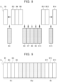
- the battery blocks B2, B6 to B10, and B13 are identified as being the object of replacement (see shaded portions in the FIG. 5 ), for example, these battery blocks B2, B6 to B10, and B 13 are removed from the battery pack 1 to be replaced by the replacement battery blocks Brp, following the battery pack 1 being removed from the vehicle V.
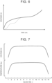
- the replacement battery blocks Brp have been refreshed by being discharged to the final voltage in advance and then charged, and as indicated by the continuous line in FIG. 6 , the memory effect substantially does not occur. That is to say, when the battery blocks B in the battery pack 1 are replaced, the memory effect is not imparted to the replacement battery blocks Brp.
- non-replacement battery blocks B1, B3 to B5, B11, B12, and B14 (hereinafter, referred to as "non-replacement battery blocks Bx" as appropriate, see FIG. 9 ), which are battery blocks B in FIG. 5 that are not the object of replacement, exhibit the memory effect occurring as indicated by the dashed line in FIG. 6 , and when the SOC declines without being refreshed, the voltage declines during discharging due to the memory effect. Further, as shown in FIG. 7 , the temperature of the stacked battery blocks B1 to B14, i.e., the battery blocks B3 to B12 arrayed in a middle region of the battery stack S, becomes generally constant at a relatively high temperature.
- the heat dissipation is higher at both end portions of the battery stack S than at the middle thereof, and accordingly the temperature of the battery blocks B gradually decreases from a middle side toward the battery block B1 on the one end side, and also the temperature gradually decreases from a middle side toward the battery block B14 on the other end side, as shown in FIG. 7 .
- temperature difference occurs between two adjacent battery blocks B n and B n+1 (between B1 and B2, between B2 and B3, between B12 and B13, and between B13 and B14), and voltage difference occurs between these two battery blocks B n and B n+1 due to the temperature difference, as shown in FIG. 7 .
- the replacement battery block Brp will be adjacent to the non-replacement battery blocks B1 and B3 at one end side of the battery stack S in which the above temperature difference occurs, and the replacement battery block Brp will be adjacent to the non-replacement battery blocks B12 and B14 at the other end side.
- the voltage difference between the replacement battery block Brp and the non-replacement battery blocks B1 and B3, and between the replacement battery block Brp and the non-replacement battery blocks B12 and B14 may be great. Therefore, there is a possibility that the ECU 10 of the vehicle V will determine that the battery blocks B need to be replaced again at a relatively early timing after replacement of the battery blocks B.
- the battery blocks B2 and so forth are replaced with the replacement battery blocks Brp as follows. That is to say, as illustrated in FIG. 8 , when the battery blocks B2, B6 to B10, and B13 are removed from the battery pack 1, the non-replacement battery blocks B3 to B5, B11, and B12, other than the non-replacement battery blocks B1 and B14 located at one end or the other end of the battery stack S, are rearranged so as to be collected closer to the one end and the other end of the battery stack S in the stacking direction.
- the non-replacement battery blocks B3 to B5 are moved to the non-replacement battery block B1 side (one end side) with the same array thereof maintained.
- the non-replacement battery blocks B11 and B12 are moved to the non-replacement battery block B14 side (other end side) with the same array thereof maintained.
- multiple (seven) replacement battery blocks Brp are arrayed (assembled) between the multiple non-replacement battery blocks B1 and B3 to B5 on the one end side and the multiple non-replacement battery blocks B11, B12, and B14 on the other end side (the position at which the battery blocks B5 to B 11 were placed before replacement).
- the battery pack 1 when some of the battery blocks B1 to B14 should be replaced, the some (multiple) of the battery blocks B are replaced with replacement battery blocks Brp that are refreshed in advance. That is to say, when battery blocks B in the battery pack 1 are replaced, the memory effect is not imparted to the replacement battery blocks Brp, and the work complication and increase in costs can be suppressed by omitting the process of imparting the memory effect.
- the multiple non-replacement battery blocks Bx in which the memory effect is occurring are appropriately rearranged to be adjacent to each other in the stacking direction of the battery blocks B, and the replacement battery blocks Brp with substantially no memory effect occurring are adjacent to each other in the stacking direction.
- multiple battery blocks B having a similar amount of voltage drop due to the memory effect are grouped together, and accordingly, a situation in which the voltage difference between two adjacent battery blocks B n and B n+1 becomes great due to the voltage drop resulting from the memory effect when the SOC is low after the replacement of the battery blocks B can be satisfactorily suppressed, and whether the battery blocks B need to be replaced can be determined with good precision based on the voltage difference.
- the battery pack 1 a situation in which the battery blocks B are erroneously determined to need to be replaced again at a relatively early timing after the replacement can be suppressed, while suppressing complication and increase in costs of replacement work of the battery blocks B.
- multiple non-replacement battery blocks Bx are adjacent to each other in the stacking direction at the one end side and the other end side of the battery stack S (multiple battery blocks B1 to B14) in the stacking direction, and multiple replacement battery blocks Brp are adjacent to each other in the stacking direction between the multiple non-replacement battery blocks Bx on the one end side and the multiple non-replacement battery blocks Bx on the other end side, as illustrated in FIG. 9 .
- the factors causing the voltage difference to occur between the two adjacent non-replacement battery blocks Bx are substantially reduced to just the temperature difference between the two, thereby satisfactorily suppressing the voltage difference from becoming great, and also non-replacement battery blocks Bx and replacement battery blocks Brp are placed adjacently in a region where the temperature change is small (the range from the battery blocks B3 to B 12 in the present embodiment) and the voltage difference between the two can be satisfactorily suppressed from becoming great.
- the non-replacement battery blocks Bx are placed on one end side and the other end side of the battery stack S where heat dissipation is high, the decline in the SOC of the non-replacement battery blocks Bx due to temperature rise can be suppressed, and the non-replacement battery blocks Bx can be protected.
- the non-replacement battery blocks Bx are arrayed being collected closer to the one end and the other end of the battery stack S (battery blocks B1 to B 14) in the stacking direction. Accordingly, when two or more of the battery blocks B are replaced with the replacement battery blocks Brp (after replacement), the non-replacement battery blocks Bx are placed at or near the positions of original placement, and accordingly, the voltage drop amounts of the non-replacement battery blocks Bx due to the memory effect can be made even closer to each other at each of the one end side and the other end side of the battery stack S.
- the vehicle V that is equipped with the battery pack 1 includes the motor generator MG that exchanges electric power with the battery pack 1, and the ECU 10 that issues a warning when the voltage difference dV n of two adjacent battery blocks B n and B n+1 is not less than the threshold value dVref that is set in advance. Accordingly, the user of the vehicle V can be appropriately and promptly notified that some of the battery blocks B of the battery pack 1 should be replaced.
- the battery pack 1 is not limited to being installed in the vehicle V, and may be installed in, for example, construction equipment, ships, or the like, or may be installed in fixed facilities other than moving bodies.
- the battery blocks B to be replaced with the replacement battery blocks Brp are the battery blocks B regarding which determination is made in the routine shown in FIG. 4 that the voltage difference ⁇ V n between the maximum voltage V max of the battery blocks B 1 to B 14 and the voltage V of the battery blocks B is not less than the threshold value Vref that is set in advance.
- the battery blocks B that should be replaced can be decided more appropriately.
- the user may be recommended to replace the entire battery pack 1 instead of replacing the battery blocks B.
- the battery blocks B and the replacement battery blocks Brp each include, but are not limited to, the battery cells that are nickel metal hydride secondary batteries. That is to say, the battery blocks B and the replacement battery blocks Brp may include battery cells that are other than nickel metal hydride secondary batteries and in which the memory effect occurs. Further, in the above embodiment, the battery blocks B are formed of two battery modules M, but is not limited thereto. That is to say, the battery blocks B may be formed of a single battery module M including a plurality of battery cells, or may be formed of a single battery cell.
- the invention according to the present disclosure is applicable in the battery pack manufacturing industry and so forth.
Abstract
A battery pack (1) according to the present disclosure includes a plurality of battery blocks (B1 to B 14), the battery blocks (B1 to B 14) being arrayed adjacent to each other in a stacking direction that is set in advance. After two or more of the battery blocks (B1 to B14) are replaced with multiple replacement battery blocks (Brp) that have been refreshed in advance, multiple non-replacement battery blocks (Bx), among the battery blocks (B1 to B 14), that have not been replaced with the replacement battery blocks (Brp), are adjacent to each other in the stacking direction, and the replacement battery blocks (Brp) are adjacent to each other in the stacking direction.
Description
- The present disclosure relates to a battery pack including multiple battery blocks arrayed adjacent to each other in a predetermined stacking direction, a vehicle equipped with the battery pack, and a replacement method of the battery blocks in the battery pack.
- Assembled batteries are known that are configured with a plurality of battery modules electrically connected in series or in parallel, the battery modules including a plurality of cells. Each battery module can be replaced with a replacement battery module (e.g., see
Japanese Unexamined Patent Application Publication No. 2003-346909 JP 2003- 346909 A - However, when imparting the memory effect to the replacement battery module in advance, the replacement work of the battery module becomes complicated due to the addition of the process of imparting the memory effect, which may lead to an increase in costs. On the other hand, when the battery module that is an object of replacement is replaced with a replacement battery module to which the memory effect is not imparted in advance, voltage difference between the replacement battery module and an adjacent non-replacement battery module due to having and not having the memory effect becomes great when the state of charge (SOC) is low, and determination may be erroneously made that the battery module needs to be replaced again, immediately after replacing the battery module.
- Accordingly, the present disclosure provides a battery pack, a vehicle equipped with the battery pack and a replacement method of the battery blocks in the battery pack that suppresses erroneous determination that the battery block needs to be replaced again at a relatively early timing after the replacement of the battery block, while suppressing complication and increase in costs of replacement work of a battery block included in the battery pack.
- The battery pack according to a first aspect of the present disclosure is a battery pack including a plurality of battery blocks, the battery blocks being arrayed adjacent to each other in a stacking direction that is set in advance. After two or more of the battery blocks are replaced with multiple replacement battery blocks that have been refreshed in advance, multiple non-replacement battery blocks, among the battery blocks, that have not been replaced with the replacement battery blocks, are adjacent to each other in the stacking direction, and the replacement battery blocks are adjacent to each other in the stacking direction.
- In the battery pack according to the first aspect of the present disclosure, when two or more of the battery blocks should be replaced, the two or more of the battery blocks are replaced with replacement battery blocks that have been refreshed in advance. That is to say, when battery blocks in the battery pack according to the first aspect of the present disclosure are replaced, the memory effect is not imparted to the replacement battery blocks, and work complication and increase in costs can be suppressed by omitting the process of imparting the memory effect. Also, in the battery pack according to the first aspect of the present disclosure, after the battery blocks that are the object of replacement are replaced with the replacement battery blocks, the multiple non-replacement battery blocks in which the memory effect is occurring are appropriately rearranged to be adjacent to each other in the stacking direction, and the replacement battery blocks in which substantially no memory effect is occurring are adjacent to each other in the stacking direction. Accordingly, multiple battery blocks having a similar amount of voltage drop due to the memory effect are grouped together, and thus, a situation in which the voltage difference between two adjacent battery blocks becomes great due to the voltage drop resulting from the memory effect after the replacement of the battery blocks can be satisfactorily suppressed, and whether the battery blocks need to be replaced can be determined with good precision based on the voltage difference. As a result, in the battery pack according to the first aspect of the present disclosure, a situation in which the battery blocks are erroneously determined to need to be replaced again at a relatively early timing after the replacement thereof can be suppressed, while suppressing complication and increase in costs of replacement work of the battery blocks. Note that the battery blocks of the battery pack according to the first aspect of the present disclosure may each be a battery module including a plurality of battery cells, or may include a plurality of the battery modules, or may be a single battery cell.
- Also, after two or more of the battery blocks are replaced with the replacement battery blocks, the non-replacement battery blocks may be adjacent to each other in the stacking direction on both a first end portion side and a second end portion side in the stacking direction, and the replacement battery blocks may be adjacent to each other in the stacking direction between the non-replacement battery blocks on the first end portion side and the non-replacement battery blocks on the second end portion side. In a middle region in the stacking direction of the battery blocks, the temperature of the battery blocks is generally constant at a relatively high temperature, whereas at the first end portion side and the second end portion side of the battery blocks in the stacking direction at which the heat dissipation is high, the temperature of the battery blocks gradually decreases from the middle side toward the ends. Further, when temperature difference occurs between two adjacent battery blocks, voltage difference occurs between the two battery blocks due to the temperature difference. Accordingly, when non-replacement battery blocks and replacement battery blocks are adjacent to each other on the first end portion side and the second end portion side of the battery blocks, the voltage difference between the two may become great due to the difference in having and not having the memory effect, and the temperature difference. Taking this into consideration, in the battery pack according to the first aspect of the present disclosure, the non-replacement battery blocks in which the memory effect has occurred may be arrayed on both the first end portion side and the second end portion side of the battery blocks, and the replacement battery blocks may be arrayed between the non-replacement battery blocks on the first end portion side and the non-replacement battery blocks on the second end portion side. Accordingly, the factors causing the voltage difference to occur between the two adjacent non-replacement battery blocks are substantially reduced to just the temperature difference between the two, thereby satisfactorily suppressing the voltage difference from becoming great, and also non-replacement battery blocks and replacement battery blocks are placed adjacently in a region where the temperature change is small and voltage difference between the two can be satisfactorily suppressed from becoming great.
- Further, among the non-replacement battery blocks, the non-replacement battery blocks that are closer to a first end portion than to a second end portion in the stacking direction may be arrayed being collected to the first end portion, and the non-replacement battery blocks that are closer to the second end portion than to the first end portion may be arrayed being collected to the second end portion. Accordingly, after two or more of the battery blocks are replaced with the replacement battery blocks, the non-replacement battery blocks are placed at or near the positions of original placement of the battery blocks, and accordingly, the voltage drop amounts of the non-replacement battery blocks due to the memory effect can be made even closer to each other at each of the first end portion side and the second end portion side of the battery blocks.
- Further, the battery pack may be configured to be installed in a vehicle, and the vehicle may include an electric motor configured to exchange electric power with the battery pack, and a control device configured to issue a warning when a voltage difference between two of the battery blocks adjacent to each other is not less than a threshold value that is set in advance. Accordingly, a user of the vehicle can be appropriately and promptly notified that some of the battery blocks of the battery pack should be replaced.
- Further, a voltage difference between each of voltages of the battery blocks to be replaced with the replacement battery blocks and a maximum voltage among voltages of the battery blocks may not be less than a replacement threshold value that is set in advance. Thus, the battery blocks that should be replaced can be identified more appropriately.
- Also, each of the battery blocks may include a plurality of nickel metal hydride battery cells and each of the replacement battery blocks may include a plurality of nickel metal hydride battery cells. However, the battery blocks and the replacement battery blocks are not limited to those including nickel metal hydride battery cells, and may include battery cells that are other than the nickel metal hydride battery cells and in which the memory effect occurs.
- A vehicle according to a second aspect of the present disclosure may be equipped with the battery pack, and may include an electric motor configured to exchange electric power with the battery pack, and a control device configured to issue a warning when a voltage difference between two of the battery blocks adjacent to each other is not less than a threshold value that is set in advance. Accordingly, a user of the vehicle can be appropriately and promptly notified that some of the battery blocks of the battery pack should be replaced.
- A replacement method according to a third aspect of the present disclosure is a replacement method of two or more of battery blocks in a battery pack including the battery blocks arrayed adjacent to each other in a stacking direction that is set in advance. The replacement method includes replacing two or more of the battery blocks with multiple replacement battery blocks that have been refreshed in advance, such that, among the battery blocks, multiple non-replacement battery blocks that have not been replaced with the replacement battery blocks are arrayed adjacent to each other in the stacking direction, and the replacement battery blocks are arrayed adjacent to each other in the stacking direction.
- According to this method, a situation in which the battery blocks are erroneously determined to need to be replaced again at a relatively early timing after the replacement can be suppressed, while suppressing complication and increase in costs of replacement work of the battery blocks.
- Also, in the replacement method according to the third aspect of the present disclosure, after two or more of the battery blocks are replaced with the replacement battery blocks, the non-replacement battery blocks and the replacement battery blocks may be arrayed such that the non-replacement battery blocks are adjacent to each other in the stacking direction on both a first end portion side and a second end portion side in the stacking direction, and the replacement battery blocks are adjacent to each other in the stacking direction between the non-replacement battery blocks on the first end portion side and the non-replacement battery blocks on the second end portion side. Accordingly, the factors causing the voltage difference to occur between the two adjacent non-replacement battery blocks are substantially reduced to just the temperature difference between the two, thereby satisfactorily suppressing the voltage difference from becoming great, and also non-replacement battery blocks and replacement battery blocks are placed adjacently in a region where the temperature change is small and voltage difference between the two can be satisfactorily suppressed from becoming great.
- In the replacement method according to the third aspect of the present disclosure, among the non-replacement battery blocks, the non-replacement battery blocks that are closer to a first end portion than to a second end portion in the stacking direction may be arrayed being collected to the first end portion, and the non-replacement battery blocks that are closer to the second end portion than to the first end portion may be arrayed being collected to the second end portion. Accordingly, after two or more of the battery blocks are replaced with the replacement battery blocks, the non-replacement battery blocks are placed at or near the positions of original placement of the battery blocks, and thus, the voltage drop amounts of the non-replacement battery blocks due to the memory effect can be made even closer to each other at each of the first end portion side and the second end portion side of the battery blocks.
- In the replacement method according to the third aspect of the present disclosure, the battery pack may be configured to be installed in a vehicle, and the vehicle may include an electric motor configured to exchange electric power with the battery pack, and a control device configured to issue a warning when a voltage difference between two of the battery blocks adjacent to each other is not less than a threshold value that is set in advance. Accordingly, a user of the vehicle can be appropriately and promptly notified that some of the battery blocks of the battery pack should be replaced.
- In the replacement method according to the third aspect of the present disclosure, a voltage difference between each of voltages of the battery blocks to be replaced with the replacement battery blocks and a maximum voltage among voltages of the battery blocks, may not be less than a replacement threshold value that is set in advance. Thus, the battery blocks that should be replaced can be identified more appropriately.
- In the replacement method according to the third aspect of the present disclosure, each of the battery blocks may include a plurality of nickel metal hydride battery cells and each of the replacement battery blocks may include a plurality of nickel metal hydride battery cells. However, the battery blocks and the replacement battery blocks are not limited to those including nickel metal hydride battery cells, and may include battery cells that are other than the nickel metal hydride battery cell and in which the memory effect occurs.
- Features, advantages, and technical and industrial significance of exemplary embodiments of the invention will be described below with reference to the accompanying drawings, in which like signs denote like elements, and wherein:
-
FIG. 1 is a schematic configuration diagram illustrating a vehicle equipped with a battery pack according to the present disclosure; -
FIG. 2 is a schematic configuration diagram illustrating the battery pack according to the present disclosure; -
FIG. 3 is a flowchart exemplarily showing a routine executed by a control device of the vehicle illustrated inFIG. 1 to determine necessity of replacement of a battery block included in the battery pack according to the present disclosure; -
FIG. 4 is a flowchart exemplarily showing a routine executed to identify a battery block that is an object of replacement in the battery pack according to the present disclosure; -
FIG. 5 is a schematic diagram for describing procedures for replacing a battery block in the battery pack according to the present disclosure; -
FIG. 6 is an explanatory diagram showing voltage characteristics of a non-replacement battery block and a replacement battery block in the battery pack according to the present disclosure. -
FIG. 7 is an explanatory diagram showing temperatures and voltages of a plurality of battery blocks of the battery pack according to the present disclosure; -
FIG. 8 is a schematic diagram for describing procedures for replacing battery blocks in the battery pack according to the present disclosure; and -
FIG. 9 is a schematic diagram for describing procedures for replacing battery blocks in the battery pack according to the present disclosure. - An embodiment for carrying out the invention according to the present disclosure will be described with reference to the drawings.
-
FIG. 1 is a schematic configuration diagram illustrating a vehicle V equipped with abattery pack 1 according to the present disclosure. The vehicle V illustrated inFIG. 1 is an battery electric vehicle (BEV) or a hybrid electric vehicle (hybrid electric vehicle (HEV) or plug-in hybrid electric vehicle (PHEV)) including, in addition to thebattery pack 1, a motor generator (three-phase alternating current electric motor) MG that is connected to thebattery pack 1 via power control devices (omitted from illustration) including an inverter and so forth, and that is capable of exchanging electric power with thebattery pack 1 to output drive power for traveling and regenerative braking force. In the present embodiment, electric power from thebattery pack 1 is supplied to a compressor or the like of an air conditioner provided in the vehicle V, and is also able to be supplied to auxiliary equipment such as headlights via a direct current (DC)-DC converter that is omitted from illustration. Further, the vehicle V includes an electronic control unit 10 (hereinafter, referred to as "ECU 10") that manages thebattery pack 1. - As illustrated in
FIG. 2 , thebattery pack 1 includes multiple (e.g., 28 in the present embodiment) battery modules M connected in series, for example, abase member 2, and ablower 3. Each battery module M includes a module case that is relatively flat and substantially cuboid, and multiple (e.g., six in the present embodiment) battery cells (unit cells), which are omitted from illustration, connected in series, for example, and housed in the module case. Also, each battery cell included in the battery module M is a nickel metal hydride secondary battery. - The battery modules M are arrayed (stacked) so as to be adjacent to each other in a predetermined stacking direction (a right-left direction in
FIG. 2 ) and are integrated with each other to form a battery stack S. In the present embodiment, the stacking direction of the battery modules M matches a thickness direction (the direction in which the shortest side extends) of the module case. The battery modules M (i.e., the battery stack S) are mounted and fixed upon thebase member 2, and are covered with a cover (omitted from illustration) that is fixed to thebase member 2. - Also, in the
battery pack 1, two battery modules M adjacent to each other form one battery block B1, B2, . . . , B13, or B14, as illustrated inFIG. 2 . That is to say, thebattery pack 1 includes multiple (e.g., 14 in the present embodiment) battery blocks B1 to B14 arrayed so as to be adjacent to each other in the stacking direction. When the performance of any of the battery blocks B1 to B14 declines due to deterioration or the like in thebattery pack 1, the battery blocks B1 to B14 that are an object of replacement can be individually replaced. Note that in the following description, the battery blocks B1 to B14 will be collectively referred to as "battery blocks B" as appropriate. - The
base member 2 of thebattery pack 1 has an air supply passage (omitted from illustration) that opens at one end side of thebase member 2, and a discharge port of theblower 3 is connected to the opening portion of the air supply passage. Theblower 3 is a sirocco fan driven by a brushless motor, for example, and is fixed to thebase member 2 so as to face one end of the battery stack S (battery block B1) with a spacing therebetween, as illustrated inFIG. 2 . Theblower 3 sends air, taken in through an intake duct that is omitted from illustration, through the discharge port and into the air supply passage of thebase member 2. - Further, the battery stack S has a plurality of air passages each communicating with the air supply passage of the
base member 2 and communicating with an exhaust duct that is omitted from illustration. In the present embodiment, each air passage is formed between two adjacent battery modules M. Accordingly, the air from theblower 3 is supplied to the air passages through the air supply passage of thebase member 2, and the air flowing into each air passage draws heat away from the battery modules M on both sides and is externally discharged from the exhaust duct that is omitted from illustration. Note that a junction box or the like, omitted from illustration, is placed between the battery stack S (battery block B1) and theblower 3. - In the vehicle V equipped with the
battery pack 1 such as described above, a routine shown inFIG. 3 is repeatedly executed by theECU 10 while the vehicle V is system-activated, in order to determine whether the battery blocks B1 to B14 need to be replaced. When the execution timing of the routine ofFIG. 3 arrives, theECU 10 acquires a voltage (inter-block voltage) Vn (in which "n" is the No. of the battery block B, and n = 1, 2, . . . , 14 in the present embodiment) of each of the battery blocks B1 to B14 detected by a voltage sensor that is omitted from illustration (step S100). Next, theECU 10 sets a variable n, i.e., the No. of the battery blocks B included in thebattery pack 1 to the value 1 (step S110). Further, theECU 10 calculates a voltage difference dVn (= Vn+i - Vn) between the battery block Bn and the battery block Bn+1, from the voltage Vn of the battery block Bn and the voltage Vn+1 of the battery block Bn+1 acquired in step S100 (step S120), and determines whether an absolute value of the voltage difference dVn is not less than a threshold value (positive value) dVref that is set in advance (step S130). - When determination is made that the absolute value of the voltage difference dVn is not less than the threshold value dVref (YES in step S130), the
ECU 10 increments a counter C (step S140), and thereafter determines whether the counter C is not less than a threshold value Cref (aninteger 2 or greater) that is set in advance (step S150). When the counter C is not less than the threshold value Cref (YES in step S150), the voltage difference dVn between the battery block Bn and the battery block Bn+1 is continuously not less than the threshold value dVref, and accordingly theECU 10 deems that the battery block Bn or the battery block Bn+1 of which the voltage Vn or Vn+1 is smaller should be replaced, and the No. n or n+1 thereof is stored in a storage device that is omitted from illustration (step S160). Further, theECU 10 lights a warning light that is omitted from illustration, provided on an instrument panel that is also omitted from illustration, in the vehicle V, in order to notify a user of the vehicle V that there is a battery block B that should be replaced (step S170). - Also, when the
ECU 10 determines that the absolute value of the voltage difference dVn is less than the threshold value dVref (NO in step S130), the processing of steps S140 to S170 is skipped, and when determining that the counter C is less than the threshold value Cref (NO in step S150), the processing of steps S160 to 180 is skipped. After performing the processing of steps S130, S150 or S170, theECU 10 increments the variable n (step S180), and determines whether the variable n is equal to the total number N of the battery blocks B1 to B14 (e.g., 14 in the present embodiment) in the battery pack 1 (step S190). When determining that the variable n is not equal to the total number N (NO in step S190), theECU 10 repeatedly executes the processing of step S120 and thereafter described above, and at the point that the variable n is equal to the total number N (YES in step S190), the routine shown inFIG. 3 is ended for the time being. By executing the routine ofFIG. 3 , the user of the vehicle V can be appropriately and promptly notified that some of the battery blocks B of thebattery pack 1 should be replaced. - Next, procedures for replacing the battery blocks B in the
battery pack 1 will be described with reference toFIGS. 4 to 9 .FIG. 4 is a flowchart exemplarily showing a routine executed for identifying battery blocks B that are an object of replacement, from among the battery blocks B1 to B14 of thebattery pack 1. The routine shown inFIG. 4 is executed by a diagnostic device (computer) connected to the vehicle V at a dealer, a service garage, or the like, to which the vehicle V is brought in. - At the start of the routine shown in
FIG. 4 , the diagnostic device first discharges each battery cell of thebattery pack 1, by operating the air conditioner (omitted from illustration) of the vehicle V, and also turning on headlights, or the like (step S200). The discharging processing in step S200 is executed until an amount of time that is set in advance elapses after the SOC of one of the battery cells declines to a value set in advance. After the discharging processing is completed, the diagnostic device acquires each voltage (inter-block voltage) Vn of the battery blocks B1 to B14 detected by the voltage sensor that is omitted from illustration (step S210). Further, the diagnostic device acquires a maximum voltage Vmax, which is the maximum value among the voltages V1, V2, . . . , V14 acquired in step S210 (step S220). - Next, the diagnostic device sets the variable n (the No. of the battery blocks B) to the value 1 (step S230). Further, the diagnostic device calculates a voltage difference ΔVn (= Vmax - Vn) between the voltage Vn of the battery block Bn acquired in step S210 and the maximum voltage Vmax (step S240), and determines whether the voltage difference ΔVn is not less than a replacement threshold value Vref (positive value) that is set in advance (step S250). When determining that the voltage difference ΔVn is not less than the replacement threshold value Vref (YES in step S250), the diagnostic device deems that the voltage Vn of the battery block Bn has significantly declined due to deterioration or the like, and identifies this battery block Bn as being an object of replacement (step S260). Also, when determining that the voltage difference ΔVn is less than the replacement threshold value Vref (NO in step S250), the
ECU 10 skips the processing of step S260. - After performing the processing of steps S250 or S260, the
ECU 10 increments the variable n (step S270), and determines whether the variable n has exceeded the total number N of the battery blocks B1 to B14 in the battery pack 1 (step S280). When determining that the variable n is not greater than the total number N (NO in step S280), theECU 10 repeatedly executes the processing of step S240 and thereafter described above, and at the point that the variable n exceeds the total number N (YES in step S280), the routine shown inFIG. 4 is ended. By executing the routine shown inFIG. 4 , battery blocks B that should be replaced can be identified more appropriately. - When battery blocks B that are the object of replacement are identified by executing the routine shown in
FIG. 4 , thebattery pack 1 is removed from the vehicle V, and the battery blocks B that are the object of replacement are replaced with replacement battery blocks Brp (seeFIG. 9 ). As illustrated inFIG. 5 , when the battery blocks B2, B6 to B10, and B13 are identified as being the object of replacement (see shaded portions in theFIG. 5 ), for example, these battery blocks B2, B6 to B10, andB 13 are removed from thebattery pack 1 to be replaced by the replacement battery blocks Brp, following thebattery pack 1 being removed from the vehicle V. In the present embodiment, the replacement battery blocks Brp have been refreshed by being discharged to the final voltage in advance and then charged, and as indicated by the continuous line inFIG. 6 , the memory effect substantially does not occur. That is to say, when the battery blocks B in thebattery pack 1 are replaced, the memory effect is not imparted to the replacement battery blocks Brp. - Here, the non-replacement battery blocks B1, B3 to B5, B11, B12, and B14 (hereinafter, referred to as "non-replacement battery blocks Bx" as appropriate, see
FIG. 9 ), which are battery blocks B inFIG. 5 that are not the object of replacement, exhibit the memory effect occurring as indicated by the dashed line inFIG. 6 , and when the SOC declines without being refreshed, the voltage declines during discharging due to the memory effect. Further, as shown inFIG. 7 , the temperature of the stacked battery blocks B1 to B14, i.e., the battery blocks B3 to B12 arrayed in a middle region of the battery stack S, becomes generally constant at a relatively high temperature. On the other hand, the heat dissipation is higher at both end portions of the battery stack S than at the middle thereof, and accordingly the temperature of the battery blocks B gradually decreases from a middle side toward the battery block B1 on the one end side, and also the temperature gradually decreases from a middle side toward the battery block B14 on the other end side, as shown inFIG. 7 . As a result, at both end portions of the battery stack S, temperature difference occurs between two adjacent battery blocks Bn and Bn+1 (between B1 and B2, between B2 and B3, between B12 and B13, and between B13 and B14), and voltage difference occurs between these two battery blocks Bn and Bn+1 due to the temperature difference, as shown inFIG. 7 . - Accordingly, when the battery blocks B2 and B13 become the object of replacement and the battery blocks B2 and B13 are replaced with the replacement battery blocks Brp as exemplarily illustrated in
FIG. 5 , the replacement battery block Brp will be adjacent to the non-replacement battery blocks B1 and B3 at one end side of the battery stack S in which the above temperature difference occurs, and the replacement battery block Brp will be adjacent to the non-replacement battery blocks B12 and B14 at the other end side. In this case, due to both the difference in having and not having the memory effect and the temperature difference, the voltage difference between the replacement battery block Brp and the non-replacement battery blocks B1 and B3, and between the replacement battery block Brp and the non-replacement battery blocks B12 and B14 may be great. Therefore, there is a possibility that theECU 10 of the vehicle V will determine that the battery blocks B need to be replaced again at a relatively early timing after replacement of the battery blocks B. - Taking this into consideration, when the battery blocks B2, B6 to
B 10, and B13 are identified as being the object of replacement as exemplarily illustrated inFIG. 5 , the battery blocks B2 and so forth are replaced with the replacement battery blocks Brp as follows. That is to say, as illustrated inFIG. 8 , when the battery blocks B2, B6 to B10, and B13 are removed from thebattery pack 1, the non-replacement battery blocks B3 to B5, B11, and B12, other than the non-replacement battery blocks B1 and B14 located at one end or the other end of the battery stack S, are rearranged so as to be collected closer to the one end and the other end of the battery stack S in the stacking direction. More specifically, the non-replacement battery blocks B3 to B5 are moved to the non-replacement battery block B1 side (one end side) with the same array thereof maintained. Also, the non-replacement battery blocks B11 and B12 are moved to the non-replacement battery block B14 side (other end side) with the same array thereof maintained. Then, as illustrated inFIG. 9 , multiple (seven) replacement battery blocks Brp are arrayed (assembled) between the multiple non-replacement battery blocks B1 and B3 to B5 on the one end side and the multiple non-replacement battery blocks B11, B12, and B14 on the other end side (the position at which the battery blocks B5 toB 11 were placed before replacement). - As described above, in the
battery pack 1, when some of the battery blocks B1 to B14 should be replaced, the some (multiple) of the battery blocks B are replaced with replacement battery blocks Brp that are refreshed in advance. That is to say, when battery blocks B in thebattery pack 1 are replaced, the memory effect is not imparted to the replacement battery blocks Brp, and the work complication and increase in costs can be suppressed by omitting the process of imparting the memory effect. - Also, in the
battery pack 1, when the battery blocks B that are the object of replacement are replaced with the replacement battery blocks Brp (after replacement), the multiple non-replacement battery blocks Bx in which the memory effect is occurring are appropriately rearranged to be adjacent to each other in the stacking direction of the battery blocks B, and the replacement battery blocks Brp with substantially no memory effect occurring are adjacent to each other in the stacking direction. Accordingly, multiple battery blocks B having a similar amount of voltage drop due to the memory effect are grouped together, and accordingly, a situation in which the voltage difference between two adjacent battery blocks Bn and Bn+1 becomes great due to the voltage drop resulting from the memory effect when the SOC is low after the replacement of the battery blocks B can be satisfactorily suppressed, and whether the battery blocks B need to be replaced can be determined with good precision based on the voltage difference. As a result, in thebattery pack 1, a situation in which the battery blocks B are erroneously determined to need to be replaced again at a relatively early timing after the replacement can be suppressed, while suppressing complication and increase in costs of replacement work of the battery blocks B. - Further, in the
battery pack 1, when two or more of the battery blocks B are replaced with the replacement battery blocks Brp (after replacement), multiple non-replacement battery blocks Bx are adjacent to each other in the stacking direction at the one end side and the other end side of the battery stack S (multiple battery blocks B1 to B14) in the stacking direction, and multiple replacement battery blocks Brp are adjacent to each other in the stacking direction between the multiple non-replacement battery blocks Bx on the one end side and the multiple non-replacement battery blocks Bx on the other end side, as illustrated inFIG. 9 . As a result, the factors causing the voltage difference to occur between the two adjacent non-replacement battery blocks Bx are substantially reduced to just the temperature difference between the two, thereby satisfactorily suppressing the voltage difference from becoming great, and also non-replacement battery blocks Bx and replacement battery blocks Brp are placed adjacently in a region where the temperature change is small (the range from the battery blocks B3 toB 12 in the present embodiment) and the voltage difference between the two can be satisfactorily suppressed from becoming great. In addition, by placing the non-replacement battery blocks Bx on one end side and the other end side of the battery stack S where heat dissipation is high, the decline in the SOC of the non-replacement battery blocks Bx due to temperature rise can be suppressed, and the non-replacement battery blocks Bx can be protected. - Further, in the
battery pack 1, when battery blocks B are replaced, the non-replacement battery blocks Bx are arrayed being collected closer to the one end and the other end of the battery stack S (battery blocks B1 to B 14) in the stacking direction. Accordingly, when two or more of the battery blocks B are replaced with the replacement battery blocks Brp (after replacement), the non-replacement battery blocks Bx are placed at or near the positions of original placement, and accordingly, the voltage drop amounts of the non-replacement battery blocks Bx due to the memory effect can be made even closer to each other at each of the one end side and the other end side of the battery stack S. - Moreover, the vehicle V that is equipped with the
battery pack 1 includes the motor generator MG that exchanges electric power with thebattery pack 1, and theECU 10 that issues a warning when the voltage difference dVn of two adjacent battery blocks Bn and Bn+1 is not less than the threshold value dVref that is set in advance. Accordingly, the user of the vehicle V can be appropriately and promptly notified that some of the battery blocks B of thebattery pack 1 should be replaced. Note however, that thebattery pack 1 is not limited to being installed in the vehicle V, and may be installed in, for example, construction equipment, ships, or the like, or may be installed in fixed facilities other than moving bodies. - Further, in the above embodiment, the battery blocks B to be replaced with the replacement battery blocks Brp are the battery blocks B regarding which determination is made in the routine shown in
FIG. 4 that the voltage difference ΔVn between the maximum voltage Vmax of the battery blocksB 1 toB 14 and the voltage V of the battery blocks B is not less than the threshold value Vref that is set in advance. Thus, the battery blocks B that should be replaced can be decided more appropriately. - When executing the routine shown in
FIG. 4 , determination may be made that only a single battery block Bn should be replaced, and in such a case, there is a possibility that the voltage difference between the replacement battery block Brp replacing this battery block Bn and adjacent battery blocks Bn-1 and Bn+1 will be great. Accordingly, when determination is made in the routine shown inFIG. 4 that only a single battery block Bn should be replaced, at least one or both of the battery blocks Bn-1 and Bn+1 adjacent to the battery block Bn may be selected as being the object of replacement. Further, when the number of non-replacement battery blocks Bx is smaller than the number of battery blocks B placed within the ranges at which the above temperature difference occurs at both end portions of the battery stack S (in the present embodiment, the positions of the battery blocks B1 to B3 and the positions of the battery blocks B12 to B14), which is six in the present embodiment for example, the user may be recommended to replace theentire battery pack 1 instead of replacing the battery blocks B. - Also, in the above embodiment, the battery blocks B and the replacement battery blocks Brp each include, but are not limited to, the battery cells that are nickel metal hydride secondary batteries. That is to say, the battery blocks B and the replacement battery blocks Brp may include battery cells that are other than nickel metal hydride secondary batteries and in which the memory effect occurs. Further, in the above embodiment, the battery blocks B are formed of two battery modules M, but is not limited thereto. That is to say, the battery blocks B may be formed of a single battery module M including a plurality of battery cells, or may be formed of a single battery cell.
- It is needless to say that the invention according to the present disclosure is not limited to the above-described embodiment, and that various modifications can be made within the extent of the scope of the present disclosure. Further, the above embodiment is merely a specific embodiment of the invention described in the SUMMARY OF THE INVENTION, and does not limit the components of the invention described in the
- The invention according to the present disclosure is applicable in the battery pack manufacturing industry and so forth.
Claims (13)
- A battery pack (1) comprising a plurality of battery blocks (B1 to B14), the battery blocks (B1 to B14) being arrayed adjacent to each other in a stacking direction that is set in advance,
wherein, after two or more of the battery blocks (B1 to B14) are replaced with multiple replacement battery blocks (Brp) that have been refreshed in advance, multiple non-replacement battery blocks (Bx), among the battery blocks (B1 to B14), that have not been replaced with the replacement battery blocks (Brp), are adjacent to each other in the stacking direction, and the replacement battery blocks (Brp) are adjacent to each other in the stacking direction. - The battery pack (1) according to claim 1, wherein after two or more of the battery blocks (B1 to B14) are replaced with the replacement battery blocks (Brp), the non-replacement battery blocks (Bx) are adjacent to each other in the stacking direction on both a first end portion side and a second end portion side in the stacking direction, and the replacement battery blocks (Brp) are adjacent to each other in the stacking direction between the non-replacement battery blocks (Bx) on the first end portion side and the non-replacement battery blocks (Bx) on the second end portion side.
- The battery pack (1) according to claim 1 or 2, wherein among the non-replacement battery blocks (Bx), the non-replacement battery blocks (Bx) that are closer to a first end portion than to a second end portion in the stacking direction are arrayed being collected to the first end portion, and the non-replacement battery blocks (Bx) that are closer to the second end portion than to the first end portion are arrayed being collected to the second end portion.
- The battery pack (1) according to any one of claims 1 to 3, wherein the battery pack (1) is configured to be installed in a vehicle (V), the vehicle (V) including an electric motor (MG) configured to exchange electric power with the battery pack (1), and a control device (10) configured to issue a warning when a voltage difference between two of the battery blocks (B1 to B14) adjacent to each other is not less than a threshold value that is set in advance.
- The battery pack (1) according to any one of claims 1 to 4, wherein a voltage difference between each of voltages of the battery blocks (B1 to B14) to be replaced with the replacement battery blocks (Brp) and a maximum voltage among voltages of the battery blocks (B1 to B14) is not less than a replacement threshold value that is set in advance.
- The battery pack (1) according to any one of claims 1 to 5, wherein each of the battery blocks (B1 to B14) includes a plurality of nickel metal hydride battery cells and each of the replacement battery blocks (Brp) includes a plurality of nickel metal hydride battery cells.
- A vehicle (V) equipped with the battery pack (1) according to any one of claims 1 to 3, the vehicle (V) comprising:an electric motor (MG) configured to exchange electric power with the battery pack (1); anda control device (10) configured to issue a warning when a voltage difference between two of the battery blocks (B1 to B14) adjacent to each other is not less than a threshold value that is set in advance.
- A replacement method of two or more of battery blocks (B1 to B14) in a battery pack (1) including the battery blocks (B1 to B14) arrayed adjacent to each other in a stacking direction that is set in advance, the replacement method comprising replacing two or more of the battery blocks (B1 to B14) with multiple replacement battery blocks (Brp) that have been refreshed in advance such that, among the battery blocks (B1 to B14), multiple non-replacement battery blocks (Bx) that have not been replaced with the replacement battery blocks (Brp) are arrayed adjacent to each other in the stacking direction, and the replacement battery blocks (Brp) are arrayed adjacent to each other in the stacking direction.
- The replacement method according to claim 8, wherein after two or more of the battery blocks (B1 to B14) are replaced with the replacement battery blocks (Brp), the non-replacement battery blocks (Bx) and the replacement battery blocks (Brp) are arrayed such that the non-replacement battery blocks (Bx) are adjacent to each other in the stacking direction on both a first end portion side and a second end portion side in the stacking direction, and the replacement battery blocks (Brp) are adjacent to each other in the stacking direction between the non-replacement battery blocks (Bx) on the first end portion side and the non-replacement battery blocks (Bx) on the second end portion side.
- The replacement method according to claim 8 or 9, wherein among the non-replacement battery blocks (Bx), the non-replacement battery blocks (Bx) that are closer to a first end portion than to a second end portion in the stacking direction are arrayed being collected to the first end portion, and the non-replacement battery blocks (Bx) that are closer to the second end portion than to the first end portion are arrayed being collected to the second end portion.
- The replacement method according to any one of claims 8 to 10, wherein the battery pack (1) is configured to be installed in a vehicle (V), the vehicle (V) including an electric motor (MG) configured to exchange electric power with the battery pack (1), and a control device (10) configured to issue a warning when a voltage difference between two of the battery blocks (B1 to B14) adjacent to each other is not less than a threshold value that is set in advance.
- The replacement method according to any one of claims 8 to 11, wherein a voltage difference between each of voltages of the battery blocks (B1 to B14) to be replaced with the replacement battery blocks (Brp) and a maximum voltage among voltages of the battery blocks (B1 to B14), is not less than a replacement threshold value that is set in advance.
- The replacement method according to any one of claims 8 to 12, wherein each of the battery blocks (B1 to B14) includes a plurality of nickel metal hydride battery cells and each of the replacement battery blocks (Brp) includes a plurality of nickel metal hydride battery cells.
Applications Claiming Priority (1)
| Application Number | Priority Date | Filing Date | Title |
|---|---|---|---|
| JP2021122622A JP2023018468A (en) | 2021-07-27 | 2021-07-27 | Battery pack and method for replacing battery block in battery pack |
Publications (1)
| Publication Number | Publication Date |
|---|---|
| EP4138172A2 true EP4138172A2 (en) | 2023-02-22 |
Family
ID=82655337
Family Applications (1)
| Application Number | Title | Priority Date | Filing Date |
|---|---|---|---|
| EP22185477.1A Pending EP4138172A2 (en) | 2021-07-27 | 2022-07-18 | Battery pack, vehicle equipped with battery pack, and replacement method of battery blocks in battery pack |
Country Status (4)
| Country | Link |
|---|---|
| US (1) | US20230033847A1 (en) |
| EP (1) | EP4138172A2 (en) |
| JP (1) | JP2023018468A (en) |
| CN (1) | CN115692986A (en) |
Citations (1)
| Publication number | Priority date | Publication date | Assignee | Title |
|---|---|---|---|---|
| JP2003346909A (en) | 2002-05-30 | 2003-12-05 | Matsushita Electric Ind Co Ltd | Method of replacing secondary battery |
-
2021
- 2021-07-27 JP JP2021122622A patent/JP2023018468A/en active Pending
-
2022
- 2022-07-12 US US17/862,759 patent/US20230033847A1/en active Pending
- 2022-07-14 CN CN202210829553.2A patent/CN115692986A/en active Pending
- 2022-07-18 EP EP22185477.1A patent/EP4138172A2/en active Pending
Patent Citations (1)
| Publication number | Priority date | Publication date | Assignee | Title |
|---|---|---|---|---|
| JP2003346909A (en) | 2002-05-30 | 2003-12-05 | Matsushita Electric Ind Co Ltd | Method of replacing secondary battery |
Also Published As
| Publication number | Publication date |
|---|---|
| US20230033847A1 (en) | 2023-02-02 |
| CN115692986A (en) | 2023-02-03 |
| JP2023018468A (en) | 2023-02-08 |
Similar Documents
| Publication | Publication Date | Title |
|---|---|---|
| US11040624B2 (en) | Cooling strategy for battery systems | |
| JP4117650B2 (en) | Control method for battery power supply | |
| JP4928058B2 (en) | Fluid-cooled battery pack system | |
| US10833376B2 (en) | Battery with life estimation | |
| JP4733668B2 (en) | Battery management system and battery management system driving method | |
| KR101417238B1 (en) | Temperature adjustment structure of electricity storage apparatus | |
| US10059222B2 (en) | Battery temperature estimation system | |
| US20050110460A1 (en) | Battery module having lithium battery, and vehicle control system employing battery module having lithium battery | |
| JP2009021021A (en) | Reconstituted battery pack, method for manufacturing reconstituted battery pack, method for using reconstituted battery pack, and reconstituted battery pack control system | |
| EP4138172A2 (en) | Battery pack, vehicle equipped with battery pack, and replacement method of battery blocks in battery pack | |
| US20230059324A1 (en) | Battery pack | |
| JP7200907B2 (en) | Energy storage stack cooling structure and energy storage stack cooling system | |
| JP2024000155A (en) | Battery management device and battery management method |
Legal Events
| Date | Code | Title | Description |
|---|---|---|---|
| PUAI | Public reference made under article 153(3) epc to a published international application that has entered the european phase |
Free format text: ORIGINAL CODE: 0009012 |
|
| STAA | Information on the status of an ep patent application or granted ep patent |
Free format text: STATUS: REQUEST FOR EXAMINATION WAS MADE |
|
| 17P | Request for examination filed |
Effective date: 20220801 |
|
| AK | Designated contracting states |
Kind code of ref document: A2 Designated state(s): AL AT BE BG CH CY CZ DE DK EE ES FI FR GB GR HR HU IE IS IT LI LT LU LV MC MK MT NL NO PL PT RO RS SE SI SK SM TR |