EP4137983A1 - Systeme und verfahren zum beurteilen von verschlechterung in antriebskomponenten - Google Patents
Systeme und verfahren zum beurteilen von verschlechterung in antriebskomponenten Download PDFInfo
- Publication number
- EP4137983A1 EP4137983A1 EP22175284.3A EP22175284A EP4137983A1 EP 4137983 A1 EP4137983 A1 EP 4137983A1 EP 22175284 A EP22175284 A EP 22175284A EP 4137983 A1 EP4137983 A1 EP 4137983A1
- Authority
- EP
- European Patent Office
- Prior art keywords
- vehicle
- power
- sensor data
- data
- computer system
- Prior art date
- Legal status (The legal status is an assumption and is not a legal conclusion. Google has not performed a legal analysis and makes no representation as to the accuracy of the status listed.)
- Pending
Links
Images






Classifications
-
- G—PHYSICS
- G06—COMPUTING OR CALCULATING; COUNTING
- G06F—ELECTRIC DIGITAL DATA PROCESSING
- G06F30/00—Computer-aided design [CAD]
- G06F30/20—Design optimisation, verification or simulation
- G06F30/27—Design optimisation, verification or simulation using machine learning, e.g. artificial intelligence, neural networks, support vector machines [SVM] or training a model
-
- G—PHYSICS
- G07—CHECKING-DEVICES
- G07C—TIME OR ATTENDANCE REGISTERS; REGISTERING OR INDICATING THE WORKING OF MACHINES; GENERATING RANDOM NUMBERS; VOTING OR LOTTERY APPARATUS; ARRANGEMENTS, SYSTEMS OR APPARATUS FOR CHECKING NOT PROVIDED FOR ELSEWHERE
- G07C5/00—Registering or indicating the working of vehicles
- G07C5/08—Registering or indicating performance data other than driving, working, idle, or waiting time, with or without registering driving, working, idle or waiting time
- G07C5/0808—Diagnosing performance data
-
- G—PHYSICS
- G06—COMPUTING OR CALCULATING; COUNTING
- G06N—COMPUTING ARRANGEMENTS BASED ON SPECIFIC COMPUTATIONAL MODELS
- G06N3/00—Computing arrangements based on biological models
- G06N3/02—Neural networks
- G06N3/08—Learning methods
-
- G—PHYSICS
- G07—CHECKING-DEVICES
- G07C—TIME OR ATTENDANCE REGISTERS; REGISTERING OR INDICATING THE WORKING OF MACHINES; GENERATING RANDOM NUMBERS; VOTING OR LOTTERY APPARATUS; ARRANGEMENTS, SYSTEMS OR APPARATUS FOR CHECKING NOT PROVIDED FOR ELSEWHERE
- G07C5/00—Registering or indicating the working of vehicles
- G07C5/008—Registering or indicating the working of vehicles communicating information to a remotely located station
-
- G—PHYSICS
- G07—CHECKING-DEVICES
- G07C—TIME OR ATTENDANCE REGISTERS; REGISTERING OR INDICATING THE WORKING OF MACHINES; GENERATING RANDOM NUMBERS; VOTING OR LOTTERY APPARATUS; ARRANGEMENTS, SYSTEMS OR APPARATUS FOR CHECKING NOT PROVIDED FOR ELSEWHERE
- G07C5/00—Registering or indicating the working of vehicles
- G07C5/08—Registering or indicating performance data other than driving, working, idle, or waiting time, with or without registering driving, working, idle or waiting time
- G07C5/0841—Registering performance data
- G07C5/085—Registering performance data using electronic data carriers
-
- G—PHYSICS
- G06—COMPUTING OR CALCULATING; COUNTING
- G06F—ELECTRIC DIGITAL DATA PROCESSING
- G06F2119/00—Details relating to the type or aim of the analysis or the optimisation
- G06F2119/02—Reliability analysis or reliability optimisation; Failure analysis, e.g. worst case scenario performance, failure mode and effects analysis [FMEA]
Definitions
- Example embodiments are related to systems and methods for assessing degradation in drive components such as in the field of electric and hybrid vehicles and equipment.
- a drive system for an electric or hybrid vehicle may have an engine (e.g., diesel engine), a generator coupled to the engine, a power conversion system connected to the Direct Current (DC) bus, and a motor.
- the power conversion system electrically couples the DC bus between the generator and the motor and motor drives one or more elements of the vehicle.
- the power conversion system consists of two converters.
- a converter is coupled electrically between the generator and the DC bus and is controlled to convert Alternating Current (AC) power into DC power during generating of the generator and DC power into AC power during motoring of the motor.
- the motor can be a Switched Reluctance (SR) motor, a Permanent Magnet (PM) AC Motor or an Induction AC Motor.
- SR Switched Reluctance
- PM Permanent Magnet
- a power inverter is coupled electrically between the DC bus and the motor and is controlled to convert DC power from the DC bus into AC power during motoring of the motor and to convert AC power into DC power during electric braking of the motor.
- a computer system includes a memory storing instructions and at least one processor configured to executed the instructions to cause the computer system to obtain sensor data, the sensor data corresponding to measurements of at least one component of an electric powertrain system of at least one vehicle and generate a first digital twin based on the obtained sensor data, the first generated twin associated with a type of the at least one vehicle.
- the at least one processor is configured to execute the instructions to cause the computer system to send the first digital twin to the at least one vehicle.
- the at least one processor is configured to execute the instructions to cause the computer system to, send the first digital twin to other vehicles of the same type of the at least one vehicle.
- the at least one processor is configured to execute the instructions to cause the computer system to, obtain additional sensor data; update the first digital twin based on the additional sensor data; and send the updated digital twin to the at least one vehicle.
- the at least one processor is configured to execute the instructions to cause the computer system to, generate a second digital twin based on the additional sensor data, the second digital twin associated with a second type of vehicle, the second type being different than the type of the at least one vehicle.
- the sensor data is data generated from one or more Internet of Things (IoT) sensors coupled to the vehicle.
- IoT Internet of Things
- the sensor data includes temperature measurements, vibration measurements and humidity measurements associated with the at least one component of the electric powertrain system of the vehicle.
- the at least one component is a switching device of an inverter.
- the first digital twin estimates degradation of the switching device.
- the first digital twin uses a deep neural network (DNN).
- DNN deep neural network
- a vehicle in at least one example embodiment, includes an electric powertrain system, a plurality of sensors coupled to the electric powertrain system, the plurality of sensors configured to generate sensor data, the sensor data being measurements of at least one component of the electric powertrain system, a memory storing instructions and at least one processor configured to execute the instructions to cause the vehicle to send the generated measurements to at least one server, and obtain a digital twin associated with the at least one component.
- the at least one processor configured to executed the instructions to cause the vehicle to, send additional sensor data; and receive an updated digital twin based on the additional sensor data.
- the plurality of sensors are Internet of Things (IoT) sensors.
- IoT Internet of Things
- the sensor data includes temperature measurements, vibration measurements and humidity measurements associated with the at least one component.
- the at least one component is a switching device of an inverter.
- the digital twin estimates degradation of the switching device.
- the first digital twin uses a deep neural network (DNN).
- DNN deep neural network
- a vehicle comprises: an electric powertrain system; a plurality of sensors coupled to the electric powertrain system, the plurality of sensors configured to generate sensor data, the sensor data being measurements of at least one component of the electric powertrain system; a memory storing instructions; and at least one processor configured to execute the instructions to cause the vehicle to, send the generated measurements to at least one other vehicle, and obtain a digital twin associated with the at least one component.
- FIGS. 1-7D represent non-limiting, example embodiments as described herein.
- Such existing hardware may be implemented using processing or control circuitry such as, but not limited to, one or more processors, one or more Central Processing Units (CPUs), one or more microcontrollers, one or more arithmetic logic units (ALUs), one or more digital signal processors (DSPs), one or more microcomputers, one or more field programmable gate arrays (FPGAs), one or more System-on-Chips (SoCs), one or more programmable logic units (PLUs), one or more microprocessors, one or more Application Specific Integrated Circuits (ASICs), or any other device or devices capable of responding to and executing instructions in a defined manner.
- processors e.g., data processors and controllers
- CPUs Central Processing Units
- microcontrollers e.g., one or more arithmetic logic units (ALUs), one or more digital signal processors (DSPs), one or more microcomputers, one or more field programmable gate arrays (FPGAs), one or more System-
- the term 'module' may be replaced with the term 'circuit.
- the term 'module' may refer to, be part of, or include processor hardware (shared, dedicated, or group) that executes code and memory hardware (shared, dedicated, or group) that stores code executed by the processor hardware.
- the module may include one or more interface circuits.
- the interface circuits may include wired or wireless interfaces that are connected to a local area network (LAN), the Internet, a wide area network (WAN), or combinations thereof.
- LAN local area network
- WAN wide area network
- the functionality of any given module of the present disclosure may be distributed among multiple modules that are connected via interface circuits.
- At least one embodiment of the invention relates to a non-transitory computer-readable storage medium comprising electronically readable control information stored thereon, configured such that when the storage medium is used in a controller of a motor system, at least one embodiment of the method is carried out.
- any of the aforementioned methods may be embodied in the form of a program.
- the program may be stored on a non-transitory computer readable medium and is adapted to perform any one of the aforementioned methods when run on a computer device (a device including a processor).
- the non-transitory, tangible computer readable medium is adapted to store information and is adapted to interact with a data processing facility or computer device to execute the program of any of the above mentioned embodiments and/or to perform the method of any of the above mentioned embodiments.
- the computer readable medium or storage medium may be a built-in medium installed inside a computer device main body or a removable medium arranged so that it can be separated from the computer device main body.
- the term computer-readable medium, as used herein, does not encompass transitory electrical or electromagnetic signals propagating through a medium (such as on a carrier wave); the term computer-readable medium is therefore considered tangible and non-transitory.
- various information regarding stored images for example, property information, may be stored in any other form, or it may be provided in other ways.
- code may include software, firmware, and/or microcode, and may refer to programs, routines, functions, classes, data structures, and/or objects.
- memory is a subset of the term computer-readable medium.
- computer-readable medium does not encompass transitory electrical or electromagnetic signals propagating through a medium (such as on a carrier wave); the term computer-readable medium is therefore considered tangible and non-transitory.
- Non-limiting examples of the non-transitory computer-readable medium include, but are not limited to, rewriteable non-volatile memory devices (including, for example flash memory devices, erasable programmable read-only memory devices, or a mask read-only memory devices); volatile memory devices (including, for example static random access memory devices or a dynamic random access memory devices); magnetic storage media (including, for example an analog or digital magnetic tape or a hard disk drive); and optical storage media (including, for example a CD, a DVD, or a Blu-ray Disc).
- Examples of the media with a built-in rewriteable non-volatile memory include but are not limited to memory cards; and media with a built-in ROM, including but not limited to ROM cassettes; etc.
- various information regarding stored images for example, property information, may be stored in any other form, or it may be provided in other ways.
- the term data storage device may be used interchangeably with computer-readable medium.
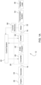
- FIG. 1A illustrates an inverter-fed drive system 12 for an electric or hybrid vehicle to have an engine 20 (e.g., diesel engine), a generator 24 coupled to the engine 20, and a power conversion system 28 coupled electrically between the generator 24 and a motor 32.
- the power conversion system 28 is an electrical link between the generator 24 and motor 32.
- the power conversion system 28 includes the converter 26 and the power inverter 30.
- the engine 20 provides motive power for a vehicle. While not illustrates, a gearbox to convert speed and torque from the engine 20 to the generator 24.
- the generator 24 may take the form of a high-speed three-phase interior-permanent-magnet brushless synchronous generator having three phase windings, or other suitable form.
- the motor 32 may be a switched reluctance (SR) motor, a Permanent Magnet (PM) AC Motor or an Induction AC Motor.
- SR switched reluctance
- PM Permanent Magnet
- the drive system 12 of example embodiments is well suited for diagnosing, identifying and classifying a failure of an inverter (e.g., the power inverter 30) in real-time or during an operational mode of the inverter, as opposed to a pre-test non-operational mode.
- the inverter e.g., the power inverter 30
- the inverter In the operational mode, the inverter (e.g., the power inverter 30) is capable of converting direct current into one or more alternating current signals for application to a machine or motor for control of the machine or motor 32.
- the inverter does not provide or output one or more alternating current signals for application to a machine or motor 32.
- the power conversion system 28 may have a converter 26 coupled electrically between the generator 24 and the motor 32 to convert alternating current (AC) power into DC power during a generation operating mode of the generator 24 (i.e. conversion of mechanical energy from the power source into electric energy for supply onto the power conversion system 28), and DC power into AC power during motoring of the generator 24 (i.e. removing electric energy from the power conversion system 28 and converting it into mechanical energy for the power source).
- the power conversion system 28 may have the power inverter 30 (e.g., a multi-phase inverter) coupled electrically between the converter 26 and the motor 32 to convert DC power from the power conversion system 28 into AC power during motoring of the motor 32 and to convert AC power into DC power during braking of the motor 32.
- the drive system 12 may include a brake chopper 22 to dissipate electric power from the power conversion system 28.
- the power inverter 30 In vehicles with a brake chopper 22 (i.e. regenerative braking), the power inverter 30 also takes power from the motor 32 during braking and stores it in batteries (not shown).
- a conductor 16 (e.g., a AC bus bar) is an AC link between the power inverter 30 and the motor 32.
- Another conductor 16 is an AC link between the converter 26 and the generator 24.
- a voltage sensor 37 (shown in FIG. 1B ) is coupled electrically to the power conversion system 28 to sense a DC bus voltage and output a DC bus voltage signal indicative thereof.
- a group of three current sensors 38 are coupled magnetically to the motor 32 to sense a phase current of the motor 32 and output a phase current signal indicative thereof.
- the current sensors 38 may operate on the principle of magnetic field sensing, such that a realized magnetic coupling allows for an electrical isolation between high-voltage power circuits and low-voltage control circuits.
- a control system 40 is coupled electrically to the voltage sensor 37 and the current sensor 38 to receive signals from the sensors pertaining to system operation.
- the drive system 12 may have a current sensor 38 for each phase of the motor 32.
- the drive system 12 will typically have a plurality of current sensors (e.g., three), each current sensor 38 being coupled magnetically to a respective phase of the motor 32 to sense a respective phase current of the motor 32 and output a respective phase current signal indicative thereof.
- the control system 40 is coupled electrically to each of the current sensors 38. Additionally, it can be appreciated that the drive system 12 can have more than more components than shown in FIG. 1A .
- a transmission system 34 may transfer power from the motor 32 to a traction load 36 (e.g., vehicle wheels).
- the power conversion system 28 has a positive DC power rail (high-side line) 44 and a negative DC power rail (low-side line) 46.
- the nominal voltage of the power conversion system 28 between the positive and negative DC power rails 44, 46 may be, for example, 700 Volts DC. However, it should be understood that the nominal voltage may be greater than or less than 700 volts DC.
- the power converter 26 may be configured as an AC-DC converter to convert three-phase AC power from the generator 24, which may be a 3-phase permanent magnet (PM) generator, into DC power for the power conversion system 28, and vice versa.
- the digital circuit voltages into the power converter 26 for the power generator 24 are denoted as Vdig_1 for the phase 1 voltage, Vdig_2 for phase 2 voltage, and Vdig_3 for phase 3 voltage.
- Vdig_1, Vdig_2 and Vdig_3 For each phase of the voltage, Vdig_1, Vdig_2 and Vdig_3, two switch packages 84 are placed across the DC supply, and are switched on and off to generate the three phases from the motor power converter 26 to the power generator 24.
- Each switch package 84 includes a diode 84-1 and a MOSFET transistor 84-2.
- Respective switch packages 84 may be coupled to a respective one of the generator 24 phase windings to convert AC power from the respective winding into DC power on the power conversion system 28 between the positive DC power rail 44 and the negative DC power rail 46.
- the transistor 84-2 When the appropriate voltage is applied to the gate of an MOSFET transistor 84-2 of the power converter 26, the transistor 84-2 may be activated and the drain may be coupled electrically to the emitter to supply electric power.
- the appropriate voltage depends on a rating of the transistor 84-2. For example, 14 V may be applied at the gate to turn the transistor 84-2 on. Negative 8 V may be applied at the gate with to turn the transistor 84-2 off.
- the power converter 26 may be operated in reverse if the generator 24 is to operate as a motor.
- the high-side switching transistor (e.g., 94-2a) and the low-side switching transistor (e.g., 94-2b) may comprise field effect transistors, complementary metal oxide semiconductors, power transistors, or other suitable semiconductor devices.
- the power converter 26 is controlled by the control system 40.
- a generator controller 48 of the control system 40 may have gate drivers and an analog-to-digital converter (ADC) 50, a microprocessor 52 coupled electrically to the gate drivers 50, and memory 54 coupled electrically to the microprocessor 52 and having stored therein operating instructions for the microprocessor 52.
- the gate of each transistor 84-2 is coupled electrically to a respective gate driver 50 that is dedicated to that transistor 84-2 and may provide a low DC voltage (e.g., 24 VDC) to turn on and off that transistor 84-2.
- a gate driver 50 for each transistor 84-2 of the power converter 26 there may be a gate driver 50 for each transistor 84-2 of the power converter 26.
- the gate drivers 50 for the transistor 84-2 of the power converter 26 are under the control of the microprocessor 52, which may employ a pulse-width-modulation control scheme to control those gate drivers 50 and the transistor 84-2 of the power converter 26 to supply electric energy on the power conversion system 28 in the generating mode of the generator 24 and remove electric energy from the power conversion system 28 in the motoring mode of the generator 24.
- the microprocessor 52 may employ a pulse-width-modulation control scheme to control those gate drivers 50 and the transistor 84-2 of the power converter 26 to supply electric energy on the power conversion system 28 in the generating mode of the generator 24 and remove electric energy from the power conversion system 28 in the motoring mode of the generator 24.
- space vector modulation may be used.
- any known pulse-width-modulation scheme for drive systems may be used. Thus, for the sake of brevity, the pulse-width-modulation scheme will not be described in greater detail.
- the motor 32 may be configured as a three-phase switched reluctance (SR) motor having three phase windings 42a, 42b and 42c, as shown in FIG. 1B , or may be an AC PM or Induction motor (not shown).
- SR switched reluctance
- Each power inverter 30 is coupled electrically between the motor 32 and the rails 44, 46 of the power conversion system 28.
- the power inverter 30 may be configured, for example, as a DC-AC inverter to convert DC power from the power conversion system 28 into three-phase AC power for the motor 32, and vice versa.
- Vdig_phA The digital circuit voltages for each of motor phase windings 42a, 42b and 42c into the power inverter 30 for the motor 32 are denoted as Vdig_phA for the phase A voltage, Vdig_phB for the phase B voltage, and Vdig_phC for the phase C voltage.
- Vdig_phA, Vdig_phB and Vdig_phC For each phase of the voltage, Vdig_phA, Vdig_phB and Vdig_phC, a pair of high-side and low-side switch packages 94a, 94b are placed in series across the DC supply bus, and are switched on and off to generate the power across each phase winding.
- switch states indicate whether a properly functioning or unimpaired semiconductor device is active ("on” or “closed”) or inactive ("off” or “open”).
- a failure of a semiconductor device to change states may result in a semiconductor device failing in an open state or a closed state, for example.
- the power inverter 30 may include pairs of high-side and low-side switch packages 94a and 94b.
- Each high-side switch package 94a includes a diode 94-1a, a transistor 94-2a, and a power diode 96.
- Each low-side switch package 94b includes a diode 94-1b, a transistor 94-2b and a power diode 96. Pairs of switch packages 94a, 94b may be respectively coupled electrically to the motor 32 phase windings, 42a, 42b and 42c. As such, the power inverter 30 is depicted as having three sections, 31a, 31b and 31c, each associated with one of the phase windings 42a, 42b and 42c.
- the sections 31a, 31b and 31c enable individual control of each individual phase A, B and C.
- a high-side switch package 94a and a low-side switch package 94b are connected across a respective motor phase winding 42a, 42b and 42c.
- the high-side switch package 94a is coupled electrically to the positive DC rail 44
- the low-side switch package 94b is coupled electrically to the negative DC rail 46.
- the transistor 94-2a and/or 94-2b switch
- the power inverter 30 may be operated in reverse if the motor 32 is to operate as a generator.
- a motor controller 56 of the control system 40 may have gate drivers 58, a field programmable gate array 60 (FPGA) coupled electrically to the gate drivers 58, a microprocessor (e.g., digital signal processor) 62 coupled electrically to the FPGA 60, and memory 64 coupled electrically to both the FPGA 60 and the microprocessor 62 and having stored therein operating instructions for the FPGA 60 and the microprocessor 62.
- FPGA field programmable gate array 60
- microprocessor e.g., digital signal processor
- each transistor 94-2a, 94-2b is coupled electrically to a respective gate driver 58 that is dedicated to that transistor 94-2a, 94-2b and may provide a low DC voltage (e.g., 24 VDC) to turn on and off that transistor 94-2a, 94-2b.
- a low DC voltage e.g., 24 VDC
- the gate drivers 58 are under the control of the FPGA 60 which may employ a SR-motor control scheme to control the gate drivers 58, the transistor 94-2a, 94-2b, and thus, the motor 32 (including varying the amplitudes and frequencies to the motor windings 42a, 42b, 42c) so as to vary the torque output of the motor 32 when the motor 32 is in its motoring mode or to vary the electric generation capacity of the motor 32 when the motor 32 is in its braking mode.
- a SR-motor control scheme to control the gate drivers 58, the transistor 94-2a, 94-2b, and thus, the motor 32 (including varying the amplitudes and frequencies to the motor windings 42a, 42b, 42c) so as to vary the torque output of the motor 32 when the motor 32 is in its motoring mode or to vary the electric generation capacity of the motor 32 when the motor 32 is in its braking mode.
- the drive system 12 can have more than one motor 32 and attached power inverter 30 and current sensor(s) 38 incorporated therein, and the control system 40 may have a motor controller 56 for each power inverter 30, although only one such power inverter 30 and motor controller 56 is discussed and shown.
- the drive system 12 may include a brake chopper 22 to control use of a power resistor 70 to dissipate electric power from the power conversion system 28.
- the brake chopper 22 may be coupled electrically between the rails 44, 46 as shown.
- the digital circuit voltage into the drive system 12 from the brake chopper 22 is shown as Vdig_Brake.
- the brake chopper 22 may include a switch package 74, with a diode 74-1 and MOSFET transistor 74-2 and a diode 76.
- the diode 76 may be in parallel with the power resistor 70.
- the transistor 74-2 When the appropriate voltage is applied to the gate of the transistor 74-2 of the brake chopper 22, the transistor 74-2 may be activated to allow dissipation of electric power through the power resistor 70.
- the gate driver for the transistor 74-2 of the brake chopper 22 issues a power resistor control signal in the form of, for example, a pulse-width modulated voltage signal that applies the voltage to the base of the switch transistor 74-2, the voltage signal being pulse-width modulated according to a brake duty to turn the power resistor 70 ON, to dissipate electric energy from the power conversion system 28, and OFF correspondingly.
- the brake chopper 22 is controlled by the control system 40.
- the gate driver for the transistor 74-2 of the brake chopper 22 may be one of the gate drivers 58 of the motor controller 56.
- Such gate driver 58 for the transistor 74-2 may be under the control of the FPGA 60 of the motor controller 56 to control that gate driver 58, the transistor 74-2, and the brake resistor 70.
- the gate driver for the transistor 74-2 may be one of the gate drivers 50 of the generator controller 48. In such a case, that gate driver 50 may be under the control of the microprocessor 52 of the generator controller 48 to control that gate driver 50, the transistor 74-2, and the brake resistor 70.
- the drive system 12 may have one or more voltage sensors coupled to the positive DC rail 44 of the power conversion system 28 to sense the DC bus voltage.
- the DC bus voltage is the voltage across the rails 44 and 46.
- voltage sensors are also coupled to the negative DC rail 46 of the power conversion system 28 and configured to sense the phase voltages for phases A, B and C.
- Voltage sensors 36 may be stand-alone sensors or may be incorporated into any of the controllers 48, 56 in the control system.
- one voltage sensor 37 may be for the generator 24 and another voltage sensor 37 may be used for motor control and pole voltage measurements.
- the voltage sensor 37 may send a signal to the control system 40 including the sensed DC bus voltage level.
- the drive system 12 may further include a temperature sensors 41a-41b.
- a temperature sensor 41a senses the temperature of the rotor permanent magnet or magnets.
- the temperature sensor 41a may include one or more sensors located on the stator, in thermal communication with the stator, or secured to the housing of the motor 32.
- the temperature sensor 41a may be or include a thermistor and wireless transmitter like infrared thermal sensor mounted on the rotor or the magnet, where the detector provides a signal (e.g., wireless signal) indicative of the temperature of the magnet or magnets.
- a temperature sensor 42a senses the temperature(s) of the windings of the generator 24.
- the temperature sensors 41-41b are located to detect hot-spot temperatures.
- a specific location of a hot spot may be determined by using available simulation software tools such as ANSYS Fluent and JMAG.
- there may be multiple temperature sensors embedded in body of electric machine e.g., the motor 32 and/or the generator 24.
- Outputs of the current sensors 38, voltage sensor 37, temperature sensors 41a-41b and temperature sensor 43 may be digitized by an ADC 61.
- the output of the ADC 61 is coupled to the microprocessor 62.
- a DC link capacitor 700 may be provided between the rails 44, 46.
- the capacitor 700 may be configured, for example, as a bank of capacitors.
- At least one temperature sensor 43 may measure the temperature inside the DC link capacitor and/or temperatures are points of contacts between the conductor 16 and the DC link capacitor 700.
- windings 42a, 42b and 42c may be replaced with or represent an inductor.
- Other possible feedback data includes, but is not limited to, winding temperature readings, semiconductor temperature readings of the power inverter 30, three phase voltage data, vibration date or other thermal or performance information for the system 12.
- the current sensors 38, voltage sensor 37, temperature sensor 41 and temperature sensor 43 may be internet-of-things (IoT) based sensors.
- the drive system 12 may include IoT vibration sensors located on bolted joints.
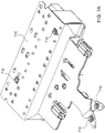
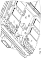
- FIGS. 7A-7D illustrate example embodiments of locations of temperature sensors.
- the structures of an inverter power stage (including a DC bus bar and capacitor bank) shown in FIG. 7A , an SiC power module shown in FIG. 7B , cooling system assembly of the SiC inverter shown in FIG. 7C and a metallic (copper) plate to draw down heat from the SiC power modules' AC terminal is shown in FIG. 7D .
- These parts and features of the SiC inverter are described and illustrated in detail in U.S. Provisional Appln. No. 63/018,501 , the entire contents of which are incorporated by reference.
- FIG. 7A illustrates locations of temperature sensors 710 on an example capacitor bank and DC bus bar.
- FIG. 7B illustrates a location of a temperature sensor 710 near a clamp-on power interconnect 720 between DC terminals of the SiC power module and an inverter DC bus bar 715.
- FIG. 7B also shows a temperature sensor 710 on one of three AC output terminals 725 of the SiC power module.
- FIG. 7C illustrates temperature sensors 710 at an inlet coolant port 730 and a cooling system feature 740 (e.g., coolant channels engraved in the baseplate of the SiC power module).
- FIG.7C also shows temperature sensors 710 at an outlet of a coolant port 750 and a cooling system feature 760 (e.g., coolant channels engraved in the baseplate of the SiC power module).
- one sensor 710 is located near a clamp-on connector 720 of a power module and another sensor 710 is on a bolted joint on an AC terminal 725.
- FIG. 7B illustrates temperature sensors 710 at an inlet coolant port 730 and a cooling system feature 740 (e.g., coolant channels engraved in the baseplate of the SiC power module).
- FIG.7C also shows temperature sensors 710 at an outlet of a coolant port 750 and a cooling system
- FIG. 7C illustrates locations of temperatures sensors 710 on metallic (copper) plate 770 underneath AC terminals of the SiC power module.
- the temperature sensors 710 in FIG. 7D are on a metallic (copper) plate 770 attached with the inverter cooling structure to draw down heat from the SiC power modules' AC terminals. These AC terminals are shown in detail in FIG. 7B .
- the cooper plate 770 works as heat spreader to rapidly draw down heat produced at bolted joints with the AC terminals of the SiC power module ( FIG. 7B ).
- the temperature sensors 710 on the copper plate 770 monitor how heat is spreading vertically and horizontally and to see how at least one bolted joint at SiC power module's AC terminals is degrading with use of the inverter in the vehicle.
- the measurements from the sensors in the systems may be used to develop a degradation model of inverter.
- High-performance heavy-duty off-road vehicles use power converter-fed electric machines (e-machines) (e.g., the motor system of FIG. 1A-1B ) to achieve efficiency in a traction drive system.
- e-machines power converter-fed electric machines
- These e-machines (motor and generator) and other components contain large quantities of copper, aluminum, steel, cast iron, silicon-iron steel (laminations), and plastic, which at the end of their life, result in a large volume of material waste that could lead to a harmful economic and environmental impact.
- the metals and plastic components in the traction drive system are recyclable and can be reclaimed and reused as the secondary feedstock in an eco-friendly re-manufacturing of various vehicle parts. Cost savings can be achieved by reintroducing economically refurbished vehicles with eco-friendly remanufactured parts back into the market.
- components of the power converter-fed electric machines may be considered to have reached their end of life when either solder degradation or an electrical interconnect breakage occurs.
- Other subcomponents, such as the copper baseplate and a copper DC bus bar attached to the power module may have only consumed a fraction of their life.
- copper and aluminum can be reclaimed from the motor used in the vehicle traction drive system. If successfully reclaimed, these metals could have a significant secondary life.
- An electric powertrain system may be a system that transmits a drive from an energy source (e.g., an engine) of a vehicle to an axle using electricity.
- an electric powertrain system may include the electric generator 24, the power converter 26 extracting electrical energy electric generator 24, the DC bus, a second converter (e.g., the power inverter 30), the motor 32, and the transmission system 34, where the power converter 26 is connected to the generator 24, the second converter (e.g., the power inverter 30) is connected with the motor 32, and the motor 32 drives the transmission system 34, which applies a tractive force to the traction load 36.
- At least some example embodiments provide degradation modeling and failure detection of components used in an electric powertrain of heavy-duty off-road vehicles such as the power inverter 30 and motor 32, described in FIGS. 1A-1B .
- degradation modeling and failure detection is based on Artificial Intelligence (AI) and Machine Learning (ML) techniques.
- AI and ML techniques may be used to implement digital twins.
- One sibling of the digital twins executes physical model of the electric drive's critical components and the other sibling of digital twins replicate physical behavior of these components.
- the twin that replicates the physical behavior may be implemented in the cloud.
- the cloud based digital twin may use a Deep Neural Network (DNN) to compute data measured from a vehicle's components that are instrumented with IoT-based sensors (e.g., the current sensors 38, voltage sensor 37, temperature sensor 41 and temperature sensor 43).
- DNN Deep Neural Network
- the degradation modeling and failure detection in accordance with at least some example embodiments will be applicable to remanufacturing of electric powertrains used in electric and hybrid vehicles.
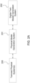
- FIG. 2A illustrates a degradation modeling and failure detection generating system according to an example embodiment.
- the system includes at least one twinned physical system 200, a physical model generation system 201 and a digital twin model generation system.
- the at least one twinned physical system 200 may be one of the components shown in FIGS. 1A-1B (e.g., the power inverter 30).
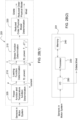
- FIG. 2B(1) illustrates an example embodiment of a physical model generation system 201.
- the computing system obtains sensor outputs from the motor system.
- the system obtains outputs from the current sensors 38, voltage sensor 37, temperature sensor 41 and temperature sensor 43 and a switching rate in the power inverter 30.
- Other sensors that may be used to provide data to 205 may include a distributed temperature sensor for thermal stack-up of switching power devices in the power inverter 30, a temperature sensor inside a DC bus capacitor (including temperature sensors at electrical contact points (also called inverter interconnects) of the DC bus capacitors), a temperature sensor at bolted joints (bolted joints are also inverter interconnects), vibration sensors and humidity sensors (such as at electrical contacts exposed to humidity and on a surface of DC bus capacitors).
- FIG. 2B(1) is illustrated in the context of a motor system, the physical model may be determined for other types of systems having sensors to monitor data of the system.
- the power function and temperature function determination may be performed by a machine intelligence interface system (MIIS).
- MIIS machine intelligence interface system
- the MIIS is a data interface for ground truth generation.
- the MIIS is a data link to the physical degradation model that provides the output from the IoT sensors.
- a power function may refer to a function of power input to a device (e.g, an inverter, a MOSFET, etc.) and/or system.
- An electrical loading function may refer to what fraction of the power function causes power loss that results in temperature change.
- power loss function may be a mechanical loading function or electrical loading function (collectively referred to as loading functions) and may represent a fraction of power that causes heating. It has all power losses incurred by power conversion system 28.
- loading functions may be mechanical loading function or electrical loading function (collectively referred to as loading functions) and may represent a fraction of power that causes heating. It has all power losses incurred by power conversion system 28.
- U.S. Patent No. 10,191,021 describe loads in the context of estimating a temperature of a transistor, the entire contents of which are incorporated by reference.
- a stress function may refer to an equation that reflects stresses caused by at least one parameter variation and this parameter variation occurs due to the loading function.
- the at least one parameter may include temperature, vibration, moisture and/or humidity, but is not limited thereto.
- Vibration by itself may be considered mechanical loading and this causes parts of an inverter assembly to move resulting in mechanical stresses. Temperature rise will also cause thermo-mechanical stresses.
- Simulation tools such as ANSYS Fluent may be used to determine temperature variations caused by an electrical loading function and ANSYS Mechanical may be used to determine thermo-mechanical stresses caused by a mechanical loading function (e.g., vibration and temperature rise due the electrical loading function causing micro-movements, etc.).
- the power function is a function of a measured input current and a measured input voltage of a power conversion system (e.g., the power conversion system 28).
- the power loss function is determined using the method described in U.S. Patent No., 10,191,021 , the entire contents of which are hereby incorporated by reference. For example, voltage and current measurements may be used to calculate power loss incurred by a switching event such as a transistor turn-on, a transistor on-state and a transistor turn-off.
- a coolant temperature Tcoolant is measured by a temperature sensor.
- the computing system determines a loading function at 210.
- the loading function is a function of time and the power P.
- the loading function determined at 210 provides an absolute junction temperature Tj and a change in junction temperature ⁇ Tj as power is applied or withdrawn.
- the change in junction temperature ⁇ Tj is a cyclic value based on the loading function of power conversion system 28 and the temperature coolant function Tcoolant.
- the quantity of the change in junction temperature ⁇ Tj changes at a frequency similar to a switching frequency of the power conversion system 28 that handles the power function P.
- the absolute junction temperature Tj is a function of the loading function and the temperature coolant function Tcoolant.
- junction temperature is used to describe at least some example embodiments, it should be understood that example embodiments are not limited to semiconductors.
- a high temperature location on another component may be used to measure a varying temperature for that component.
- the loading function determination may be performed using at least one finite element method including known computational fluid dynamics (CFD) based simulation tools such as ANSYS Fluent.
- CFD computational fluid dynamics
- the computing system uses a load function such as an electrical loading function, which is watt loss incurred in various parts of inverter, as an input and produces two distinct outputs: (1) a temperature distribution map for power electronics components such as power devices, bolted joints, capacitor etc. and (2) thermal/temperature gradient between various layers of power devices (e.g., from switching device junction temperature to coolant/heat-sink temperature using temperature sensors).
- a temperature gradient may include a variation of temperature from devices or live power component to coolant (e.g., a heat sink) through various layers, which may be referred to as a thermal stack-up.
- Load power is power supplied by the power inverter 30 to a load driven by the power inverter 30 (e.g., the motor 32).
- One electrical loading function is power loss incurred at points in the inverter such as power loss incurred in a power device such as a MOSFET, IGBT or other switching components and power loss incurred by inverter interconnects.
- the power loss incurred by the inverter interconnects may include using a voltage sensor to measure voltage drop incurred across an inverter interconnect and then multiplying the measured voltage drop with current flowing, then back checking with a temperature sensor at inverter interconnect. More specifically, power loss incurred by a device depends upon a temperature of the device. If the device temperature is known, then measuring current can aid in determining an effect of temperature in calculation of power loss.
- temperature sensors may be placed around inverter interconnects.
- a temperature gradient can be matched up with CFD simulation data to determine power loss incurred across the inverter interconnects using ANSYS Fluent.
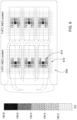
- FIG. 6 illustrates an example embodiment of a temperature distribution map generated by the ANSYS Fluent tool.
- the temperature distribution map illustrates a temperature distribution of a cooling system 600 for clusters 610 of power semiconductor chipsets 615.
- the temperature distribution map of FIG. 6 is shown in x-y plane.
- ANSYS Fluent tool can also show temperature distribution in x-y-z space.
- the computing system determines thermo-mechanical stresses endured by the components of motor system, such as switching power devices, bolted joints, DC bus capacitors, etc.
- ANSYS Fluent may be used to determine the change in junction temperature ⁇ Tj
- ANSYS Fluent takes a geometry of the object, in this example power module shown in FIG. 6 above and a power loss function (which in this example is an electrical loading function) as input parameters and data and provide temperature the distribution map as shown in FIG. 6 .
- a difference between an absolute temperature of a power semiconductor chipset 615 and the coolant temperature Tcoolant results in the change in junction temperature ⁇ Tj.
- the change in junction temperature ⁇ Tj can also be measured in a lab as part of ground truth data.
- Thermo-mechanical stresses experienced by component in power conversion system 28 are determined by learning based on data including power loss incurred in power devices, power loss incurred across inverter interconnects, vibration and a temperature gradient experienced by a stack-up temperature, coolant temperature.
- Stack-up temperature is a map and/or image of temperature variations from SiC MOSFET's die (or Si IGBT die) to coolant cannels underneath the SiC die (or Si IGBTY die). Temperatures from the die junction to the coolant vary and this variation is a function of electric power being handled by the inverter and ambient temperature around inverter. All this data is fed in a CFD tool (e.g., ANYSYS Mechanical) to determine stresses and once stress is known then stress can be expressed as function of the power function P (or the loading function), coolant temperature Tcoolant and vibration.
- CFD tool e.g., ANYSYS Mechanical
- ANSYS Mechanical may be used to determine thermo-mechanical stresses caused by separate or combined loadings of a power semiconductor and any other parts of the power conversion system 28.
- electrical loading which is a power loss function that equates to electrical loading functions. Mechanical loading is due to vibration and flow of high temperature coolant underneath parts in power conversion system 28.
- the computing system may determine a stress function at 215, which is a function of time t, the power P, the absolute junction temperature Tj and the change injunction temperature ⁇ Tj.
- the computing system may input the IoT sensor data to the stress function and calculate the stress within the motor system.
- Other considerations are also applicable and may be used to determine the stress function such as shock and vibration, humidity, etc.
- the computing system determines a reduced order physical model Mred using a reduced order computation such as (e.g., polynomial or kriging model).
- a reduced order computation such as (e.g., polynomial or kriging model).
- the exponents n, m and o may be determined based on empirical data reflecting the significance of impact of each of a, b and c, respectively.
- This equation came from lots of data collection. Once the equation is established to approximately represent stress, then any additional data received for temperature, vibration, humidity, etc., that additional data will be included in the stress function above to determine stress caused by the additional data.
- a SiC inverter uses a bus bar (e.g., conductor 16) that is insulated with a material which is prone to degradation at high ambient temperatures.
- Multi-physics based numerical simulations that capture the physics of failure mechanisms of the SiC inverter and bus bar are performed to generate the physical model.
- an electro-thermal-mechanical model (power function and temperature function determination at 205, loading function determination at 210 and stress function determination at 215) of the SiC inverter is determined.
- the electro-thermal-mechanical model uses electrical parameters from sensors as inputs and outputs of the electro-thermal-mechanical model are temperature gradients and stress values in the stack-up of the SiC inverter and the bus bar.
- the electro-thermal-mechanical model represents combined stresses experienced by electrical (power), thermal (temperature, which come from ambient and coolant) and mechanical loadings.
- the physical model may be the same as the electro-thermal-mechanical model.
- the reduced-order model can then be introduced into a digital twin platform to compute temperature and stress values under real-time operating conditions of the SiC inverter.
- IoT sensors embedded within an experimental SiC power module can stream current values to the digital twin platform and the reduced-order model will act as a virtual sensor for the junction temperature and stress values.
- the generated temperature and corresponding stress values under various operating conditions will form a dataset on which AI and ML algorithms can be applied to monitor and detect any signs of degradation in the SiC power module.
- FIG. 2B(2) illustrates a structural arrangement of the physical model generation system 201 according to an example embodiment.
- the physical model generation system 201 includes: a memory 240; a processor 220 connected to the memory 240; and various interfaces 260 connected to the processor 220.
- the various interfaces 260 may constitute an input/output interface for sending/receiving data.
- the physical model generation system 201 may include many more components than those shown in FIG. 2B(2) . However, it is not necessary that all of these generally conventional components be shown in order to disclose the illustrative example embodiment.
- the memory 240 may be a computer readable storage medium that generally includes a random-access memory (RAM), read only memory (ROM), and/or a permanent mass storage device, such as a disk drive.
- the memory 240 also stores an operating system and any other routines/modules/applications for providing the functionalities of the physical model generation system 201 (e.g., the functionalities of a physical model generation system according to the example embodiments such as those described in FIG. 2B(1) , etc.) to be executed by the processor 220.
- These software components may also be loaded from a separate computer readable storage medium into the memory 240 using a drive mechanism (not shown).
- Such separate computer readable storage medium may include a disc, tape, DVD/CD-ROM drive, memory card, or other like computer readable storage medium (not shown).
- software components may be loaded into the memory 240 via one of the various interfaces 260, rather than via a computer readable storage medium.
- Instructions may be provided to the processor 220 by the memory 240.
- the processor 220 may be configured to carry out the instructions of a computer program by performing the arithmetical, logical, and input/output operations of the system such that the processor 220 and the memory 240 cause the physical model generation system 201 to perform the functions described herein.
- the various interfaces 260 and programs stored in the memory 240 to set forth the special purpose functionalities of the physical model generation system 201 will vary depending on the implementation of the physical model generation system 201.
- the interfaces 260 may also include one or more user input devices (e.g., a keyboard, a keypad, a mouse, or the like) and user output devices (e.g., a display, a speaker, or the like).
- user input devices e.g., a keyboard, a keypad, a mouse, or the like
- user output devices e.g., a display, a speaker, or the like.
- the digital twin model generation system 202 uses the reduced order physical model of degradation Mred and ground truth and training data Gdata to train artificial intelligence and machine learning algorithms (the trained system).
- the training data may come from at least one of the three sources: (1) data measured in a lab using on an assembly of power conversion systems 28 and the motor 32 and the generator 24; (2) simulation data from ANSYS Fluent and ANSYS Mechanical, which may enrich data started for AI/ML training based on the data measured form lab; and (3) IoT sensors fitted in power conversion systems 28 and a motor 32 and a generator 24 of vehicles and used for further simulation verification by ANSYS Fluent and ANSYS Mechanical.
- the reduced order physical model of degradation Mred e.g. the electro-thermal-mechanical model, will predict stresses and stress led degradation of failure prone parts in the inverter.
- The, the physical model will have sensor data as inputs and accumulated damage as output.
- the ground truth may be produced by x-rays of parts or by dicing, slicing, and cross sectioning these failure prone parts that were subjected to HALT (highly accelerated life test) and often by manual inspection under electron microscope. Once ground truth is established, it will not be needed to repeat because damage accumulation predicted by the Physical model and ground truth data may be correlated with each other. As long as failure prone parts continue to be subjected same types of loading (power, temperature, vibration and humidity) either simultaneously or selectively, the physical model is able to assess the damage or degradation accumulation.
- the data stream from the IoT sensors such as current measurements are input into a physical model of the powertrain that will generate degradation-related output data for training the ML algorithms.
- a data stream from a single motor system may be collected to train the AI and ML algorithms, while in other example embodiments, data streams from multiple motor systems may be used to capture variations between systems (e.g., vehicle-to-vehicle variations) in degradation characteristics of the electric powertrain components.
- the AI and ML-based algorithms are trained to capture the extent of degradation of various electric powertrain components that include copper, aluminum, steel, cast iron, laminations, and plastics (by obtaining various current, voltage, temperature, etc. measurements). Additionally, continuous degradation monitoring prevents and/or reduces the likelihood of failure of components, resulting in the retention of an eco-friendly re-manufacturing of parts for an electric powertrain (e.g., a motor system).
- an electric powertrain e.g., a motor system
- FIG. 2C illustrates an example embodiment of the digital twin model generation system 202.
- the digital twin model generation system trains the artificial intelligence (AI) and machine learning (ML) algorithms. More specifically, the training at 265 includes the ground truth and training data Gdata to train artificial intelligence and machine learning algorithms and the reduced order physical model Mred.
- AI artificial intelligence
- ML machine learning
- the ground truth and training data Gdata may be compressed and used to populate data-bins. For example, a weighted average of data distributed in multidimensional space can be reduced to one data point and placed in a data bin.
- the data bins may be segmented to store data. If a weighted average of a large amount of data has a relatively lower center of gravity then it will be stored in a lower end data bin. Contrarily, if a weighted average of a large amount of data has a relatively higher center of gravity then it will be stored in a higher end of data bin.
- the data bin approach helps reduce data size including data that is stored in the cloud.
- the developed database may include data generated through (1) empirical testing (e.g., ground truth data); (2) data generated by the digital twin; and (3) real-time operation of the device (e.g., MOSFET, IGBT, inverter) on the vehicle.
- empirical testing e.g., ground truth data
- data generated by the digital twin e.g., MOSFET, IGBT, inverter
- degradation modeling is initiated at a component level, e.g., failure prone parts in the inverter such as switching devices (e.g., MOSFETs, IGBTs), capacitors and bolted joints.
- the developed degradation models for the components are then applied to assess damage accumulation to inverter on a specific vehicle when the inverter is subjected to a mission profile (e.g., loading on the inverter due to vehicle operation).
- the degradation models may then be scaled to other vehicles with similar hardware in an electric drive system of a particular vehicle type.
- the degradation models may be adjusted for other types of vehicles using inverters of different power ratings and different mission profiles (e.g., based on known power of particular device/electric drive system and coolant temperature).
- the automated degradation assessment of power devices can prolong the useful life of heavy-duty vehicles by applying controls at the user end, such as de-rating.
- the AI and ML algorithm training may be done in accordance with Baharani, et al., Real-time Deep Learning at the Edge for Scalable Reliability Modeling of Si-MOSFET Power Electronics Converters, IEEE Journal of Internet-of-Things for Smart Energy Systems, DOI 10.1109/JIOT.2019.2896174 , the entire contents of which are hereby incorporated by reference.
- Example embodiments are not limited thereto and other training algorithms may be used.
- the digital twin uses the trained system generated at 265 to predict stress in a vehicle using new data from the same or similar arrangement of sensors as described above.
- the vehicle may be a same type of vehicle that was used to generate the physical model of degradation Mred and the ground truth and training data Gdata.
- the new data may include current measurements, voltage measurements and temperature measurements.
- the new data may include other measurements such as vibration and humidity measurements.
- the digital twin uses the predicted stress to estimate a remaining life at 275. For example, temperature rise may be used by the digital twin to estimate the remaining life. For a same power level and coolant temperature, if a part of a device (e.g., an inverter) starts getting to a higher temperature, this may be indicative of degradation and used life.
- the training would include many data sets from beginning to end time temperature rise starts, those will verify amount of degradation that has occurred.
- the digital twin uses the estimated remaining life to estimate the performance degradation at 280. For example, at a given temperature rise (data from characterization or ground truth), if a reduction in applied power occurs, then this reduction in P (which is power handling capability of power conversion system 28) will be indicative of degraded performance. For example, using a MOSFET as an example at a life of 0 hours, a power P1 can be applied at the temperature Tcoolant and a change in junction temperature ⁇ Tj occurs. At a life of 12,000 hours, performance degradation maybe shown if a power P2 is applied to obtain the change in junction temperature ⁇ Tj temp at the same temperature Tcoolant with the power P2 being less than P1. Therefore, power conversion system 28, no longer can handle power P at given Tcoolant and allowed ⁇ Tj, this would be indicative of degraded performance and used up life.
- the estimated remaining life output at 275 and the estimated performance degradation output at 280 may be obtained by a cloud and/or at least one server in the cloud.
- a memory e.g., a memory 352 in a vehicle controller may store the estimated remaining life and the estimated performance degradation.
- an operator and/or maintenance scheduler (among other users of the vehicle) may have access to the estimated remaining life and the estimated performance degradation.
- the new data is shown as being input to the stress prediction at 270, it should be understood that the new data may also be used for the training at 265 to capture any new trends in real-time data.
- the twin model generation system 202 may have the components of the physical model generation system 201 that are shown in FIG. 2B(2) .
- the processor may be configured to carry out the instructions of a computer program by performing the arithmetical, logical, and input/output operations of the system such that the processor and the memory cause the twin model generation system 202 to perform the functions described herein.
- the AI and ML-based degradation modeling and damage assessment described in FIG. 2C may be built for a component of the powertrain using measured data from sensors to measure data of the component of the powertrain. The measured data then will be used to verify the accuracy of the developed physical model of the component.
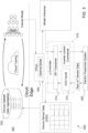
- FIG. 3 illustrates a system for degradation modeling and failure detection for an inverter according to an example embodiment.
- a vehicle 300 (e.g., a heavy-duty vehicle) includes an electric powertrain system 305 that outputs raw IoT sensor data to a microcontroller 310.
- the microcontroller 310 may be a GPU.
- the raw IoT sensor data includes input and corresponding output current measurements, input and corresponding output voltage measurements and stack-up temperature measurements related to the inverter.
- a vehicle in at least one example embodiment, includes an electric powertrain system, a plurality of sensors coupled to the electric powertrain system, the plurality of sensors configured to generate sensor data, the sensor data being measurements of at least one component of the electric powertrain system, a memory storing instructions and at least one processor configured to execute the instructions to cause the vehicle to send the generated measurements to at least one server, and obtain a digital twin associated with the at least one component.
- the at least one processor configured to executed the instructions to cause the vehicle to send additional sensor data and receive an updated digital twin based on the additional sensor data.
- the plurality of sensors are Internet of Things (IoT) sensors.
- IoT Internet of Things
- the sensor data includes temperature measurements, vibration measurements and humidity measurements associated with the at least one component.
- the at least one component is a switching device of an inverter.
- the digital twin estimates degradation of the switching device.
- the first digital twin uses a deep neural network (DNN).
- DNN deep neural network
- stack-up temperature is a map and/or image of temperature variations from SiC MOSFET's die to coolant cannels underneath the SiC die. Temperatures from the die junction to the coolant vary and this variation is a function of electric power being handled by the inverter and ambient temperature around inverter.
- Stack-up temperature may be generated using a CFD simulation followed by measurement at given Tcoolant, and P (power loading). This data may be developed by characterization and then during operation. For example, characterization means obtaining or collecting characteristics data or the characterization (e.g., at factory, laboratory, or electronics testing facility or from the transistor manufacturer) prior to commercial distribution of the characterized device/system (e.g., transistor, inverter) or prior to operation by an end user.
- characterization data or characterization may be stored in the memory 352 for retrieval and processing by a processor 404 (shown in FIG. 4 ).
- ANSYS Fluent may be used to determine an absolute temperature, a temperature rise and a temperature gradient in x-y-z plane.
- ANSYS Mechanical may be used to determine thermo-mechanical stresses caused by electrical and mechanical loading.
- Electrical loading is due to the power loss function and mechanical loading is due to vibration and hot coolant flowing at high-rate underneath components such as power devices, bolted joints etc.
- the microcontroller 310 includes an analog-to-digital converter 312 and a transceiver 314. In some example embodiments, the microcontroller 310 is the same as the control system 40, shown in FIG. 1B . In other example embodiments, the microcontroller 310 may be a dedicated controller for run AI/ML algorithms.
- the transceiver 314 sends current measurement data, voltage measurement data, temperature measurement data and change of resistance data to at least one graphics processing unit (GPU)-accelerated cloud based server 350 in a cloud.
- the GPU server may be referred to as a cloud device.
- the data is indexed by time and location (e.g., to cover variations experienced by one power conversion system to another power conversion system, from one type of vehicle to another type of vehicle and/or variations between vehicles of the same type).
- the server 350 aggregates the sensor data in a memory 352.
- the server 350 stores current measurement data, voltage measurement data, temperature measurement data and change of resistance data from a plurality of devices.
- the server treats the sensor data stored in the memory 352 as ground truth, which aids in augmenting the degradation model.
- the AI platform for real-time degradation estimation training and implementation of the SiC inverter used by the server 350 uses Deep RACE as described in Baharani, et al, Real-time Deep learning at the Edge for Scalable Reliability Modeling of Si-MOSFET Power Electronics Converters, IEEE Journal of Internet-of-Things for Smart Energy Systems (DOI 10.1109/JIOT.2019.2896174 ), the entire contents of which are herein incorporated by reference.
- most, if not all, of the sensor data is processed at the edge considering available computation power in a heavy-duty vehicle (e.g., JD 644K Hybrid Loaders), and 2) secure and continual communication link.
- a heavy-duty vehicle e.g., JD 644K Hybrid Loaders
- the vehicle 300 further includes an FPGA 320.
- the FPGA 320 hosts a trained degradation estimation model (i.e., a digital twin) sent from the server 350.
- the model received from the server 350 includes degradation models (i.e., the digital twins) of all parts in the inverter that have been modeled and represents damage accumulation occurred when the inverter is subjected to new operating conditions.
- the cloud/server model sent from the server 350 is similar to what is stored in the FPGA 320, however, the FPGA 320 provides an immediate interface with vehicle conditions. Thus, if any updates are received by the server 350, the cloud model is updated and the cloud model will have more history and will be data rich for further training.
- the model stored in the FPGA 320 may be a reduced order model and a selected trained model (e.g., selected according to desired performance metrics such as accuracy of prediction of stress).
- the server/cloud 350 may send the selected trained model to other vehicles of the same type as the vehicle 300 and/or that have a same type of electric powertrain system as the vehicle 300.
- the selected trained model may be sent to all combines that communicate with the server/cloud 350.
- the server/cloud 350 includes a memory storing instructions; and at least one processor configured to executed the instructions to cause the computer system to obtain sensor data, the sensor data corresponding to measurements of at least one component of an electric powertrain system of at least one vehicle, and generate a first digital twin based on the obtained sensor data, the first generated twin associated with a type of the at least one vehicle.
- the at least one processor configured to executed the instructions to cause the computer system to send the first digital twin to the at least one vehicle.
- the at least one processor configured to executed the instructions to cause the computer system to send the first digital twin to other vehicles of the same type of the at least one vehicle.
- the at least one processor configured to executed the instructions to cause the computer system to obtain additional sensor data, update the first digital twin based on the additional sensor data; and send the updated digital twin to the at least one vehicle.
- the at least one processor configured to executed the instructions to cause the computer system to generate a second digital twin based on the additional sensor data, the second digital twin associated with a second type of vehicle, the second type being different than the type of the at least one vehicle.
- the sensor data is data generated from one or more Internet of Things (IoT) sensors coupled to the vehicle.
- IoT Internet of Things
- the sensor data includes temperature measurements, vibration measurements and humidity measurements associated with at least one component of an electric powertrain system of the vehicle.
- the at least one component is a switching device of an inverter.
- the first digital twin estimates degradation of the switching device.
- the first digital twin uses a deep neural network (DNN).
- DNN deep neural network
- the cloud model may be continuously upgraded by the at least one server 350 as more and more data is measured during real-time operation of the vehicle and the cloud may continuously keep refining the model including capturing variability among many vehicles that use same drivetrain and many type of drivetrain in deployed in many vehicles.
- the GPU-accelerated server 350 provides an ecosystem for a database, responsible for device-specific data aggregation, and a DNN framework, that provides a library to facilitate DNN model training.
- the FPGA 320 hosts a customized hardware solution for real-time model inferencing at the edge. Integrating these two components together provides a closed-loop real-world simulation of the entire life cycle of the inverter.
- Pre-existing datasets may be used to provide the FPGA 320 and the server 350 with inverter (or SiC power module) specific data for model inferencing, and data aggregation and training, respectively.
- inverter or SiC power module
- the communication between both the FPGA 320 and the server 350, as well as intra-communication within the server (database and training), provides functional verification of the closed-loop simulation.
- the real-world simulation, processing of SiC power module data at the edge for real-time inference, and data aggregation and training in the cloud provides an AI platform, which will be capable of a prediction of the quality and quantity of material that can be reclaimed from the powertrain which is ready for remanufacturing.
- the DNN model is trained using data measured by IoT sensors instrumented in the SiC inverter components.
- the measured data may be preprocessed and the AI-based algorithm may be altered in order to provide reliable feedback to monitor and control the health and efficiency of vitals parts in the inverter.
- the server 350 will replace the existing model and dataset within the AI-ready platform.
- the existing model may be replaced initially when the accuracy is greater than 50% and then eventually replaced when the accuracy is at a higher level such as 75% or 90%.
- the time prediction window may be adjusted and is not limited to 90 seconds.
- Deep RACE moves beyond mainstream device modeling and traditional reliability analysis by combining advanced sensing solutions with cutting-edge deep learning and edge computing techniques, as shown in FIG. 3 . While Deep RACE has been discussed with respect to the reliability modeling of parts used in a SiC inverter, the proposed algorithmic construct and system- level solution for real-time degradation assessment can be extended to other components of an electric powertrain (e.g., components shown in FIG. 1A ).
- a hybrid condition-based prediction model technique will be used in the assessment of quality and quantity of reclaimable material for remanufacturing of an electric powertrain. At least some example embodiments assess the behavior of individual components in the powertrain, based on both usage history as inferred from IoT sensors' data and expected future load profiles.
- a data-driven DNN model is utilized at the edge for real-time component-specific reliability prediction and modeling, while the cloud infrastructure performs high-level metadata aggregation and analysis across many components from multiple vehicles. Therefore, the models for each component will be updated based on current device operating conditions to keep track of quality and quantity of the reclaimable material for remanufacturing.
- the Deep Learning (DL) algorithm of Deep RACE is based on an extension of Temporal Convolutional Networks (TCN).
- FIG. 4 illustrates a server according to at least one example embodiment.
- the server 350 includes: a memory 352; a processor 404 (e.g., a GPU) connected to the memory 352; and various interfaces 402 connected to the processor 404.
- the various interfaces 402 may constitute a transceiver for transmitting/receiving data from/to the vehicle 300.
- the server 350 may include many more components than those shown in FIG. 4 . However, it is not necessary that all of these generally conventional components be shown in order to disclose the illustrative example embodiment.
- the memory 352 may be a computer readable storage medium that generally includes a random access memory (RAM), read only memory (ROM), and/or a permanent mass storage device, such as a disk drive.
- the memory 352 also stores an operating system and any other routines/modules/applications for providing the functionalities of the cloud/server 350 (e.g., functionalities according to the example embodiments, etc.) to be executed by the processor 404.
- These software components may also be loaded from a separate computer readable storage medium into the memory 352 using a drive mechanism (not shown).
- Such separate computer readable storage medium may include a disc, tape, DVD/CD-ROM drive, memory card, or other like computer readable storage medium (not shown).
- software components may be loaded into the memory 352 via one of the various interfaces 402, rather than via a computer readable storage medium.
- the processor 404 may be configured to carry out the instructions of a computer program by performing the arithmetical, logical, and input/output operations of the system such that the processor 404 and the memory 352 cause the server 350 to perform the functions described herein.
- the processor 404 and the memory 352 including computer program code, the at least one memory and the computer program code configured to, with the at least one processor, cause the server to obtain sensor data, the sensor data corresponding to measurements of at least one component of an electric powertrain system of at least one vehicle; and generate a first digital twin based on the obtained sensor data, the first generated twin associated with a type of the at least one vehicle.
- the various interfaces 402 may include components that interface the processor 404 with other input/output components. As will be understood, the various interfaces 402 and programs stored in the memory 352 to set forth the special purpose functionalities of the server 350 will vary depending on the implementation of the server 350.
- the interfaces 402 may also include one or more user input devices (e.g., a keyboard, a keypad, a mouse, or the like) and user output devices (e.g., a display, a speaker, or the like).
- user input devices e.g., a keyboard, a keypad, a mouse, or the like
- user output devices e.g., a display, a speaker, or the like.
- the configuration shown in FIG. 4 may be utilized to implement, inter alia, the vehicle 300 and/or devices.
- the memory 352 may store an operating system and any other routines/modules/applications for providing the functionalities of the vehicle, etc. (e.g., functionalities of these elements, methods according to the example embodiments, determination of degradation, etc.) to be executed by the processor 404.
- the digital twins take into account uncertainties caused by changes the number of IoT sensors in the component of the powertrain.
- at least some example embodiments capture behaviors of key components of an electric powertrain under different mission profiles, resulting in the developed technique operating only on electrical sensors that are deployed for motor control applications and could feed data (voltage and current) to physical models of key components in the electric powertrain.
- Such flexibility of introduced AI and ML-based degradation assessment technique will make it independent of vehicle form, applications and function, as shown in FIG. 5 .
- each vehicle includes a telematics gateway (TG) which serves as a data communication link from the vehicle to the cloud.
- TG telematics gateway
- a vehicle in at least one example embodiment, includes an electric powertrain system, a plurality of sensors coupled to the electric powertrain system, the plurality of sensors configured to generate sensor data, the sensor data being measurements of at least one component of the electric powertrain system; a memory storing instructions; and at least one processor configured to execute the instructions to cause the vehicle to, send the generated measurements to at least one other vehicle, and obtain a digital twin associated with the at least one component.
- a plurality of vehicles 510, 515 and 520 may form a network 500.
- the server 350 may communicate with at least one of the vehicles 510, 515 and 520 through a respective edge layer.
- the vehicle 510 may send the selected train model to the vehicles 515 and 520.
- the vehicle 510 may send the selected trained model to the vehicles 515 and 520 through the network 500. Additionally, the vehicle 510 may teach the vehicle 515 and 520. For example, using AI/ML backed GANN (genetic adversarial neural network) deployed in two vehicles could compete with each other and train each other depending upon condition they endure. Once more and more data and used cases becomes available, there is possibility that is less experienced AI/ML technique deployed on a new vehicle will learn from an experienced vehicle or set of vehicles that have endured far more field hours.
- GANN genetic adversarial neural network
- the vehicle 510 is a different type of vehicle than the vehicles 515 and 520, which are the same type.
- the vehicle 510 may send trained models to the vehicles 515 and 520 for components that are the same across the vehicles, 510, 515 and 520 (e.g., MOSFETs).
Landscapes
- Physics & Mathematics (AREA)
- General Physics & Mathematics (AREA)
- Engineering & Computer Science (AREA)
- Theoretical Computer Science (AREA)
- Evolutionary Computation (AREA)
- Artificial Intelligence (AREA)
- General Engineering & Computer Science (AREA)
- Software Systems (AREA)
- Life Sciences & Earth Sciences (AREA)
- Mathematical Physics (AREA)
- Biomedical Technology (AREA)
- General Health & Medical Sciences (AREA)
- Molecular Biology (AREA)
- Computing Systems (AREA)
- Computational Linguistics (AREA)
- Data Mining & Analysis (AREA)
- Biophysics (AREA)
- Health & Medical Sciences (AREA)
- Computer Vision & Pattern Recognition (AREA)
- Medical Informatics (AREA)
- Computer Hardware Design (AREA)
- Geometry (AREA)
- Inverter Devices (AREA)
Applications Claiming Priority (1)
| Application Number | Priority Date | Filing Date | Title |
|---|---|---|---|
| US202163230903P | 2021-08-09 | 2021-08-09 |
Publications (1)
| Publication Number | Publication Date |
|---|---|
| EP4137983A1 true EP4137983A1 (de) | 2023-02-22 |
Family
ID=82258150
Family Applications (1)
| Application Number | Title | Priority Date | Filing Date |
|---|---|---|---|
| EP22175284.3A Pending EP4137983A1 (de) | 2021-08-09 | 2022-05-25 | Systeme und verfahren zum beurteilen von verschlechterung in antriebskomponenten |
Country Status (2)
| Country | Link |
|---|---|
| US (1) | US20230042433A1 (de) |
| EP (1) | EP4137983A1 (de) |
Cited By (1)
| Publication number | Priority date | Publication date | Assignee | Title |
|---|---|---|---|---|
| US20240403836A1 (en) * | 2021-12-28 | 2024-12-05 | Hitachi, Ltd. | Product circulation method and processor system |
Families Citing this family (5)
| Publication number | Priority date | Publication date | Assignee | Title |
|---|---|---|---|---|
| US20210327165A1 (en) * | 2018-11-27 | 2021-10-21 | Sumitomo Electric Industries, Ltd. | Vehicle malfunction prediction system, monitoring device, vehicle malfunction prediction method, and vehicle malfunction prediction program |
| US12340634B2 (en) * | 2022-04-21 | 2025-06-24 | Ford Global Technologies, Llc | Systems and methods using dual vehicle digital twins for model-based learning and remotely-operated vehicles |
| US20240241505A1 (en) * | 2023-01-18 | 2024-07-18 | Hitachi, Ltd. | System and method for applying a priori inspection to prioritize cores for re* operations |
| GB2634211A (en) * | 2023-09-27 | 2025-04-09 | Mercedes Benz Group Ag | A motor driver with a temperature sensor for a vehicle, a method for operating a vehicle, and corresponding vehicle |
| CN118199451B (zh) * | 2024-02-04 | 2025-10-10 | 西南交通大学 | 一种基于事件驱动的电机驱动系统数字孪生在线实现方法 |
Citations (4)
| Publication number | Priority date | Publication date | Assignee | Title |
|---|---|---|---|---|
| US8744794B2 (en) | 2011-02-28 | 2014-06-03 | Deere & Company | Method and apparatus for characterizing an interior permanent magnet machine |
| US20180257683A1 (en) * | 2017-03-09 | 2018-09-13 | General Electric Company | System for vehicle subsystem control |
| US10191021B2 (en) | 2015-02-27 | 2019-01-29 | Deere & Company | Method for estimating a temperature of a transistor |
| CN113125954A (zh) * | 2021-04-16 | 2021-07-16 | 安徽大学 | 一种电动汽车驱动电机的故障诊断方法和应用 |
Family Cites Families (3)
| Publication number | Priority date | Publication date | Assignee | Title |
|---|---|---|---|---|
| US20170286572A1 (en) * | 2016-03-31 | 2017-10-05 | General Electric Company | Digital twin of twinned physical system |
| US20210157312A1 (en) * | 2016-05-09 | 2021-05-27 | Strong Force Iot Portfolio 2016, Llc | Intelligent vibration digital twin systems and methods for industrial environments |
| US20210357555A1 (en) * | 2018-09-14 | 2021-11-18 | Northwestern University | Data-driven representation and clustering discretization method and system for design optimization and/or performance prediction of material systems and applications of same |
-
2022
- 2022-04-29 US US17/733,043 patent/US20230042433A1/en active Pending
- 2022-05-25 EP EP22175284.3A patent/EP4137983A1/de active Pending
Patent Citations (4)
| Publication number | Priority date | Publication date | Assignee | Title |
|---|---|---|---|---|
| US8744794B2 (en) | 2011-02-28 | 2014-06-03 | Deere & Company | Method and apparatus for characterizing an interior permanent magnet machine |
| US10191021B2 (en) | 2015-02-27 | 2019-01-29 | Deere & Company | Method for estimating a temperature of a transistor |
| US20180257683A1 (en) * | 2017-03-09 | 2018-09-13 | General Electric Company | System for vehicle subsystem control |
| CN113125954A (zh) * | 2021-04-16 | 2021-07-16 | 安徽大学 | 一种电动汽车驱动电机的故障诊断方法和应用 |
Non-Patent Citations (5)
| Title |
|---|
| BAHARANI ET AL.: "Real-time Deep learning at the Edge for Scalable Reliability Modeling of Si-MOSFET Power Electronics Converters", IEEE JOURNAL OF INTERNET-OF-THINGS FOR SMART ENERGY SYSTEMS (DOI 10.1109/JIOT.2019.2896174 |
| BAHARANI ET AL.: "Real-time Deep Learning at the Edge for Scalable Reliability Modeling of Si-MOSFET Power Electronics Converters", IEEE JOURNAL OF INTERNET-OF-THINGS FOR SMART ENERGY SYSTEMS, DOI 10.1109/JIOT.2019.2896174 |
| MOHAMMADREZA BAHARANI ET AL: "Real-time Deep Learning at the Edge for Scalable Reliability Modeling of Si-MOSFET Power Electronics Converters", ARXIV.ORG, CORNELL UNIVERSITY LIBRARY, 201 OLIN LIBRARY CORNELL UNIVERSITY ITHACA, NY 14853, 4 August 2019 (2019-08-04), XP081455407, DOI: 10.1109/JIOT.2019.2896174 * |
| SAMATAS G G ET AL: "Predictive Maintenance -- Bridging Artificial Intelligence and IoT", ARXIV.ORG, CORNELL UNIVERSITY LIBRARY, 201 OLIN LIBRARY CORNELL UNIVERSITY ITHACA, NY 14853, 20 March 2021 (2021-03-20), XP081930480 * |
| VENKATESAN SUCHITRA ET AL: "Health monitoring and prognosis of electric vehicle motor using intelligent-digital twin", IET ELECTRIC POWER APPLICATIONS, IET, UK, vol. 13, no. 9, 1 September 2019 (2019-09-01), pages 1328 - 1335, XP006081548, ISSN: 1751-8660, DOI: 10.1049/IET-EPA.2018.5732 * |
Cited By (1)
| Publication number | Priority date | Publication date | Assignee | Title |
|---|---|---|---|---|
| US20240403836A1 (en) * | 2021-12-28 | 2024-12-05 | Hitachi, Ltd. | Product circulation method and processor system |
Also Published As
| Publication number | Publication date |
|---|---|
| US20230042433A1 (en) | 2023-02-09 |
Similar Documents
| Publication | Publication Date | Title |
|---|---|---|
| EP4137983A1 (de) | Systeme und verfahren zum beurteilen von verschlechterung in antriebskomponenten | |
| US11491892B2 (en) | Selection apparatus, selection method, and storage medium | |
| CN111751751B (zh) | 寿命预测装置、寿命预测方法及存储介质 | |
| CN102798535A (zh) | 用于估计设备的剩余寿命的系统和方法 | |
| Mahmoud et al. | Robust multiple-fault diagnosis of PMSM drives under variant operations and noisy conditions | |
| Van Der Broeck et al. | Intelligent monitoring and maintenance technology for next-generation power electronic systems | |
| Niu et al. | Demagnetization monitoring and life extending control for permanent magnet-driven traction systems | |
| Reiter et al. | Design of thermal management systems for battery electric vehicles | |
| Niu et al. | Prognostic control-enhanced maintenance optimization for multi-component systems | |
| Zsuga et al. | Data-driven onboard inter-turn short circuit fault diagnosis for electric vehicles by using real-time simulation environment | |
| CN114552691A (zh) | 充电控制系统、充电控制装置以及存储介质 | |
| Bhoi et al. | A data-driven thermal digital twin of a 3-phase inverter using hi-fidelity multi-physics modelling | |
| Pliuhin et al. | A digital twin design of induction motor with squirrel-cage rotor for insulation condition prediction | |
| Kamboj et al. | An intelligent fault detection (IFD) system for lithium-ion battery using machine learning approach | |
| Hafner et al. | Automated virtual prototyping of permanent magnet synchronous machines for HEVs | |
| Bhoi et al. | A Streamlined Test-Oriented Lifetime Assessment Framework for Automotive Power Electronics Converters | |
| Kumar et al. | Advancements in fault detection and diagnosis methods for electric vehicles: a review | |
| Vishnu Murthy et al. | Overview of battery management systems in electric vehicles | |
| James | Health monitoring of IGBTs in automotive power converter systems | |
| Alghassi et al. | Reliability enhance powertrain using fuzzy knowledge base prognostics model | |
| Hu et al. | Digital Twin of Power Modules based on Physics Informed Machine Learning | |
| Chakraborty et al. | Reliability as a Service Revolutionizes EV and Charging System Reliability | |
| Dini et al. | Model-Based Design and AI for Monitoring Systems in Automotive Power Electronics | |
| uz Zaman | Predictive Maintenance of Electric Vehicle Components Using IoT Sensors | |
| Sakhare et al. | Physics of failure-based life cycle assessment for SRM power converter components: a sustainable approach to realistic and safe electronic product development |
Legal Events
| Date | Code | Title | Description |
|---|---|---|---|
| PUAI | Public reference made under article 153(3) epc to a published international application that has entered the european phase |
Free format text: ORIGINAL CODE: 0009012 |
|
| STAA | Information on the status of an ep patent application or granted ep patent |
Free format text: STATUS: THE APPLICATION HAS BEEN PUBLISHED |
|
| AK | Designated contracting states |
Kind code of ref document: A1 Designated state(s): AL AT BE BG CH CY CZ DE DK EE ES FI FR GB GR HR HU IE IS IT LI LT LU LV MC MK MT NL NO PL PT RO RS SE SI SK SM TR |
|
| STAA | Information on the status of an ep patent application or granted ep patent |
Free format text: STATUS: REQUEST FOR EXAMINATION WAS MADE |
|
| 17P | Request for examination filed |
Effective date: 20230822 |
|
| RBV | Designated contracting states (corrected) |
Designated state(s): AL AT BE BG CH CY CZ DE DK EE ES FI FR GB GR HR HU IE IS IT LI LT LU LV MC MK MT NL NO PL PT RO RS SE SI SK SM TR |
|
| STAA | Information on the status of an ep patent application or granted ep patent |
Free format text: STATUS: EXAMINATION IS IN PROGRESS |
|
| 17Q | First examination report despatched |
Effective date: 20250820 |
|
| RAP3 | Party data changed (applicant data changed or rights of an application transferred) |
Owner name: DEERE & COMPANY |