EP4137853B1 - Connector shroud - Google Patents
Connector shroud Download PDFInfo
- Publication number
- EP4137853B1 EP4137853B1 EP22182470.9A EP22182470A EP4137853B1 EP 4137853 B1 EP4137853 B1 EP 4137853B1 EP 22182470 A EP22182470 A EP 22182470A EP 4137853 B1 EP4137853 B1 EP 4137853B1
- Authority
- EP
- European Patent Office
- Prior art keywords
- cam
- inner housing
- coupling nut
- connector shroud
- column
- Prior art date
- Legal status (The legal status is an assumption and is not a legal conclusion. Google has not performed a legal analysis and makes no representation as to the accuracy of the status listed.)
- Active
Links
Images




Classifications
-
- G—PHYSICS
- G02—OPTICS
- G02B—OPTICAL ELEMENTS, SYSTEMS OR APPARATUS
- G02B6/00—Light guides; Structural details of arrangements comprising light guides and other optical elements, e.g. couplings
- G02B6/24—Coupling light guides
- G02B6/36—Mechanical coupling means
- G02B6/38—Mechanical coupling means having fibre to fibre mating means
- G02B6/3807—Dismountable connectors, i.e. comprising plugs
- G02B6/389—Dismountable connectors, i.e. comprising plugs characterised by the method of fastening connecting plugs and sockets, e.g. screw- or nut-lock, snap-in, bayonet type
- G02B6/3891—Bayonet type
-
- H—ELECTRICITY
- H01—ELECTRIC ELEMENTS
- H01R—ELECTRICALLY-CONDUCTIVE CONNECTIONS; STRUCTURAL ASSOCIATIONS OF A PLURALITY OF MUTUALLY-INSULATED ELECTRICAL CONNECTING ELEMENTS; COUPLING DEVICES; CURRENT COLLECTORS
- H01R13/00—Details of coupling devices of the kinds covered by groups H01R12/70 or H01R24/00 - H01R33/00
- H01R13/62—Means for facilitating engagement or disengagement of coupling parts or for holding them in engagement
- H01R13/622—Screw-ring or screw-casing
-
- H—ELECTRICITY
- H01—ELECTRIC ELEMENTS
- H01R—ELECTRICALLY-CONDUCTIVE CONNECTIONS; STRUCTURAL ASSOCIATIONS OF A PLURALITY OF MUTUALLY-INSULATED ELECTRICAL CONNECTING ELEMENTS; COUPLING DEVICES; CURRENT COLLECTORS
- H01R13/00—Details of coupling devices of the kinds covered by groups H01R12/70 or H01R24/00 - H01R33/00
- H01R13/62—Means for facilitating engagement or disengagement of coupling parts or for holding them in engagement
- H01R13/629—Additional means for facilitating engagement or disengagement of coupling parts, e.g. aligning or guiding means, levers, gas pressure electrical locking indicators, manufacturing tolerances
- H01R13/62905—Additional means for facilitating engagement or disengagement of coupling parts, e.g. aligning or guiding means, levers, gas pressure electrical locking indicators, manufacturing tolerances comprising a camming member
Definitions
- This invention generally relates to a connector shroud, more particularly, to an optical fiber connector weather shroud.
- An optical fiber is generally a glass fiber configured to carry light. Individual fibers may be grouped into a line capable of carrying large amounts of data simultaneously.
- each individual fiber When constructing a fiber optic network, each individual fiber is generally connected to both a source and a destination device. Additionally, along the fiber optic run between the source and the destination, various connections or couplings may be made on the optical fiber to adjust the length of the fiber. Each connection or coupling requires a connector and adapter to align the fibers such that the light can transmit without interruption.
- a connector system for optical fibers and electrical conductors is disclosed in US Pat. No. 9,755,382 .
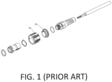
- the main feature of the design is that after the coupling nut 18 has been twisted into a closed position, it can be locked in place by the lock ring 26.
- the above-mentioned locking method is to twist the coupling nut 18 clockwise and then push the lock ring 26 forward to press against the coupling nut 18 to prevent the coupling nut 18 from rotating.
- the lock ring 26 is pulled backward and the coupling nut 18 is twisted counterclockwise. It should be noted that if the operator forgets to push up the lock ring 26 after locking the coupling nut 18, the coupling nut 18 cannot be ensured to remain in the closed position.
- the above design has the disadvantage of that the locking and unlocking motions require sufficient clearance for the operator to grip and twist the connector. Since it is necessary to leave space for the operator's hands to manipulate the connector, it is not possible for connectors to be installed side-by-side close to one another. This limits the density of connectors that can be installed in a panel and requires larger spacing between connectors on the panel.
- US 2020/264383 A1 discloses a connector shroud comprising a cylindrical inner housing having an alignment key formed on an outer surface, the alignment key extending in a longitudinal direction; a coupling nut sleeved onto the inner housing; and a collar sleeved onto the inner housing.
- the collar comprises an alignment recess on its inner surface that receives the alignment key, to inhibit the collar from rotating on the inner housing.
- the collar comprises several guiding grooves having a triangular shape, and the coupling nut comprises pins that slide in the guiding grooves, such that the coupling nut can be moved between a locked and an unlocked state.
- the present invention provides a connector shroud that the locking and unlocking of the connector shroud can be implemented by an operator with only one hand.
- the connector shroud of the present invention includes an inner housing, a cam, a coupling nut and a lock nut.
- the inner housing has a grooved control link formed on an outer surface. The grooved control link extends in a longitudinal direction.
- the cam is disposed on the inner housing and is rotatable on the inner housing.
- the coupling nut is sleeved onto the inner housing.
- the coupling nut is configured to be coupled to an object.
- the coupling nut includes a tab extending from a rear end.
- the tab has a control slot formed thereon.
- the control slot extends in a direction not parallel to the longitudinal direction.
- the lock nut is sleeved onto the inner housing and includes a first pin and a second pin formed on an inner surface.
- the first pin is movable in the grooved control link and the second pin is movable in the control slot.
- a movement of the lock nut causes the coupling nut to rotate.
- the lock nut contacts the cam to make the cam rotate.
- the rotating cam applies a force perpendicular to the longitudinal direction to the tab to rotate the coupling nut.
- a user may move the lock nut longitudinally to rotate the coupling nut without need of directly twisting the coupling nut. In this way there is no need to vacate the space beside the coupling nut for the user to twist the coupling nut. Therefore, the installation density of the connectors can be improved.
- the connector shroud includes a cable gland 100, an inner housing 200, a coupling nut 300, a lock nut 400 and a cam 500.
- the cable gland 100, the inner housing 200, the coupling nut 300, the lock nut 400 and the cam 500 may be constructed of plastics by an injection molding process.
- the cable gland 100 may be made from a flexible material and provide strain relief on cable (not shown) using materials and attachment techniques as are known in the art.
- the cable gland 100 has a hollow body whose lengthwise direction is parallel to a longitudinal direction 911.
- the cable gland 100 has a thread formed on inner surfaces of the front end for being coupled to the inner housing 200.
- the inner housing 200 is hollow and has a cylindrical body whose lengthwise direction is parallel to the longitudinal direction 911.
- An annular groove is formed at the front section of the outer surface of the inner housing 200 for receiving a sealing ring (not shown).
- An annular protrusion 220 located behind the annular groove is formed on the outer surface of the inner housing 200, the annular surface of which is perpendicular to the longitudinal direction 911.
- Three notches 222 are formed in the protrusion 220 and are arranged at equal intervals.
- Two identical grooved control links 230 are arranged on the outer surface of the inner housing 200 on two opposite sides and extend in the longitudinal direction 911.
- Two bumps 231, 232 are formed on the bottom of each of the grooved control links 230, wherein the bump 231 is located closer to the protrusion 220 than the bump 232.
- a cam groove 240 is formed on the outer surface of the inner housing 200.
- the cam groove 240 is a rectangular groove and a column 242 is formed at the bottom of the cam groove 240.
- the coupling nut 300 is hollow and has a cylindrical body for being sleeved onto the inner housing 200.
- a plurality of pins 320 arranged at equal intervals is formed on the inner surface of the front end of the coupling nut 300.
- Two mutually opposite tabs 310 with an arc-shaped cross-section protrude from the rear end of the coupling nut 300.
- Each of the tabs 310 has two opposite side surfaces 311 and 312, respectively facing the side surfaces 312 and 311 of the other tab 310 across a gap 316.
- Two identical and mutually opposite control slots 330 are respectively formed on the tabs 310.
- the control slot 330 extends from the rear end of the tab 310 toward the front end of the coupling nut 300 in a direction not parallel and not perpendicular to the longitudinal direction 911.
- an inclined surface 340 is formed on one of the tabs 310 and is adjacent to the side surface 311 and the control slot 330 on the tab 310.
- the lock nut 400 is hollow and has a cylindrical body for being sleeved onto the inner housing 200 and covering the tabs 310 of the coupling nut 300.
- Two mutually opposite second pins 420 are formed at the front section of the inner surface of the lock nut 400.
- Two mutually opposite first pins 410 are formed on the inner surface of the lock nut 400.
- two mutually opposite openings 430 are formed on the lateral surface of the lock nut 400 and two cantilevers 440 are provided respectively in the openings 430.
- the cantilevers 440 extend from the lateral surface of the lock nut 400 and have a lengthwise direction parallel to the longitudinal direction 911.
- the two first pins 410 are respectively coupled to the front sections of the two cantilevers 440.
- an elongated extension 450 extending in the longitudinal direction 911 is formed on the inner surface of the lock nut 400.
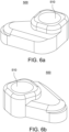
- the cam 500 has a substantially triangular shape and a circular opening 510 is formed thereon for accommodating the column 242 on the inner housing 200.
- the center of gravity of the cam 500 is designed not to fall within the opening 510.
- the cam 500 is used to be placed in the cam groove 240 on the inner housing 200 and allows the column 242 to be received in the opening 510.
- FIGS. 7a , 7b and 7c are three elevated perspective views illustrating the connector shroud of the present invention.
- the rear end of the inner housing 200 is coupled to the front end of the cable gland 100.
- the cam 500 is disposed in the cam groove 240 on the inner housing 200 and the column 242 is inserted into the opening 510.
- the cam 500 is pivotally connected to the column 242 and the column 242 serves as a rotation axis so that the cam 500 is able to rotate about the column 242.
- the coupling nut 300 is sleeved onto the front section of the inner housing 200.
- the lock nut 400 is sleeved onto the middle section of the inner casing 200 and covers the cam 500 and the tabs 310 of the coupling nut 300.
- the two first pins 410 on the inner surface of the lock nut 400 are respectively located in the two grooved control links 230 on the inner housing 200.
- the two second pins 420 on the inner surface of the lock nut 400 are respectively arranged in the two control slots 330 on the coupling nut 300.
- the connectors to be shielded are arranged in the inner housing 200 (not shown).
- FIG. 8 shows a conventional adapter 800, which is provided on an apparatus so that the connectors provided in the apparatus may be coupled to other connectors.
- the adapter 800 includes a hollow cylinder 820 having a thread 810 formed thereon so that the adapter 800 may be secured to the apparatus with a nut.
- the adapter 800 is further provided with a plurality of grooves 840 formed on the cylinder 820, each of which includes a guiding groove portion 841 and a retaining groove portion 842.
- the guiding groove portion 841 extends both axially and circumferentially, e.g., generally spirally, about at least a portion of the wall of the cylinder 820, e.g., along and about the longitudinal direction 911, respectively.
- the connector shroud of the present invention may be mated with an object, such as the adapter 800 of FIG. 8 , so that the connectors provided in the connector shroud may be coupled with the connectors provided in the adapter 800 (not shown).
- the front end of the inner housing 200 of the connector shroud is inserted into the cylinder 820 of the adapter 800 such that the pins 320 on the inner surface of the coupling nut 300 respectively enter the guiding groove portions 841 from the entrances 841e.
- the coupling nut 300 is twisted to allow the pins 320 to slide from the guiding groove portions 841 into the retaining groove portions 842 respectively.
- the coupling nut 300 is now coupled to the adapter 800 and the connector shroud is mated with the adapter 800. During the rotation of the coupling nut 300, the inner housing 200 is restricted and therefore cannot be rotated. If it is desired to detach the connector shroud from the adapter 800, the coupling nut 300 is twisted in the opposite direction to allow the pins 320 to slide out of the grooves 840 from the entrances 841e. In other embodiments, the coupling nut 300 is not limited to be coupled to the adapter 800, and may be designed to be coupled to other objects.
- the two first pins 410 of the lock nut 400 may respectively move forward or backward in the grooved control links 230 on the inner housing 200.
- the lock nut 400 When a user moves the lock nut 400 to cause the first pins 410 to pass over the bumps 231 respectively, the user will feel a change in resistance. This change in resistance provides the user with tactile feedback.
- the two second pins 420 of the lock nut 400 may move respectively in the two control slots 330 of the coupling nut 300.
- the coupling nut 300 will rotate clockwise to be locked on the adapter 800. If it is desired to unlock the coupling nut 300, pulling the lock nut 400 backward causes the coupling nut 300 to rotate counterclockwise to be unlocked from the adapter 800.
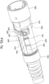
- the cam 500 is located in the gap 316 between the tabs 310.
- the lock nut 400 When the lock nut 400 is pushed toward the adapter 800, its extension 450 will be in contact with the cam 500 as shown in FIG. 9 .
- the cam 500 is pushed to rotate around the column 242 on the inner housing 200 as shown in FIG. 10 .
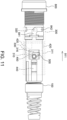
- the cam 500 continues to rotate and press against the inclined surface 340 on the tab 310, thus a force perpendicular to the longitudinal direction 911 is applied to the coupling nut 300. This force causes the coupling nut 300 to rotate clockwise to help it lock on the adapter 800 as shown in FIG. 11 .
- moving the lock nut 400 forward causes the cam 500 to rotate the coupling nut 300 so that the coupling nut 300 may be locked more easily.
- the cam 500 is designed such that its center of gravity does not fall within the column 242 and the tilting of the connector shroud allows the cam 500 to rotate back to its initial position.
- a user may move the lock nut 400 longitudinally to rotate the coupling nut 300 without need of directly twisting the coupling nut 300. In this way there is no need to vacate the space beside the coupling nut 300 for the user to twist the coupling nut 300. Therefore, the installation density of the connectors can be improved.
Landscapes
- Physics & Mathematics (AREA)
- General Physics & Mathematics (AREA)
- Optics & Photonics (AREA)
- Details Of Connecting Devices For Male And Female Coupling (AREA)
- Seal Device For Vehicle (AREA)
- Coupling Device And Connection With Printed Circuit (AREA)
- Paper (AREA)
Description
- This invention generally relates to a connector shroud, more particularly, to an optical fiber connector weather shroud.
- Recently, the use of fiber optics for communications purposes has grown immensely. Data, voice, and other communication networks are increasingly using fiber optics to carry information. An optical fiber is generally a glass fiber configured to carry light. Individual fibers may be grouped into a line capable of carrying large amounts of data simultaneously.
- When constructing a fiber optic network, each individual fiber is generally connected to both a source and a destination device. Additionally, along the fiber optic run between the source and the destination, various connections or couplings may be made on the optical fiber to adjust the length of the fiber. Each connection or coupling requires a connector and adapter to align the fibers such that the light can transmit without interruption.
- Referring to
FIG. 1 , a connector system for optical fibers and electrical conductors is disclosed inUS Pat. No. 9,755,382 coupling nut 18 has been twisted into a closed position, it can be locked in place by thelock ring 26. The above-mentioned locking method is to twist thecoupling nut 18 clockwise and then push thelock ring 26 forward to press against thecoupling nut 18 to prevent thecoupling nut 18 from rotating. To unlock, thelock ring 26 is pulled backward and thecoupling nut 18 is twisted counterclockwise. It should be noted that if the operator forgets to push up thelock ring 26 after locking thecoupling nut 18, thecoupling nut 18 cannot be ensured to remain in the closed position. - Further, the above design has the disadvantage of that the locking and unlocking motions require sufficient clearance for the operator to grip and twist the connector. Since it is necessary to leave space for the operator's hands to manipulate the connector, it is not possible for connectors to be installed side-by-side close to one another. This limits the density of connectors that can be installed in a panel and requires larger spacing between connectors on the panel.
-
US 2020/264383 A1 discloses a connector shroud comprising a cylindrical inner housing having an alignment key formed on an outer surface, the alignment key extending in a longitudinal direction; a coupling nut sleeved onto the inner housing; and a collar sleeved onto the inner housing. The collar comprises an alignment recess on its inner surface that receives the alignment key, to inhibit the collar from rotating on the inner housing. In addition, the collar comprises several guiding grooves having a triangular shape, and the coupling nut comprises pins that slide in the guiding grooves, such that the coupling nut can be moved between a locked and an unlocked state. - In view of the above, the present invention provides a connector shroud that the locking and unlocking of the connector shroud can be implemented by an operator with only one hand.
- The connector shroud of the present invention includes an inner housing, a cam, a coupling nut and a lock nut. The inner housing has a grooved control link formed on an outer surface. The grooved control link extends in a longitudinal direction. The cam is disposed on the inner housing and is rotatable on the inner housing. The coupling nut is sleeved onto the inner housing. The coupling nut is configured to be coupled to an object. The coupling nut includes a tab extending from a rear end. The tab has a control slot formed thereon. The control slot extends in a direction not parallel to the longitudinal direction. The lock nut is sleeved onto the inner housing and includes a first pin and a second pin formed on an inner surface. The first pin is movable in the grooved control link and the second pin is movable in the control slot. When the second pin is in the control slot, a movement of the lock nut causes the coupling nut to rotate. When the first pin moves in the grooved control link in the longitudinal direction, the lock nut contacts the cam to make the cam rotate. The rotating cam applies a force perpendicular to the longitudinal direction to the tab to rotate the coupling nut.
- According to the connector shroud of the present invention, a user may move the lock nut longitudinally to rotate the coupling nut without need of directly twisting the coupling nut. In this way there is no need to vacate the space beside the coupling nut for the user to twist the coupling nut. Therefore, the installation density of the connectors can be improved.
- Other objects, advantages, and novel features of the present invention will become more apparent from the following detailed description when taken in conjunction with the accompanying drawings.
-
FIG. 1 illustrates a conventional connector system. -
FIG. 2 is an exploded view of the connector shroud according to the present invention. -
FIGS. 3a and 3b are different elevated perspective views of the inner housing of the connector shroud according to the present invention. -
FIGS. 4a and 4b are different elevated perspective views of the coupling nut of the connector shroud according to the present invention. -
FIGS. 5a and 5b are different elevated perspective views of the lock nut of the connector shroud according to the present invention. -
FIGS. 6a and 6b are different elevated perspective views of the cam of the connector shroud according to the present invention. -
FIGS. 7a ,7b and7c are different elevated perspective views of the connector shroud according to the present invention. -
FIG. 8 is an elevated perspective view of a conventional adapter. -
FIGS. 9 ,10 and11 illustrate how to use the connector shroud of the present invention. - Referring to
FIG. 2 , which is an exploded view of the connector shroud according to the present invention. As shown in the figure, the connector shroud includes acable gland 100, aninner housing 200, acoupling nut 300, alock nut 400 and acam 500. Thecable gland 100, theinner housing 200, thecoupling nut 300, thelock nut 400 and thecam 500 may be constructed of plastics by an injection molding process. - The
cable gland 100 may be made from a flexible material and provide strain relief on cable (not shown) using materials and attachment techniques as are known in the art. Thecable gland 100 has a hollow body whose lengthwise direction is parallel to alongitudinal direction 911. Thecable gland 100 has a thread formed on inner surfaces of the front end for being coupled to theinner housing 200. - Referring to
FIGS. 3a and 3b , theinner housing 200 is hollow and has a cylindrical body whose lengthwise direction is parallel to thelongitudinal direction 911. An annular groove is formed at the front section of the outer surface of theinner housing 200 for receiving a sealing ring (not shown). Anannular protrusion 220 located behind the annular groove is formed on the outer surface of theinner housing 200, the annular surface of which is perpendicular to thelongitudinal direction 911. Threenotches 222 are formed in theprotrusion 220 and are arranged at equal intervals. Two identicalgrooved control links 230 are arranged on the outer surface of theinner housing 200 on two opposite sides and extend in thelongitudinal direction 911. Twobumps grooved control links 230, wherein thebump 231 is located closer to theprotrusion 220 than thebump 232. In addition, acam groove 240 is formed on the outer surface of theinner housing 200. Thecam groove 240 is a rectangular groove and acolumn 242 is formed at the bottom of thecam groove 240. - Referring to
FIGS. 4a and 4b , thecoupling nut 300 is hollow and has a cylindrical body for being sleeved onto theinner housing 200. A plurality ofpins 320 arranged at equal intervals is formed on the inner surface of the front end of thecoupling nut 300. Two mutuallyopposite tabs 310 with an arc-shaped cross-section protrude from the rear end of thecoupling nut 300. Each of thetabs 310 has two opposite side surfaces 311 and 312, respectively facing the side surfaces 312 and 311 of theother tab 310 across agap 316. Two identical and mutuallyopposite control slots 330 are respectively formed on thetabs 310. Thecontrol slot 330 extends from the rear end of thetab 310 toward the front end of thecoupling nut 300 in a direction not parallel and not perpendicular to thelongitudinal direction 911. In addition, aninclined surface 340 is formed on one of thetabs 310 and is adjacent to theside surface 311 and thecontrol slot 330 on thetab 310. - Referring to
FIGS. 5a and 5b , thelock nut 400 is hollow and has a cylindrical body for being sleeved onto theinner housing 200 and covering thetabs 310 of thecoupling nut 300. Two mutually oppositesecond pins 420 are formed at the front section of the inner surface of thelock nut 400. Two mutually oppositefirst pins 410 are formed on the inner surface of thelock nut 400. In another embodiment, two mutuallyopposite openings 430 are formed on the lateral surface of thelock nut 400 and twocantilevers 440 are provided respectively in theopenings 430. Thecantilevers 440 extend from the lateral surface of thelock nut 400 and have a lengthwise direction parallel to thelongitudinal direction 911. The twofirst pins 410 are respectively coupled to the front sections of the twocantilevers 440. In addition, anelongated extension 450 extending in thelongitudinal direction 911 is formed on the inner surface of thelock nut 400. - Referring to
FIGS. 6a and 6b , thecam 500 has a substantially triangular shape and acircular opening 510 is formed thereon for accommodating thecolumn 242 on theinner housing 200. The center of gravity of thecam 500 is designed not to fall within theopening 510. Thecam 500 is used to be placed in thecam groove 240 on theinner housing 200 and allows thecolumn 242 to be received in theopening 510. - Referring to
FIGS. 7a ,7b and7c , which are three elevated perspective views illustrating the connector shroud of the present invention. The rear end of theinner housing 200 is coupled to the front end of thecable gland 100. Thecam 500 is disposed in thecam groove 240 on theinner housing 200 and thecolumn 242 is inserted into theopening 510. Thecam 500 is pivotally connected to thecolumn 242 and thecolumn 242 serves as a rotation axis so that thecam 500 is able to rotate about thecolumn 242. Thecoupling nut 300 is sleeved onto the front section of theinner housing 200. Thelock nut 400 is sleeved onto the middle section of theinner casing 200 and covers thecam 500 and thetabs 310 of thecoupling nut 300. The twofirst pins 410 on the inner surface of thelock nut 400 are respectively located in the twogrooved control links 230 on theinner housing 200. The twosecond pins 420 on the inner surface of thelock nut 400 are respectively arranged in the twocontrol slots 330 on thecoupling nut 300. The connectors to be shielded are arranged in the inner housing 200 (not shown). -
FIG. 8 shows aconventional adapter 800, which is provided on an apparatus so that the connectors provided in the apparatus may be coupled to other connectors. Theadapter 800 includes ahollow cylinder 820 having athread 810 formed thereon so that theadapter 800 may be secured to the apparatus with a nut. Theadapter 800 is further provided with a plurality ofgrooves 840 formed on thecylinder 820, each of which includes a guidinggroove portion 841 and a retaininggroove portion 842. The guidinggroove portion 841 extends both axially and circumferentially, e.g., generally spirally, about at least a portion of the wall of thecylinder 820, e.g., along and about thelongitudinal direction 911, respectively. The guidinggroove portion 841 has anentrance 841e at its distal end at the rear of thecylinder 820 to receive a protruding member, e.g., thepin 320. The retaininggroove portion 842 joins the guidinggroove portion 841 for receiving a protruding member, e.g., thepin 320. The retaininggroove portion 842 extends generally in a circumferential direction about thelongitudinal direction 911. - Referring to
FIGS. 9 ,10 and11 , the connector shroud of the present invention may be mated with an object, such as theadapter 800 ofFIG. 8 , so that the connectors provided in the connector shroud may be coupled with the connectors provided in the adapter 800 (not shown). To mate with theadapter 800, the front end of theinner housing 200 of the connector shroud is inserted into thecylinder 820 of theadapter 800 such that thepins 320 on the inner surface of thecoupling nut 300 respectively enter the guidinggroove portions 841 from theentrances 841e. Afterward thecoupling nut 300 is twisted to allow thepins 320 to slide from the guidinggroove portions 841 into the retaininggroove portions 842 respectively. Thecoupling nut 300 is now coupled to theadapter 800 and the connector shroud is mated with theadapter 800. During the rotation of thecoupling nut 300, theinner housing 200 is restricted and therefore cannot be rotated. If it is desired to detach the connector shroud from theadapter 800, thecoupling nut 300 is twisted in the opposite direction to allow thepins 320 to slide out of thegrooves 840 from theentrances 841e. In other embodiments, thecoupling nut 300 is not limited to be coupled to theadapter 800, and may be designed to be coupled to other objects. - Referring back to
FIG. 7a , the twofirst pins 410 of thelock nut 400 may respectively move forward or backward in thegrooved control links 230 on theinner housing 200. When a user moves thelock nut 400 to cause thefirst pins 410 to pass over thebumps 231 respectively, the user will feel a change in resistance. This change in resistance provides the user with tactile feedback. - In the connector shroud of the present invention, the two
second pins 420 of thelock nut 400 may move respectively in the twocontrol slots 330 of thecoupling nut 300. When thelock nut 400 is pushed forward, thecoupling nut 300 will rotate clockwise to be locked on theadapter 800. If it is desired to unlock thecoupling nut 300, pulling thelock nut 400 backward causes thecoupling nut 300 to rotate counterclockwise to be unlocked from theadapter 800. - Referring back to
FIGS. 9 ,10 and11 , thecam 500 is located in thegap 316 between thetabs 310. When thelock nut 400 is pushed toward theadapter 800, itsextension 450 will be in contact with thecam 500 as shown inFIG. 9 . Afterward thecam 500 is pushed to rotate around thecolumn 242 on theinner housing 200 as shown inFIG. 10 . Subsequently, thecam 500 continues to rotate and press against theinclined surface 340 on thetab 310, thus a force perpendicular to thelongitudinal direction 911 is applied to thecoupling nut 300. This force causes thecoupling nut 300 to rotate clockwise to help it lock on theadapter 800 as shown inFIG. 11 . - In the connector shroud of the present invention, moving the
lock nut 400 forward causes thecam 500 to rotate thecoupling nut 300 so that thecoupling nut 300 may be locked more easily. In addition, thecam 500 is designed such that its center of gravity does not fall within thecolumn 242 and the tilting of the connector shroud allows thecam 500 to rotate back to its initial position. - According to the connector shroud of the present invention, a user may move the
lock nut 400 longitudinally to rotate thecoupling nut 300 without need of directly twisting thecoupling nut 300. In this way there is no need to vacate the space beside thecoupling nut 300 for the user to twist thecoupling nut 300. Therefore, the installation density of the connectors can be improved. - Although the invention has been explained in relation to its preferred embodiment, it is not used to limit the invention. It is to be understood that many other possible modifications and variations can be made by those skilled in the art without departing from the scope of the invention as hereinafter claimed.
Claims (8)
- A connector shroud, comprising:an inner housing (200) having a grooved control link (230) formed on an outer surface, the grooved control link (230) extending in a longitudinal direction (911);a cam (500) disposed on the inner housing (200), the cam (500) being rotatable on the inner housing (200);a coupling nut (300) sleeved onto the inner housing (200), the coupling nut (300) being configured to be coupled to an object (800), the coupling nut (300) comprising a tab (310) extending from a rear end, the tab (310) having a control slot (330) formed thereon, the control slot (330) extending in a direction not parallel to the longitudinal direction (911); anda lock nut (400) sleeved onto the inner housing (200), the lock nut (400) comprising a first pin (410) and a second pin (420) formed on an inner surface, the first pin (410) being movable in the grooved control link (230) and the second pin (420) being movable in the control slot (330), whereinwhen the second pin (420) is in the control slot (330), a movement of the lock nut (400) causes the coupling nut (300) to rotate,when the first pin (410) moves in the grooved control link (230) in the longitudinal direction (911), the lock nut (400) contacts the cam (500) to make the cam (500) rotate, andthe rotating cam (500) applies a force perpendicular to the longitudinal direction (911) to the tab (310) to rotate the coupling nut (300).
- The connector shroud as claimed in claim 1, wherein the inner housing (200) comprises a column (242) formed thereon, the cam (500) being pivotally connected to the column (242) so that the cam (500) is rotatable about the column (242).
- The connector shroud as claimed in claim 1, wherein the inner housing (200) comprises a column (242) formed in a cam groove (240), the cam (500) being disposed in the cam groove (240) and pivotally connected to the column (242) so that the cam (500) is rotatable about the column (242).
- The connector shroud as claimed in claim 1, wherein the lock nut (400) further comprises an extension (450) extending in the longitudinal direction (911) formed on the inner surface, the extension (450) be configured to contact the cam (500) to make the cam (500) rotate.
- The connector shroud as claimed in claim 1, wherein the lock nut (400) further comprises a cantilever (440) extending in the longitudinal direction (911) in an opening (430), the first pin (410) being disposed on the cantilever (440).
- The connector shroud as claimed in claim 1, wherein the inner housing (200) comprises a bump (231) formed in the grooved control link (230) to provide a tactile feedback when the lock nut (400) is moved to cause the first pin (410) to pass over the bump (231).
- The connector shroud as claimed in claim 2, wherein the cam (500) has a center of gravity not falling within the column (242).
- The connector shroud as claimed in claim 3, wherein the cam (500) has a center of gravity not falling within the column (242).
Applications Claiming Priority (1)
| Application Number | Priority Date | Filing Date | Title |
|---|---|---|---|
| US202163233337P | 2021-08-16 | 2021-08-16 |
Publications (2)
| Publication Number | Publication Date |
|---|---|
| EP4137853A1 EP4137853A1 (en) | 2023-02-22 |
| EP4137853B1 true EP4137853B1 (en) | 2025-05-14 |
Family
ID=82492415
Family Applications (1)
| Application Number | Title | Priority Date | Filing Date |
|---|---|---|---|
| EP22182470.9A Active EP4137853B1 (en) | 2021-08-16 | 2022-07-01 | Connector shroud |
Country Status (4)
| Country | Link |
|---|---|
| US (1) | US11901669B2 (en) |
| EP (1) | EP4137853B1 (en) |
| CN (1) | CN115704938B (en) |
| TW (1) | TWI820765B (en) |
Families Citing this family (4)
| Publication number | Priority date | Publication date | Assignee | Title |
|---|---|---|---|---|
| EP3249434B1 (en) * | 2009-09-28 | 2021-11-24 | TE Connectivity Nederland B.V. | Sealing enclosure for a connector on a cable, such as a standardised fibre-optic connector |
| US12055251B2 (en) * | 2021-10-18 | 2024-08-06 | Colder Products Company | Fluid couplings |
| CN116908966B (en) * | 2023-09-08 | 2023-11-17 | 深圳市盈迅精密机械有限责任公司 | Optical fiber connector with locking and anti-drop functions |
| CN118336444B (en) * | 2024-05-17 | 2026-02-03 | 苏州快可光伏电子股份有限公司 | Connection structure, connector and locking structure |
Family Cites Families (17)
| Publication number | Priority date | Publication date | Assignee | Title |
|---|---|---|---|---|
| US5590228A (en) * | 1995-09-08 | 1996-12-31 | Packard Hughes Interconnect Company | Ratchet lock connector interlocking mechanism |
| US6428215B1 (en) * | 2000-12-27 | 2002-08-06 | Adc Telecommunications, Inc. | Tunable fiber optic connector and method for assembling |
| US7346256B2 (en) * | 2004-11-04 | 2008-03-18 | Panduit Corp. | Re-terminable LC connector assembly and cam termination tool |
| US7393144B2 (en) * | 2005-04-15 | 2008-07-01 | Adc Telecommunications, Inc. | Hybrid fiber/copper connector system and method |
| US7241056B1 (en) * | 2006-06-13 | 2007-07-10 | Panduit Corp. | Reversible fiber optic connector |
| CH701439A2 (en) | 2009-07-06 | 2011-01-14 | Huber+Suhner Ag | Cable entry. |
| EP3249434B1 (en) | 2009-09-28 | 2021-11-24 | TE Connectivity Nederland B.V. | Sealing enclosure for a connector on a cable, such as a standardised fibre-optic connector |
| US8801453B1 (en) * | 2013-02-21 | 2014-08-12 | Bourns, Inc. | Rotary connector having a housing and a locking ring |
| US9755382B2 (en) * | 2015-03-13 | 2017-09-05 | Senko Advanced Components, Inc. | Connector system with interchangeable connector modules for optical fibers, electrical conductors, or both |
| JP6959792B2 (en) * | 2017-08-08 | 2021-11-05 | 日本航空電子工業株式会社 | Connector device and plug connector |
| DE102017218876B4 (en) * | 2017-10-23 | 2021-04-01 | Phoenix Contact Gmbh & Co. Kg | Devices for connecting and disconnecting an electrical connection |
| WO2019186657A1 (en) * | 2018-03-26 | 2019-10-03 | カナレ電気株式会社 | Ball lock connector with erroneous separation prevention mechanism |
| CN113196124B (en) | 2018-10-16 | 2023-03-17 | 扇港元器件股份有限公司 | Springless retention structure for entry protected hybrid connector assembly |
| CN111596416B (en) * | 2019-02-20 | 2022-04-26 | 利佳科技股份有限公司 | Connector system and dust-proof piece thereof |
| US10649152B1 (en) * | 2019-02-20 | 2020-05-12 | Muh-Chen Yang | Connector system |
| EP3789648B1 (en) * | 2019-09-06 | 2024-01-03 | ODU GmbH & Co. KG | Ball-lock connector |
| CN113759470B (en) | 2020-06-05 | 2022-10-21 | 立佳兴业股份有限公司 | Connector protective cover |
-
2022
- 2022-06-22 TW TW111123319A patent/TWI820765B/en active
- 2022-06-29 US US17/852,415 patent/US11901669B2/en active Active
- 2022-07-01 CN CN202210768298.5A patent/CN115704938B/en active Active
- 2022-07-01 EP EP22182470.9A patent/EP4137853B1/en active Active
Also Published As
| Publication number | Publication date |
|---|---|
| EP4137853A1 (en) | 2023-02-22 |
| US11901669B2 (en) | 2024-02-13 |
| TWI820765B (en) | 2023-11-01 |
| CN115704938B (en) | 2025-11-04 |
| US20230049888A1 (en) | 2023-02-16 |
| CN115704938A (en) | 2023-02-17 |
| TW202309578A (en) | 2023-03-01 |
Similar Documents
| Publication | Publication Date | Title |
|---|---|---|
| EP4137853A1 (en) | Connector shroud | |
| EP3920339B1 (en) | Connector shroud | |
| US11822132B2 (en) | Optical communications connectors | |
| US10649152B1 (en) | Connector system | |
| JP7160959B2 (en) | Adjustable polarity fiber optic connector assembly with shortened rotatable boot assembly | |
| EP0514114B1 (en) | Optical fiber connector having enhanced provisions for interconnection and for prevention of optical and mechanical disconnection | |
| US8814445B2 (en) | Apparatus and method for ganged multiple optical fiber connector | |
| US11112566B2 (en) | Removal tool for removing a plural of micro optical connectors from an adapter interface | |
| AU3688199A (en) | Connector plug | |
| US12174433B2 (en) | Optical communications connectors | |
| CN111596414B (en) | Connector system | |
| EP0366345B1 (en) | Optical connector | |
| JP2000147323A (en) | Connector plug | |
| TWI746160B (en) | Connector shroud | |
| EP4089454B1 (en) | Optical communications connectors |
Legal Events
| Date | Code | Title | Description |
|---|---|---|---|
| PUAI | Public reference made under article 153(3) epc to a published international application that has entered the european phase |
Free format text: ORIGINAL CODE: 0009012 |
|
| STAA | Information on the status of an ep patent application or granted ep patent |
Free format text: STATUS: REQUEST FOR EXAMINATION WAS MADE |
|
| 17P | Request for examination filed |
Effective date: 20220930 |
|
| AK | Designated contracting states |
Kind code of ref document: A1 Designated state(s): AL AT BE BG CH CY CZ DE DK EE ES FI FR GB GR HR HU IE IS IT LI LT LU LV MC MK MT NL NO PL PT RO RS SE SI SK SM TR |
|
| GRAP | Despatch of communication of intention to grant a patent |
Free format text: ORIGINAL CODE: EPIDOSNIGR1 |
|
| STAA | Information on the status of an ep patent application or granted ep patent |
Free format text: STATUS: GRANT OF PATENT IS INTENDED |
|
| INTG | Intention to grant announced |
Effective date: 20241202 |
|
| GRAS | Grant fee paid |
Free format text: ORIGINAL CODE: EPIDOSNIGR3 |
|
| GRAA | (expected) grant |
Free format text: ORIGINAL CODE: 0009210 |
|
| STAA | Information on the status of an ep patent application or granted ep patent |
Free format text: STATUS: THE PATENT HAS BEEN GRANTED |
|
| AK | Designated contracting states |
Kind code of ref document: B1 Designated state(s): AL AT BE BG CH CY CZ DE DK EE ES FI FR GB GR HR HU IE IS IT LI LT LU LV MC MK MT NL NO PL PT RO RS SE SI SK SM TR |
|
| REG | Reference to a national code |
Ref country code: GB Ref legal event code: FG4D |
|
| REG | Reference to a national code |
Ref country code: CH Ref legal event code: EP |
|
| REG | Reference to a national code |
Ref country code: IE Ref legal event code: FG4D |
|
| REG | Reference to a national code |
Ref country code: DE Ref legal event code: R096 Ref document number: 602022014541 Country of ref document: DE |
|
| REG | Reference to a national code |
Ref country code: NL Ref legal event code: MP Effective date: 20250514 |
|
| PG25 | Lapsed in a contracting state [announced via postgrant information from national office to epo] |
Ref country code: PT Free format text: LAPSE BECAUSE OF FAILURE TO SUBMIT A TRANSLATION OF THE DESCRIPTION OR TO PAY THE FEE WITHIN THE PRESCRIBED TIME-LIMIT Effective date: 20250915 Ref country code: FI Free format text: LAPSE BECAUSE OF FAILURE TO SUBMIT A TRANSLATION OF THE DESCRIPTION OR TO PAY THE FEE WITHIN THE PRESCRIBED TIME-LIMIT Effective date: 20250514 Ref country code: ES Free format text: LAPSE BECAUSE OF FAILURE TO SUBMIT A TRANSLATION OF THE DESCRIPTION OR TO PAY THE FEE WITHIN THE PRESCRIBED TIME-LIMIT Effective date: 20250514 |
|
| PGFP | Annual fee paid to national office [announced via postgrant information from national office to epo] |
Ref country code: DE Payment date: 20250723 Year of fee payment: 4 |
|
| REG | Reference to a national code |
Ref country code: LT Ref legal event code: MG9D |
|
| PG25 | Lapsed in a contracting state [announced via postgrant information from national office to epo] |
Ref country code: NO Free format text: LAPSE BECAUSE OF FAILURE TO SUBMIT A TRANSLATION OF THE DESCRIPTION OR TO PAY THE FEE WITHIN THE PRESCRIBED TIME-LIMIT Effective date: 20250814 Ref country code: GR Free format text: LAPSE BECAUSE OF FAILURE TO SUBMIT A TRANSLATION OF THE DESCRIPTION OR TO PAY THE FEE WITHIN THE PRESCRIBED TIME-LIMIT Effective date: 20250815 |
|
| PG25 | Lapsed in a contracting state [announced via postgrant information from national office to epo] |
Ref country code: NL Free format text: LAPSE BECAUSE OF FAILURE TO SUBMIT A TRANSLATION OF THE DESCRIPTION OR TO PAY THE FEE WITHIN THE PRESCRIBED TIME-LIMIT Effective date: 20250514 Ref country code: PL Free format text: LAPSE BECAUSE OF FAILURE TO SUBMIT A TRANSLATION OF THE DESCRIPTION OR TO PAY THE FEE WITHIN THE PRESCRIBED TIME-LIMIT Effective date: 20250514 |
|
| REG | Reference to a national code |
Ref country code: AT Ref legal event code: MK05 Ref document number: 1795254 Country of ref document: AT Kind code of ref document: T Effective date: 20250514 |
|
| PG25 | Lapsed in a contracting state [announced via postgrant information from national office to epo] |
Ref country code: BG Free format text: LAPSE BECAUSE OF FAILURE TO SUBMIT A TRANSLATION OF THE DESCRIPTION OR TO PAY THE FEE WITHIN THE PRESCRIBED TIME-LIMIT Effective date: 20250514 |
|
| PG25 | Lapsed in a contracting state [announced via postgrant information from national office to epo] |
Ref country code: HR Free format text: LAPSE BECAUSE OF FAILURE TO SUBMIT A TRANSLATION OF THE DESCRIPTION OR TO PAY THE FEE WITHIN THE PRESCRIBED TIME-LIMIT Effective date: 20250514 |
|
| PG25 | Lapsed in a contracting state [announced via postgrant information from national office to epo] |
Ref country code: AT Free format text: LAPSE BECAUSE OF FAILURE TO SUBMIT A TRANSLATION OF THE DESCRIPTION OR TO PAY THE FEE WITHIN THE PRESCRIBED TIME-LIMIT Effective date: 20250514 |
|
| PGFP | Annual fee paid to national office [announced via postgrant information from national office to epo] |
Ref country code: FR Payment date: 20250723 Year of fee payment: 4 |
|
| PG25 | Lapsed in a contracting state [announced via postgrant information from national office to epo] |
Ref country code: RS Free format text: LAPSE BECAUSE OF FAILURE TO SUBMIT A TRANSLATION OF THE DESCRIPTION OR TO PAY THE FEE WITHIN THE PRESCRIBED TIME-LIMIT Effective date: 20250814 |
|
| PG25 | Lapsed in a contracting state [announced via postgrant information from national office to epo] |
Ref country code: IS Free format text: LAPSE BECAUSE OF FAILURE TO SUBMIT A TRANSLATION OF THE DESCRIPTION OR TO PAY THE FEE WITHIN THE PRESCRIBED TIME-LIMIT Effective date: 20250914 |
|
| PG25 | Lapsed in a contracting state [announced via postgrant information from national office to epo] |
Ref country code: LV Free format text: LAPSE BECAUSE OF FAILURE TO SUBMIT A TRANSLATION OF THE DESCRIPTION OR TO PAY THE FEE WITHIN THE PRESCRIBED TIME-LIMIT Effective date: 20250514 |
|
| PG25 | Lapsed in a contracting state [announced via postgrant information from national office to epo] |
Ref country code: DK Free format text: LAPSE BECAUSE OF FAILURE TO SUBMIT A TRANSLATION OF THE DESCRIPTION OR TO PAY THE FEE WITHIN THE PRESCRIBED TIME-LIMIT Effective date: 20250514 Ref country code: SM Free format text: LAPSE BECAUSE OF FAILURE TO SUBMIT A TRANSLATION OF THE DESCRIPTION OR TO PAY THE FEE WITHIN THE PRESCRIBED TIME-LIMIT Effective date: 20250514 |
|
| PG25 | Lapsed in a contracting state [announced via postgrant information from national office to epo] |
Ref country code: CZ Free format text: LAPSE BECAUSE OF FAILURE TO SUBMIT A TRANSLATION OF THE DESCRIPTION OR TO PAY THE FEE WITHIN THE PRESCRIBED TIME-LIMIT Effective date: 20250514 |
|
| PG25 | Lapsed in a contracting state [announced via postgrant information from national office to epo] |
Ref country code: EE Free format text: LAPSE BECAUSE OF FAILURE TO SUBMIT A TRANSLATION OF THE DESCRIPTION OR TO PAY THE FEE WITHIN THE PRESCRIBED TIME-LIMIT Effective date: 20250514 |
|
| PG25 | Lapsed in a contracting state [announced via postgrant information from national office to epo] |
Ref country code: SK Free format text: LAPSE BECAUSE OF FAILURE TO SUBMIT A TRANSLATION OF THE DESCRIPTION OR TO PAY THE FEE WITHIN THE PRESCRIBED TIME-LIMIT Effective date: 20250514 |
|
| PG25 | Lapsed in a contracting state [announced via postgrant information from national office to epo] |
Ref country code: IT Free format text: LAPSE BECAUSE OF FAILURE TO SUBMIT A TRANSLATION OF THE DESCRIPTION OR TO PAY THE FEE WITHIN THE PRESCRIBED TIME-LIMIT Effective date: 20250514 |
|
| PG25 | Lapsed in a contracting state [announced via postgrant information from national office to epo] |
Ref country code: RO Free format text: LAPSE BECAUSE OF FAILURE TO SUBMIT A TRANSLATION OF THE DESCRIPTION OR TO PAY THE FEE WITHIN THE PRESCRIBED TIME-LIMIT Effective date: 20250514 |
|
| REG | Reference to a national code |
Ref country code: DE Ref legal event code: R097 Ref document number: 602022014541 Country of ref document: DE |
|
| REG | Reference to a national code |
Ref country code: CH Ref legal event code: H13 Free format text: ST27 STATUS EVENT CODE: U-0-0-H10-H13 (AS PROVIDED BY THE NATIONAL OFFICE) Effective date: 20260224 |
|
| PG25 | Lapsed in a contracting state [announced via postgrant information from national office to epo] |
Ref country code: LU Free format text: LAPSE BECAUSE OF NON-PAYMENT OF DUE FEES Effective date: 20250701 |
|
| PLBE | No opposition filed within time limit |
Free format text: ORIGINAL CODE: 0009261 |
|
| STAA | Information on the status of an ep patent application or granted ep patent |
Free format text: STATUS: NO OPPOSITION FILED WITHIN TIME LIMIT |
|
| REG | Reference to a national code |
Ref country code: CH Ref legal event code: L10 Free format text: ST27 STATUS EVENT CODE: U-0-0-L10-L00 (AS PROVIDED BY THE NATIONAL OFFICE) Effective date: 20260325 |
|
| REG | Reference to a national code |
Ref country code: BE Ref legal event code: MM Effective date: 20250731 |
|
| PG25 | Lapsed in a contracting state [announced via postgrant information from national office to epo] |
Ref country code: BE Free format text: LAPSE BECAUSE OF NON-PAYMENT OF DUE FEES Effective date: 20250731 |
|
| 26N | No opposition filed |
Effective date: 20260217 |
|
| PG25 | Lapsed in a contracting state [announced via postgrant information from national office to epo] |
Ref country code: CH Free format text: LAPSE BECAUSE OF NON-PAYMENT OF DUE FEES Effective date: 20250731 |