EP4137771A1 - Tube module and tube assembly comprising same - Google Patents
Tube module and tube assembly comprising same Download PDFInfo
- Publication number
- EP4137771A1 EP4137771A1 EP21818531.2A EP21818531A EP4137771A1 EP 4137771 A1 EP4137771 A1 EP 4137771A1 EP 21818531 A EP21818531 A EP 21818531A EP 4137771 A1 EP4137771 A1 EP 4137771A1
- Authority
- EP
- European Patent Office
- Prior art keywords
- tube
- module
- tube module
- baffle
- heat insulator
- Prior art date
- Legal status (The legal status is an assumption and is not a legal conclusion. Google has not performed a legal analysis and makes no representation as to the accuracy of the status listed.)
- Pending
Links
Images




Classifications
-
- F—MECHANICAL ENGINEERING; LIGHTING; HEATING; WEAPONS; BLASTING
- F27—FURNACES; KILNS; OVENS; RETORTS
- F27B—FURNACES, KILNS, OVENS OR RETORTS IN GENERAL; OPEN SINTERING OR LIKE APPARATUS
- F27B7/00—Rotary-drum furnaces, i.e. horizontal or slightly inclined
- F27B7/02—Rotary-drum furnaces, i.e. horizontal or slightly inclined of multiple-chamber or multiple-drum type
-
- F—MECHANICAL ENGINEERING; LIGHTING; HEATING; WEAPONS; BLASTING
- F27—FURNACES; KILNS; OVENS; RETORTS
- F27B—FURNACES, KILNS, OVENS OR RETORTS IN GENERAL; OPEN SINTERING OR LIKE APPARATUS
- F27B7/00—Rotary-drum furnaces, i.e. horizontal or slightly inclined
- F27B7/02—Rotary-drum furnaces, i.e. horizontal or slightly inclined of multiple-chamber or multiple-drum type
- F27B7/04—Rotary-drum furnaces, i.e. horizontal or slightly inclined of multiple-chamber or multiple-drum type with longitudinal divisions
-
- F—MECHANICAL ENGINEERING; LIGHTING; HEATING; WEAPONS; BLASTING
- F27—FURNACES; KILNS; OVENS; RETORTS
- F27B—FURNACES, KILNS, OVENS OR RETORTS IN GENERAL; OPEN SINTERING OR LIKE APPARATUS
- F27B7/00—Rotary-drum furnaces, i.e. horizontal or slightly inclined
- F27B7/08—Rotary-drum furnaces, i.e. horizontal or slightly inclined externally heated
-
- F—MECHANICAL ENGINEERING; LIGHTING; HEATING; WEAPONS; BLASTING
- F27—FURNACES; KILNS; OVENS; RETORTS
- F27B—FURNACES, KILNS, OVENS OR RETORTS IN GENERAL; OPEN SINTERING OR LIKE APPARATUS
- F27B7/00—Rotary-drum furnaces, i.e. horizontal or slightly inclined
- F27B7/10—Rotary-drum furnaces, i.e. horizontal or slightly inclined internally heated, e.g. by means of passages in the wall
-
- F—MECHANICAL ENGINEERING; LIGHTING; HEATING; WEAPONS; BLASTING
- F27—FURNACES; KILNS; OVENS; RETORTS
- F27B—FURNACES, KILNS, OVENS OR RETORTS IN GENERAL; OPEN SINTERING OR LIKE APPARATUS
- F27B7/00—Rotary-drum furnaces, i.e. horizontal or slightly inclined
- F27B7/14—Rotary-drum furnaces, i.e. horizontal or slightly inclined with means for agitating or moving the charge
- F27B7/16—Rotary-drum furnaces, i.e. horizontal or slightly inclined with means for agitating or moving the charge the means being fixed relatively to the drum, e.g. composite means
-
- F—MECHANICAL ENGINEERING; LIGHTING; HEATING; WEAPONS; BLASTING
- F27—FURNACES; KILNS; OVENS; RETORTS
- F27B—FURNACES, KILNS, OVENS OR RETORTS IN GENERAL; OPEN SINTERING OR LIKE APPARATUS
- F27B7/00—Rotary-drum furnaces, i.e. horizontal or slightly inclined
- F27B7/14—Rotary-drum furnaces, i.e. horizontal or slightly inclined with means for agitating or moving the charge
- F27B7/16—Rotary-drum furnaces, i.e. horizontal or slightly inclined with means for agitating or moving the charge the means being fixed relatively to the drum, e.g. composite means
- F27B7/167—Rotary-drum furnaces, i.e. horizontal or slightly inclined with means for agitating or moving the charge the means being fixed relatively to the drum, e.g. composite means the means comprising partitions
-
- F—MECHANICAL ENGINEERING; LIGHTING; HEATING; WEAPONS; BLASTING
- F27—FURNACES; KILNS; OVENS; RETORTS
- F27B—FURNACES, KILNS, OVENS OR RETORTS IN GENERAL; OPEN SINTERING OR LIKE APPARATUS
- F27B7/00—Rotary-drum furnaces, i.e. horizontal or slightly inclined
- F27B7/20—Details, accessories or equipment specially adapted for rotary-drum furnaces
- F27B7/28—Arrangements of linings
-
- F—MECHANICAL ENGINEERING; LIGHTING; HEATING; WEAPONS; BLASTING
- F27—FURNACES; KILNS; OVENS; RETORTS
- F27B—FURNACES, KILNS, OVENS OR RETORTS IN GENERAL; OPEN SINTERING OR LIKE APPARATUS
- F27B7/00—Rotary-drum furnaces, i.e. horizontal or slightly inclined
- F27B7/20—Details, accessories or equipment specially adapted for rotary-drum furnaces
- F27B7/34—Arrangements of heating devices
-
- H—ELECTRICITY
- H05—ELECTRIC TECHNIQUES NOT OTHERWISE PROVIDED FOR
- H05B—ELECTRIC HEATING; ELECTRIC LIGHT SOURCES NOT OTHERWISE PROVIDED FOR; CIRCUIT ARRANGEMENTS FOR ELECTRIC LIGHT SOURCES, IN GENERAL
- H05B6/00—Heating by electric, magnetic or electromagnetic fields
- H05B6/64—Heating using microwaves
- H05B6/80—Apparatus for specific applications
-
- F—MECHANICAL ENGINEERING; LIGHTING; HEATING; WEAPONS; BLASTING
- F27—FURNACES; KILNS; OVENS; RETORTS
- F27B—FURNACES, KILNS, OVENS OR RETORTS IN GENERAL; OPEN SINTERING OR LIKE APPARATUS
- F27B7/00—Rotary-drum furnaces, i.e. horizontal or slightly inclined
- F27B7/02—Rotary-drum furnaces, i.e. horizontal or slightly inclined of multiple-chamber or multiple-drum type
- F27B2007/022—Rotary-drum furnaces, i.e. horizontal or slightly inclined of multiple-chamber or multiple-drum type the drum having a non-uniform section along its length
-
- F—MECHANICAL ENGINEERING; LIGHTING; HEATING; WEAPONS; BLASTING
- F27—FURNACES; KILNS; OVENS; RETORTS
- F27B—FURNACES, KILNS, OVENS OR RETORTS IN GENERAL; OPEN SINTERING OR LIKE APPARATUS
- F27B17/00—Furnaces of a kind not covered by any of groups F27B1/00 - F27B15/00
- F27B17/0016—Chamber type furnaces
- F27B2017/0091—Series of chambers, e.g. associated in their use
-
- F—MECHANICAL ENGINEERING; LIGHTING; HEATING; WEAPONS; BLASTING
- F27—FURNACES; KILNS; OVENS; RETORTS
- F27D—DETAILS OR ACCESSORIES OF FURNACES, KILNS, OVENS OR RETORTS, IN SO FAR AS THEY ARE OF KINDS OCCURRING IN MORE THAN ONE KIND OF FURNACE
- F27D99/00—Subject matter not provided for in other groups of this subclass
- F27D99/0001—Heating elements or systems
- F27D99/0006—Electric heating elements or system
- F27D2099/0028—Microwave heating
-
- H—ELECTRICITY
- H01—ELECTRIC ELEMENTS
- H01M—PROCESSES OR MEANS, e.g. BATTERIES, FOR THE DIRECT CONVERSION OF CHEMICAL ENERGY INTO ELECTRICAL ENERGY
- H01M4/00—Electrodes
- H01M4/02—Electrodes composed of, or comprising, active material
- H01M2004/026—Electrodes composed of, or comprising, active material characterised by the polarity
- H01M2004/028—Positive electrodes
-
- H—ELECTRICITY
- H01—ELECTRIC ELEMENTS
- H01M—PROCESSES OR MEANS, e.g. BATTERIES, FOR THE DIRECT CONVERSION OF CHEMICAL ENERGY INTO ELECTRICAL ENERGY
- H01M4/00—Electrodes
- H01M4/02—Electrodes composed of, or comprising, active material
- H01M4/04—Processes of manufacture in general
- H01M4/0471—Processes of manufacture in general involving thermal treatment, e.g. firing, sintering, backing particulate active material, thermal decomposition, pyrolysis
-
- Y—GENERAL TAGGING OF NEW TECHNOLOGICAL DEVELOPMENTS; GENERAL TAGGING OF CROSS-SECTIONAL TECHNOLOGIES SPANNING OVER SEVERAL SECTIONS OF THE IPC; TECHNICAL SUBJECTS COVERED BY FORMER USPC CROSS-REFERENCE ART COLLECTIONS [XRACs] AND DIGESTS
- Y02—TECHNOLOGIES OR APPLICATIONS FOR MITIGATION OR ADAPTATION AGAINST CLIMATE CHANGE
- Y02E—REDUCTION OF GREENHOUSE GAS [GHG] EMISSIONS, RELATED TO ENERGY GENERATION, TRANSMISSION OR DISTRIBUTION
- Y02E60/00—Enabling technologies; Technologies with a potential or indirect contribution to GHG emissions mitigation
- Y02E60/10—Energy storage using batteries
Definitions
- the present invention relates to a tube module, which is applied to a horizontal rotary kiln, and a tube assembly including same. More specifically, the present invention relates to a tube module, which is applied to a horizontal rotary kiln for manufacturing a positive electrode active material, and a tube assembly including same.
- secondary batteries refer to chargeable and dischargeable batteries unlike primary batteries that are not chargeable, and such a secondary battery is being widely used in the high-tech electronic fields such as phones, notebook computers, and camcorders.
- lithium secondary batteries having high energy density and voltage, a long cycle life, and a low self-discharge rate have been commercialized and widely used.
- such a lithium secondary battery uses a lithium transition metal oxide as a positive electrode active material. That is, a lithium cobalt oxide having a high operating voltage and excellent capacity characteristics, a lithium nickel oxidize having a high reversible capacity of about 200 mAh/g and easily achieving a large capacity battery, a lithium nickel cobalt oxide in which a portion of nickel is substituted with cobalt, a lithium nickel cobalt metal oxide in which a portion of nickel is substituted with manganese, cobalt, or aluminum, a lithium manganese-based oxide which is inexpensive and has excellent thermal stability, a lithium iron phosphate having excellent stability, or the like has been used as the positive electrode active material.
- the positive electrode active material is manufactured through a method in which a precursor for manufacturing a positive electrode active material and a lithium raw material are mixed and then loaded to a heating device and fired at high temperature.
- a horizontal rotary kiln may be applied as the heating device.
- the horizontal rotary kiln includes a firing container, in which the precursor for manufacturing the positive electrode active material and the lithium raw material are accommodated and mixed while rotating in the horizontal direction, and a heating unit, which applies heat to the firing container and reacts the precursor with the lithium raw material.
- the firing container is generally made of a metal material.
- the firing container when the firing is performed by using the firing container made of a metal material, the firing container reacts with the lithium raw material, and accordingly, corrosion may occur. Also, the positive electrode active material is polluted by metal ions coming from the firing container, and thus, the quality of the positive electrode active material deteriorates.
- a heat source such as a microwave may not be used, and accordingly, types of usable heat sources are limited.
- Patent Document 1 Korean Patent Publication No. 10-2004-0069156
- the present invention has been made to solve the above problem, and an object of the present invention is to provide a tube module which may include a tube and a heat insulator made of ceramic materials, thus preventing corrosion of the tube and the heat insulator due to reaction with reaction raw materials. Accordingly, a positive electrode active material may be prevented from being polluted by metal ions coming from a metal container, and various heat sources such as microwaves may be applied.
- an object of the present invention is to provide a tube assembly, which includes flanges for connecting tube modules in a longitudinal direction and thus may process a large amount by connecting two or more tube modules, and a positive electrode active material firing apparatus including same.
- a tube module of the present invention may include: a tube having a bore in a core portion and made of a ceramic material; a heat insulator surrounding an outer circumferential surface of the tube and made of a ceramic material; and a flange provided along an edge of each of both surfaces of the heat insulator and formed in a band shape.
- a tube assembly of the present invention may include: a plurality of tube modules arranged in a longitudinal direction; and a coupling member which connects and couples the plurality of tube modules arranged in the longitudinal direction.
- Each of the tube modules is the tube module described above according to the present invention, and the coupling member couples the flange of the tube module to the flange of the corresponding tube module and connects the plurality of tube modules in the longitudinal direction.
- a positive electrode active material firing apparatus of the present invention includes the tube assembly according to the present invention.
- the tube module of the present invention includes the tube made of ceramic, the heat insulator made of ceramic, and the flange provided on each of both the surfaces of the heat insulator. Accordingly, corrosion of the tube and the heat insulator may be prevented, and the reaction raw material, i.e., the positive electrode active material may be prevented from being polluted due to the corrosion, and as a result, the uniformity of quality of the positive electrode active material may be enhanced.
- heat sources may be diversified because transmission of the microwave or the like is possible unlike the metal material.
- the tube module of the present invention includes the plurality of susceptors between the tube and the heat insulator, and the plurality of susceptors are provided equidistantly on the outer circumferential surface of the tube.
- the susceptors may be easily installed on the outer circumferential surface of the tube, and as a result, coupling properties between the tube and the susceptors may be enhanced.
- the arrangement portions, on which the susceptors are arranged are provided on the outer circumferential surface of the tube in the tube module of the present invention, and the arrangement portions are provided in the form of arrangement grooves.
- the plurality of susceptors may be conveniently arranged on the outer circumferential surface of the tube, and the susceptors may be prevented from moving along the outer circumferential surface of the tube.
- the susceptor in the tube module of the present invention has the long bar shape to be connected from the one side of the tube to the other side in the longitudinal direction.
- the uniform heating temperature may be maintained in the longitudinal direction of the tube, and accordingly, the uniformity of quality of the positive electrode active material within the tube may be enhanced.
- the tube module of the present invention includes the reinforcing bar.
- strength of the heat insulator may be enhanced, and accordingly, the outer shape of the tube module may be stably maintained.
- the raw materials are uniformly mixed during rotation of the tube, and thus, the firing uniformity may be enhanced.
- the baffle is mounted to the baffle coupling portion so that the raw materials are uniformity mixed during rotation.
- the firing may be performed more uniformly than in the related art.
- the baffles are arranged in the baffle coupling portions in various configurations, but various baffles may be applied in one tube.
- the baffles capable of producing the best effects are used according to the firing conditions and raw materials to be loaded, and accordingly, the firing quality may be further enhanced.
- the tube assembly of the present invention includes: the tube modules which each include the tube made of the ceramic material, the heat insulator made of the ceramic material, and the flange provided on each of both the surfaces of the heat insulator; and the coupling member which couples the plurality of tube modules so as to be connected in the longitudinal direction through the flanges of the tube modules.
- the tube modules utilizing the ceramic materials may be connected to the desired length, and accordingly, the large amount of the reaction raw materials, i.e., the positive electrode active materials may be processed. That is, it is very difficult to manufacture the tube and the heat insulator made of the ceramic materials with the certain diameter and length or more due to the material characteristics, and the production costs are significantly high.
- the plurality of tubes and heat insulators made of the ceramic materials with the certain diameters and lengths may be connected to the desired length through the flanges and the coupling members, and as a result, it is possible to process the large amount.
- a tube module 100 includes a tube 110 made of a ceramic material, a heat insulator 120 made of a ceramic material, a susceptor 130 provided between the tube 110 and the heat insulator 120, a flange 140 provided on each of both surfaces of the heat insulator, and a reinforcing bar 150 that maintains strength and an outer shape of the heat insulator 120.
- the flange 140 serves to connect a plurality of tube modules, in which a ceramic material is used, in a longitudinal direction.
- the tube 110 is made of a ceramic material and has a cylindrical shape with a bore so that a reaction raw material having a powder shape may be loaded therein.
- the tube 110 made of the ceramic material is made of high-purity alumina, and accordingly, reaction with a reaction raw material accommodated within the tube 110 may be minimized.
- the tube 110 may include at least one selected from the group consisting of oxide (e.g., alumina, zirconia, quartz, mullite), nitride (e.g., silicon nitride), and carbide (e.g., silicon carbide) among ceramic materials.
- oxide e.g., alumina, zirconia, quartz, mullite
- nitride e.g., silicon nitride
- carbide e.g., silicon carbide
- the heat insulator 120 is made of a ceramic material and provided in a shape surrounding an outer circumferential surface of the tube 110, and absorbs heat generated from the tube 110 or the susceptor 130 to prevent the heat from being diffused to the outside.
- the ceramic has high thermal resistance and is resistant to a strong acid or base and even to corrosive conditions. Accordingly, the tube 110 and the heat insulator 120 made of the ceramic materials may prevent corrosion due to a reaction raw material, i.e., a positive electrode active material, and may also prevent the occurrence of pollution of the positive electrode active material due to the corrosion.
- a reaction raw material i.e., a positive electrode active material
- the heat insulator 120 may include at least one or two or more selected from the group consisting of quartz, mullite, and alumina among ceramic materials.
- the susceptor 130 is provided between the tube 110 and the heat insulator 120, and generates heat by microwaves to heat the reaction raw material accommodated in the tube 110.
- the susceptor 130 is provided in plurality so as to be arranged equidistantly along an outer circumferential surface of the tube 110, and accordingly, the susceptor 130 may be conveniently arranged on the outer circumferential surface of the tube 110.
- the susceptor 130 has a long bar shape to be connected from one side of the tube 110 to the other side in the longitudinal direction (from a left end of the tube to a right end when viewed in FIG. 3 ), and accordingly, heat having uniform temperature may be generated along the longitudinal direction of the tube 110.
- the susceptor 130 has a quadrangular cross-section, and accordingly, the contact surface between the tube 110 and the susceptor 130 may be increased to increase force for fixing the susceptor 130, and particularly, the susceptor 130 may be prevented from rotating.
- an extension part 131 having thermal insulating characteristics is further provided between the susceptor 130 and the susceptor 130 arranged equidistantly on the outer circumferential surface of the tube 110, and the extension part 131 may insulate heat between the susceptor 130 and the susceptor 130 to prevent the occurrence of nonuniform heating temperature, and particularly, the gap between the susceptor 130 and the susceptor 130 may be constantly maintained.
- extension part 131 is formed integrally with the heat insulator 120, and accordingly, ease of manufacture may be achieved.
- the susceptor 130 may include at least one selected from the group consisting of SiC, graphite, carbon nanotubes, carbon nanofibers, and graphene, and preferably, is formed of a SiC material.
- the flange 140 is for coupling and connecting a plurality of tube modules in the longitudinal direction, and is provided in each of both surfaces of the tube module in the longitudinal direction (the front surface and the rear surface when viewed in FIG. 1 ) and has a band shape provided along an edge of each of both the surfaces of the heat insulator 120.
- a tube module in which the tube 110 and the heat insulator 120 made of the ceramic materials are applied, is manufactured to a certain length, and then, a plurality of tube modules are connected by using the flanges 140, thus obtaining a tube module in which the ceramic materials having several hundred mm or several thousand mm are applied.
- the flange 140 is inserted into an insertion groove 121 formed along an edge of each of both the surfaces of the heat insulator 120, and accordingly, adhesion force and coupling force between the flange 140 and the heat insulator 120 may be enhanced. Also, an adhesive or a sealant may be further included between the flange 140 and the insertion groove 121, and accordingly, the coupling force between the flange 140 and the insertion groove 121 may be significantly increased.
- an externally exposed surface of the flange 140 and an externally exposed surface of the heat insulator 120 are positioned on the same horizontal line (on an X-line indicated in FIG. 4 ), and accordingly, when the plurality of the tube modules 100 are connected in the longitudinal direction, the entire corresponding surfaces of the corresponding tube modules may be brought into close contact with each other.
- the at least one or more reinforcing bars 150 are provided on the outer circumferential surface of the heat insulator and reinforce strength of the heat insulator.
- the reinforcing bar 150 has one surface supported by the heat insulator 120 and both ends respectively coupled to the flanges 140 provided on both the surfaces of the heat insulator 120. Accordingly, the reinforcing bar 150 may stably reinforce the strength of the heat insulator 120 through connectivity with the flange 140.
- the reinforcing bar 150 has a quadrangular cross-section, and accordingly, the reinforcing bar 150 coupled to the flange 140 may be prevented from rotating, and thus, the weakening of the coupling force between the flange 140 and the reinforcing bar 150 and the occurrence of foreign substances due to friction may be prevented.
- the flange 140 and the reinforcing bar 150 are made of metal or ceramic materials, and accordingly, the strength of the flange 140 and the reinforcing bar 150 may be significantly enhanced, and the tube 110, the heat insulator 120, the susceptors 130 may be stably protected from the outside.
- the tube module 100 having the above structure according to a first embodiment of the present invention includes the tube and the heat insulator made of the ceramic materials and the flanges respectively provided on both the surfaces of the heat insulator. Accordingly, the corrosion of the tube and the heat insulator due to the reaction raw material may be prevented, the pollution of the positive electrode active material may be prevented as the corrosion of the tube is prevented, and the tube module having a preset size may be obtained because the plurality of tube modules manufactured to certain sizes may be connected. Particularly, heat sources such as microwaves may be diversified.
- a tube module 100 according to the second embodiment of the present invention has a structure enhancing a coupling force between a tube 110 of a tube module 100 and a tube 110 of a corresponding tube module 100.
- a coupling groove 111 is formed on one side surface of the tube 110 (the left surface of the tube when viewed in FIG. 9 ) along the circumferential surface, and a coupling protrusion 113 is formed on the other side surface (the right surface of the tube in FIG. 9 ) along the circumferential surface.
- the tube module 100 when a plurality of tube modules 100 are arranged in the longitudinal direction, coupling grooves 111 and coupling protrusions 113 of the tube modules 100 are arranged corresponding to each other. As a result, a tube 110 of a tube module 100 and a tube 110 of a corresponding tube module 100 may be coupled and sealed through the coupling groove 111 and the coupling protrusion 113.
- an adhesive layer having thermal resistance may be further included between the coupling groove 111 and the coupling protrusion 113 coupled to each other, and accordingly, the sealing force between the coupling groove 111 and the coupling protrusion 113 may be significantly enhanced.
- the coupling groove 111 and the coupling protrusion 113 may be coupled in an interference fit manner or in a screw fastening manner.
- an outer circumferential surface of a tube 110 has an arrangement portion 115 on which each of a plurality of susceptors 130 is disposed.
- the susceptors 130 may be conveniently arranged on the outer circumferential surface of the tube 110 through the arrangement portions 115.
- the arrangement portion 115 is an arrangement groove recessed toward the inside of the tube 110, and the susceptor 130 may be inserted into and disposed in the arrangement groove.
- the plurality of susceptors 130 may be conveniently installed on the outer circumferential surface of the tube 110 without a separate installation device, and the susceptor 130 may be firmly prevented from moving to the outer circumferential surface of the tube 110.
- an adhesive layer having thermal resistance may be further included between the arrangement portion and the susceptor 130, and the coupling force between the arrangement portion and the susceptor 130 may be enhanced through the adhesive layer.
- a tube module 100 may include a tube 110 having a structure in which an inner bore is inclined in one direction, for example, in a direction from one end of the tube to the other end.
- the tube module 100 has the same structure and function of the tube modules described in the first embodiment to the fourth embodiment except that the bore inside the tube 110 is formed in an inclined structure, and thus, duplicated description will be omitted.
- the rotation degree of raw materials changes according to regions inside the tube during the rotation of the tube module, and thus, the mixing of the raw materials may be more uniformly performed compared to the tube in which the bore is formed in parallel.
- the inclined structure may be formed by differently forming the thickness of a tube inner wall 110a along the longitudinal direction of the tube 110. That is, in the tube 110 according to the present invention, the thickness of the inner wall of the tube in the longitudinal direction may increase or decrease.
- an inclination angle ⁇ of the bore is formed less than an inclination angle of the tube module when the tube module is mounted to a horizontal rotary kiln, that is, an angle between the tube module and the ground of the kiln. This is because the raw material may flow backward or flowability may deteriorate, when the inclination angle of the bore is greater than the inclination angle of the tube module.
- the bore may have a structure inclined at an angle of 1° to 10° with respect to an outer wall 110b of the tube, preferably, at an angle of 3° to 5°.
- neighboring tubes 110 may be connected as illustrated in FIG. 12 such that slopes of the inclination structures of the bores are different from each other. For example, as the tube modules are rotated at 180 degrees and alternately arranged and connected when the tube modules are assembled, he slopes of the bore inclination structures of the tube modules may become different from each other.
- a tube module 100 may include a tube 110 that includes a baffle coupling portion 112 in an inner wall.
- the tube module 100 has the same structure and function of the tube modules described in the first embodiment to the fourth embodiment except that the baffle coupling portion 112 is formed in the inner wall of the tube 110, and thus, duplicated description will be omitted.
- the baffle coupling portion 112 is formed such that a baffle may be attached to and detached from, and it is sufficient to have a shape capable of inserting and separating the baffle and supporting the baffle when the baffle is inserted, and the shape thereof is not particularly limited.
- the baffle coupling portion 112 may have a groove shape extending in the longitudinal direction of the tube 110 and recessed in a direction from the inner wall to the outer wall as illustrated in FIG. 13 , but is not limited thereto. A shape such as a support rail protruding from the tube inner wall toward the bore is possible.
- the shape of the groove is not particularly limited.
- the groove has a quadrangular cross-section as illustrated in FIG. 14 , or may have a T-shaped cross-section as illustrated in FIG. 15 .
- the cross-section having a half circle, a triangle, a polygon, or the like is possible.
- baffle coupling portion 112 to and from which the baffle may be attached and detached, is provided in the inner wall of the tube 110 as described above, various types of the baffles may be attached and detached inside the tube in various arrangement configurations.
- the baffles capable of producing the best effects are selected and used according to the firing conditions and the types or contents of raw materials to be loaded.
- the baffle 114 may be coupled to the baffle coupling portion 112. It is sufficient that the baffle 114 may induce uniform mixing of the raw material, and the shape thereof is not particularly limited.
- the baffle 114 may have a plate shape or a cross shape as illustrated in FIG. 16 , but is not limited thereto. Baffles having various shapes such as a half circle or a triangle may be used.
- a distal end of the baffle 114 inserted into the baffle coupling portion 112 may have a cross-sectional shape corresponding to the shape of the baffle coupling portion 112. For example, when the baffle coupling portion 112 has the T-shaped cross-section as illustrated in FIG. 15 , the distal end of the baffle 114 inserted into the baffle coupling portion 112 may also have the T-shape cross-section.
- the baffle 114 is made of a ceramic material.
- the baffle 114 is made of a ceramic material, corrosion due to reaction with a reaction raw material and pollution of a raw material may be prevented, and microwaves may be transmitted therethrough.
- baffle 114 may be applied in the tube module 100 in various arrangement configurations.
- FIGS. 17 to 23 illustrate examples of tubes in which baffles are coupled.
- a tube 110 of the present invention includes one pair or more of baffle coupling portions 112a formed at positions symmetric with respect to a central axis of the tube 110 as illustrated in FIGS. 17 and 18 , and one baffle 114 may be coupled to the pair of the baffle coupling portions 112a.
- the baffle 114 may be coupled so as to be disposed in a direction parallel to the longitudinal direction of the tube 110 as illustrated in FIG. 17 , or may be coupled so as to be disposed in a direction perpendicular to the longitudinal direction of the tube 110 as illustrated in FIG. 18 .
- a tube 110 of the present invention includes two pairs of baffle coupling portions 112a and 112b formed at positions symmetric with respect to a central axis of the tube 110 as illustrated in FIG. 19 , and a baffle 114 having a cross-shaped cross-section may be coupled to the two pairs of the baffle coupling portions.
- FIGS. 17 to 19 illustrate that the baffle 114 has the width corresponding to the inner diameter of the tube 110 and has the length corresponding to the length of the tube, but are not limited thereto.
- a baffle 114 having a width d smaller than an inner diameter R of a tube 110 may be applied as illustrated in FIG. 20
- a baffle having a length 1 smaller than a length L of the tube may also be applied as illustrated in FIG. 21 .
- FIGS. 17 to 20 illustrate that one baffle 114 is applied in the tube 110, but are not limited thereto. Two or more baffles may be coupled to one tube 110.
- FIGS. 21 to 23 illustrate examples of tubes in which two or more baffles are applied.
- plate-shaped baffles 114 which have a width d smaller than an inner diameter R of the tube and a length 1 smaller than a length L of the tube, may be spaced a constant distance along the longitudinal direction of the tube and coupled to baffle coupling portions 112.
- the baffles 114 have a width less than or equal to 1/2 of the inner diameter R of the tube, and one or more baffles are coupled to each of baffle coupling portions 112c and 112d formed at positions symmetric with respect to a central axis of the tube, that is, the baffle coupling portion 112c positioned in an upper portion of the tube in the drawing and the baffle coupling portion 112d positioned in a lower portion of the tube in the drawing.
- the baffles coupled to the upper baffle coupling portion and the baffles coupled to the lower baffle coupling portion may be disposed so as to be offset from each other along the longitudinal direction of the tube as illustrated in FIG. 21 , or may be disposed at corresponding positions.
- baffles may be coupled to a baffle coupling portion in different arrangements.
- a baffle may be coupled in one region inside the tube so as to be disposed in parallel to the longitudinal direction of the tube, and a baffle may be coupled in the other region inside the tube so as to be disposed perpendicularly to the longitudinal direction of the tube.
- baffles 114a, 114b, and 114c having different shapes and/or arrangements may be coupled to baffle coupling portions 112c and 112d.
- a baffle having a cross shape may be coupled in one region inside the tube
- a baffle having a plate shape may be coupled in another region inside the tube so as to be disposed in parallel to the longitudinal direction of the tube
- a baffle having a plate shape may be coupled in the other region inside the tube so as to be disposed perpendicularly to the longitudinal direction of the tube.
- a fixing member 116 may be further provided as needed so as to fix the baffles to the baffle coupling portions 112c and 112d (see FIG. 21 ).
- the fixing member 116 serves to fix the positions of the baffles 114 and adjust a spaced distance between the baffles 114.
- the baffle 114 may be supported by the fixing member 116 to prevent the baffle from moving left and right, and a distance between the baffles may be adjusted according to the length of the fixing member 116.
- the fixing member may be applied even in a baffle coupling portion to which a baffle is not coupled. When the fixing member is applied in the baffle coupling portion to which the baffle is not coupled, a raw material may be prevented from being stuck in an empty baffle.
- the degree of mixing the raw material may be changed according to the firing conditions inside the tube, thus further enhancing the firing quality.
- a large baffle such as a cross-shaped baffle having a large area in contact with raw materials may be used, thereby actively mixing the raw materials.
- a plate-shaped baffle having a relatively small area in contact with raw materials or a baffle having a small width may be used, thereby minimizing dusts and damages to fired products.
- a tube assembly 10 includes: a plurality of tube modules 100 arranged in a longitudinal direction; and a coupling member 200 which connects and couples the plurality of tube modules 100 arranged in the longitudinal direction.
- Each of the tube modules 100 includes a tube 110 having a bore and made of a ceramic material, a heat insulator 120 surrounding an outer circumferential surface of the tube 110 and made of a ceramic material, a susceptor 130 disposed between the tube 110 and the heat insulator 120, a flange 140 provided along an edge of each of both surfaces of the heat insulator 120 and formed in a band shape, and a reinforcing bar 150 reinforcing strength of the heat insulator 120.
- the tube module 100 has the same structure and function as the tube modules described in the first embodiment to the fifth embodiment, and accordingly, duplicated description will be omitted.
- the coupling member 200 is for connecting a plurality of tube modules in the longitudinal direction as illustrated in FIG. 8 , and couples a flange 140 of a tube module 100 and a flange 140 of a corresponding tube module 100, thus connecting the plurality of tube modules 100 in the longitudinal direction.
- the coupling member 200 includes a coupling bolt 210 which passes through a flange 140 of one side-tube module 100 and a flange 140 of the other side-tube module 100 which are in close contact with each other, and a coupling nut 220 which is coupled to the coupling bolt 210 that passes through the flange 140 of the other side-tube module 100.
- the plurality of tube modules 100 may be connected in the longitudinal direction through the coupling between the coupling bolt 210 and the coupling nut 220.
- an adhesive layer 300 having thermal resistance may be further included between the one side-tube module 100 and the other side-tube module 100 which are in close surface contact with each other, and the adhesive layer 300 may significantly enhance the bonding force and sealing force between the one side-tube module 100 and the other side-tube module 100 which are in close surface contact with each other.
- the module tube 110 which includes the tube 110 and the heat insulator 120 made of the ceramic materials, may be manufactured to a length of several hundred or several thousand mm or more. Accordingly, the tube module 100 may be configured to process a large amount of the reaction raw material, i.e., the positive electrode active material.
- the positive electrode active material firing apparatus includes a tube assembly which is equipped with a plurality of tube modules 100 and a coupling member 200 connecting and coupling the plurality of tube modules 100 in the longitudinal direction.
- the tube module assembly may have the same structure as the tube assembly described in the sixth embodiment, and accordingly, duplicated descriptions will be omitted.
- the positive electrode active material firing apparatus may be a horizontal rotary firing apparatus that rotates about a rotary axis parallel to the longitudinal direction of the tube module 100 during the firing.
- the tube assembly in which the plurality of tube modules made of the ceramic materials are connected in the longitudinal direction, is applied, and thus, the large amount of the positive electrode active material may be processed, and accordingly, the working efficiency may be significantly improved and working time may be significantly reduced.
- the positive electrode active materials having uniform quality may be obtained.
- the tube and the heat insulator of the positive electrode active material firing apparatus of the present invention are made of the ceramic materials, and thus, the microwave heat source may be applied.
Landscapes
- Engineering & Computer Science (AREA)
- Mechanical Engineering (AREA)
- General Engineering & Computer Science (AREA)
- Chemical & Material Sciences (AREA)
- Electromagnetism (AREA)
- Manufacturing & Machinery (AREA)
- Physics & Mathematics (AREA)
- Chemical Kinetics & Catalysis (AREA)
- Electrochemistry (AREA)
- General Chemical & Material Sciences (AREA)
- Physical Or Chemical Processes And Apparatus (AREA)
- Muffle Furnaces And Rotary Kilns (AREA)
- Furnace Details (AREA)
Abstract
Description
- The present application claims the benefit of the priority of
Korean Patent Application No. 10-2020-0068508, filed on June 05, 2020 Korean Patent Application No. 10-2020-0125179, filed on September 25, 2020 Korean Patent Application No. 10-2020-0125180, filed on September 25, 2020 - The present invention relates to a tube module, which is applied to a horizontal rotary kiln, and a tube assembly including same. More specifically, the present invention relates to a tube module, which is applied to a horizontal rotary kiln for manufacturing a positive electrode active material, and a tube assembly including same.
- In general, secondary batteries refer to chargeable and dischargeable batteries unlike primary batteries that are not chargeable, and such a secondary battery is being widely used in the high-tech electronic fields such as phones, notebook computers, and camcorders.
- Particularly, as technology development and demands for mobile devices increase, the demands for secondary batteries as energy sources are rapidly increasing. Among the secondary batteries, lithium secondary batteries having high energy density and voltage, a long cycle life, and a low self-discharge rate have been commercialized and widely used.
- Meanwhile, such a lithium secondary battery uses a lithium transition metal oxide as a positive electrode active material. That is, a lithium cobalt oxide having a high operating voltage and excellent capacity characteristics, a lithium nickel oxidize having a high reversible capacity of about 200 mAh/g and easily achieving a large capacity battery, a lithium nickel cobalt oxide in which a portion of nickel is substituted with cobalt, a lithium nickel cobalt metal oxide in which a portion of nickel is substituted with manganese, cobalt, or aluminum, a lithium manganese-based oxide which is inexpensive and has excellent thermal stability, a lithium iron phosphate having excellent stability, or the like has been used as the positive electrode active material.
- The positive electrode active material is manufactured through a method in which a precursor for manufacturing a positive electrode active material and a lithium raw material are mixed and then loaded to a heating device and fired at high temperature.
- Here, a horizontal rotary kiln may be applied as the heating device. The horizontal rotary kiln includes a firing container, in which the precursor for manufacturing the positive electrode active material and the lithium raw material are accommodated and mixed while rotating in the horizontal direction, and a heating unit, which applies heat to the firing container and reacts the precursor with the lithium raw material.
- Here, the firing container is generally made of a metal material.
- However, when the firing is performed by using the firing container made of a metal material, the firing container reacts with the lithium raw material, and accordingly, corrosion may occur. Also, the positive electrode active material is polluted by metal ions coming from the firing container, and thus, the quality of the positive electrode active material deteriorates.
- Also, when the firing container made of a metal material is used, a heat source such as a microwave may not be used, and accordingly, types of usable heat sources are limited.
- (Patent Document 1)
Korean Patent Publication No. 10-2004-0069156 - The present invention has been made to solve the above problem, and an object of the present invention is to provide a tube module which may include a tube and a heat insulator made of ceramic materials, thus preventing corrosion of the tube and the heat insulator due to reaction with reaction raw materials. Accordingly, a positive electrode active material may be prevented from being polluted by metal ions coming from a metal container, and various heat sources such as microwaves may be applied.
- Also, an object of the present invention is to provide a tube assembly, which includes flanges for connecting tube modules in a longitudinal direction and thus may process a large amount by connecting two or more tube modules, and a positive electrode active material firing apparatus including same.
- To achieve the object described above, a tube module of the present invention may include: a tube having a bore in a core portion and made of a ceramic material; a heat insulator surrounding an outer circumferential surface of the tube and made of a ceramic material; and a flange provided along an edge of each of both surfaces of the heat insulator and formed in a band shape.
- Meanwhile, a tube assembly of the present invention may include: a plurality of tube modules arranged in a longitudinal direction; and a coupling member which connects and couples the plurality of tube modules arranged in the longitudinal direction. Each of the tube modules is the tube module described above according to the present invention, and the coupling member couples the flange of the tube module to the flange of the corresponding tube module and connects the plurality of tube modules in the longitudinal direction.
- Meanwhile, a positive electrode active material firing apparatus of the present invention includes the tube assembly according to the present invention.
- The tube module of the present invention includes the tube made of ceramic, the heat insulator made of ceramic, and the flange provided on each of both the surfaces of the heat insulator. Accordingly, corrosion of the tube and the heat insulator may be prevented, and the reaction raw material, i.e., the positive electrode active material may be prevented from being polluted due to the corrosion, and as a result, the uniformity of quality of the positive electrode active material may be enhanced.
- Also, when the tube and the heat insulator are formed of the ceramic material as in the present invention, heat sources may be diversified because transmission of the microwave or the like is possible unlike the metal material.
- Particularly, the tube module of the present invention includes the plurality of susceptors between the tube and the heat insulator, and the plurality of susceptors are provided equidistantly on the outer circumferential surface of the tube. Thus, the susceptors may be easily installed on the outer circumferential surface of the tube, and as a result, coupling properties between the tube and the susceptors may be enhanced.
- Meanwhile, the arrangement portions, on which the susceptors are arranged, are provided on the outer circumferential surface of the tube in the tube module of the present invention, and the arrangement portions are provided in the form of arrangement grooves. Thus, the plurality of susceptors may be conveniently arranged on the outer circumferential surface of the tube, and the susceptors may be prevented from moving along the outer circumferential surface of the tube.
- Also, the susceptor in the tube module of the present invention has the long bar shape to be connected from the one side of the tube to the other side in the longitudinal direction. Thus, the uniform heating temperature may be maintained in the longitudinal direction of the tube, and accordingly, the uniformity of quality of the positive electrode active material within the tube may be enhanced.
- Also, the tube module of the present invention includes the reinforcing bar. Thus, strength of the heat insulator may be enhanced, and accordingly, the outer shape of the tube module may be stably maintained.
- Also, when the bore inside the tube is formed in the inclined structure as in the present invention, the raw materials are uniformly mixed during rotation of the tube, and thus, the firing uniformity may be enhanced.
- Also, when the inner wall of the tube includes at least one baffle coupling portion to and from which the baffle is attached and detached as in the present invention, the baffle is mounted to the baffle coupling portion so that the raw materials are uniformity mixed during rotation. Thus, even when the large amounts of raw materials are loaded, the firing may be performed more uniformly than in the related art. Also, not only may various types of the baffles be arranged in the baffle coupling portions in various configurations, but various baffles may be applied in one tube. Thus, the baffles capable of producing the best effects are used according to the firing conditions and raw materials to be loaded, and accordingly, the firing quality may be further enhanced.
- Also, the tube assembly of the present invention includes: the tube modules which each include the tube made of the ceramic material, the heat insulator made of the ceramic material, and the flange provided on each of both the surfaces of the heat insulator; and the coupling member which couples the plurality of tube modules so as to be connected in the longitudinal direction through the flanges of the tube modules. Thus, the tube modules utilizing the ceramic materials may be connected to the desired length, and accordingly, the large amount of the reaction raw materials, i.e., the positive electrode active materials may be processed. That is, it is very difficult to manufacture the tube and the heat insulator made of the ceramic materials with the certain diameter and length or more due to the material characteristics, and the production costs are significantly high. Accordingly, the plurality of tubes and heat insulators made of the ceramic materials with the certain diameters and lengths may be connected to the desired length through the flanges and the coupling members, and as a result, it is possible to process the large amount.
-
-
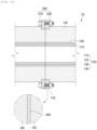
FIG. 1 is a perspective view illustrating a tube module according a first embodiment of the present invention,FIG. 2 is a front view ofFIG. 1 ,FIG. 3 is a side view ofFIG. 1 ,FIG. 4 is a cross-sectional view ofFIG. 1 , andFIG. 5 is a partially enlarged view ofFIG. 2 . -
FIG. 6 is a perspective view illustrating a tube assembly according to a sixth embodiment of the present invention,FIG. 7 is a side view ofFIG. 6 , andFIG. 8 is a partially cross-sectional view ofFIG. 6 . -
FIG. 9 is a cross-sectional view illustrating a tube module according to a second embodiment of the present invention. -
FIG. 10 is a partially enlarged view illustrating a tube module according to a third embodiment of the present invention. -
FIG. 11 is a see-through view illustrating a tube of a tube module according to a fourth embodiment of the present invention, andFIG. 12 is a see-through view exemplifying a connection state of the tube according to the fourth embodiment. -
FIG. 13 is a perspective view illustrating a tube of a tube module according to a fifth embodiment of the present invention, andFIGS. 14 and 15 are views exemplifying cross-sectional shapes of baffle coupling portions according to the fifth embodiment. -
FIG. 16 is a view illustrating examples of baffles applied in the tube module according to the fifth embodiment, andFIGS. 17 to 23 are views illustrating various examples of tubes to which baffles are coupled. - Hereinafter, embodiments of the present invention will be described in detail with reference to the accompanying drawings so as to be easily carried out by a person skilled in the art to which the present invention pertains. However, the present invention may be implemented in various different forms, and is not limited to the embodiments described herein. Also, in the drawings, parts irrelevant to the description will be omitted to clearly describe the present invention, and similar elements will be designated by similar reference numerals throughout the specification.
- As described in
FIGS. 1 to 5 , atube module 100 according to a first embodiment of the present invention includes atube 110 made of a ceramic material, aheat insulator 120 made of a ceramic material, asusceptor 130 provided between thetube 110 and theheat insulator 120, aflange 140 provided on each of both surfaces of the heat insulator, and areinforcing bar 150 that maintains strength and an outer shape of theheat insulator 120. - Meanwhile, the
flange 140 serves to connect a plurality of tube modules, in which a ceramic material is used, in a longitudinal direction. - The
tube 110 is made of a ceramic material and has a cylindrical shape with a bore so that a reaction raw material having a powder shape may be loaded therein. - Here, the
tube 110 made of the ceramic material is made of high-purity alumina, and accordingly, reaction with a reaction raw material accommodated within thetube 110 may be minimized. - Here, the
tube 110 may include at least one selected from the group consisting of oxide (e.g., alumina, zirconia, quartz, mullite), nitride (e.g., silicon nitride), and carbide (e.g., silicon carbide) among ceramic materials. - The
heat insulator 120 is made of a ceramic material and provided in a shape surrounding an outer circumferential surface of thetube 110, and absorbs heat generated from thetube 110 or thesusceptor 130 to prevent the heat from being diffused to the outside. - Meanwhile, the ceramic has high thermal resistance and is resistant to a strong acid or base and even to corrosive conditions. Accordingly, the
tube 110 and theheat insulator 120 made of the ceramic materials may prevent corrosion due to a reaction raw material, i.e., a positive electrode active material, and may also prevent the occurrence of pollution of the positive electrode active material due to the corrosion. - Here, the
heat insulator 120 may include at least one or two or more selected from the group consisting of quartz, mullite, and alumina among ceramic materials. - The
susceptor 130 is provided between thetube 110 and theheat insulator 120, and generates heat by microwaves to heat the reaction raw material accommodated in thetube 110. - Here, the
susceptor 130 is provided in plurality so as to be arranged equidistantly along an outer circumferential surface of thetube 110, and accordingly, thesusceptor 130 may be conveniently arranged on the outer circumferential surface of thetube 110. - Here, the
susceptor 130 has a long bar shape to be connected from one side of thetube 110 to the other side in the longitudinal direction (from a left end of the tube to a right end when viewed inFIG. 3 ), and accordingly, heat having uniform temperature may be generated along the longitudinal direction of thetube 110. - Particularly, the
susceptor 130 has a quadrangular cross-section, and accordingly, the contact surface between thetube 110 and thesusceptor 130 may be increased to increase force for fixing thesusceptor 130, and particularly, thesusceptor 130 may be prevented from rotating. - Meanwhile, an
extension part 131 having thermal insulating characteristics is further provided between the susceptor 130 and thesusceptor 130 arranged equidistantly on the outer circumferential surface of thetube 110, and theextension part 131 may insulate heat between the susceptor 130 and thesusceptor 130 to prevent the occurrence of nonuniform heating temperature, and particularly, the gap between the susceptor 130 and thesusceptor 130 may be constantly maintained. - Meanwhile, the
extension part 131 is formed integrally with theheat insulator 120, and accordingly, ease of manufacture may be achieved. - Meanwhile, the
susceptor 130 may include at least one selected from the group consisting of SiC, graphite, carbon nanotubes, carbon nanofibers, and graphene, and preferably, is formed of a SiC material. - The
flange 140 is for coupling and connecting a plurality of tube modules in the longitudinal direction, and is provided in each of both surfaces of the tube module in the longitudinal direction (the front surface and the rear surface when viewed inFIG. 1 ) and has a band shape provided along an edge of each of both the surfaces of theheat insulator 120. - Meanwhile, in the present invention, it is very difficult to manufacture the
tube 110 and theheat insulator 120 made of the ceramic materials with the lengths of several hundred mm, several thousand mm, or more due to the material characteristics. Accordingly, a tube module, in which thetube 110 and theheat insulator 120 made of the ceramic materials are applied, is manufactured to a certain length, and then, a plurality of tube modules are connected by using theflanges 140, thus obtaining a tube module in which the ceramic materials having several hundred mm or several thousand mm are applied. - Meanwhile, the
flange 140 is inserted into aninsertion groove 121 formed along an edge of each of both the surfaces of theheat insulator 120, and accordingly, adhesion force and coupling force between theflange 140 and theheat insulator 120 may be enhanced. Also, an adhesive or a sealant may be further included between theflange 140 and theinsertion groove 121, and accordingly, the coupling force between theflange 140 and theinsertion groove 121 may be significantly increased. - Also, an externally exposed surface of the
flange 140 and an externally exposed surface of theheat insulator 120 are positioned on the same horizontal line (on an X-line indicated inFIG. 4 ), and accordingly, when the plurality of thetube modules 100 are connected in the longitudinal direction, the entire corresponding surfaces of the corresponding tube modules may be brought into close contact with each other. - The at least one or more reinforcing
bars 150 are provided on the outer circumferential surface of the heat insulator and reinforce strength of the heat insulator. Here, the reinforcingbar 150 has one surface supported by theheat insulator 120 and both ends respectively coupled to theflanges 140 provided on both the surfaces of theheat insulator 120. Accordingly, the reinforcingbar 150 may stably reinforce the strength of theheat insulator 120 through connectivity with theflange 140. - Particularly, the reinforcing
bar 150 has a quadrangular cross-section, and accordingly, the reinforcingbar 150 coupled to theflange 140 may be prevented from rotating, and thus, the weakening of the coupling force between theflange 140 and the reinforcingbar 150 and the occurrence of foreign substances due to friction may be prevented. - Meanwhile, the
flange 140 and the reinforcingbar 150 are made of metal or ceramic materials, and accordingly, the strength of theflange 140 and the reinforcingbar 150 may be significantly enhanced, and thetube 110, theheat insulator 120, thesusceptors 130 may be stably protected from the outside. - Thus, the
tube module 100 having the above structure according to a first embodiment of the present invention includes the tube and the heat insulator made of the ceramic materials and the flanges respectively provided on both the surfaces of the heat insulator. Accordingly, the corrosion of the tube and the heat insulator due to the reaction raw material may be prevented, the pollution of the positive electrode active material may be prevented as the corrosion of the tube is prevented, and the tube module having a preset size may be obtained because the plurality of tube modules manufactured to certain sizes may be connected. Particularly, heat sources such as microwaves may be diversified. - Hereinafter, in describing another embodiment of the present invention, components having the same functions as those in the embodiment described above are given the same reference numerals, and their duplicated description will be omitted.
- As illustrated in
FIG. 9 , atube module 100 according to the second embodiment of the present invention has a structure enhancing a coupling force between atube 110 of atube module 100 and atube 110 of acorresponding tube module 100. - That is, a
coupling groove 111 is formed on one side surface of the tube 110 (the left surface of the tube when viewed inFIG. 9 ) along the circumferential surface, and acoupling protrusion 113 is formed on the other side surface (the right surface of the tube inFIG. 9 ) along the circumferential surface. - Thus, in the
tube module 100 according to the second embodiment of the present invention, when a plurality oftube modules 100 are arranged in the longitudinal direction,coupling grooves 111 andcoupling protrusions 113 of thetube modules 100 are arranged corresponding to each other. As a result, atube 110 of atube module 100 and atube 110 of acorresponding tube module 100 may be coupled and sealed through thecoupling groove 111 and thecoupling protrusion 113. - Meanwhile, an adhesive layer having thermal resistance may be further included between the
coupling groove 111 and thecoupling protrusion 113 coupled to each other, and accordingly, the sealing force between thecoupling groove 111 and thecoupling protrusion 113 may be significantly enhanced. - Meanwhile, the
coupling groove 111 and thecoupling protrusion 113 may be coupled in an interference fit manner or in a screw fastening manner. - As illustrated in
FIG. 10 , in atube module 100 according to the third embodiment of the present invention, an outer circumferential surface of atube 110 has anarrangement portion 115 on which each of a plurality ofsusceptors 130 is disposed. Thesusceptors 130 may be conveniently arranged on the outer circumferential surface of thetube 110 through thearrangement portions 115. - As one example, the
arrangement portion 115 is an arrangement groove recessed toward the inside of thetube 110, and thesusceptor 130 may be inserted into and disposed in the arrangement groove. - Thus, in the
tube module 100 according to the third embodiment of the present invention, the plurality ofsusceptors 130 may be conveniently installed on the outer circumferential surface of thetube 110 without a separate installation device, and thesusceptor 130 may be firmly prevented from moving to the outer circumferential surface of thetube 110. - Meanwhile, an adhesive layer having thermal resistance may be further included between the arrangement portion and the
susceptor 130, and the coupling force between the arrangement portion and thesusceptor 130 may be enhanced through the adhesive layer. - As illustrated in
FIG. 11 , atube module 100 according to the fourth embodiment of the present invention may include atube 110 having a structure in which an inner bore is inclined in one direction, for example, in a direction from one end of the tube to the other end. Here, thetube module 100 has the same structure and function of the tube modules described in the first embodiment to the fourth embodiment except that the bore inside thetube 110 is formed in an inclined structure, and thus, duplicated description will be omitted. - When the bore inside the tube is formed in the inclined structure as described above, the rotation degree of raw materials changes according to regions inside the tube during the rotation of the tube module, and thus, the mixing of the raw materials may be more uniformly performed compared to the tube in which the bore is formed in parallel.
- The inclined structure may be formed by differently forming the thickness of a tube
inner wall 110a along the longitudinal direction of thetube 110. That is, in thetube 110 according to the present invention, the thickness of the inner wall of the tube in the longitudinal direction may increase or decrease. - Also, it is preferable that an inclination angle α of the bore is formed less than an inclination angle of the tube module when the tube module is mounted to a horizontal rotary kiln, that is, an angle between the tube module and the ground of the kiln. This is because the raw material may flow backward or flowability may deteriorate, when the inclination angle of the bore is greater than the inclination angle of the tube module.
- Specifically, the bore may have a structure inclined at an angle of 1° to 10° with respect to an
outer wall 110b of the tube, preferably, at an angle of 3° to 5°. - Meanwhile, when a
tube assembly 10 is formed by using thetube modules 100 that include thetubes 110 in which the inner bores are formed in the inclined shapes as described above, neighboringtubes 110 may be connected as illustrated inFIG. 12 such that slopes of the inclination structures of the bores are different from each other. For example, as the tube modules are rotated at 180 degrees and alternately arranged and connected when the tube modules are assembled, he slopes of the bore inclination structures of the tube modules may become different from each other. - When the slopes of the bore inclination structures of the neighboring tube modules are different as described above, a difference in height of the raw material increases at a connection portion of the tube modules during the rotation of the tube assembly, and thus, the mixing effect of the raw material may be further improved.
- As illustrated in
FIG. 13 , atube module 100 according to the fifth embodiment of the present invention may include atube 110 that includes abaffle coupling portion 112 in an inner wall. Here, thetube module 100 has the same structure and function of the tube modules described in the first embodiment to the fourth embodiment except that thebaffle coupling portion 112 is formed in the inner wall of thetube 110, and thus, duplicated description will be omitted. - The
baffle coupling portion 112 is formed such that a baffle may be attached to and detached from, and it is sufficient to have a shape capable of inserting and separating the baffle and supporting the baffle when the baffle is inserted, and the shape thereof is not particularly limited. For example, thebaffle coupling portion 112 may have a groove shape extending in the longitudinal direction of thetube 110 and recessed in a direction from the inner wall to the outer wall as illustrated inFIG. 13 , but is not limited thereto. A shape such as a support rail protruding from the tube inner wall toward the bore is possible. The shape of the groove is not particularly limited. For example, the groove has a quadrangular cross-section as illustrated inFIG. 14 , or may have a T-shaped cross-section as illustrated inFIG. 15 . Although not illustrated in the drawings, the cross-section having a half circle, a triangle, a polygon, or the like is possible. - As the
baffle coupling portion 112, to and from which the baffle may be attached and detached, is provided in the inner wall of thetube 110 as described above, various types of the baffles may be attached and detached inside the tube in various arrangement configurations. Thus, the baffles capable of producing the best effects are selected and used according to the firing conditions and the types or contents of raw materials to be loaded. - In the
tube module 100, at least onebaffle 114 may be coupled to thebaffle coupling portion 112. It is sufficient that thebaffle 114 may induce uniform mixing of the raw material, and the shape thereof is not particularly limited. For example, thebaffle 114 may have a plate shape or a cross shape as illustrated inFIG. 16 , but is not limited thereto. Baffles having various shapes such as a half circle or a triangle may be used. Also, a distal end of thebaffle 114 inserted into thebaffle coupling portion 112 may have a cross-sectional shape corresponding to the shape of thebaffle coupling portion 112. For example, when thebaffle coupling portion 112 has the T-shaped cross-section as illustrated inFIG. 15 , the distal end of thebaffle 114 inserted into thebaffle coupling portion 112 may also have the T-shape cross-section. - Meanwhile, it is preferable that the
baffle 114 is made of a ceramic material. When thebaffle 114 is made of a ceramic material, corrosion due to reaction with a reaction raw material and pollution of a raw material may be prevented, and microwaves may be transmitted therethrough. - Meanwhile, the
baffle 114 may be applied in thetube module 100 in various arrangement configurations.FIGS. 17 to 23 illustrate examples of tubes in which baffles are coupled. - According to one example, a
tube 110 of the present invention includes one pair or more ofbaffle coupling portions 112a formed at positions symmetric with respect to a central axis of thetube 110 as illustrated inFIGS. 17 and18 , and onebaffle 114 may be coupled to the pair of thebaffle coupling portions 112a. Here, thebaffle 114 may be coupled so as to be disposed in a direction parallel to the longitudinal direction of thetube 110 as illustrated inFIG. 17 , or may be coupled so as to be disposed in a direction perpendicular to the longitudinal direction of thetube 110 as illustrated inFIG. 18 . - According to another example, a
tube 110 of the present invention includes two pairs ofbaffle coupling portions tube 110 as illustrated inFIG. 19 , and abaffle 114 having a cross-shaped cross-section may be coupled to the two pairs of the baffle coupling portions. - Meanwhile,
FIGS. 17 to 19 illustrate that thebaffle 114 has the width corresponding to the inner diameter of thetube 110 and has the length corresponding to the length of the tube, but are not limited thereto. Abaffle 114 having a width d smaller than an inner diameter R of atube 110 may be applied as illustrated inFIG. 20 , and a baffle having a length 1 smaller than a length L of the tube may also be applied as illustrated inFIG. 21 . - Meanwhile,
FIGS. 17 to 20 illustrate that onebaffle 114 is applied in thetube 110, but are not limited thereto. Two or more baffles may be coupled to onetube 110.FIGS. 21 to 23 illustrate examples of tubes in which two or more baffles are applied. - According to one example, in a
tube 110 of the present invention as illustrated inFIG. 21 , plate-shapedbaffles 114, which have a width d smaller than an inner diameter R of the tube and a length 1 smaller than a length L of the tube, may be spaced a constant distance along the longitudinal direction of the tube and coupled to bafflecoupling portions 112. For example, thebaffles 114 have a width less than or equal to 1/2 of the inner diameter R of the tube, and one or more baffles are coupled to each ofbaffle coupling portions baffle coupling portion 112c positioned in an upper portion of the tube in the drawing and thebaffle coupling portion 112d positioned in a lower portion of the tube in the drawing. Here, the baffles coupled to the upper baffle coupling portion and the baffles coupled to the lower baffle coupling portion may be disposed so as to be offset from each other along the longitudinal direction of the tube as illustrated inFIG. 21 , or may be disposed at corresponding positions. - According to another example, in a
tube 110 of the present invention, two or more baffles may be coupled to a baffle coupling portion in different arrangements. For example, as illustrated inFIG. 22 , a baffle may be coupled in one region inside the tube so as to be disposed in parallel to the longitudinal direction of the tube, and a baffle may be coupled in the other region inside the tube so as to be disposed perpendicularly to the longitudinal direction of the tube. - According to another example, in a
tube 110 of the present invention, two ormore baffles coupling portions FIG. 23 , a baffle having a cross shape may be coupled in one region inside the tube, a baffle having a plate shape may be coupled in another region inside the tube so as to be disposed in parallel to the longitudinal direction of the tube, and a baffle having a plate shape may be coupled in the other region inside the tube so as to be disposed perpendicularly to the longitudinal direction of the tube. - Meanwhile, when two or more baffles are applied in one baffle coupling portion, a fixing
member 116 may be further provided as needed so as to fix the baffles to thebaffle coupling portions FIG. 21 ). The fixingmember 116 serves to fix the positions of thebaffles 114 and adjust a spaced distance between thebaffles 114. Specifically, thebaffle 114 may be supported by the fixingmember 116 to prevent the baffle from moving left and right, and a distance between the baffles may be adjusted according to the length of the fixingmember 116. Also, although not illustrated in the drawing, the fixing member may be applied even in a baffle coupling portion to which a baffle is not coupled. When the fixing member is applied in the baffle coupling portion to which the baffle is not coupled, a raw material may be prevented from being stuck in an empty baffle. - Although the examples of the tubes, in which the baffles according to the present invention are applied, have been described with reference to the drawings, the tube modules according to the present invention are not limited to those illustrated in the drawings but may be modified into various shapes and/or arrangements.
- In the case of a horizontal rotary kiln according to the related art, when a loading volume exceeds 10 volume! of a tube, raw materials slide along a tube inner wall during rotation of the tube, and the raw materials are not appropriately mixed. Thus, firing is not performed uniformly, and an amount of raw materials to be loaded is limited, and accordingly, there is a limitation in increasing the production. However, when the
baffle 114 is disposed inside the tube as in the present invention, the bore inside thetube 110 is partitioned by thebaffle 114, and raw materials collide with thebaffle 114 and then drop during the rotation of the tube module. Thus, the phenomenon in which the raw materials slide along the tube inner wall is reduced, and the raw materials are actively mixed. Accordingly, the firing may be performed uniformly even in the case where a larger amount of raw materials are loaded than in the related art. - Also, when two or more baffles having different shapes and/or arrangements are included in one tube, the degree of mixing the raw material may be changed according to the firing conditions inside the tube, thus further enhancing the firing quality. For example, in a front end portion of the tube in which the temperature rises, several baffles having smaller widths may be used, or a large baffle such as a cross-shaped baffle having a large area in contact with raw materials may be used, thereby actively mixing the raw materials. In a rear end portion of the tube in which the temperature drops, a plate-shaped baffle having a relatively small area in contact with raw materials or a baffle having a small width may be used, thereby minimizing dusts and damages to fired products.
- As illustrated in
FIGS. 6 to 8 , atube assembly 10 according to the sixth embodiment of the present invention includes: a plurality oftube modules 100 arranged in a longitudinal direction; and acoupling member 200 which connects and couples the plurality oftube modules 100 arranged in the longitudinal direction. - Each of the
tube modules 100 includes atube 110 having a bore and made of a ceramic material, aheat insulator 120 surrounding an outer circumferential surface of thetube 110 and made of a ceramic material, asusceptor 130 disposed between thetube 110 and theheat insulator 120, aflange 140 provided along an edge of each of both surfaces of theheat insulator 120 and formed in a band shape, and a reinforcingbar 150 reinforcing strength of theheat insulator 120. - Here, the
tube module 100 has the same structure and function as the tube modules described in the first embodiment to the fifth embodiment, and accordingly, duplicated description will be omitted. - The
coupling member 200 is for connecting a plurality of tube modules in the longitudinal direction as illustrated inFIG. 8 , and couples aflange 140 of atube module 100 and aflange 140 of acorresponding tube module 100, thus connecting the plurality oftube modules 100 in the longitudinal direction. - That is, referring to
FIG. 8 , thecoupling member 200 includes acoupling bolt 210 which passes through aflange 140 of one side-tube module 100 and aflange 140 of the other side-tube module 100 which are in close contact with each other, and acoupling nut 220 which is coupled to thecoupling bolt 210 that passes through theflange 140 of the other side-tube module 100. The plurality oftube modules 100 may be connected in the longitudinal direction through the coupling between thecoupling bolt 210 and thecoupling nut 220. - Particularly, an
adhesive layer 300 having thermal resistance may be further included between the one side-tube module 100 and the other side-tube module 100 which are in close surface contact with each other, and theadhesive layer 300 may significantly enhance the bonding force and sealing force between the one side-tube module 100 and the other side-tube module 100 which are in close surface contact with each other. - Thus, in the
tube assembly 10 having the above structure according to the sixth embodiment of the present invention, themodule tube 110, which includes thetube 110 and theheat insulator 120 made of the ceramic materials, may be manufactured to a length of several hundred or several thousand mm or more. Accordingly, thetube module 100 may be configured to process a large amount of the reaction raw material, i.e., the positive electrode active material. - The positive electrode active material firing apparatus according to the seventh embodiment of the present invention includes a tube assembly which is equipped with a plurality of
tube modules 100 and acoupling member 200 connecting and coupling the plurality oftube modules 100 in the longitudinal direction. - Here, the tube module assembly may have the same structure as the tube assembly described in the sixth embodiment, and accordingly, duplicated descriptions will be omitted.
- The positive electrode active material firing apparatus may be a horizontal rotary firing apparatus that rotates about a rotary axis parallel to the longitudinal direction of the
tube module 100 during the firing. - In the positive electrode active material firing apparatus according to the present invention, the tube assembly, in which the plurality of tube modules made of the ceramic materials are connected in the longitudinal direction, is applied, and thus, the large amount of the positive electrode active material may be processed, and accordingly, the working efficiency may be significantly improved and working time may be significantly reduced. Particularly, the positive electrode active materials having uniform quality may be obtained.
- Also, the tube and the heat insulator of the positive electrode active material firing apparatus of the present invention are made of the ceramic materials, and thus, the microwave heat source may be applied.
- The scope of the present invention is defined by the appended claims rather than the foregoing description, and various embodiments derived from the meaning and scope of the claims and their equivalent concepts are also possible.
Claims (24)
- A tube module comprising:a tube having a bore and made of a ceramic material;a heat insulator surrounding an outer circumferential surface of the tube and made of a ceramic material; anda flange provided along an edge of each of both surfaces of the heat insulator and formed in a band shape.
- The tube module of claim 1, further comprising a plurality of susceptors arranged along the outer circumferential surface of the tube between the tube and the heat insulator.
- The tube module of claim 2, wherein each of the susceptors has a long bar shape to be connected from one side of the tube to the other side in a longitudinal direction.
- The tube module of claim 1, wherein the heat insulator has an insertion groove which is formed along the edge of each of both the surfaces and into which the flange is inserted.
- The tube module of claim 4, wherein an externally exposed surface of the flange and an externally exposed surface of the heat insulator are positioned on the same horizontal line.
- The tube module of claim 2, wherein the outer circumferential surface of the tube has an arrangement portion on which each of the plurality of susceptors is disposed.
- The tube module of claim 1, further comprising one or more reinforcing bars which are provided on an outer circumferential surface of the heat insulator and reinforce strength of the heat insulator.
- The tube module of claim 7, wherein each of the reinforcing bars has one surface supported by the heat insulator and both ends respectively coupled to the flanges provided on both the surfaces of the heat insulator.
- The tube module of claim 7, wherein the flange or the reinforcing bar is made of a metal or ceramic material.
- The tube module of claim 1, wherein the tube has a structure in which the bore is inclined in one direction.
- The tube module of claim 10, wherein a thickness of an inner wall of the tube increases or decreases in a longitudinal direction.
- The tube module of claim 10, wherein the tube module is applied to a horizontal rotary kiln, and
the inclination angle of the bore is less than an inclination angle of the tube module when the tube module is mounted to the horizontal rotary kiln. - The tube module of claim 10, wherein the bore has a structure inclined at an angle of 1° to 10° with respect to an outer wall of the tube.
- The tube module of claim 1, wherein an inner wall of the tube has at least one baffle coupling portion to and from which a baffle is attached and detached.
- The tube module of claim 14, wherein the baffle coupling portion has a groove shape recessed in a direction from the inner wall of the tube toward an outer wall and extending in a longitudinal direction of the tube.
- The tube module of claim 14, wherein at least one baffle is coupled to the baffle coupling portion.
- The tube module of claim 14, wherein a fixing member configured to fix the baffle is coupled to the baffle coupling portion.
- The tube module of claim 1, wherein two or more baffles having different shapes or arrangement forms are coupled to inside of the tube.
- A tube assembly comprising:a plurality of tube modules arranged in a longitudinal direction; anda coupling member which connects and couples the plurality of tube modules arranged in the longitudinal direction,wherein each of the tube modules is the tube module of any one of claims 1 to 18, andthe coupling member couples the flange of the tube module to the flange of the corresponding tube module and connects the plurality of tube modules in the longitudinal direction.
- The tube assembly of claim 19, wherein the tube module further comprises the reinforcing bar that reinforces strength of the heat insulator.
- The tube assembly of claim 19, further comprising an adhesive layer between the tube module and the corresponding tube module.
- The tube assembly of claim 19, wherein the tube has a coupling groove formed on one side along a circumferential surface and a coupling protrusion formed on the other side along the circumferential surface, and the tube of the tube module and the tube of the corresponding tube module are coupled and sealed through the coupling groove and the coupling protrusion.
- The tube assembly of claim 22, wherein the coupling groove and the coupling protrusion are coupled through a screw coupling manner.
- A positive electrode active material firing apparatus comprising the tube assembly of claim 19.
Applications Claiming Priority (4)
| Application Number | Priority Date | Filing Date | Title |
|---|---|---|---|
| KR1020200068508A KR102819968B1 (en) | 2020-06-05 | 2020-06-05 | Tube module and tube assembly comprising the same |
| KR1020200125180A KR20220041646A (en) | 2020-09-25 | 2020-09-25 | Tube module and tube assembly comprising the same |
| KR1020200125179A KR102847358B1 (en) | 2020-09-25 | 2020-09-25 | Tube module and tube assembly comprising the same |
| PCT/KR2021/007045 WO2021246831A1 (en) | 2020-06-05 | 2021-06-04 | Tube module and tube assembly comprising same |
Publications (2)
| Publication Number | Publication Date |
|---|---|
| EP4137771A1 true EP4137771A1 (en) | 2023-02-22 |
| EP4137771A4 EP4137771A4 (en) | 2023-11-08 |
Family
ID=78830477
Family Applications (1)
| Application Number | Title | Priority Date | Filing Date |
|---|---|---|---|
| EP21818531.2A Pending EP4137771A4 (en) | 2020-06-05 | 2021-06-04 | PIPE MODULE AND PIPE ARRANGEMENT WITH IT |
Country Status (5)
| Country | Link |
|---|---|
| US (1) | US12455116B2 (en) |
| EP (1) | EP4137771A4 (en) |
| JP (1) | JP7501978B2 (en) |
| CN (1) | CN115667827A (en) |
| WO (1) | WO2021246831A1 (en) |
Family Cites Families (36)
| Publication number | Priority date | Publication date | Assignee | Title |
|---|---|---|---|---|
| US2288372A (en) * | 1938-03-24 | 1942-06-30 | Rump Heinrich | Insert in rotary furnaces |
| FR2473578B1 (en) * | 1980-01-11 | 1986-03-21 | Creusot Loire | |
| JPS6460988A (en) | 1987-08-31 | 1989-03-08 | Dainippon Screen Mfg | Heat treatment furnace for semiconductor substrate |
| JPH01300187A (en) | 1988-05-27 | 1989-12-04 | Ishikawajima Harima Heavy Ind Co Ltd | Special atmosphere furnace |
| US5038019A (en) * | 1990-02-06 | 1991-08-06 | Thermtec, Inc. | High temperature diffusion furnace |
| JPH0743219B2 (en) * | 1992-01-28 | 1995-05-15 | 功 久保山 | Rotary kiln |
| GB2263967A (en) | 1992-02-07 | 1993-08-11 | Electricity Ass Tech | Microwave furnace |
| KR950010199B1 (en) | 1992-06-05 | 1995-09-11 | 현대전자산업주식회사 | Chemical Vapor Deposition Tube |
| JP3132267B2 (en) * | 1993-11-02 | 2001-02-05 | 株式会社村田製作所 | Ceramic heat treatment equipment |
| JP3236238B2 (en) | 1997-03-28 | 2001-12-10 | 株式会社黒松電機製作所 | Induction heating furnace |
| JP3787216B2 (en) | 1997-04-16 | 2006-06-21 | 株式会社アクトリー | Waste carbonization and reduction equipment |
| DE19752728C2 (en) | 1997-11-28 | 1999-11-04 | Karlsruhe Forschzent | Rotary tube furnace heated by microwaves |
| JP3611318B2 (en) | 1999-07-22 | 2005-01-19 | 三菱重工業株式会社 | Microwave rotary dryer |
| US20050038019A1 (en) | 2001-10-29 | 2005-02-17 | Beck James P. | Hydroxy substituted amides for the treatment of alzheimer's disease |
| JP2003187947A (en) * | 2001-12-13 | 2003-07-04 | Three M Innovative Properties Co | Manufacturing device of ceramic bead |
| JP2003292964A (en) | 2002-04-02 | 2003-10-15 | Meidensha Corp | Apparatus and facility for heat treatment |
| KR100500699B1 (en) | 2003-01-28 | 2005-07-12 | 한국과학기술원 | Synthesis Method of Cathode Powder for Lithium Secondary Battery by Microwave Heating |
| JP2005098553A (en) | 2003-09-22 | 2005-04-14 | Noritake Co Ltd | Heat exchanger |
| KR100590658B1 (en) | 2004-04-28 | 2006-06-19 | 모딘코리아 유한회사 | Header pipe of car evaporator |
| KR200391785Y1 (en) | 2005-03-03 | 2005-08-09 | 송재옥 | Rotary Kiln Having Internal Plowshare |
| MX2013003852A (en) | 2010-10-07 | 2013-07-03 | Milt D Mathis | Microwave rotary kiln. |
| CN102889787B (en) | 2011-07-22 | 2016-01-27 | 深圳市沃尔核材股份有限公司 | Environment-friendly and energy-efficient heating furnace |
| JP2013112704A (en) | 2011-11-25 | 2013-06-10 | Chisaki:Kk | Pyrolysis apparatus for combustible matter-containing raw material |
| KR101350039B1 (en) | 2012-06-08 | 2014-01-13 | 닛신 엔지니어링 가부시키가이샤 | Rotary agitation type heat treatment apparatus |
| JP5964899B2 (en) | 2014-08-07 | 2016-08-03 | 杉山重工株式会社 | Rotary kiln |
| GB2543688B (en) * | 2015-03-05 | 2017-08-30 | Standard Gas Ltd | Pyrolysis retort methods and apparatus |
| CN105157424B (en) * | 2015-09-16 | 2017-04-05 | 苏州汇科机电设备有限公司 | The high-temperature vacuum sintering furnace heated using graphite heating rod |
| CN205207983U (en) * | 2015-12-03 | 2016-05-04 | 浙江万马高分子材料有限公司 | Metal pipeline flange with function is carried to good PE granule |
| CN107883761A (en) * | 2017-12-06 | 2018-04-06 | 江苏凤谷节能科技有限公司 | Rotary kiln inner-tube structure |
| KR102282277B1 (en) | 2018-09-03 | 2021-07-28 | 주식회사 엘지화학 | Microwave furnace and plasticity method of positive electrode active material using the same |
| KR102752275B1 (en) | 2018-12-05 | 2025-01-10 | 엘지디스플레이 주식회사 | Display device and data output circuit |
| KR102054946B1 (en) | 2019-04-08 | 2019-12-12 | (주)현대에스엔티 | Microwave electric furnace |
| KR102225798B1 (en) | 2019-04-26 | 2021-03-11 | 한국과학기술연구원 | Aquifer storage and recovery system including absorbent in injection or recovery pipe |
| KR20200125180A (en) | 2019-04-26 | 2020-11-04 | (주)디앤엠솔루션즈 | Power data cable connector for preventing disconnection and short |
| CN110375544A (en) * | 2019-07-19 | 2019-10-25 | 江苏凤谷节能科技有限公司 | A kind of ceramic liner Rotary kiln installation structure |
| US12257629B2 (en) * | 2020-01-09 | 2025-03-25 | Tundra COmpoistes, LLC | Apparatus and methods for sintering |
-
2021
- 2021-06-04 WO PCT/KR2021/007045 patent/WO2021246831A1/en not_active Ceased
- 2021-06-04 CN CN202180035888.0A patent/CN115667827A/en active Pending
- 2021-06-04 US US17/926,773 patent/US12455116B2/en active Active
- 2021-06-04 EP EP21818531.2A patent/EP4137771A4/en active Pending
- 2021-06-04 JP JP2022570194A patent/JP7501978B2/en active Active
Also Published As
| Publication number | Publication date |
|---|---|
| EP4137771A4 (en) | 2023-11-08 |
| US20230213281A1 (en) | 2023-07-06 |
| CN115667827A (en) | 2023-01-31 |
| US12455116B2 (en) | 2025-10-28 |
| WO2021246831A1 (en) | 2021-12-09 |
| JP2023526363A (en) | 2023-06-21 |
| JP7501978B2 (en) | 2024-06-18 |
Similar Documents
| Publication | Publication Date | Title |
|---|---|---|
| CN117637991B (en) | A pole piece, an electrode assembly and a battery | |
| CN103155266B (en) | Battery pack with excellent cooling efficiency | |
| EP2430691B1 (en) | Li -ION BATTERY WITH POROUS ANODE SUPPORT | |
| CN108063273B (en) | Single cell of fuel cell | |
| US20210151732A1 (en) | Slot die for manufacturing rechargeable battery electrode | |
| EP3716365A1 (en) | Cathode and secondary battery comprising same cathode | |
| EP4212809A1 (en) | Rotary kiln | |
| KR102705295B1 (en) | Lithium secondary battery | |
| KR102859832B1 (en) | Tube module and tube assembly comprising the same | |
| US12455116B2 (en) | Tube module and tube assembly including same | |
| EP4279186B1 (en) | Air discharge apparatus and drying device | |
| CN211848132U (en) | Electrode slice, slide glass device and coating system | |
| US20250091085A1 (en) | Coating die head and coating apparatus | |
| US20190229329A1 (en) | Electrode for secondary battery and manufacturing method therefor | |
| KR102847358B1 (en) | Tube module and tube assembly comprising the same | |
| KR102113294B1 (en) | Plasma generator having improved insulation part | |
| KR102834717B1 (en) | Silicon oxide anode material manufacturing device and manufacturing method for lithium secondary batteries | |
| KR20210151542A (en) | Tube module and tube assembly comprising the same | |
| KR20220041646A (en) | Tube module and tube assembly comprising the same | |
| WO2024178617A1 (en) | Graphitization furnace and battery production system | |
| KR20220010385A (en) | Heat tube module | |
| CN115052687B (en) | Coating device | |
| CN110890446B (en) | Graphite boat sleeve and graphite boat | |
| KR102808083B1 (en) | Lithium secondary battery, battery module and battary pack | |
| CN223134586U (en) | Graphite boat supporting structure and PECVD coating equipment |
Legal Events
| Date | Code | Title | Description |
|---|---|---|---|
| STAA | Information on the status of an ep patent application or granted ep patent |
Free format text: STATUS: THE INTERNATIONAL PUBLICATION HAS BEEN MADE |
|
| PUAI | Public reference made under article 153(3) epc to a published international application that has entered the european phase |
Free format text: ORIGINAL CODE: 0009012 |
|
| STAA | Information on the status of an ep patent application or granted ep patent |
Free format text: STATUS: REQUEST FOR EXAMINATION WAS MADE |
|
| 17P | Request for examination filed |
Effective date: 20221115 |
|
| AK | Designated contracting states |
Kind code of ref document: A1 Designated state(s): AL AT BE BG CH CY CZ DE DK EE ES FI FR GB GR HR HU IE IS IT LI LT LU LV MC MK MT NL NO PL PT RO RS SE SI SK SM TR |
|
| DAV | Request for validation of the european patent (deleted) | ||
| DAX | Request for extension of the european patent (deleted) | ||
| A4 | Supplementary search report drawn up and despatched |
Effective date: 20231009 |
|
| RIC1 | Information provided on ipc code assigned before grant |
Ipc: F27B 17/00 20060101ALI20231002BHEP Ipc: F27B 7/08 20060101ALI20231002BHEP Ipc: F27B 7/04 20060101ALI20231002BHEP Ipc: H01M 4/36 20060101ALI20231002BHEP Ipc: F27B 7/16 20060101ALI20231002BHEP Ipc: F27B 7/02 20060101ALI20231002BHEP Ipc: F27B 7/34 20060101ALI20231002BHEP Ipc: F27B 7/10 20060101ALI20231002BHEP Ipc: F27B 7/28 20060101AFI20231002BHEP |