EP4137765A1 - Volatilization device and storage device - Google Patents
Volatilization device and storage device Download PDFInfo
- Publication number
- EP4137765A1 EP4137765A1 EP20963306.4A EP20963306A EP4137765A1 EP 4137765 A1 EP4137765 A1 EP 4137765A1 EP 20963306 A EP20963306 A EP 20963306A EP 4137765 A1 EP4137765 A1 EP 4137765A1
- Authority
- EP
- European Patent Office
- Prior art keywords
- cavity
- color
- air outlet
- annular rib
- volatilization device
- Prior art date
- Legal status (The legal status is an assumption and is not a legal conclusion. Google has not performed a legal analysis and makes no representation as to the accuracy of the status listed.)
- Granted
Links
Images



Classifications
-
- F—MECHANICAL ENGINEERING; LIGHTING; HEATING; WEAPONS; BLASTING
- F25—REFRIGERATION OR COOLING; COMBINED HEATING AND REFRIGERATION SYSTEMS; HEAT PUMP SYSTEMS; MANUFACTURE OR STORAGE OF ICE; LIQUEFACTION SOLIDIFICATION OF GASES
- F25D—REFRIGERATORS; COLD ROOMS; ICE-BOXES; COOLING OR FREEZING APPARATUS NOT OTHERWISE PROVIDED FOR
- F25D17/00—Arrangements for circulating cooling fluids; Arrangements for circulating gas, e.g. air, within refrigerated spaces
- F25D17/04—Arrangements for circulating cooling fluids; Arrangements for circulating gas, e.g. air, within refrigerated spaces for circulating air, e.g. by convection
- F25D17/042—Air treating means within refrigerated spaces
-
- A—HUMAN NECESSITIES
- A61—MEDICAL OR VETERINARY SCIENCE; HYGIENE
- A61L—METHODS OR APPARATUS FOR STERILISING MATERIALS OR OBJECTS IN GENERAL; DISINFECTION, STERILISATION OR DEODORISATION OF AIR; CHEMICAL ASPECTS OF BANDAGES, DRESSINGS, ABSORBENT PADS OR SURGICAL ARTICLES; MATERIALS FOR BANDAGES, DRESSINGS, ABSORBENT PADS OR SURGICAL ARTICLES
- A61L9/00—Disinfection, sterilisation or deodorisation of air
- A61L9/015—Disinfection, sterilisation or deodorisation of air using gaseous or vaporous substances, e.g. ozone
- A61L9/04—Disinfection, sterilisation or deodorisation of air using gaseous or vaporous substances, e.g. ozone using substances evaporated in the air without heating
-
- F—MECHANICAL ENGINEERING; LIGHTING; HEATING; WEAPONS; BLASTING
- F25—REFRIGERATION OR COOLING; COMBINED HEATING AND REFRIGERATION SYSTEMS; HEAT PUMP SYSTEMS; MANUFACTURE OR STORAGE OF ICE; LIQUEFACTION SOLIDIFICATION OF GASES
- F25D—REFRIGERATORS; COLD ROOMS; ICE-BOXES; COOLING OR FREEZING APPARATUS NOT OTHERWISE PROVIDED FOR
- F25D29/00—Arrangement or mounting of control or safety devices
- F25D29/005—Mounting of control devices
-
- A—HUMAN NECESSITIES
- A61—MEDICAL OR VETERINARY SCIENCE; HYGIENE
- A61L—METHODS OR APPARATUS FOR STERILISING MATERIALS OR OBJECTS IN GENERAL; DISINFECTION, STERILISATION OR DEODORISATION OF AIR; CHEMICAL ASPECTS OF BANDAGES, DRESSINGS, ABSORBENT PADS OR SURGICAL ARTICLES; MATERIALS FOR BANDAGES, DRESSINGS, ABSORBENT PADS OR SURGICAL ARTICLES
- A61L2209/00—Aspects relating to disinfection, sterilisation or deodorisation of air
- A61L2209/10—Apparatus features
- A61L2209/11—Apparatus for controlling air treatment
-
- A—HUMAN NECESSITIES
- A61—MEDICAL OR VETERINARY SCIENCE; HYGIENE
- A61L—METHODS OR APPARATUS FOR STERILISING MATERIALS OR OBJECTS IN GENERAL; DISINFECTION, STERILISATION OR DEODORISATION OF AIR; CHEMICAL ASPECTS OF BANDAGES, DRESSINGS, ABSORBENT PADS OR SURGICAL ARTICLES; MATERIALS FOR BANDAGES, DRESSINGS, ABSORBENT PADS OR SURGICAL ARTICLES
- A61L2209/00—Aspects relating to disinfection, sterilisation or deodorisation of air
- A61L2209/10—Apparatus features
- A61L2209/13—Dispensing or storing means for active compounds
-
- A—HUMAN NECESSITIES
- A61—MEDICAL OR VETERINARY SCIENCE; HYGIENE
- A61L—METHODS OR APPARATUS FOR STERILISING MATERIALS OR OBJECTS IN GENERAL; DISINFECTION, STERILISATION OR DEODORISATION OF AIR; CHEMICAL ASPECTS OF BANDAGES, DRESSINGS, ABSORBENT PADS OR SURGICAL ARTICLES; MATERIALS FOR BANDAGES, DRESSINGS, ABSORBENT PADS OR SURGICAL ARTICLES
- A61L2209/00—Aspects relating to disinfection, sterilisation or deodorisation of air
- A61L2209/20—Method-related aspects
- A61L2209/21—Use of chemical compounds for treating air or the like
-
- F—MECHANICAL ENGINEERING; LIGHTING; HEATING; WEAPONS; BLASTING
- F25—REFRIGERATION OR COOLING; COMBINED HEATING AND REFRIGERATION SYSTEMS; HEAT PUMP SYSTEMS; MANUFACTURE OR STORAGE OF ICE; LIQUEFACTION SOLIDIFICATION OF GASES
- F25D—REFRIGERATORS; COLD ROOMS; ICE-BOXES; COOLING OR FREEZING APPARATUS NOT OTHERWISE PROVIDED FOR
- F25D2317/00—Details or arrangements for circulating cooling fluids; Details or arrangements for circulating gas, e.g. air, within refrigerated spaces, not provided for in other groups of this subclass
- F25D2317/04—Treating air flowing to refrigeration compartments
- F25D2317/041—Treating air flowing to refrigeration compartments by purification
-
- F—MECHANICAL ENGINEERING; LIGHTING; HEATING; WEAPONS; BLASTING
- F25—REFRIGERATION OR COOLING; COMBINED HEATING AND REFRIGERATION SYSTEMS; HEAT PUMP SYSTEMS; MANUFACTURE OR STORAGE OF ICE; LIQUEFACTION SOLIDIFICATION OF GASES
- F25D—REFRIGERATORS; COLD ROOMS; ICE-BOXES; COOLING OR FREEZING APPARATUS NOT OTHERWISE PROVIDED FOR
- F25D2500/00—Problems to be solved
- F25D2500/06—Stock management
-
- G—PHYSICS
- G01—MEASURING; TESTING
- G01N—INVESTIGATING OR ANALYSING MATERIALS BY DETERMINING THEIR CHEMICAL OR PHYSICAL PROPERTIES
- G01N21/00—Investigating or analysing materials by the use of optical means, i.e. using sub-millimetre waves, infrared, visible or ultraviolet light
- G01N21/75—Systems in which material is subjected to a chemical reaction, the progress or the result of the reaction being investigated
- G01N21/77—Systems in which material is subjected to a chemical reaction, the progress or the result of the reaction being investigated by observing the effect on a chemical indicator
- G01N21/78—Systems in which material is subjected to a chemical reaction, the progress or the result of the reaction being investigated by observing the effect on a chemical indicator producing a change of colour
- G01N21/783—Systems in which material is subjected to a chemical reaction, the progress or the result of the reaction being investigated by observing the effect on a chemical indicator producing a change of colour for analysing gases
Definitions
- the present application relates to the technical field of food preservation, in particular to a volatilization device and a storage device.
- a refrigerator will breed bacteria after a period of use, resulting in odor.
- some refrigerators will be installed with sterilization boxes.
- a lid of the sterilization box has a plurality of vent holes, and the sterilization box is placed with a slow-release agent wrapped by a non-woven fabric, such as an adsorbed solid chlorine dioxide slow-release agent.
- Chlorine dioxide slow-release agent absorbs water in air through the vent holes, and then produces chlorine dioxide gas.
- Chlorine dioxide gas can kill viruses, bacteria, protozoa, algae, fungi and various spores and spore-forming bacteriophages, it also does not react with organic matter by chlorination, and does not produce mutagenic, carcinogenic and teratogenic substances or other toxic substances.
- a speed of the chlorine dioxide slow-release agent releasing chlorine dioxide gas is related to a temperature and humidity of the surrounding environment. The higher the temperature or humidity of the surrounding environment, the more water the chlorine dioxide slow-release agent absorbs, and the faster the chlorine dioxide gas is released. However, with the passage of time, the ability of chlorine dioxide slow-release agent releasing chlorine dioxide gas will gradually weaken until it completely fails. Due to the vagaries of the temperature and humidity of the surrounding environment, the service life of chlorine dioxide slow-release agent is difficult to predict. In addition, the concentration of chlorine dioxide gas is not high under normal conditions, so it is difficult for users to determine whether the chlorine dioxide slow-release agent has failed by smelling it, resulting in users unable to replace it in time.
- An objective of the present application is to solve at least one of the problems existing in the related art.
- One of the objectives of the embodiments of the present application is to provide a volatilization device that can determine the validity of an object to be stored, so that users can replace it in time.
- the volatilization device fixes the color-changing member on the housing, exposes a side of the color-changing member to the cavity of the housing, and makes another side of the color-changing member visible from an outer wall of the housing, and then users can determine a validity of an object to be stored in the cavity by observing a color-changing member of the color-changing member, which facilitates users to change the in time.
- an observation window communicated with the cavity is provided on the housing, and the color-changing member is embedded in the observation window.
- the observation window is further embedded with a transparent plate, and the transparent plate is provided on a side of the color-changing member away from the cavity.
- the color-changing member is embedded in the air outlet, and a projection area of the color-changing member on the air outlet is smaller than an area of the air outlet.
- the color-changing member is gelatin
- the target gas is chlorine dioxide gas
- the volatilization device further includes: a first annular rib, provided in the cavity to divide the cavity into an accommodation cavity and an annular cavity distributed inside and outside, where the accommodation cavity is provided on an inner side of the annular cavity, the first annular rib is provided with a first vent hole communicating the accommodation cavity with the annular cavity, and the first vent hole is provided separately with the air outlet.
- the volatilization device further includes: a partition plate, provided in the annular cavity to divide the annular cavity into two buffer cavities distributed in front and back, where the partition plate is provided with a second vent hole communicating the two buffer cavities; and the accommodation cavity is communicated with one of the two buffer cavities through the first vent hole, and another of the two buffer cavities is communicated with the air outlet.
- the first vent hole is a notch formed at a first side edge of the first annular rib, and the air outlet is provided near a second side edge of the first annular rib located opposite to the first side edge of the first annular rib.
- an inner wall of the housing facing the notch is provided with a baffle plate opposite to the notch, and the baffle plate is located in the accommodation cavity, a free end of the baffle plate extends toward the second side edge of the first annular rib, an extension length of the baffle plate is not less than a height of the notch, and a gap is provided between a side wall of the baffle plate facing the first annular rib and the first annular rib.
- the housing includes:
- the air outlet is formed on a side wall of the back cover and is located at an edge of the back cover away from the front cover, and the color-changing member is fixed on the front cover and/or the air outlet.
- a side of the front cover facing the back cover is provided with a second annular rib, the second annular rib extends into the annular cavity, and the second annular rib closes to a side wall of the back cover.
- a side wall of the annular cavity is provided with a plurality of wedge-shaped protrusions
- a side of the front cover facing the back cover is provided with a plurality of first clamping hooks corresponding to the wedge-shaped protrusions in one-to-one correspondence on a, and the first clamping hook clamps with the corresponding wedge-shaped protrusion.
- a side of the front cover facing the back cover is provided with a plurality of clamping buckles, a placement space of an object to be stored is formed among the plurality of clamping buckles, and a free end of the clamping buckle bends toward a center of the front cover.
- the embodiments of the present application further provide a storage device, including a box body and the volatilization device mentioned above, where the housing is fixed in the box body.
- 100 housing; 101: accommodation cavity; 102: first buffer cavity; 103: second buffer cavity; 200: front cover; 210: baffle plate; 211: gap; 220: second annular rib; 230: first clamping hook; 240: clamping buckle; 250: third annular rib; 260: force applying member; 300: back cover; 301: air outlet; 310: first annular rib; 311: notch; 320: partition plate; 321: second vent hole; 322: first clamping hole; 330: wedge-shaped protrusion; 340: second clamping hook; 400: box body; 401: second clamping hole; 410: drawer; 500: chlorine dioxide slow-release agent; 610: first magnetic member; 620: second magnetic member; 700 transparent plate; 800: color-changing member.
- connection to and “connected” shall be understood broadly, for example, it may be either fixedly connected or detachably connected, or can be integrated; it may be either mechanically connected, or electrically connected; it may be either directly connected, or indirectly connected through an intermediate medium.
- connection to and “connected” shall be understood broadly, for example, it may be either fixedly connected or detachably connected, or can be integrated; it may be either mechanically connected, or electrically connected; it may be either directly connected, or indirectly connected through an intermediate medium.
- a volatilization device of an embodiment includes a housing 100 and a color-changing member 800.
- the housing 100 has a cavity for accommodating an object to be stored, and the housing 100 is provided with an air outlet 301 communicated with the cavity.
- the color-changing member 800 is fixed on the housing 100, where a side of the color-changing member 800 is exposed to the cavity, and another side of the color-changing member 800 visible from an outer wall of the housing 100, that is, the color-changing member 800 can be observed from an outer side of the housing 100.
- the color-changing member 800 changes color according to a concentration of a target gas (that is, a gas released by an object to be stored) in the cavity.
- the object to be stored can be, but is not limited to, a solid fungicide or a solid aromatic agent.
- Gelatin is the product of partial hydrolysis of collagen, and is a hydrophilic colloid of macromolecules. Gelatin is colorless to light yellow solid, and odorless, tasteless and shiny. Gelatin is insoluble in water, but when soaked in water, it can absorb 5 to 10 times of the water, and then is expanded and softened. After the gelatin absorbing yellowish green to orange chlorine dioxide gas, gelatin color will become yellowish green to orange.
- the housing 100 placed with chlorine dioxide slow-release agent 500 When being used, the housing 100 placed with chlorine dioxide slow-release agent 500 is put into the refrigerator, and water vapor in the refrigerator will enter the cavity through the air outlet 301.
- the chlorine dioxide slow-release agent 500 stored in the cavity releases chlorine dioxide gas after absorbing the water vapor. Since a side of the color-changing member 800 (that is, the gelatin) is exposed to the cavity, the gelatin can directly contact with the chlorine dioxide gas in the cavity. The color of the gelatin gradually changes from colorless to light yellow to yellowish green to orange after absorbing the chlorine dioxide gas.
- the chlorine dioxide gas in the cavity continuously flows into the refrigerator through the air outlet 301. With the passage of time, the ability of chlorine dioxide slow-release agent 500 to release chlorine dioxide gas gradually weakens.
- the chlorine dioxide slow-release agent 500 After the chlorine dioxide slow-release agent 500 fails, the chlorine dioxide slow-release agent 500 will not release chlorine dioxide gas.
- the chlorine dioxide gas adsorbed by gelatin is released, and the color of gelatin changes from yellow green to orange yellow to light yellow to colorless. Since another side of the gelatin can be seen from an outer wall of the housing 100, the user does not need to open the housing 100, and the color changing of the gelatin can be observed directly from the outer side of the housing 100.
- the installation position and modes of the color-changing member 800 are various. The following modes will be given as examples.
- one side of the color-changing member 800 is directly exposed to the cavity.
- an observation window communicated with the cavity is provided on the housing 100, and the color-changing member 800 is embedded in the observation window.
- one side of the color-changing member 800 is exposed to the cavity, and another side of the color-changing member 800 is exposed to the external environment.
- the observation window is further embedded with a transparent plate 700, and the transparent plate 700 is provided on a side of the color-changing member 800 away from the cavity.
- the color-changing member 800 can be embedded in the air outlet 301, and a projection area of the color-changing member 800 on the air outlet 301 is smaller than an area of the air outlet 301, that is, the color-changing member 800 does not block the air outlet 301 completely.
- the color-changing member 800 can be a rectangular structure, which has the same width as the air outlet 301 and has a length being less than the length of the air outlet 301.
- the color-changing member 800 can be an annular structure.
- Mode three the color-changing member 800 is directly exposed to the cavity as a whole.
- the housing 100 is made of transparent material such as transparent plastic, and the color-changing member 800 is directly fixed on the inner wall of the housing 100.
- the object to be stored being chlorine dioxide slow-release agent 500 is still taken as an example.
- the temperature in the refrigerator is much lower than the temperature of the external environment, the air with higher external temperature will condense into water vapor after entering the refrigerator during the taking and releasing of the food, which will make the chlorine dioxide slow-release agent 500 absorb too much water vapor and continuously produce a large amount of chlorine dioxide gas.
- This will not only greatly shorten the actual service life of the chlorine dioxide slow-release agent 500, but also affect the user experience and even corrode an inner wall of the refrigerator.
- the gas exchanging speed of the chlorine dioxide slow-release agent 500 and the outside as shown in FIG.
- the cavity of the housing 100 is provided with a first annular rib 310, and the first annular rib 310 divides the cavity into an accommodation cavity 101 and an annular cavity distributed inside and outside, and the accommodation cavity 101 is provided on an inner side of the annular cavity.
- the first annular rib 310 is provided with a first vent hole communicating the accommodation cavity 101 with the annular cavity, and the first vent hole is provided separately with the air outlet 301.
- the air outlet 301 of the housing 100 is provided separately with the first vent hole of the first annular rib 310, whether the external gas flows from the air outlet 301 to the accommodation cavity 101, or the chlorine dioxide gas released by the chlorine dioxide slow-release agent 500 in the accommodation cavity 101 flows from the accommodation cavity 101 to the air outlet 301, the above flow paths will not be straight lines, and the gas needs to change a flow direction for a plurality of times, thereby slowing down the gas exchanging speed of the chlorine dioxide slow-release agent 500 in the accommodation cavity 101 with the outside, and prolonging the service life of the chlorine dioxide slow-release agent 500.
- the chlorine dioxide gas will pass through the accommodation cavity 101, the annular cavity and the air outlet 301 during the whole process, so the color-changing member 800 can be exposed to any one of the accommodation cavity 101, the annular cavity and the air outlet 301.
- the annular cavity in order to reduce the flow speed of gas in the annular cavity, the annular cavity is provided with a partition plate 320, and the partition plate 320 divides the annular cavity into two buffer cavities distributed in front and back.
- the partition plate 320 is provided with a second vent hole 321 communicating two buffer cavities; the accommodation cavity 101 is communicated with one of the two buffer cavities through the first vent hole, and another buffer cavity is communicated with the air outlet 301.
- the buffer cavity located on the front side in FIG. 2 is named as the first buffer cavity 102
- the buffer cavity located on the back side is named as the second buffer cavity 103.
- the accommodation cavity 101 is communicated with the first buffer cavity 102 through the first vent hole
- the second buffer cavity 103 is communicated with the air outlet 301.
- the water vapor in the refrigerator will enter the second buffer cavity 103 through the air outlet 301.
- the second buffer cavity 103 is communicated with the first buffer cavity 102 through the second vent hole 321, the water vapor entering the second buffer cavity 103 will flow into the first buffer cavity 102 through the second vent hole 321 from back to front, and then enter the accommodation cavity 101 through the first vent hole.
- the chlorine dioxide slow-release agent 500 in the accommodation cavity 101 will produce chlorine dioxide gas after absorbing the water vapor entering the accommodation cavity 101.
- the chlorine dioxide gas in the accommodation cavity 101 reaches a certain amount, the chlorine dioxide gas will enter the first buffer cavity 102 through the first vent hole. After the chlorine dioxide gas in the first buffer cavity 102 accumulates to a certain amount, it will flow through the second vent hole 321 into the second buffer cavity 103 from front to back, and finally discharge from the housing 100 through the air outlet 301 and release into the refrigerator.
- the two flow paths are nonlinear, and the gas needs to change the flow direction for a plurality of times.
- the speed of the gas flowing between the first buffer cavity 102 and the second buffer cavity 103 is significantly reduced by the blocking of the partition plate 320.
- the cavity 101 can also be directly communicated with the second buffer cavity 103 through the first vent hole in addition to being directly communicated with the first buffer cavity 102 through the first vent hole.
- the air outlet 301 is communicated with the first buffer cavity 102.
- the external gas enters the first buffer cavity 102 through the air outlet 301, and the external gas accumulated in the first buffer cavity 102 flows into the second buffer cavity 103 from front to back through the second vent hole 321, and then enters the accommodation cavity 101 through the first vent hole. Since the gas generated by the object to be stored in the accommodation cavity 101 flows from the accommodation cavity 101 to the air outlet 301 in the opposite way, it will not be described here.
- the first vent hole is a notch 311 formed at a first side edge of the first annular rib 310
- the air outlet 301 is provided near a second side edge of the first annular rib 310
- the first side edge and the second side edge of the first annular rib 310 are located opposite to each other.
- the inner wall of the housing 100 facing the notch 311 is provided with a baffle plate 210 opposite to the notch 311, and the baffle plate 210 is located in the accommodation cavity 101.
- a free end of the baffle plate 210 extends towards the second side edge of the first annular rib 310.
- An extension length of the baffle plate 210 is not less than a height of the notch 311. There is a gap 211 between a side wall of the baffle plate 210 facing the first annular rib 310 and the first annular rib 310.
- the buffer cavity on a front side in FIG. 2 is named as the first buffer cavity 102
- the buffer cavity on a back side is named as the second buffer cavity 103.
- the notch 311 is formed on a front edge of the first annular rib 310, and the first buffer cavity 102 is communicated with the accommodation cavity 101 through the notch 311.
- One end of the baffle plate 210 is fixed on a front surface of the housing 100, and another end of the baffle plate 210 extends backward.
- the air outlet 301 is formed on the outer wall of the housing 100 and is close to a back edge of the second annular rib 220.
- the chlorine dioxide gas must first bypass the baffle plate 210 and pass through the gap 211 between the baffle plate 210 and the first annular rib 310 to reach the notch 311, and then flow into the first buffer cavity 102.
- the chlorine dioxide gas in the first buffer cavity 102 accumulates to a certain amount, it will flow through the second vent hole 321 into the second buffer cavity 103 from front to back, and finally discharge from the housing 100 through the air outlet 301.
- the path of the gas in the external environment to the cavity 101 through the air outlet is opposite to the above direction, and will not be described here.
- the gas in the external environment flows from the air outlet 301 to the accommodation cavity 101, or the gas generated by the object to be stored in the accommodation cavity 101 flows to the air outlet 301, the gas needs to bypass at least two bends, and needs to change the flow direction for a plurality of times, which significantly slows down the speed of gas exchange between the object to be stored in the accommodation cavity 101 and the outside, thereby prolonging the service life of the object to be stored.
- the first side edge of the first annular rib 310 can be provided with a plurality of notches 311, and in this case, the baffle plate 210 can be an annular plate to facilitate processing.
- the extended length of the baffle plate 210 is equal to or slightly greater than the height of the notch 311.
- the height h of the gap 311 can be, but not limited to, 0.3 mm ⁇ 1.5 mm
- the width d of the gap 211 can be, but not limited to, 0.3 mm ⁇ 1 mm.
- the housing 100 is usually fixed on a side wall of a drawer 410 of the refrigerator.
- the air outlet 301 can be provided on a left wall, a right wall and/or a bottom surface of the housing 100. That is, in addition to a top surface of the housing 100, the air outlet 301 can be provided at anywhere else in the housing 100.
- the housing 100 includes a front cover 200 and a back cover 300.
- One side of the back cover 300 is an opening
- the front cover 200 is detachably covered on the opening, and a cavity is formed by being surrounded by the front cover 200 and the back cover 300.
- One side edge of the first annular rib 310 is fixed on the back cover 300, and another side edge of the first annular rib 310 extends to the front cover 200. Therefore, as shown in FIG. 2 , after the front cover 200 covered on the opening of the back cover 300, and an end surface of the opening of the back cover 300 and an end surface of the first annular rib 310 extending to the front cover 200 close to an inner wall of the front cover 200.
- Two seals can be formed among the front cover 200 and the back cover 300, so that the external gas can be prevented from entering the cavity 101 through a seam between the front cover 200 and the back cover 300.
- the first annular rib 310 and the partition plate 320 can be integrated with the back cover 300 in the case of a partition plate 320 being provided in the annular cavity.
- an opposite side of the opening on the back cover 300 has an annular opening provided relative to the partition plate 320, that is, a side of the second buffer cavity 103 back to the first buffer cavity 102 in FIG. 2 is the opening.
- a side wall of the annular cavity is provided with a plurality of wedge-shaped protrusions 330
- a side of the front cover facing the back cover is provided with a plurality of first clamping hooks 230 corresponding to the wedge-shaped protrusions 330 in one-to-one correspondence.
- the first clamping hook 230 clamps with the corresponding wedge-shaped protrusion 330.
- the first clamping hook 230 includes a supporting arm and a hook portion. One end of the supporting arm is fixed to the front cover 200, and a side wall of another end of the supporting arm is provided with a hook portion.
- the supporting arm and the hook portion can be integrally formed.
- the range of a height D the hook portion protruding from the supporting arm can be 0.5 mm ⁇ 1 mm.
- the wedge-shaped protrusion 330 can be provided on a side wall of the buffer cavity away from the front cover 200, and then the partition plate 320 is provided with the first clamping hole 322 corresponding to the wedge-shaped protrusion 330.
- the object to be stored such as chlorine dioxide slow-release agent 500
- the object to be stored is first placed in the accommodation cavity 101; a side of the front cover 200 provided with the first clamping hook 230 faces the opening of the back cover 300, and the first clamping hook 230 passes through the first clamping hole 322 and is inserted into the buffer cavity provided with the wedge-shaped protrusion 330 (that is, the second buffer cavity 103); finally, it is only necessary to press the front cover 200 backwards, the hook portion of the first clamping hook 230 slides to the back of the wedge-shaped protrusion 330 along a wedge surface corresponding to the wedge-shaped protrusion 330 driving by this pressing force, and then the front cover 200 can be fixed to the opening of the back cover 300.
- a side of the back cover 300 back to the front cover 200 is provided with a plurality of second clamping hooks 340.
- the side wall of the refrigerator drawer 410 can be pre-injected into the second clamping hole 401 corresponding to the second clamping hook 340 in one-to-one correspondence, and a side wall of the second clamping hole 401 can also be provided with a wedge-shaped protrusion for matching with the second clamping hook 340.
- Mode two magnetic attraction.
- the front cover 200 is provided with a first magnetic member 610
- the back cover 300 is provided with a second magnetic member 620 engaging with the first magnetic member 610.
- the side of the front cover 200 towards the back cover 300 can be provided with a plurality of first magnetic members 610.
- the annular cavity is provided with a second magnetic member 620 corresponding to the first magnetic member 610 in one-to-one correspondence.
- the four first magnetic members 610 are distributed in four corners of the front cover 200
- the second magnetic member 620 is distributed in four corners of the annular cavity.
- the first magnetic member 610 can be, but not limited to, an iron sheet
- the second magnetic member 620 can be, but not limit to, a magnet. It should be noted that the positions of the first magnetic member 610 and the second magnetic member 620 are not limited by the attached figures, and the first magnetic member 610 and the second magnetic member 620 described here are components that can react to a magnetic field, that is, components that can be attracted or repelled by the magnetic field, such as magnets or components made of magnetic materials.
- the side of the back cover 300 back to the front cover 200 can be fixed with a third magnetic member, and a fourth magnetic member can be fixed on the side wall of the refrigerator drawer 410.
- the third magnetic member is configured to engage with the fourth magnetic member.
- an edge of the front cover 200 is formed with a force applying member 260, and the force applying member 260 is pushed out of the back cover 300.
- the force applying member 260 can be provided in a side edge of the front cover 200, to facilitate the user to apply concentrated force on one side.
- the height H of the force applying member 260 protruding out off the back cover 300 is not less than 1 mm, and the width W of the force applying member 260 is not less than 10 mm.
- Mode three thread connection.
- the edge of the front cover 200 bends backwards to form a flanging.
- An inner wall of the flanging has internal threads
- an outer wall of the back cover 300 has external threads matching with the internal threads.
- Mode four screw connection.
- the end surface of the opening of the back cover 300 has a plurality of threaded holes, and the front cover 200 is provided with a through hole corresponding to the threaded holes.
- the front cover 200 is first provided on the back cover 300, the through hole of the front cover 200 is aligned with the corresponding thread hole, and then a screw is screwed into the corresponding thread hole after passing through the through hole.
- the side of the front cover 200 facing the back cover 300 is provided with a second annular rib 220, the second annular rib 220 extends into the annular cavity, and the second annular rib 220 closes to a side wall of the back cover 300. Therefore, even if the external gas flows into the seam between the end surfaces of the front cover 200 and the back cover 300, since the second annular rib 220 closes to the side wall of the back cover 300, it is blocked by the second annular rib 220, and these external gases cannot enter the annular cavity, and then cannot enter the accommodation cavity 101.
- the air outlet 301 is formed on the side wall of the back cover 300, and the air outlet 301 is located on an edge of the back cover 300 away from the front cover 200, to avoid food materials put into the refrigerator from blocking the air outlet 301.
- the color-changing member 800 can be fixed to the front cover 200 and/or the air outlet 301.
- a left wall, a right wall and a bottom surface of the back cover 300 are provided with air outlets 301. The advantage of this arrangement is that it cannot only prevent condensations on the food materials from directly falling into the air outlet 301, but also meet the requirements of the accommodation cavity 101 exchanging gas with the outside.
- the side of the front cover 200 facing the back cover 300 is provided with a plurality of clamping buckles 240, and a placement space for the object to be stored is formed among the plurality of the clamping buckles 240.
- a free end of the clamping buckle 240 bends towards a center of the front cover 200 to hold the object to be stored.
- the user can first remove the front cover 200 from the back cover 300, and then remove the chlorine dioxide slow-release agent 500 that is previously fixed between the plurality of clamping buckles 240, and then the new chlorine dioxide slow-release agent 500 is placed between the plurality of clamping buckle 240, and an edge of the new chlorine dioxide slow-release agent 500 is held under the free end of the clamping buckles 240, and finally the front cover 200 and the object to be stored are installed on the back cover 300 together.
- the user only needs to remove the front cover 200 without removing the entire volatilization device.
- a third annular rib 250 is provided on the side of the front cover 200 towards the back cover 300, and a plurality of clamping buckles 240 are fixed on the third annular rib 250 and provided along a circumferential direction of the third annular rib 250 at intervals.
- a fixed end of the clamping buckle 240 and the third annular rib 250 can be rotatably connected by a rotating shaft, which is sleeved with a torsion spring.
- the user can first pull up the clamping buckle 240, that is, the clamping buckle 240 is rotated along a direction away from the inner wall of the front cover 200; then the object to be stored is placed in an area surrounded by the third annular rib 250; finally, the clamping buckle 240 is released.
- the clamping buckle 240 is driven by the torsion spring to rotate towards the inner wall of the front cover 200 until the object to be stored are compressed.
- the third annular rib 250 and the baffle plate 210 can be a same component.
- the embodiment of the present application further provides a storage device, which includes a box body 400 and the volatilization device mentioned above, where the housing 100 is fixed in the box body 400.
- the box body 400 can be, but not limited to, a refrigerator, a retail cabinet, a display cabinet or a wardrobe.
- the housing 100 can be fixed on an inner wall of a tank or an inner wall of a door body of the refrigerator, or on a side wall of a bottle frame or a drawer 410 of the refrigerator.
- the storage device in the embodiments can not only meet the requirements of sterilization and deodorization in the box body 400, but also can intuitively determine the effectiveness of the object to be stored by observing the color-changing member of the color-changing member 800, to facilitate the user to change it in time.
Landscapes
- Engineering & Computer Science (AREA)
- Physics & Mathematics (AREA)
- Chemical & Material Sciences (AREA)
- General Engineering & Computer Science (AREA)
- Thermal Sciences (AREA)
- Mechanical Engineering (AREA)
- Combustion & Propulsion (AREA)
- Health & Medical Sciences (AREA)
- Life Sciences & Earth Sciences (AREA)
- General Health & Medical Sciences (AREA)
- General Physics & Mathematics (AREA)
- Biochemistry (AREA)
- Pathology (AREA)
- Immunology (AREA)
- Chemical Kinetics & Catalysis (AREA)
- Plasma & Fusion (AREA)
- Analytical Chemistry (AREA)
- Veterinary Medicine (AREA)
- Epidemiology (AREA)
- Animal Behavior & Ethology (AREA)
- Public Health (AREA)
- Cold Air Circulating Systems And Constructional Details In Refrigerators (AREA)
- Disinfection, Sterilisation Or Deodorisation Of Air (AREA)
- Packages (AREA)
Abstract
Description
- The present application claims priority to
Chinese Application No. 202011383585.1, filed on November 30, 2020 - The present application relates to the technical field of food preservation, in particular to a volatilization device and a storage device.
- A refrigerator will breed bacteria after a period of use, resulting in odor. In order to improve food safety and user experience, some refrigerators will be installed with sterilization boxes. A lid of the sterilization box has a plurality of vent holes, and the sterilization box is placed with a slow-release agent wrapped by a non-woven fabric, such as an adsorbed solid chlorine dioxide slow-release agent. Chlorine dioxide slow-release agent absorbs water in air through the vent holes, and then produces chlorine dioxide gas. Chlorine dioxide gas can kill viruses, bacteria, protozoa, algae, fungi and various spores and spore-forming bacteriophages, it also does not react with organic matter by chlorination, and does not produce mutagenic, carcinogenic and teratogenic substances or other toxic substances.
- However, a speed of the chlorine dioxide slow-release agent releasing chlorine dioxide gas is related to a temperature and humidity of the surrounding environment. The higher the temperature or humidity of the surrounding environment, the more water the chlorine dioxide slow-release agent absorbs, and the faster the chlorine dioxide gas is released. However, with the passage of time, the ability of chlorine dioxide slow-release agent releasing chlorine dioxide gas will gradually weaken until it completely fails. Due to the vagaries of the temperature and humidity of the surrounding environment, the service life of chlorine dioxide slow-release agent is difficult to predict. In addition, the concentration of chlorine dioxide gas is not high under normal conditions, so it is difficult for users to determine whether the chlorine dioxide slow-release agent has failed by smelling it, resulting in users unable to replace it in time.
- An objective of the present application is to solve at least one of the problems existing in the related art.
- One of the objectives of the embodiments of the present application is to provide a volatilization device that can determine the validity of an object to be stored, so that users can replace it in time.
- The volatilization device according to an embodiment of the present application includes:
- a housing, having a cavity, where the housing is provided with an air outlet communicated with the cavity; and
- a color-changing member, fixed to the housing, where a side of the color-changing member is exposed to the cavity, another side of the color-changing member is visible from an outer wall of the housing, and the color-changing member changes color according to a concentration of a target gas in the cavity.
- The volatilization device according to an embodiment of the present application fixes the color-changing member on the housing, exposes a side of the color-changing member to the cavity of the housing, and makes another side of the color-changing member visible from an outer wall of the housing, and then users can determine a validity of an object to be stored in the cavity by observing a color-changing member of the color-changing member, which facilitates users to change the in time.
- In an embodiment, an observation window communicated with the cavity is provided on the housing, and the color-changing member is embedded in the observation window.
- In an embodiment, the observation window is further embedded with a transparent plate, and the transparent plate is provided on a side of the color-changing member away from the cavity.
- In an embodiment, the color-changing member is embedded in the air outlet, and a projection area of the color-changing member on the air outlet is smaller than an area of the air outlet.
- In an embodiment, the color-changing member is gelatin, and the target gas is chlorine dioxide gas.
- In an embodiment, the volatilization device further includes: a first annular rib, provided in the cavity to divide the cavity into an accommodation cavity and an annular cavity distributed inside and outside, where the accommodation cavity is provided on an inner side of the annular cavity, the first annular rib is provided with a first vent hole communicating the accommodation cavity with the annular cavity, and the first vent hole is provided separately with the air outlet.
- In an embodiment, the volatilization device further includes: a partition plate, provided in the annular cavity to divide the annular cavity into two buffer cavities distributed in front and back, where the partition plate is provided with a second vent hole communicating the two buffer cavities; and
the accommodation cavity is communicated with one of the two buffer cavities through the first vent hole, and another of the two buffer cavities is communicated with the air outlet. - In an embodiment, the first vent hole is a notch formed at a first side edge of the first annular rib, and the air outlet is provided near a second side edge of the first annular rib located opposite to the first side edge of the first annular rib.
- In an embodiment, an inner wall of the housing facing the notch is provided with a baffle plate opposite to the notch, and the baffle plate is located in the accommodation cavity, a free end of the baffle plate extends toward the second side edge of the first annular rib, an extension length of the baffle plate is not less than a height of the notch, and a gap is provided between a side wall of the baffle plate facing the first annular rib and the first annular rib.
- In an embodiment, the housing includes:
- a back cover, where a side of the back cover is an opening; and
- a front cover, detachably covered on the opening to form the cavity surrounded by the front cover and the back cover, where one side edge of the first annular rib is fixed to the back cover, and another side edge of the first annular rib extends to the front cover.
- In an embodiment, the air outlet is formed on a side wall of the back cover and is located at an edge of the back cover away from the front cover, and the color-changing member is fixed on the front cover and/or the air outlet.
- In an embodiment, a side of the front cover facing the back cover is provided with a second annular rib, the second annular rib extends into the annular cavity, and the second annular rib closes to a side wall of the back cover.
- In an embodiment, a side wall of the annular cavity is provided with a plurality of wedge-shaped protrusions, a side of the front cover facing the back cover is provided with a plurality of first clamping hooks corresponding to the wedge-shaped protrusions in one-to-one correspondence on a, and the first clamping hook clamps with the corresponding wedge-shaped protrusion.
- In an embodiment, a side of the front cover facing the back cover is provided with a plurality of clamping buckles, a placement space of an object to be stored is formed among the plurality of clamping buckles, and a free end of the clamping buckle bends toward a center of the front cover.
- The embodiments of the present application further provide a storage device, including a box body and the volatilization device mentioned above, where the housing is fixed in the box body.
- To more clearly illustrate the embodiments of the present application or related art, accompanying drawings used in the description of the embodiments or the prior art are briefly introduced below. It should be noted that, the drawings in the following description only show some embodiments of the present application. For those of ordinary skill in the art, other drawings may also be obtained according to these drawings without creative effort.
-
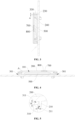
FIG. 1 is a front view of a volatilization device provided by the present application. -
FIG. 2 is a sectional view ofFIG. 1 at A-A. -
FIG. 3 is a sectional view ofFIG. 1 at B-B. -
FIG. 4 is a transverse section view of volatilization device provided by the present application. -
FIG. 5 is an enlarged view ofFIG. 4 at A. -
FIG. 6 is a first exploded view of a volatilization device provided by the present application. -
FIG. 7 is a second exploded view of a volatilization device provided by the present application. -
FIG. 8 is a third exploded view of a volatilization device provided by the present application. -
FIG. 9 is a first longitudinal exploded view of a volatilization device provided by the present application. -
FIG. 10 is a second longitudinal exploded view of a volatilization device provided by the present application. -
FIG. 11 a first perspective view of a back cover provided by the present application. -
FIG. 12 a second perspective view of a back cover provided by the present application. -
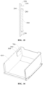
FIG. 13 is a longitudinal exploded view of a front cover provided by the present application. -
FIG. 14 is a structural diagram of a drawer (installed with a volatilization device) provided by the present application. - 100: housing; 101: accommodation cavity; 102: first buffer cavity; 103: second buffer cavity; 200: front cover; 210: baffle plate; 211: gap; 220: second annular rib; 230: first clamping hook; 240: clamping buckle; 250: third annular rib; 260: force applying member; 300: back cover; 301: air outlet; 310: first annular rib; 311: notch; 320: partition plate; 321: second vent hole; 322: first clamping hole; 330: wedge-shaped protrusion; 340: second clamping hook; 400: box body; 401: second clamping hole; 410: drawer; 500: chlorine dioxide slow-release agent; 610: first magnetic member; 620: second magnetic member; 700 transparent plate; 800: color-changing member.
- In order to more clearly illustrate the objectives, solutions, and advantages of the present application, the embodiments of the present application are further described in detail below in combination with the accompanying drawings and implementation. It should be noted, without confliction, the embodiments or the features of the embodiments can be combined with each other.
- In the description of the present application, it is to be noted that, the orientation or positional relations specified by terms such as "central", "longitudinal", "transverse", "upper", "lower", "front", "back", "left", "right", "vertical", "horizontal", "top", "bottom", "inner", "outer" and the like, are based on the orientation or positional relations shown in the drawings, which is merely for convenience of description of the present application and to simplify description, but does not indicate or imply that the stated devices or components must have the particular orientation and be constructed and operated in a particular orientation, and thus it is not to be construed as limiting the present application. Furthermore, the terms "first", "second", "third" and the like are only used for descriptive purposes and should not be construed as indicating or implying a relative importance.
- In the description of the present application, it is to be noted that unless explicitly specified and defined otherwise, the terms "connected to" and "connected" shall be understood broadly, for example, it may be either fixedly connected or detachably connected, or can be integrated; it may be either mechanically connected, or electrically connected; it may be either directly connected, or indirectly connected through an intermediate medium. The specific meanings of the terms above in the present application can be understood by a person skilled in the art in accordance with specific conditions.
- As shown in
FIG. 1 to FIG. 4 , a volatilization device of an embodiment includes ahousing 100 and a color-changingmember 800. Thehousing 100 has a cavity for accommodating an object to be stored, and thehousing 100 is provided with anair outlet 301 communicated with the cavity. The color-changingmember 800 is fixed on thehousing 100, where a side of the color-changingmember 800 is exposed to the cavity, and another side of the color-changingmember 800 visible from an outer wall of thehousing 100, that is, the color-changingmember 800 can be observed from an outer side of thehousing 100. The color-changingmember 800 changes color according to a concentration of a target gas (that is, a gas released by an object to be stored) in the cavity. The object to be stored can be, but is not limited to, a solid fungicide or a solid aromatic agent. - By taking an object to be stored being chlorine dioxide slow-
release agent 500 and a color-changingmember 800 being gelatin as an example, the working principle of the volatilization device in an embodiment of the present application when applied to a refrigerator is described as follows. - Gelatin is the product of partial hydrolysis of collagen, and is a hydrophilic colloid of macromolecules. Gelatin is colorless to light yellow solid, and odorless, tasteless and shiny. Gelatin is insoluble in water, but when soaked in water, it can absorb 5 to 10 times of the water, and then is expanded and softened. After the gelatin absorbing yellowish green to orange chlorine dioxide gas, gelatin color will become yellowish green to orange.
- When being used, the
housing 100 placed with chlorine dioxide slow-release agent 500 is put into the refrigerator, and water vapor in the refrigerator will enter the cavity through theair outlet 301. The chlorine dioxide slow-release agent 500 stored in the cavity releases chlorine dioxide gas after absorbing the water vapor. Since a side of the color-changing member 800 (that is, the gelatin) is exposed to the cavity, the gelatin can directly contact with the chlorine dioxide gas in the cavity. The color of the gelatin gradually changes from colorless to light yellow to yellowish green to orange after absorbing the chlorine dioxide gas. In addition, the chlorine dioxide gas in the cavity continuously flows into the refrigerator through theair outlet 301. With the passage of time, the ability of chlorine dioxide slow-release agent 500 to release chlorine dioxide gas gradually weakens. After the chlorine dioxide slow-release agent 500 fails, the chlorine dioxide slow-release agent 500 will not release chlorine dioxide gas. The chlorine dioxide gas adsorbed by gelatin is released, and the color of gelatin changes from yellow green to orange yellow to light yellow to colorless. Since another side of the gelatin can be seen from an outer wall of thehousing 100, the user does not need to open thehousing 100, and the color changing of the gelatin can be observed directly from the outer side of thehousing 100. When the user observes that the color of gelatin is yellowish green to orange yellow, it indicates that the chlorine dioxide slow-release agent 500 is still effective; and when the user observes that the color of the gelatin is restored to light yellow to colorless, it indicates that the chlorine dioxide slow-release agent 500 has failed, so that the user can replace the chlorine dioxide slow-release agent 500 or the entire volatilization device in time. - In order to make a side the color-changing
member 800 being exposed to the cavity and another side of the color-changingmember 800 being visible from the outer wall of thehousing 100, the installation position and modes of the color-changingmember 800 are various. The following modes will be given as examples. - Mode one: one side of the color-changing
member 800 is directly exposed to the cavity. As shown inFIG. 3, FIG. 4 ,FIG. 6 and FIG. 7 , an observation window communicated with the cavity is provided on thehousing 100, and the color-changingmember 800 is embedded in the observation window. In this mode, one side of the color-changingmember 800 is exposed to the cavity, and another side of the color-changingmember 800 is exposed to the external environment. In order to avoid the color-changingmember 800 from being damaged, the observation window is further embedded with atransparent plate 700, and thetransparent plate 700 is provided on a side of the color-changingmember 800 away from the cavity. In order to improve the accuracy, as shown inFIG. 8 and FIG. 9 , there can be provided with a plurality of observation windows. - Mode two: one side of the color-changing
member 800 is indirectly exposed to the cavity. Since theair outlet 301 is communicated with the cavity, the color-changingmember 800 can be embedded in theair outlet 301, and a projection area of the color-changingmember 800 on theair outlet 301 is smaller than an area of theair outlet 301, that is, the color-changingmember 800 does not block theair outlet 301 completely. For example, when theair outlet 301 is rectangular, the color-changingmember 800 can be a rectangular structure, which has the same width as theair outlet 301 and has a length being less than the length of theair outlet 301. For another example, when theair outlet 301 is round or oval, the color-changingmember 800 can be an annular structure. - Mode three: the color-changing
member 800 is directly exposed to the cavity as a whole. In an embodiment, thehousing 100 is made of transparent material such as transparent plastic, and the color-changingmember 800 is directly fixed on the inner wall of thehousing 100. - In the following, the object to be stored being chlorine dioxide slow-
release agent 500 is still taken as an example. Considering that the temperature in the refrigerator is much lower than the temperature of the external environment, the air with higher external temperature will condense into water vapor after entering the refrigerator during the taking and releasing of the food, which will make the chlorine dioxide slow-release agent 500 absorb too much water vapor and continuously produce a large amount of chlorine dioxide gas. This will not only greatly shorten the actual service life of the chlorine dioxide slow-release agent 500, but also affect the user experience and even corrode an inner wall of the refrigerator. In order to slow down the gas exchanging speed of the chlorine dioxide slow-release agent 500 and the outside, as shown inFIG. 2 , the cavity of thehousing 100 is provided with a firstannular rib 310, and the firstannular rib 310 divides the cavity into anaccommodation cavity 101 and an annular cavity distributed inside and outside, and theaccommodation cavity 101 is provided on an inner side of the annular cavity. The firstannular rib 310 is provided with a first vent hole communicating theaccommodation cavity 101 with the annular cavity, and the first vent hole is provided separately with theair outlet 301. Since theair outlet 301 of thehousing 100 is provided separately with the first vent hole of the firstannular rib 310, whether the external gas flows from theair outlet 301 to theaccommodation cavity 101, or the chlorine dioxide gas released by the chlorine dioxide slow-release agent 500 in theaccommodation cavity 101 flows from theaccommodation cavity 101 to theair outlet 301, the above flow paths will not be straight lines, and the gas needs to change a flow direction for a plurality of times, thereby slowing down the gas exchanging speed of the chlorine dioxide slow-release agent 500 in theaccommodation cavity 101 with the outside, and prolonging the service life of the chlorine dioxide slow-release agent 500. - From the above, it should be noted that the chlorine dioxide gas will pass through the
accommodation cavity 101, the annular cavity and theair outlet 301 during the whole process, so the color-changingmember 800 can be exposed to any one of theaccommodation cavity 101, the annular cavity and theair outlet 301. - In an embodiment, as shown in
FIG. 2 ,FIG. 11 and FIG. 12 , in order to reduce the flow speed of gas in the annular cavity, the annular cavity is provided with apartition plate 320, and thepartition plate 320 divides the annular cavity into two buffer cavities distributed in front and back. Thepartition plate 320 is provided with asecond vent hole 321 communicating two buffer cavities; theaccommodation cavity 101 is communicated with one of the two buffer cavities through the first vent hole, and another buffer cavity is communicated with theair outlet 301. - In order to facilitate description, the buffer cavity located on the front side in
FIG. 2 is named as thefirst buffer cavity 102, and the buffer cavity located on the back side is named as thesecond buffer cavity 103. It is assumed that theaccommodation cavity 101 is communicated with thefirst buffer cavity 102 through the first vent hole, and thesecond buffer cavity 103 is communicated with theair outlet 301. After thehousing 100 being put into the refrigerator, the water vapor in the refrigerator will enter thesecond buffer cavity 103 through theair outlet 301. Since thesecond buffer cavity 103 is communicated with thefirst buffer cavity 102 through thesecond vent hole 321, the water vapor entering thesecond buffer cavity 103 will flow into thefirst buffer cavity 102 through thesecond vent hole 321 from back to front, and then enter theaccommodation cavity 101 through the first vent hole. The chlorine dioxide slow-release agent 500 in theaccommodation cavity 101 will produce chlorine dioxide gas after absorbing the water vapor entering theaccommodation cavity 101. When the chlorine dioxide gas in theaccommodation cavity 101 reaches a certain amount, the chlorine dioxide gas will enter thefirst buffer cavity 102 through the first vent hole. After the chlorine dioxide gas in thefirst buffer cavity 102 accumulates to a certain amount, it will flow through thesecond vent hole 321 into thesecond buffer cavity 103 from front to back, and finally discharge from thehousing 100 through theair outlet 301 and release into the refrigerator. It should be noted that whether the water vapor in the refrigerator flows from theair outlet 301 to theaccommodation cavity 101, or the chlorine dioxide gas produced by the chlorine dioxide slow-release agent 500 flows from theaccommodation cavity 101 to theair outlet 301, the two flow paths are nonlinear, and the gas needs to change the flow direction for a plurality of times. Moreover, the speed of the gas flowing between thefirst buffer cavity 102 and thesecond buffer cavity 103 is significantly reduced by the blocking of thepartition plate 320. - It should be noted that the
cavity 101 can also be directly communicated with thesecond buffer cavity 103 through the first vent hole in addition to being directly communicated with thefirst buffer cavity 102 through the first vent hole. In this case, theair outlet 301 is communicated with thefirst buffer cavity 102. The external gas enters thefirst buffer cavity 102 through theair outlet 301, and the external gas accumulated in thefirst buffer cavity 102 flows into thesecond buffer cavity 103 from front to back through thesecond vent hole 321, and then enters theaccommodation cavity 101 through the first vent hole. Since the gas generated by the object to be stored in theaccommodation cavity 101 flows from theaccommodation cavity 101 to theair outlet 301 in the opposite way, it will not be described here. - As shown in
FIG. 4 and FIG. 5 , the first vent hole is anotch 311 formed at a first side edge of the firstannular rib 310, theair outlet 301 is provided near a second side edge of the firstannular rib 310, and the first side edge and the second side edge of the firstannular rib 310 are located opposite to each other. The advantage of this arrangement is that the front-back distance between thenotch 311 and theair outlet 301 can be maximized, thereby prolonging the flow time of the gas in the two buffer cavities. In addition, in order to further slow down the speed of gas passing through thenotch 311, the inner wall of thehousing 100 facing thenotch 311 is provided with abaffle plate 210 opposite to thenotch 311, and thebaffle plate 210 is located in theaccommodation cavity 101. A free end of thebaffle plate 210 extends towards the second side edge of the firstannular rib 310. An extension length of thebaffle plate 210 is not less than a height of thenotch 311. There is agap 211 between a side wall of thebaffle plate 210 facing the firstannular rib 310 and the firstannular rib 310. - Taking the chlorine dioxide slow-
release agent 500 as an example still, the buffer cavity on a front side inFIG. 2 is named as thefirst buffer cavity 102, and the buffer cavity on a back side is named as thesecond buffer cavity 103. Thenotch 311 is formed on a front edge of the firstannular rib 310, and thefirst buffer cavity 102 is communicated with theaccommodation cavity 101 through thenotch 311. One end of thebaffle plate 210 is fixed on a front surface of thehousing 100, and another end of thebaffle plate 210 extends backward. Theair outlet 301 is formed on the outer wall of thehousing 100 and is close to a back edge of the secondannular rib 220. Bing blocked by thebaffle plate 210, after the chlorine dioxide gas produced by the chlorine dioxide slow-release agent 500 in theaccommodation cavity 101 reaches a certain amount, the chlorine dioxide gas must first bypass thebaffle plate 210 and pass through thegap 211 between thebaffle plate 210 and the firstannular rib 310 to reach thenotch 311, and then flow into thefirst buffer cavity 102. When the chlorine dioxide gas in thefirst buffer cavity 102 accumulates to a certain amount, it will flow through thesecond vent hole 321 into thesecond buffer cavity 103 from front to back, and finally discharge from thehousing 100 through theair outlet 301. The path of the gas in the external environment to thecavity 101 through the air outlet is opposite to the above direction, and will not be described here. It should be noted that whether the gas in the external environment flows from theair outlet 301 to theaccommodation cavity 101, or the gas generated by the object to be stored in theaccommodation cavity 101 flows to theair outlet 301, the gas needs to bypass at least two bends, and needs to change the flow direction for a plurality of times, which significantly slows down the speed of gas exchange between the object to be stored in theaccommodation cavity 101 and the outside, thereby prolonging the service life of the object to be stored. - In addition, as shown in
FIG. 4 andFIG. 7 , the first side edge of the firstannular rib 310 can be provided with a plurality ofnotches 311, and in this case, thebaffle plate 210 can be an annular plate to facilitate processing. In addition, in order to preventbaffle plate 210 from affecting the storage of the object to be stored in thehousing 101, the extended length of thebaffle plate 210 is equal to or slightly greater than the height of thenotch 311. In order to better control the gas flow speed, as shown inFIG. 5 , the height h of thegap 311 can be, but not limited to, 0.3 mm ~ 1.5 mm, and the width d of thegap 211 can be, but not limited to, 0.3 mm ∼ 1 mm. - In addition, considering the
housing 100 being installed in a vertical direction generally, taking the refrigerator as an example, as shown inFIG. 14 , thehousing 100 is usually fixed on a side wall of adrawer 410 of the refrigerator. In order to prevent condensations on the food material from directly falling into theair outlet 301 of thehousing 100, based on the orientation inFIG. 3 , theair outlet 301 can be provided on a left wall, a right wall and/or a bottom surface of thehousing 100. That is, in addition to a top surface of thehousing 100, theair outlet 301 can be provided at anywhere else in thehousing 100. - As shown in
FIG. 6 , thehousing 100 includes afront cover 200 and aback cover 300. One side of theback cover 300 is an opening, thefront cover 200 is detachably covered on the opening, and a cavity is formed by being surrounded by thefront cover 200 and theback cover 300. One side edge of the firstannular rib 310 is fixed on theback cover 300, and another side edge of the firstannular rib 310 extends to thefront cover 200. Therefore, as shown inFIG. 2 , after thefront cover 200 covered on the opening of theback cover 300, and an end surface of the opening of theback cover 300 and an end surface of the firstannular rib 310 extending to thefront cover 200 close to an inner wall of thefront cover 200. Two seals can be formed among thefront cover 200 and theback cover 300, so that the external gas can be prevented from entering thecavity 101 through a seam between thefront cover 200 and theback cover 300. As shown inFIG. 6 , the firstannular rib 310 and thepartition plate 320 can be integrated with theback cover 300 in the case of apartition plate 320 being provided in the annular cavity. In order to facilitate the formation of thepartition plate 320, an opposite side of the opening on theback cover 300 has an annular opening provided relative to thepartition plate 320, that is, a side of thesecond buffer cavity 103 back to thefirst buffer cavity 102 inFIG. 2 is the opening. - It should be noted that there are many modes to realize the detachable connection between the
front cover 200 and theback cover 300. - Mode one: clamping connection. As shown in
FIG. 3 ,FIG. 7 andFIG. 13 , a side wall of the annular cavity is provided with a plurality of wedge-shaped protrusions 330 A side of the front cover facing the back cover is provided with a plurality of first clamping hooks 230 corresponding to the wedge-shapedprotrusions 330 in one-to-one correspondence. Thefirst clamping hook 230 clamps with the corresponding wedge-shapedprotrusion 330. As shown inFIG. 3 , thefirst clamping hook 230 includes a supporting arm and a hook portion. One end of the supporting arm is fixed to thefront cover 200, and a side wall of another end of the supporting arm is provided with a hook portion. The supporting arm and the hook portion can be integrally formed. As shown inFIG. 10 , in order to ensure the smooth clamping of thefirst clamping hook 230 and the wedge-shapedprotrusion 330, the range of a height D the hook portion protruding from the supporting arm can be 0.5 mm ~ 1 mm. In addition, as shown inFIG. 3 andFIG. 8 , in the case of thepartition plate 320 being provided in the annular cavity, in order to ensure that thefirst clamping hook 230 and the wedge-shapedprotrusion 330 have sufficient clamping space, the wedge-shapedprotrusion 330 can be provided on a side wall of the buffer cavity away from thefront cover 200, and then thepartition plate 320 is provided with thefirst clamping hole 322 corresponding to the wedge-shapedprotrusion 330. When the volatilization device is used, the object to be stored, such as chlorine dioxide slow-release agent 500, is first placed in theaccommodation cavity 101; a side of thefront cover 200 provided with thefirst clamping hook 230 faces the opening of theback cover 300, and thefirst clamping hook 230 passes through thefirst clamping hole 322 and is inserted into the buffer cavity provided with the wedge-shaped protrusion 330 (that is, the second buffer cavity 103); finally, it is only necessary to press thefront cover 200 backwards, the hook portion of thefirst clamping hook 230 slides to the back of the wedge-shapedprotrusion 330 along a wedge surface corresponding to the wedge-shapedprotrusion 330 driving by this pressing force, and then thefront cover 200 can be fixed to the opening of theback cover 300. - Similarly, in order to facilitate the fixation of the volatilization device, as shown in
FIG. 7 , a side of theback cover 300 back to thefront cover 200 is provided with a plurality of second clamping hooks 340. Taking therefrigerator drawer 410 as an example, as shown inFIG. 6 , the side wall of therefrigerator drawer 410 can be pre-injected into thesecond clamping hole 401 corresponding to thesecond clamping hook 340 in one-to-one correspondence, and a side wall of thesecond clamping hole 401 can also be provided with a wedge-shaped protrusion for matching with thesecond clamping hook 340. - Mode two: magnetic attraction. As shown in
FIG. 10 , thefront cover 200 is provided with a firstmagnetic member 610, and theback cover 300 is provided with a secondmagnetic member 620 engaging with the firstmagnetic member 610. It should be noted that the side of thefront cover 200 towards theback cover 300 can be provided with a plurality of firstmagnetic members 610. In this case, the annular cavity is provided with a secondmagnetic member 620 corresponding to the firstmagnetic member 610 in one-to-one correspondence. In order to ensure the airtightness between thefront cover 200 and theback cover 300, there is at least four firstmagnetic members 610. The four firstmagnetic members 610 are distributed in four corners of thefront cover 200, and the secondmagnetic member 620 is distributed in four corners of the annular cavity. The firstmagnetic member 610 can be, but not limited to, an iron sheet, and the secondmagnetic member 620 can be, but not limit to, a magnet. It should be noted that the positions of the firstmagnetic member 610 and the secondmagnetic member 620 are not limited by the attached figures, and the firstmagnetic member 610 and the secondmagnetic member 620 described here are components that can react to a magnetic field, that is, components that can be attracted or repelled by the magnetic field, such as magnets or components made of magnetic materials. - Similarly, in order to facilitate the fixation of the volatilization device, the side of the
back cover 300 back to thefront cover 200 can be fixed with a third magnetic member, and a fourth magnetic member can be fixed on the side wall of therefrigerator drawer 410. The third magnetic member is configured to engage with the fourth magnetic member. - For mode one and mode two, as shown in
FIG. 1 andFIG. 7 , in order to facilitate the removal of thefront cover 200 from theback cover 300, an edge of thefront cover 200 is formed with aforce applying member 260, and theforce applying member 260 is pushed out of theback cover 300. When thefront cover 200 needs to be removed, the user only need to hold theforce applying member 260 and pull thefront cover 200 backward, that is, in a direction away from theback cover 300. Theforce applying member 260 can be provided in a side edge of thefront cover 200, to facilitate the user to apply concentrated force on one side. As shown inFIG. 1 , the height H of theforce applying member 260 protruding out off theback cover 300 is not less than 1 mm, and the width W of theforce applying member 260 is not less than 10 mm. - Mode three: thread connection. In an embodiment, the edge of the
front cover 200 bends backwards to form a flanging. An inner wall of the flanging has internal threads, and an outer wall of theback cover 300 has external threads matching with the internal threads. When installing thefront cover 200, it is only necessary to buckle thefront cover 200 behind the opening of theback cover 300, and then screw thefront cover 200. - Mode four: screw connection. The end surface of the opening of the
back cover 300 has a plurality of threaded holes, and thefront cover 200 is provided with a through hole corresponding to the threaded holes. When installing thefront cover 200, thefront cover 200 is first provided on theback cover 300, the through hole of thefront cover 200 is aligned with the corresponding thread hole, and then a screw is screwed into the corresponding thread hole after passing through the through hole. - In addition, as shown in
FIG. 2 , in order to further prevent the external gas from entering theaccommodation cavity 101 through the seam between thefront cover 200 and theback cover 300, the side of thefront cover 200 facing theback cover 300 is provided with a secondannular rib 220, the secondannular rib 220 extends into the annular cavity, and the secondannular rib 220 closes to a side wall of theback cover 300. Therefore, even if the external gas flows into the seam between the end surfaces of thefront cover 200 and theback cover 300, since the secondannular rib 220 closes to the side wall of theback cover 300, it is blocked by the secondannular rib 220, and these external gases cannot enter the annular cavity, and then cannot enter theaccommodation cavity 101. - As shown in
FIG. 8 , theair outlet 301 is formed on the side wall of theback cover 300, and theair outlet 301 is located on an edge of theback cover 300 away from thefront cover 200, to avoid food materials put into the refrigerator from blocking theair outlet 301. The color-changingmember 800 can be fixed to thefront cover 200 and/or theair outlet 301. As shown inFIG. 6 to FIG. 8 , a left wall, a right wall and a bottom surface of theback cover 300 are provided withair outlets 301. The advantage of this arrangement is that it cannot only prevent condensations on the food materials from directly falling into theair outlet 301, but also meet the requirements of theaccommodation cavity 101 exchanging gas with the outside. - In addition, as shown in
FIG. 7 andFIG. 13 , in order to facilitate the replacement and fixation of the object to be stored, the side of thefront cover 200 facing theback cover 300 is provided with a plurality of clamping buckles 240, and a placement space for the object to be stored is formed among the plurality of the clamping buckles 240. A free end of the clampingbuckle 240 bends towards a center of thefront cover 200 to hold the object to be stored. When it is necessary to replace the object to be stored, such as the chlorine dioxide slow-release agent 500, the user can first remove thefront cover 200 from theback cover 300, and then remove the chlorine dioxide slow-release agent 500 that is previously fixed between the plurality of clamping buckles 240, and then the new chlorine dioxide slow-release agent 500 is placed between the plurality of clampingbuckle 240, and an edge of the new chlorine dioxide slow-release agent 500 is held under the free end of the clamping buckles 240, and finally thefront cover 200 and the object to be stored are installed on theback cover 300 together. During the whole replacement process, the user only needs to remove thefront cover 200 without removing the entire volatilization device. - As shown in
FIG. 13 , in order to facilitate the installation and positioning of the object to be stored, a thirdannular rib 250 is provided on the side of thefront cover 200 towards theback cover 300, and a plurality of clamping buckles 240 are fixed on the thirdannular rib 250 and provided along a circumferential direction of the thirdannular rib 250 at intervals. In addition, in order to increase the holding force applied to the object to be stored by the clampingbuckle 240, a fixed end of the clampingbuckle 240 and the thirdannular rib 250 can be rotatably connected by a rotating shaft, which is sleeved with a torsion spring. When it is necessary to place object to be stored, the user can first pull up theclamping buckle 240, that is, the clampingbuckle 240 is rotated along a direction away from the inner wall of thefront cover 200; then the object to be stored is placed in an area surrounded by the thirdannular rib 250; finally, the clampingbuckle 240 is released. The clampingbuckle 240 is driven by the torsion spring to rotate towards the inner wall of thefront cover 200 until the object to be stored are compressed. The thirdannular rib 250 and thebaffle plate 210 can be a same component. - In addition, the embodiment of the present application further provides a storage device, which includes a
box body 400 and the volatilization device mentioned above, where thehousing 100 is fixed in thebox body 400. Thebox body 400 can be, but not limited to, a refrigerator, a retail cabinet, a display cabinet or a wardrobe. For example, when thebox body 400 is a refrigerator, thehousing 100 can be fixed on an inner wall of a tank or an inner wall of a door body of the refrigerator, or on a side wall of a bottle frame or adrawer 410 of the refrigerator. - By adopting the volatilization device mentioned above, the storage device in the embodiments can not only meet the requirements of sterilization and deodorization in the
box body 400, but also can intuitively determine the effectiveness of the object to be stored by observing the color-changing member of the color-changingmember 800, to facilitate the user to change it in time. - The above embodiments are only used to illustrate the embodiments of the present application, rather than limiting them. Although the present application has been described in detail with reference to the above embodiments, those of ordinary skill in the art should understand that the various combinations, modifications or equivalent replacements of the solutions of the present application are not apart from the scope of the solutions of the present application, and should be covered in the scope of the claims of the present application.
Claims (15)
- A volatilization device, comprising:a housing, having a cavity, wherein the housing is provided with an air outlet communicated with the cavity; anda color-changing member, fixed to the housing, wherein a side of the color-changing member is exposed to the cavity, another side of the color-changing member is visible from an outer wall of the housing, and the color-changing member changes color according to a concentration of a target gas in the cavity.
- The volatilization device according to claim 1, wherein an observation window communicated with the cavity is provided on the housing, and the color-changing member is embedded in the observation window.
- The volatilization device according to claim 2, wherein a transparent plate is embedded in the observation window, and the transparent plate is provided on a side of the color-changing member away from the cavity.
- The volatilization device according to claim 1, wherein the color-changing member is embedded in the air outlet, and a projection area of the color-changing member on the air outlet is smaller than an area of the air outlet.
- The volatilization device according to claim 1, wherein the color-changing member is gelatin, and the target gas is chlorine dioxide gas.
- The volatilization device according to any one of claims 1 to 5, further comprising:
a first annular rib, provided in the cavity to divide the cavity into an accommodation cavity and an annular cavity distributed inside and outside, wherein the accommodation cavity is provided on an inner side of the annular cavity, wherein the first annular rib is provided with a first vent hole communicating the accommodation cavity with the annular cavity, and the first vent hole is provided separately with the air outlet. - The volatilization device according to claim 6, further comprising:a partition plate, provided in the annular cavity to divide the annular cavity into two buffer cavities distributed in front and back, wherein the partition plate is provided with a second vent hole communicating the two buffer cavities; andthe accommodation cavity is communicated with one of the two buffer cavities through the first vent hole, and another of the two buffer cavities is communicated with the air outlet.
- The volatilization device according to claim 6, wherein the first vent hole is a notch formed at a first side edge of the first annular rib, and the air outlet is provided near a second side edge of the first annular rib located opposite to the first side edge of the first annular rib.
- The volatilization device according to claim 8, wherein an inner wall of the housing facing the notch is provided with a baffle plate opposite to the notch, and the baffle plate is located in the accommodation cavity, a free end of the baffle plate extends toward the second side edge of the first annular rib, an extension length of the baffle plate is not less than a height of the notch, and a gap is provided between a side wall of the baffle plate facing the first annular rib and the first annular rib.
- The volatilization device according to claim 6, wherein the housing comprises:a back cover, wherein a side of the back cover is an opening; anda front cover, detachably covered at the opening to form the cavity surrounded by the front cover and the back cover, wherein one side edge of the first annular rib is fixed to the back cover, and another side edge of the first annular rib extends to the front cover.
- The volatilization device according to claim 10, wherein the air outlet is formed on a side wall of the back cover and is located at an edge of the back cover away from the front cover, and the color-changing member is fixed on the front cover and/or the air outlet.
- The volatilization device according to claim 10, wherein a side of the front cover facing the back cover is provided with a second annular rib, and the second annular rib extends into the annular cavity, and the second annular rib closes to a side wall of the back cover.
- The volatilization device according to claim 10, wherein a side wall of the annular cavity is provided with a plurality of wedge-shaped protrusions, a side of the front cover facing the back cover is provided with a plurality of first clamping hooks corresponding to the wedge-shaped protrusions in one-to-one correspondence, and each first clamping hook clamps with the corresponding wedge-shaped protrusions.
- The volatilization device according to claim 10, wherein a side of the front cover facing the back cover is provided with a plurality of clamping buckles, a placement space of an object to be stored is formed among the plurality of clamping buckles, and a free end of the clamping buckle bends toward a center of the front cover.
- A storage device, comprising a box body and a volatilization device according to any one of claims 1-14, wherein the housing is fixed in the box body.
Applications Claiming Priority (2)
| Application Number | Priority Date | Filing Date | Title |
|---|---|---|---|
| CN202011383585.1A CN114576912B (en) | 2020-11-30 | 2020-11-30 | Volatilizing device and storage device |
| PCT/CN2020/138646 WO2022110418A1 (en) | 2020-11-30 | 2020-12-23 | Volatilization device and storage device |
Publications (3)
| Publication Number | Publication Date |
|---|---|
| EP4137765A1 true EP4137765A1 (en) | 2023-02-22 |
| EP4137765A4 EP4137765A4 (en) | 2023-11-15 |
| EP4137765B1 EP4137765B1 (en) | 2025-07-02 |
Family
ID=81755276
Family Applications (1)
| Application Number | Title | Priority Date | Filing Date |
|---|---|---|---|
| EP20963306.4A Active EP4137765B1 (en) | 2020-11-30 | 2020-12-23 | Volatilization device and storage device |
Country Status (5)
| Country | Link |
|---|---|
| US (1) | US12510289B2 (en) |
| EP (1) | EP4137765B1 (en) |
| CN (1) | CN114576912B (en) |
| ES (1) | ES3040233T3 (en) |
| WO (1) | WO2022110418A1 (en) |
Families Citing this family (1)
| Publication number | Priority date | Publication date | Assignee | Title |
|---|---|---|---|---|
| CN114992977B (en) * | 2022-07-14 | 2023-04-18 | 长虹美菱股份有限公司 | Refrigerator fresh-keeping control method and device |
Family Cites Families (49)
| Publication number | Priority date | Publication date | Assignee | Title |
|---|---|---|---|---|
| US4681739A (en) | 1982-10-19 | 1987-07-21 | The Scopas Technology Co., Inc. | Use of chlorine dioxide gas as a chemosterilizing agent |
| JPH08215533A (en) * | 1994-12-16 | 1996-08-27 | Takeda Chem Ind Ltd | Deodorizing device with gas-liquid separating chamber |
| CN1176939A (en) * | 1996-07-02 | 1998-03-25 | 段建涛 | Method and device for continuous and stable releasing chlorine dioxide |
| JPH1151552A (en) * | 1997-08-06 | 1999-02-26 | Matsushita Refrig Co Ltd | Refrigerator |
| JPH11211342A (en) * | 1998-01-28 | 1999-08-06 | Matsushita Refrig Co Ltd | Vegetable chamber of refrigerator |
| JP3318276B2 (en) * | 1998-12-16 | 2002-08-26 | 松下冷機株式会社 | refrigerator |
| JP3680116B2 (en) * | 1999-07-09 | 2005-08-10 | シャープ株式会社 | refrigerator |
| JP2001314492A (en) | 2000-05-02 | 2001-11-13 | San Seal:Kk | Air conditioner provided with deodorizing and sterilizing gas supplying means |
| US7195744B2 (en) * | 2001-08-28 | 2007-03-27 | Ecolab, Inc. | Device for holding a container for a composition that produces an antimicrobially active gas |
| JP2005016875A (en) * | 2003-06-27 | 2005-01-20 | Matsushita Electric Ind Co Ltd | Storage |
| US7383946B2 (en) * | 2004-03-26 | 2008-06-10 | Hughes Kenneth D | Materials for storing and releasing reactive gases |
| US20060008919A1 (en) * | 2004-07-09 | 2006-01-12 | Boay Yoke P | Method and apparatus for detecting gas/radiation that employs color change detection mechanism |
| CN1319626C (en) * | 2005-01-11 | 2007-06-06 | 佛山市顺德区阿波罗环保器材有限公司 | Production of colouring air filter |
| US8517483B2 (en) * | 2010-02-25 | 2013-08-27 | Whirlpool Corporation | Modular system for a domestic refrigerator |
| CN101803610B (en) * | 2010-03-22 | 2012-07-18 | 北京欧凯纳斯科技有限公司 | Self regulation and control type chlorine dioxide combination and application thereof in tobacco warehouse storage |
| FR2969295B1 (en) * | 2010-12-16 | 2012-12-14 | Commissariat Energie Atomique | MULTIFUNCTIONAL DETECTOR OF GASEOUS COMPOUNDS AND APPLICATIONS THEREOF |
| CN202485308U (en) * | 2011-12-31 | 2012-10-10 | 松下电器研究开发(苏州)有限公司 | Antibacterial deodorant box for refrigerator and refrigerator |
| JP5551843B2 (en) * | 2012-02-29 | 2014-07-16 | 日油技研工業株式会社 | Peroxide detection indicator |
| CN102657890B (en) * | 2012-05-16 | 2015-01-07 | 胡昕 | Visual color-changing indication deodorant |
| DE102012014503A1 (en) * | 2012-07-20 | 2014-01-23 | Dräger Safety AG & Co. KGaA | Gas Detection System |
| CN203455285U (en) * | 2013-08-21 | 2014-02-26 | 河南新飞电器有限公司 | Dissolved gas device and bacteria removing refrigerator with same |
| CN104643254B (en) * | 2013-11-25 | 2018-10-12 | 海尔集团公司 | Anti-bacterial refreshing device and refrigerator |
| CN104664544A (en) * | 2013-11-29 | 2015-06-03 | 海尔集团公司 | Microcapsule anti-bacterial agent and refrigerator |
| CN104664545A (en) * | 2013-11-29 | 2015-06-03 | 海尔集团公司 | Antibacterial preservation component and preparation method thereof and refrigerator |
| CN203858200U (en) * | 2014-05-27 | 2014-10-01 | 苏州露水生物技术有限公司 | Ethylene oxide gas safety detection card |
| KR102257497B1 (en) * | 2014-07-21 | 2021-05-31 | 삼성전자주식회사 | Gas sensor, refrigerator having the same and control method for the refrigerator |
| CN204575542U (en) * | 2015-04-17 | 2015-08-19 | 深圳九星印刷包装集团有限公司 | Look becomes indicating device |
| CN104777162B (en) * | 2015-04-17 | 2018-02-09 | 深圳九星印刷包装集团有限公司 | Discoloration instruction device |
| CN205619677U (en) * | 2016-04-08 | 2016-10-05 | 合肥华凌股份有限公司 | Odour removal device and refrigerator disinfect |
| CN105911054A (en) * | 2016-04-21 | 2016-08-31 | 林业城 | Microbiological treatment system based on gas detection |
| US11313804B2 (en) * | 2016-09-09 | 2022-04-26 | Medtronic, Inc | Fluid sensor apparatus |
| US20180073989A1 (en) * | 2016-09-09 | 2018-03-15 | Medtronic, Inc. | Fluid sensor card |
| CN107179314B (en) * | 2016-09-28 | 2019-09-03 | 成都新睿泰康科技有限公司 | A kind of carbon dioxide gas detection composition and carbon dioxide gas indicator and its application using the composition |
| CN106860899B (en) * | 2017-01-26 | 2019-01-29 | 深圳市皓明实业有限公司 | Sterilization and disinfection device and its application method |
| CN106594900A (en) * | 2017-01-26 | 2017-04-26 | 深圳市皓明实业有限公司 | Chlorine dioxide environment treatment device and use method thereof |
| CN106969591A (en) | 2017-03-08 | 2017-07-21 | 合肥华凌股份有限公司 | The control method and control device and refrigerator of refrigerator sterilization |
| CN107782723A (en) * | 2017-09-28 | 2018-03-09 | 蒋成量 | A kind of preparation method of ClO 2 solution Concentration Testing test paper |
| CN107796162A (en) * | 2017-10-23 | 2018-03-13 | 合肥华凌股份有限公司 | A kind of dry object storage box and refrigeration plant |
| CN207763319U (en) * | 2017-12-26 | 2018-08-24 | Tcl家用电器(合肥)有限公司 | Refrigerator |
| CN208124703U (en) * | 2018-04-02 | 2018-11-20 | 合肥华凌股份有限公司 | Refrigeration equipment |
| CN108993110A (en) * | 2018-07-18 | 2018-12-14 | 南京开创者环境工程有限公司 | For removing formaldehyde, eliminating the unusual smell, the composition of dry air |
| DE102018213839A1 (en) * | 2018-08-17 | 2020-02-20 | BSH Hausgeräte GmbH | Ethylene absorber unit and household refrigerator with such a unit |
| CN209825093U (en) * | 2019-04-12 | 2019-12-24 | 合肥华凌股份有限公司 | Sterilization device and refrigeration equipment |
| CN110243811B (en) * | 2019-04-30 | 2023-05-16 | 广州超威生物科技有限公司 | Method for evaluating release rate of chlorine dioxide |
| CN110145909A (en) * | 2019-06-12 | 2019-08-20 | 扬州熊猫汽车科技服务有限公司 | A kind of vehicle-mounted fruit/vegetable fresh-keeping box |
| CN110624123A (en) * | 2019-10-26 | 2019-12-31 | 河南极速环保有限公司 | Ozone disinfection result identification device, disinfection device with same and disinfection method |
| US11340011B2 (en) * | 2019-11-05 | 2022-05-24 | Electrolux Home Products, Inc. | Refrigerator drawer with cassette filter |
| CN111480655A (en) * | 2020-04-27 | 2020-08-04 | 常州工学院 | A visible discoloration solid chlorine dioxide disinfectant for removing formaldehyde |
| CN113803948B (en) * | 2020-06-16 | 2024-08-27 | 云米互联科技(广东)有限公司 | Sterilization module for refrigerator and refrigerator |
-
2020
- 2020-11-30 CN CN202011383585.1A patent/CN114576912B/en active Active
- 2020-12-23 ES ES20963306T patent/ES3040233T3/en active Active
- 2020-12-23 US US18/003,896 patent/US12510289B2/en active Active
- 2020-12-23 WO PCT/CN2020/138646 patent/WO2022110418A1/en not_active Ceased
- 2020-12-23 EP EP20963306.4A patent/EP4137765B1/en active Active
Also Published As
| Publication number | Publication date |
|---|---|
| ES3040233T3 (en) | 2025-10-29 |
| EP4137765A4 (en) | 2023-11-15 |
| US20230280078A1 (en) | 2023-09-07 |
| CN114576912A (en) | 2022-06-03 |
| WO2022110418A1 (en) | 2022-06-02 |
| EP4137765B1 (en) | 2025-07-02 |
| US12510289B2 (en) | 2025-12-30 |
| CN114576912B (en) | 2023-05-16 |
Similar Documents
| Publication | Publication Date | Title |
|---|---|---|
| US8485454B1 (en) | Rotatable and adjustable air freshener | |
| US11009287B2 (en) | Refrigerator | |
| US12510289B2 (en) | Volatilization device and storage device | |
| JP6505033B2 (en) | Aroma deodorant container for air conditioners | |
| CN214178956U (en) | Vaporizers and Storage Units | |
| JP5688845B2 (en) | Cabinet ventilation structure | |
| CN112824796B (en) | A refrigerator | |
| JP2000180034A (en) | Refrigerator | |
| CN115182142B (en) | Lifting rib and clothes dryer | |
| CN217029364U (en) | Neck-hanging type disinfection fan | |
| JP2013200109A (en) | Ice making machine | |
| CN216346909U (en) | Fragrance subassembly and air conditioner that has it | |
| CN215113456U (en) | Air duct assembly of odor-purifying and sterilizing module, odor-purifying and sterilizing module and refrigerator | |
| CN210354424U (en) | Catering self-lifting cabinet with self-heat-preservation function | |
| CN215905068U (en) | Slow-release device and locker | |
| CN222459965U (en) | Refrigerator backboard with sterilization function and refrigerator | |
| CN115218592A (en) | A wireless power supply purifying and sterilizing module and refrigerator | |
| CN220771604U (en) | Fresh-keeping storage container and refrigerator | |
| KR200391950Y1 (en) | knob for furniture | |
| CN217031524U (en) | Air treatment device | |
| CN221556959U (en) | Fragrance device capable of switching fragrance | |
| CN217031523U (en) | Functional head and air treatment device | |
| CN218960935U (en) | Drying cabinet is stored to scope | |
| CN210326698U (en) | Intelligent liquid crystal control device of switch cabinet | |
| CN213872968U (en) | Deep ultraviolet LED light source device for killing fresh air conditioner |
Legal Events
| Date | Code | Title | Description |
|---|---|---|---|
| STAA | Information on the status of an ep patent application or granted ep patent |
Free format text: STATUS: THE INTERNATIONAL PUBLICATION HAS BEEN MADE |
|
| PUAI | Public reference made under article 153(3) epc to a published international application that has entered the european phase |
Free format text: ORIGINAL CODE: 0009012 |
|
| STAA | Information on the status of an ep patent application or granted ep patent |
Free format text: STATUS: REQUEST FOR EXAMINATION WAS MADE |
|
| 17P | Request for examination filed |
Effective date: 20221115 |
|
| AK | Designated contracting states |
Kind code of ref document: A1 Designated state(s): AL AT BE BG CH CY CZ DE DK EE ES FI FR GB GR HR HU IE IS IT LI LT LU LV MC MK MT NL NO PL PT RO RS SE SI SK SM TR |
|
| A4 | Supplementary search report drawn up and despatched |
Effective date: 20231018 |
|
| RIC1 | Information provided on ipc code assigned before grant |
Ipc: G01N 21/78 20060101ALI20231012BHEP Ipc: F25D 23/10 20060101ALI20231012BHEP Ipc: F25D 17/04 20060101AFI20231012BHEP |
|
| DAV | Request for validation of the european patent (deleted) | ||
| DAX | Request for extension of the european patent (deleted) | ||
| GRAP | Despatch of communication of intention to grant a patent |
Free format text: ORIGINAL CODE: EPIDOSNIGR1 |
|
| STAA | Information on the status of an ep patent application or granted ep patent |
Free format text: STATUS: GRANT OF PATENT IS INTENDED |
|
| INTG | Intention to grant announced |
Effective date: 20250401 |
|
| GRAS | Grant fee paid |
Free format text: ORIGINAL CODE: EPIDOSNIGR3 |
|
| GRAA | (expected) grant |
Free format text: ORIGINAL CODE: 0009210 |
|
| STAA | Information on the status of an ep patent application or granted ep patent |
Free format text: STATUS: THE PATENT HAS BEEN GRANTED |
|
| AK | Designated contracting states |
Kind code of ref document: B1 Designated state(s): AL AT BE BG CH CY CZ DE DK EE ES FI FR GB GR HR HU IE IS IT LI LT LU LV MC MK MT NL NO PL PT RO RS SE SI SK SM TR |
|
| REG | Reference to a national code |
Ref country code: GB Ref legal event code: FG4D |
|
| REG | Reference to a national code |
Ref country code: CH Ref legal event code: EP |
|
| REG | Reference to a national code |
Ref country code: DE Ref legal event code: R096 Ref document number: 602020054054 Country of ref document: DE |
|
| REG | Reference to a national code |
Ref country code: IE Ref legal event code: FG4D |
|
| REG | Reference to a national code |
Ref country code: ES Ref legal event code: FG2A Ref document number: 3040233 Country of ref document: ES Kind code of ref document: T3 Effective date: 20251029 |
|
| REG | Reference to a national code |
Ref country code: NL Ref legal event code: MP Effective date: 20250702 |
|
| PG25 | Lapsed in a contracting state [announced via postgrant information from national office to epo] |
Ref country code: PT Free format text: LAPSE BECAUSE OF FAILURE TO SUBMIT A TRANSLATION OF THE DESCRIPTION OR TO PAY THE FEE WITHIN THE PRESCRIBED TIME-LIMIT Effective date: 20251103 |
|
| PG25 | Lapsed in a contracting state [announced via postgrant information from national office to epo] |
Ref country code: NL Free format text: LAPSE BECAUSE OF FAILURE TO SUBMIT A TRANSLATION OF THE DESCRIPTION OR TO PAY THE FEE WITHIN THE PRESCRIBED TIME-LIMIT Effective date: 20250702 |
|
| REG | Reference to a national code |
Ref country code: AT Ref legal event code: MK05 Ref document number: 1809628 Country of ref document: AT Kind code of ref document: T Effective date: 20250702 |
|
| PG25 | Lapsed in a contracting state [announced via postgrant information from national office to epo] |
Ref country code: IS Free format text: LAPSE BECAUSE OF FAILURE TO SUBMIT A TRANSLATION OF THE DESCRIPTION OR TO PAY THE FEE WITHIN THE PRESCRIBED TIME-LIMIT Effective date: 20251102 |
|
| PGFP | Annual fee paid to national office [announced via postgrant information from national office to epo] |
Ref country code: DE Payment date: 20251212 Year of fee payment: 6 |
|
| PG25 | Lapsed in a contracting state [announced via postgrant information from national office to epo] |
Ref country code: NO Free format text: LAPSE BECAUSE OF FAILURE TO SUBMIT A TRANSLATION OF THE DESCRIPTION OR TO PAY THE FEE WITHIN THE PRESCRIBED TIME-LIMIT Effective date: 20251002 |
|
| REG | Reference to a national code |
Ref country code: LT Ref legal event code: MG9D |
|
| PG25 | Lapsed in a contracting state [announced via postgrant information from national office to epo] |
Ref country code: AT Free format text: LAPSE BECAUSE OF FAILURE TO SUBMIT A TRANSLATION OF THE DESCRIPTION OR TO PAY THE FEE WITHIN THE PRESCRIBED TIME-LIMIT Effective date: 20250702 |
|
| PG25 | Lapsed in a contracting state [announced via postgrant information from national office to epo] |
Ref country code: FI Free format text: LAPSE BECAUSE OF FAILURE TO SUBMIT A TRANSLATION OF THE DESCRIPTION OR TO PAY THE FEE WITHIN THE PRESCRIBED TIME-LIMIT Effective date: 20250702 |
|
| PGFP | Annual fee paid to national office [announced via postgrant information from national office to epo] |
Ref country code: IT Payment date: 20251212 Year of fee payment: 6 |
|
| PG25 | Lapsed in a contracting state [announced via postgrant information from national office to epo] |
Ref country code: HR Free format text: LAPSE BECAUSE OF FAILURE TO SUBMIT A TRANSLATION OF THE DESCRIPTION OR TO PAY THE FEE WITHIN THE PRESCRIBED TIME-LIMIT Effective date: 20250702 |
|
| PG25 | Lapsed in a contracting state [announced via postgrant information from national office to epo] |
Ref country code: GR Free format text: LAPSE BECAUSE OF FAILURE TO SUBMIT A TRANSLATION OF THE DESCRIPTION OR TO PAY THE FEE WITHIN THE PRESCRIBED TIME-LIMIT Effective date: 20251003 |
|
| PG25 | Lapsed in a contracting state [announced via postgrant information from national office to epo] |
Ref country code: SE Free format text: LAPSE BECAUSE OF FAILURE TO SUBMIT A TRANSLATION OF THE DESCRIPTION OR TO PAY THE FEE WITHIN THE PRESCRIBED TIME-LIMIT Effective date: 20250702 Ref country code: CZ Free format text: LAPSE BECAUSE OF FAILURE TO SUBMIT A TRANSLATION OF THE DESCRIPTION OR TO PAY THE FEE WITHIN THE PRESCRIBED TIME-LIMIT Effective date: 20250702 |
|
| PG25 | Lapsed in a contracting state [announced via postgrant information from national office to epo] |
Ref country code: LV Free format text: LAPSE BECAUSE OF FAILURE TO SUBMIT A TRANSLATION OF THE DESCRIPTION OR TO PAY THE FEE WITHIN THE PRESCRIBED TIME-LIMIT Effective date: 20250702 |
|
| PG25 | Lapsed in a contracting state [announced via postgrant information from national office to epo] |
Ref country code: PL Free format text: LAPSE BECAUSE OF FAILURE TO SUBMIT A TRANSLATION OF THE DESCRIPTION OR TO PAY THE FEE WITHIN THE PRESCRIBED TIME-LIMIT Effective date: 20250702 Ref country code: BG Free format text: LAPSE BECAUSE OF FAILURE TO SUBMIT A TRANSLATION OF THE DESCRIPTION OR TO PAY THE FEE WITHIN THE PRESCRIBED TIME-LIMIT Effective date: 20250702 |
|
| PG25 | Lapsed in a contracting state [announced via postgrant information from national office to epo] |
Ref country code: RS Free format text: LAPSE BECAUSE OF FAILURE TO SUBMIT A TRANSLATION OF THE DESCRIPTION OR TO PAY THE FEE WITHIN THE PRESCRIBED TIME-LIMIT Effective date: 20251002 |
|
| PG25 | Lapsed in a contracting state [announced via postgrant information from national office to epo] |
Ref country code: RO Free format text: LAPSE BECAUSE OF FAILURE TO SUBMIT A TRANSLATION OF THE DESCRIPTION OR TO PAY THE FEE WITHIN THE PRESCRIBED TIME-LIMIT Effective date: 20250702 |
|
| PG25 | Lapsed in a contracting state [announced via postgrant information from national office to epo] |
Ref country code: SM Free format text: LAPSE BECAUSE OF FAILURE TO SUBMIT A TRANSLATION OF THE DESCRIPTION OR TO PAY THE FEE WITHIN THE PRESCRIBED TIME-LIMIT Effective date: 20250702 |
|
| PGFP | Annual fee paid to national office [announced via postgrant information from national office to epo] |
Ref country code: ES Payment date: 20260105 Year of fee payment: 6 |
|
| PG25 | Lapsed in a contracting state [announced via postgrant information from national office to epo] |
Ref country code: DK Free format text: LAPSE BECAUSE OF FAILURE TO SUBMIT A TRANSLATION OF THE DESCRIPTION OR TO PAY THE FEE WITHIN THE PRESCRIBED TIME-LIMIT Effective date: 20250702 |
|
| PG25 | Lapsed in a contracting state [announced via postgrant information from national office to epo] |
Ref country code: EE Free format text: LAPSE BECAUSE OF FAILURE TO SUBMIT A TRANSLATION OF THE DESCRIPTION OR TO PAY THE FEE WITHIN THE PRESCRIBED TIME-LIMIT Effective date: 20250702 Ref country code: SK Free format text: LAPSE BECAUSE OF FAILURE TO SUBMIT A TRANSLATION OF THE DESCRIPTION OR TO PAY THE FEE WITHIN THE PRESCRIBED TIME-LIMIT Effective date: 20250702 |
|
| PLBE | No opposition filed within time limit |
Free format text: ORIGINAL CODE: 0009261 |
|
| STAA | Information on the status of an ep patent application or granted ep patent |
Free format text: STATUS: NO OPPOSITION FILED WITHIN TIME LIMIT |