EP4137727B1 - Valve actuator - Google Patents
Valve actuator Download PDFInfo
- Publication number
- EP4137727B1 EP4137727B1 EP21218051.7A EP21218051A EP4137727B1 EP 4137727 B1 EP4137727 B1 EP 4137727B1 EP 21218051 A EP21218051 A EP 21218051A EP 4137727 B1 EP4137727 B1 EP 4137727B1
- Authority
- EP
- European Patent Office
- Prior art keywords
- gear
- magnet
- motor
- valve actuator
- disposed
- Prior art date
- Legal status (The legal status is an assumption and is not a legal conclusion. Google has not performed a legal analysis and makes no representation as to the accuracy of the status listed.)
- Active
Links
Images







Classifications
-
- F—MECHANICAL ENGINEERING; LIGHTING; HEATING; WEAPONS; BLASTING
- F16—ENGINEERING ELEMENTS AND UNITS; GENERAL MEASURES FOR PRODUCING AND MAINTAINING EFFECTIVE FUNCTIONING OF MACHINES OR INSTALLATIONS; THERMAL INSULATION IN GENERAL
- F16K—VALVES; TAPS; COCKS; ACTUATING-FLOATS; DEVICES FOR VENTING OR AERATING
- F16K27/00—Construction of housing; Use of materials therefor
- F16K27/02—Construction of housing; Use of materials therefor of lift valves
- F16K27/029—Electromagnetically actuated valves
-
- F—MECHANICAL ENGINEERING; LIGHTING; HEATING; WEAPONS; BLASTING
- F16—ENGINEERING ELEMENTS AND UNITS; GENERAL MEASURES FOR PRODUCING AND MAINTAINING EFFECTIVE FUNCTIONING OF MACHINES OR INSTALLATIONS; THERMAL INSULATION IN GENERAL
- F16H—GEARING
- F16H35/00—Gearings or mechanisms with other special functional features
- F16H35/10—Arrangements or devices for absorbing overload or preventing damage by overload
-
- F—MECHANICAL ENGINEERING; LIGHTING; HEATING; WEAPONS; BLASTING
- F16—ENGINEERING ELEMENTS AND UNITS; GENERAL MEASURES FOR PRODUCING AND MAINTAINING EFFECTIVE FUNCTIONING OF MACHINES OR INSTALLATIONS; THERMAL INSULATION IN GENERAL
- F16K—VALVES; TAPS; COCKS; ACTUATING-FLOATS; DEVICES FOR VENTING OR AERATING
- F16K5/00—Plug valves; Taps or cocks comprising only cut-off apparatus having at least one of the sealing faces shaped as a more or less complete surface of a solid of revolution, the opening and closing movement being predominantly rotary
- F16K5/06—Plug valves; Taps or cocks comprising only cut-off apparatus having at least one of the sealing faces shaped as a more or less complete surface of a solid of revolution, the opening and closing movement being predominantly rotary with plugs having spherical surfaces; Packings therefor
- F16K5/0647—Spindles or actuating means
-
- F—MECHANICAL ENGINEERING; LIGHTING; HEATING; WEAPONS; BLASTING
- F16—ENGINEERING ELEMENTS AND UNITS; GENERAL MEASURES FOR PRODUCING AND MAINTAINING EFFECTIVE FUNCTIONING OF MACHINES OR INSTALLATIONS; THERMAL INSULATION IN GENERAL
- F16K—VALVES; TAPS; COCKS; ACTUATING-FLOATS; DEVICES FOR VENTING OR AERATING
- F16K31/00—Actuating devices; Operating means; Releasing devices
- F16K31/02—Actuating devices; Operating means; Releasing devices electric; magnetic
- F16K31/04—Actuating devices; Operating means; Releasing devices electric; magnetic using a motor
-
- F—MECHANICAL ENGINEERING; LIGHTING; HEATING; WEAPONS; BLASTING
- F16—ENGINEERING ELEMENTS AND UNITS; GENERAL MEASURES FOR PRODUCING AND MAINTAINING EFFECTIVE FUNCTIONING OF MACHINES OR INSTALLATIONS; THERMAL INSULATION IN GENERAL
- F16K—VALVES; TAPS; COCKS; ACTUATING-FLOATS; DEVICES FOR VENTING OR AERATING
- F16K31/00—Actuating devices; Operating means; Releasing devices
- F16K31/02—Actuating devices; Operating means; Releasing devices electric; magnetic
- F16K31/04—Actuating devices; Operating means; Releasing devices electric; magnetic using a motor
- F16K31/047—Actuating devices; Operating means; Releasing devices electric; magnetic using a motor characterised by mechanical means between the motor and the valve, e.g. lost motion means reducing backlash, clutches, brakes or return means
-
- F—MECHANICAL ENGINEERING; LIGHTING; HEATING; WEAPONS; BLASTING
- F16—ENGINEERING ELEMENTS AND UNITS; GENERAL MEASURES FOR PRODUCING AND MAINTAINING EFFECTIVE FUNCTIONING OF MACHINES OR INSTALLATIONS; THERMAL INSULATION IN GENERAL
- F16K—VALVES; TAPS; COCKS; ACTUATING-FLOATS; DEVICES FOR VENTING OR AERATING
- F16K31/00—Actuating devices; Operating means; Releasing devices
- F16K31/02—Actuating devices; Operating means; Releasing devices electric; magnetic
- F16K31/06—Actuating devices; Operating means; Releasing devices electric; magnetic using a magnet, e.g. diaphragm valves, cutting off by means of a liquid
-
- F—MECHANICAL ENGINEERING; LIGHTING; HEATING; WEAPONS; BLASTING
- F16—ENGINEERING ELEMENTS AND UNITS; GENERAL MEASURES FOR PRODUCING AND MAINTAINING EFFECTIVE FUNCTIONING OF MACHINES OR INSTALLATIONS; THERMAL INSULATION IN GENERAL
- F16K—VALVES; TAPS; COCKS; ACTUATING-FLOATS; DEVICES FOR VENTING OR AERATING
- F16K31/00—Actuating devices; Operating means; Releasing devices
- F16K31/02—Actuating devices; Operating means; Releasing devices electric; magnetic
- F16K31/06—Actuating devices; Operating means; Releasing devices electric; magnetic using a magnet, e.g. diaphragm valves, cutting off by means of a liquid
- F16K31/08—Actuating devices; Operating means; Releasing devices electric; magnetic using a magnet, e.g. diaphragm valves, cutting off by means of a liquid using a permanent magnet
- F16K31/084—Actuating devices; Operating means; Releasing devices electric; magnetic using a magnet, e.g. diaphragm valves, cutting off by means of a liquid using a permanent magnet the magnet being used only as a holding element to maintain the valve in a specific position, e.g. check valves
-
- F—MECHANICAL ENGINEERING; LIGHTING; HEATING; WEAPONS; BLASTING
- F16—ENGINEERING ELEMENTS AND UNITS; GENERAL MEASURES FOR PRODUCING AND MAINTAINING EFFECTIVE FUNCTIONING OF MACHINES OR INSTALLATIONS; THERMAL INSULATION IN GENERAL
- F16K—VALVES; TAPS; COCKS; ACTUATING-FLOATS; DEVICES FOR VENTING OR AERATING
- F16K31/00—Actuating devices; Operating means; Releasing devices
- F16K31/44—Mechanical actuating means
- F16K31/52—Mechanical actuating means with crank, eccentric, or cam
- F16K31/524—Mechanical actuating means with crank, eccentric, or cam with a cam
- F16K31/52408—Mechanical actuating means with crank, eccentric, or cam with a cam comprising a lift valve
- F16K31/52425—Mechanical actuating means with crank, eccentric, or cam with a cam comprising a lift valve with a ball-shaped valve member
-
- F—MECHANICAL ENGINEERING; LIGHTING; HEATING; WEAPONS; BLASTING
- F16—ENGINEERING ELEMENTS AND UNITS; GENERAL MEASURES FOR PRODUCING AND MAINTAINING EFFECTIVE FUNCTIONING OF MACHINES OR INSTALLATIONS; THERMAL INSULATION IN GENERAL
- F16K—VALVES; TAPS; COCKS; ACTUATING-FLOATS; DEVICES FOR VENTING OR AERATING
- F16K31/00—Actuating devices; Operating means; Releasing devices
- F16K31/44—Mechanical actuating means
- F16K31/53—Mechanical actuating means with toothed gearing
-
- F—MECHANICAL ENGINEERING; LIGHTING; HEATING; WEAPONS; BLASTING
- F16—ENGINEERING ELEMENTS AND UNITS; GENERAL MEASURES FOR PRODUCING AND MAINTAINING EFFECTIVE FUNCTIONING OF MACHINES OR INSTALLATIONS; THERMAL INSULATION IN GENERAL
- F16K—VALVES; TAPS; COCKS; ACTUATING-FLOATS; DEVICES FOR VENTING OR AERATING
- F16K31/00—Actuating devices; Operating means; Releasing devices
- F16K31/44—Mechanical actuating means
- F16K31/53—Mechanical actuating means with toothed gearing
- F16K31/535—Mechanical actuating means with toothed gearing for rotating valves
-
- F—MECHANICAL ENGINEERING; LIGHTING; HEATING; WEAPONS; BLASTING
- F16—ENGINEERING ELEMENTS AND UNITS; GENERAL MEASURES FOR PRODUCING AND MAINTAINING EFFECTIVE FUNCTIONING OF MACHINES OR INSTALLATIONS; THERMAL INSULATION IN GENERAL
- F16K—VALVES; TAPS; COCKS; ACTUATING-FLOATS; DEVICES FOR VENTING OR AERATING
- F16K5/00—Plug valves; Taps or cocks comprising only cut-off apparatus having at least one of the sealing faces shaped as a more or less complete surface of a solid of revolution, the opening and closing movement being predominantly rotary
- F16K5/08—Details
- F16K5/22—Features relating to lubrication
- F16K5/227—Features relating to lubrication for plugs with spherical surfaces
-
- H—ELECTRICITY
- H02—GENERATION; CONVERSION OR DISTRIBUTION OF ELECTRIC POWER
- H02K—DYNAMO-ELECTRIC MACHINES
- H02K49/00—Dynamo-electric clutches; Dynamo-electric brakes
- H02K49/10—Dynamo-electric clutches; Dynamo-electric brakes of the permanent-magnet type
- H02K49/104—Magnetic couplings consisting of only two coaxial rotary elements, i.e. the driving element and the driven element
- H02K49/106—Magnetic couplings consisting of only two coaxial rotary elements, i.e. the driving element and the driven element with a radial air gap
-
- F—MECHANICAL ENGINEERING; LIGHTING; HEATING; WEAPONS; BLASTING
- F16—ENGINEERING ELEMENTS AND UNITS; GENERAL MEASURES FOR PRODUCING AND MAINTAINING EFFECTIVE FUNCTIONING OF MACHINES OR INSTALLATIONS; THERMAL INSULATION IN GENERAL
- F16H—GEARING
- F16H19/00—Gearings comprising essentially only toothed gears or friction members and not capable of conveying indefinitely-continuing rotary motion
- F16H19/001—Gearings comprising essentially only toothed gears or friction members and not capable of conveying indefinitely-continuing rotary motion for conveying reciprocating or limited rotary motion
-
- F—MECHANICAL ENGINEERING; LIGHTING; HEATING; WEAPONS; BLASTING
- F16—ENGINEERING ELEMENTS AND UNITS; GENERAL MEASURES FOR PRODUCING AND MAINTAINING EFFECTIVE FUNCTIONING OF MACHINES OR INSTALLATIONS; THERMAL INSULATION IN GENERAL
- F16H—GEARING
- F16H37/00—Combinations of mechanical gearings, not provided for in groups F16H1/00 - F16H35/00
- F16H37/02—Combinations of mechanical gearings, not provided for in groups F16H1/00 - F16H35/00 comprising essentially only toothed or friction gearings
- F16H37/04—Combinations of toothed gearings only
Definitions
- the disclosure relates to a valve actuator. More particularly, the disclosure relates to a valve actuator for opening and closing a ball valve.
- a ball valve is an opening/closing means that is widely used to supply or cut off the supply of a working fluid to a required place through a pipe coupled to two opposite sides of the main body of the valve by opening and closing the pipe by automatically rotating a ball thereinside by way of a motor.
- a conventional ball valve actuator connects the shaft of the gear motor with the output shaft of the ball valve through a cam and uses a sensor or step motor to turn the output shaft by an intended angle.
- a physical stopper is used to limit the rotation angle of the output shaft.
- Korean Patent No. 0392198 discloses controlling to stop the rotation of the motor, with the gear in contact with the stopper, through a limiter switch.
- Patent Document 1 Korean Patent No. 10-0392198B1 registered on July 22, 2003 .
- DE 11 2015 003071 T5 discloses a double offset valve in which a rotation shaft is eccentrically disposed from a center of a valve hole of a valve seat, and a sealing surface of the valve element is eccentrically disposed from the rotation shaft.
- US 2010/170763 A1 discloses a transmission device with overload protection.
- US 4 808 869 A discloses a motor with an integral magnetic torque limiting coupling.
- DE 11 2018 004762 T5 discloses a double eccentric valve including a valve element provided with a rotatable shaft eccentrically disposed from a center of a valve opening of a valve seat.
- KR 101 611 977 B1 discloses an actuator with an impact absorbing-type stopper.
- GB 2 340 209 A discloses a torque limited motor operated valve.
- An object of the disclosure is to provide a valve actuator capable of preventing damage to a gear when torque is applied from a motor with the gear in contact with a stopper.
- Another object of the disclosure is to provide a valve actuator capable of damping the torque of a motor applied due to over-output.
- Another object of the disclosure is to provide a valve actuator capable of reducing manufacturing costs.
- Another object is to provide a valve actuator capable of operating even under a high-speed slip condition, e.g., at thousands of rpm.
- Another object of the disclosure is to provide a valve actuator capable of lubricating a component to prevent damage to the component under a high-speed slip condition.
- a valve actuator comprises a housing, a motor disposed on the housing, a drive gear coupled to a motor shaft of the motor, a transfer gear engaging with the drive gear and rotating according to a predetermined gear ratio when the drive gear rotates, an output gear coupled to an output shaft and engaging with the transfer gear, and a stopper disposed in the housing and limiting a rotation of the output gear.
- the transfer gear comprises an outer part, an inner part disposed in the outer part, a first magnet disposed on the outer part, and a second magnet disposed on the inner part and facing the first magnet.
- the first magnet and the second magnet may have different polarities.
- An attractive force between the first magnet and the second magnet may be larger than an average output force of the motor and smaller than a maximum output force of the motor.
- the first magnet may comprise a plurality of first magnet units having different polarities between adjacent magnet units
- the second magnet may comprise a plurality of second magnet units having different polarities between adjacent magnet units and individually facing the plurality of first magnet units.
- the motor may be a DC motor.
- DC motors since it may be applied to DC motors that are inexpensive as compared with AC motors, it is possible to reduce the manufacturing costs of the product.
- An upper end and lower end of the inner part are supported by an inner surface of the housing.
- An upper or lower end of the outer part is vertically supported by the inner part.
- a height of the first magnet is larger than a height of the second magnet.
- a vertical center of the first magnet When the upper end of the outer part is vertically supported by the inner part, a vertical center of the first magnet may be disposed above a vertical center of the second magnet, and when the lower end of the outer part is vertically supported by the inner part, the vertical center of the first magnet may be disposed below the vertical center of the second magnet.
- the inner part may comprise a groove formed in a region supporting the upper end or lower end of the outer part.
- a lubricant may be disposed in the groove. The lubricant may perform lubrication to prevent damage to the components under the high-speed slip condition.
- the transfer gear may comprise a first gear engaging with the drive gear, a second gear engaging with the first gear, and a third gear engaging with the second gear.
- the first gear may comprise the outer part, the inner part, the first magnet, and the second magnet.
- a valve actuator may comprise a housing, a motor disposed on the housing, a drive gear coupled to a motor shaft of the motor, an output gear coupled to an output shaft and engaging with the drive gear, and a stopper disposed in the housing and limiting a rotation radius of the output gear.
- the drive gear may comprise an outer part, an inner part disposed in the outer part, a first magnet disposed on the outer part, and a second magnet disposed on the inner part and facing the first magnet.
- gear shaft idles due to the first magnet and the second magnet during over-output of the motor, it is possible to damp the torque of the motor applied due to over-output and hence prevent damage to the drive gear and output gear.
- the inner part may be coupled to a motor shaft and rotate along with the motor shaft.
- An upper or lower end of the outer part is vertically supported by the inner part.
- a height of the first magnet may be larger than a height of the second magnet.
- a vertical center of the first magnet When the upper end of the outer part is vertically supported by the inner part, a vertical center of the first magnet may be disposed above a vertical center of the second magnet, and when the lower end of the outer part is vertically supported by the inner part, the vertical center of the first magnet may be disposed below the vertical center of the second magnet.
- the inner part may comprise a groove formed in an area supporting the upper end or lower end of the outer part.
- a lubricant may be disposed in the groove. The lubricant may perform lubrication to prevent damage to the components under the high-speed slip condition.
- a valve actuator may comprise a housing, a motor disposed on the housing, a drive gear coupled to a motor shaft of the motor, a transfer gear engaging with the drive gear and rotating according to a first gear ratio when the drive gear rotates, an output gear coupled to an output shaft and engaging with the transfer gear, and a stopper disposed in the housing and limiting a rotation radius of the output gear.
- the transfer gear may comprise a first transfer gear, a second transfer gear rotating according to a second gear ratio when the first transfer gear rotates, a cylindrical first magnet disposed on the first transfer gear, and a cylindrical second magnet disposed on the second transfer gear.
- the first magnet and the second magnet may horizontally overlap each other, with a predetermined gap formed therebetween.
- gear shaft idles due to the first magnet and the second magnet during over-output of the motor, it is possible to damp the torque of the motor applied due to over-output and hence prevent damage to the drive gear, transfer gear, and output gear.
- a valve actuator may comprise a housing, a motor disposed on the housing, a drive gear coupled to a motor shaft of the motor, a cylindrical first magnet coupled to the drive gear, an output gear coupled to an output shaft, a cylindrical second magnet coupled to the output gear, and a stopper disposed in the housing and limiting a rotation radius of the output gear.
- the first magnet and the second magnet horizontally overlap each other, with a predetermined gap formed therebetween.
- gear shaft idles due to the first magnet and the second magnet during over-output of the motor, it is possible to damp the torque of the motor applied due to over-output and hence prevent damage to the drive gear and output gear.
- the first magnet may comprise a plurality of first magnet units circumferentially arranged
- the second magnet may comprise a plurality of second magnet units circumferentially arranged.
- the plurality of first magnet units may be magnetized to have different poles from neighboring magnet units
- the plurality of second magnet units may be magnetized to have different poles from neighboring magnet units.
- the first magnet unit and the second magnet unit facing each other, among the plurality of first magnet units and the plurality of second magnet units, may have different polarities.
- the ratio of the number of the plurality of first magnet units to the number of the plurality of second magnet units may be identical to the second gear ratio.
- valve actuator capable of preventing damage to a gear when torque is applied from a motor with the gear in contact with a stopper.
- valve actuator capable of damping the torque of a motor applied due to over-output.
- valve actuator capable of reducing manufacturing costs.
- valve actuator capable of operating even under a high-speed slip condition, e.g., at thousands of rpm.
- valve actuator capable of lubricating a component to prevent damage to the component under a high-speed slip condition.
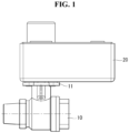
- FIG. 1 is a front view illustrating a ball valve and a valve actuator according to a first embodiment of the disclosure.
- FIG. 2 is a perspective view illustrating a valve actuator according to the first embodiment of the disclosure.
- FIG. 3 is an exploded perspective view illustrating a valve actuator according to the first embodiment of the disclosure.
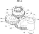
- FIGS. 4 and 5 are perspective views illustrating some components of a valve actuator according to the first embodiment of the disclosure.
- FIG. 6 is a perspective view illustrating a first gear according to the first embodiment of the disclosure.
- FIG. 7 is a plan view illustrating a first gear according to the first embodiment of the disclosure.
- FIG. 8 is a cross-sectional view illustrating a valve actuator according to the first embodiment of the disclosure.
- FIG. 9 is an enlarged view illustrating some components of FIG. 8 .
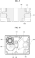
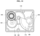
- FIGS. 10 , 11 , and 12 are views illustrating the operation of a valve actuator according to the first embodiment of the disclosure.
- FIG. 13 is an exploded perspective view illustrating
- a valve actuator 20 may include a housing 110, a motor 120, a drive gear 130, transfer gears 140, 150, and 160, an output gear 170, an output shaft 180, a stopper 190, and a magnet 200.
- the valve actuator 20 may omit some of the components or add more components.
- the valve actuator 20 may be coupled to an upper portion of a plate 11 coupled to an upper portion of a ball valve 10.
- the output shaft 180 of the actuator 20 may be coupled to a stem 13 of the ball valve 10. As the output shaft 180 of the actuator 20 rotates, the stem 13 may rotate, and a ball 16 of the ball valve 10 may rotate, opening or closing the ball valve 10.
- the ball valve 10 may include a stem fixing part 15 for coupling the stem 13 and an O-ring 14 disposed under the stem 13.
- the housing 110 may be formed in a hexahedral shape.
- the housing 110 may form the exterior of the valve actuator 20.
- the housing 110 may be disposed on one side of the ball valve 10.
- the housing 110 may be disposed on the ball valve 10.
- the motor 120, the drive gear 130, the transfer gears 140, 150, and 160, the output gear 170, the output shaft 180, and the stopper 190 may be disposed.
- the motor 120 may be disposed on the housing 110.
- the motor 120 may be coupled to a recess of the housing 110 so that one side thereof may be disposed in the housing 110, and the other side may protrude to the outside of the housing 110. This may enhance space efficiency.
- the drive gear 130 may be coupled to a motor shaft of the motor 120.
- the motor 120 may a direct current (DC) motor.
- the motor 120 may be an alternating current (AC) motor.
- AC alternating current
- the manufacturing costs of the valve actuator 20 may be reduced as compared with when the motor 120 is an AC motor.
- a DC motor may present poor rpm control accuracy as compared with an AC motor, and this may be supplemented by the physical stopper 190 of the valve actuator.
- the drive gear 130 may be coupled to the motor shaft of the motor 120. When the motor shaft of the motor 120 rotates in a first direction, the drive gear 130 may rotate in the first direction and, when the motor shaft rotates in a second direction, the drive gear 130 may rotate in the second direction.
- the drive gear 130 may engage with the transfer gears 140, 150, and 160.
- the drive gear 130 may be an external gear.
- the transfer gears 140, 150, and 160 may engage with the drive gear 130.
- the transfer gears 140, 150, and 160 may rotate according to a predetermined gear ratio when the drive gear 130 rotates.
- the transfer gears 140, 150, and 160 may engage with the output gear 170.
- the transfer gears 140, 150, and 160 may reduce the speed of the drive gear 130 at a predetermined gear ratio and transfer it to the output gear 170.
- the transfer gears 140, 150, and 160 may increase the torque transferred from the drive gear 130 and transfer it to the output gear 170.
- the transfer gears 140, 150, and 160 may include a first gear 140, a second gear 150, and a third gear 160.
- the first gear 140 may engage with the drive gear 130.
- the first gear 140 may engage with the second gear 150.
- the first gear 140 may engage with the drive gear 130 and may rotate at a predetermined gear ratio with respect to the drive gear 130.
- the first gear 140 may engage with the second gear 150 to rotate the second gear 150 at a predetermined gear ratio with respect to the first gear 140.
- the first gear 140 may include an outer part 141, a first external gear 142, an inner part 143, a second external gear 144, and magnets 200.
- the outer part 141 may be disposed outside the inner part 143.
- the outer part 141 may be radially spaced apart from the inner part 143.
- the first external gear 142 may be formed on the outer part 141.
- the first magnet 210 may be disposed on the outer part 141.
- the first external gear 142 may engage with the drive gear 130.
- the outer part 141 of the first gear 140 may rotate at a predetermined gear ratio with respect to the drive gear 130.
- the magnets 200 may include a first magnet 210 disposed on the outer part 141 and a second magnet 220 disposed on the inner part 143.
- the first magnet 210 may be radially spaced apart from the second magnet 220.
- a predetermined gap g1 may be formed between the inner surface of the first magnet 210 and the outer surface of the second magnet 220.
- the second magnet 220 may be disposed in the first magnet 210.
- the first magnet 210 and the second magnet 220 may have different polarities.
- the respective areas of the first magnet 210 and the second magnet 220, which face each other, may have different polarities. For example, if a first area of the first magnet 210 has an N pole, a first area of the second magnet 220 facing the first area of the first magnet 210 may have an S pole.
- the first magnet 210 may rotate according to the rotation of the outer part 141, and the second magnet 220 may rotate along with the first magnet 210 by magnetic force.
- the outer part 141 idles with respect to the inner part 143 due to the first magnet 210 and the second magnet 220, preventing damage to the drive gear 130, the transfer gears 140, 150, and 160, and the output gear 170.
- the attractive force between the first magnet 210 and the second magnet 220 may be larger than the average output of the motor 120 and smaller than the maximum output of the motor 120.
- the outer part 141 idles with respect to the inner part 143 due to the first magnet 210 and the second magnet 220, damping the torque of the motor 120 applied due to the over-output and hence preventing damage to the drive gear 130, the transfer gears 140, 150, and 160, and the output gear 170. In particular, this may compensate for the over-output of the motor 120 that may occur if the motor 120 is formed of a low-cost DC motor.
- the first magnet 210 may include a plurality of first magnet units 212, 214, 216, and 218 having polarities different from those of adjacent magnet units.
- the second magnet 220 may include a plurality of second magnet units 222, 224, 226, and 228 having different polarities from those of adj acent magnet units and facing the plurality of first magnet units 212, 214, 216, and 218, respectively.
- a 1-1th magnet unit 212 may have an N pole
- a 1-2th magnet unit 214 may have an S pole
- a 1-3th magnet unit 216 may have an N pole
- a 1-4th magnet unit 218 may have an S pole.
- a 2-1th magnet unit 222 may have an S pole
- a 2-2th magnet unit 224 may have an N pole
- a 2-3th magnet unit 226 may have an S pole
- a 2-4th magnet unit 228 may have an N pole.
- the number of the plurality of first magnet units 212, 214, 216, and 218 and the number of the plurality of second magnet units 222, 224, 226, and 228 each are four.
- the number of first magnet units and the number of second magnet units each may be two.
- the inner part 143 may be disposed in the outer part 141.
- the inner part 143 may be radially spaced apart from the outer part 141.
- the second external gear 144 may be formed on the inner part 143.
- the second magnet 220 may be disposed on the outer part 143.
- the outer part 143 may rotate according to the rotation of the second magnet 220.
- An upper end and lower end of the inner part 143 are supported by the inner surface of the housing 110, and an upper or lower end of the outer part 131 is vertically supported by the inner part 143.
- the height of the first magnet 210 is larger than the height of the second magnet 220.
- a vertical center of the first magnet 210 may be disposed below a vertical center of the second magnet 220.
- the vertical center of the first magnet 210 may be disposed above the vertical center of the second magnet 220.
- the inner part 143 may include grooves 1431 and 1433 formed in an area supporting the upper end or lower end of the outer part 141.
- the valve actuator 20 may include a lubricant disposed in the grooves 1431 and 1433. The lubricant may lubricate the inner part 143 and the outer part 141 to prevent damage to the inner part 143 and the outer part 141 under the high-speed slip condition.
- the second external gear 144 may be formed on the inner part 143.
- the second external gear 144 may be vertically spaced apart from the first external gear 142. This may enhance space efficiency.
- a radial size of the second external gear 144 may be smaller than a radial size of the first external gear 142.
- the second external gear 144 may engage with the second gear 150.
- the second external gear 144 may rotate the second gear 150 at a predetermined gear ratio with respect to the first gear 140.
- the second gear 150 may engage with the first gear 140.
- the second gear 150 may engage with the third gear 160.
- the second gear 150 may engage with the first gear 140 and may rotate at a predetermined gear ratio with respect to the first gear 140.
- the second gear 150 may engage with the third gear 160 to rotate the third gear 160 at a predetermined gear ratio with respect to the second gear 150.
- the second gear 150 may include a third external gear 152 and a fourth external gear 154.
- the third external gear 152 may engage with the second external gear 144 of the first gear 140, and the fourth external gear 154 may engage with the third gear 160.
- the third external gear 152 and the fourth external gear 154 may be vertically spaced apart from each other. This may enhance space efficiency.
- a radial size of the fourth external gear 154 may be smaller than a radial size of the third external gear 152.
- the third gear 160 may engage with the second gear 150.
- the third gear 160 may engage with the output gear 170.
- the third gear 160 may engage with the second gear 150 and may rotate at a predetermined gear ratio with respect to the second gear 150.
- the third gear 160 may engage with the output gear 170 to rotate the output gear 170 at a predetermined gear ratio with respect to the third gear 160.
- the third gear 160 may include a fifth external gear 162 and a sixth external gear 164.
- the fifth external gear 162 may engage with the fourth external gear 154 of the second gear 150, and the sixth external gear 164 may engage with the output gear 170.
- the fifth external gear 162 and the sixth external gear 164 may be vertically spaced apart from each other. This may enhance space efficiency.
- a radial size of the fifth external gear 162 may be larger than a radial size of the sixth external gear 164.
- the transfer gears 140, 150, and 160 are described as including three gears, but the transfer gears 140, 150, and 160 may be understood as including one or more gears.
- the output gear 170 may engage with the transfer gears 140, 150, and 160.
- the output gear 170 may be coupled to the output shaft 180.
- the rotation radius of the output gear 170 may be limited by the stopper 190.
- the output gear 170 may be rotated in one direction or another direction by the transfer gears 140, 150, and 160 to rotate the output shaft 180 in the one direction or the other direction.
- the output shaft 180 may be disposed in the housing 110.
- the output shaft 180 may pass through the housing 110, and one side thereof may be coupled to the output gear 170 while the opposite side thereof may be coupled to the stem 13 of the ball valve 10.
- the output shaft 180 may be rotated in one direction or another direction by the output gear 170 to rotate the stem 13 of the ball valve 10 in the one direction or the other direction.
- the ball valve 10 may be opened and closed.
- the stopper 190 may be disposed in the housing 110.
- the stopper 190 may be formed on an inner surface of the housing 110.
- the stopper 190 may be disposed within a rotation radius of the output gear 170.
- the stopper 190 may limit the rotation angle of the output gear 170.
- valve actuator 20 The operation of the valve actuator 20 is described with reference to FIGS. 10 to 12 .
- the inside of the ball valve 10 may be in an open state in the initial state.
- the first gear 140 engaging with the drive gear 130 may rotate in a second direction
- the second gear 150 engaging with the first gear 140 may rotate in the first direction
- the third gear 160 engaging with the second gear 150 may rotate in the second direction
- the output gear 170 engaging with the third gear 160 may rotate in the first direction
- the output shaft 180 coupled with the output gear 170 may rotate in the first direction, allowing the inside of the ball valve 10 to turn into a closed state.
- the rotation radius of the output gear 170 may be limited by the stopper 190, preventing damage to the ball valve 10.
- the first gear 140 engaging with the drive gear 130 may rotate in the first direction
- the second gear 150 engaging with the first gear 140 may rotate in the second direction
- the third gear 160 engaging with the second gear 150 may rotate in the first direction
- the output gear 170 engaging with the third gear 160 may rotate in the second direction
- the output shaft 180 coupled with the output gear 170 may rotate in the second direction, allowing the inside of the ball valve 10 to turn into a closed state.
- the rotation radius of the output gear 170 may be limited by the stopper 190, preventing damage to the ball valve 10.
- the motor 120 may continue to operate.
- the outer part 141 idles with respect to the inner part 143 due to the first magnet 210 and the second magnet 220, preventing damage to the drive gear 130, the transfer gears 140, 150, and 160, and the output gear 170.
- the magnets 200 have been described as being disposed in the first gear 140 as an example, but the magnets 200 may be disposed in the second gear 150 or the third gear 160. However, when the magnets 200 are disposed in the first gear 140, it is possible to effectively prevent damage to the product as compared to the magnets 200 disposed in the second gear 150 or the third gear 160.
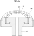
- FIG. 14 is a view schematically illustrating a first gear according to a second embodiment of the disclosure.
- the plurality of first magnet units of the first magnet 210 disposed on the first gear 140 may be spaced apart from each other in the circumferential direction, and the plurality of second magnet units of the second magnet 220 may be spaced apart from each other in the circumferential direction.
- the plurality of first magnet units of the first magnet 210 may be individually mounted in a plurality of grooves formed in the inner surface of the outer part 143.
- the plurality of second magnet units of the second magnet 220 may be individually mounted in a plurality of grooves formed in the outer surface of the inner part 143.
- the second embodiment of the disclosure may enhance the stability of the product by increasing the coupling force of the magnets 200 to the first gear 140 as compared to the first embodiment.
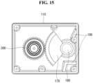
- FIG. 15 is a cross-sectional view illustrating a valve actuator according to a third embodiment of the disclosure.
- a valve actuator may include a housing 110, a motor 120 disposed on the housing 110, a drive gear 300 coupled to a motor shaft of the motor 120, an output gear 170 coupled to an output shaft 180 and engaging with the drive gear 300, and a stopper 190 disposed in the housing 110 and limiting a rotation radius of the output gear 170.
- valve actuator according to the third embodiment of the disclosure omits the transfer gears 140, 150, and 160 of the valve actuator 20, and the magnets 200 are installed in the drive gear 130.
- the drive gear 300 may be coupled to the motor shaft of the motor 120 and may be rotated in a first direction or second direction by the motor 120.
- the drive gear 300 may engage with the output gear 170 to rotate the output gear 170 at a predetermined gear ratio.
- the drive gear 300 may include an outer part, an inner part disposed inside the outer part, a first magnet disposed on the outer part, and a second magnet disposed on the inner part and facing the first magnet.
- the inner part of the drive gear 300 may be coupled to the motor shaft of the motor 120, and the outer part of the drive gear 300 may engage with the output gear 170.
- the inner part of the drive gear 300 idles with respect to the outer part 143 of the drive gear 300 due to the first magnet and the second magnet of the drive gear 300, preventing damage to the drive gear 300 and the output gear 170.
- the inner part of the drive gear 300 idles with respect to the outer part of the drive gear 300 due to the first magnet and the second magnet of the drive gear 300, damping the torque of the motor 120 applied due to the over-output and hence preventing damage to the drive gear 130 and the output gear 170.
- the inner part of the drive gear 300 may be coupled to the motor shaft of the motor 120 to rotate together with the motor shaft.
- the upper end or the lower end of the outer part of the drive gear 300 may be vertically supported by the inner part of the drive gear 300.
- the height of the first magnet of the drive gear 300 is larger than the height of the second magnet of the drive gear 300.
- a vertical center of the first magnet of the drive gear 300 may be disposed above a vertical center of the second magnet of the drive gear 300.
- a vertical center of the first magnet of the drive gear 300 may be disposed below a vertical center of the second magnet of the drive gear 300.
- the inner part of the drive gear 300 may include a groove formed in an area supporting the upper end or the lower end of the outer part of the drive gear 300.
- Lubricant may be placed in the groove. The lubricant may perform lubrication to prevent damage to the components under the high-speed slip condition.
- FIG. 16 is a perspective view illustrating some components of a valve actuator according to a fourth embodiment of the disclosure.
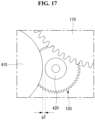
- FIG. 17 is a plan view illustrating some components of a valve actuator according to the fourth embodiment of the disclosure.
- a valve actuator may include a housing 110, a motor 120 disposed on the housing 110, a drive gear 130 coupled to a motor shaft of the motor 120, transfer gears 140 and 150 engaging with the drive gear 130 and rotating according to a first gear ratio when the drive gear 130 rotates, an output gear 170 coupled to an output shaft 180 and engaging with the transfer gears 140 and 150, and a stopper 190 disposed in the housing 110 and limiting a rotation radius of the output gear 170.
- the transfer gears 140 and 150 may include a first transfer gear 140, which engages with the drive gear 130 and rotates according to a first gear ratio with respect to the drive gear 130 when the drive gear 130 rotates, and a second transfer gear 150, which rotates according to a second gear ratio with respect to the first transfer gear 140 when the first transfer gear 140 rotates.
- the second transfer gear 150 may engage with the output gear 170.
- the transfer gears 140 and 150 may include a cylindrical first magnet 410 disposed on the first transfer gear 140 and a cylindrical second magnet 420 disposed on the second transfer gear 150.
- the first magnet 410 may be horizontally spaced apart from the second magnet 420.
- a predetermined gap g2 may be formed between the first magnet 410 and the second magnet 420.
- the first magnet 410 and the second magnet 420 may overlap each other in a horizontal direction.
- the first transfer gear 140 idles with respect to the second transfer gear 150 due to the first magnet 410 and the second magnet 420, preventing damage to the drive gear 130, the transfer gears 140 and 150, and the output gear 170.
- the first transfer gear 140 idles with respect to the second transfer gear 150 due to the first magnet 410 and the second magnet 420, damping the torque of the motor 120 applied due to the over-output and hence preventing damage to the drive gear 130, the transfer gears 140 and 150, and the output gear 170.
- the first magnet 410 may include a plurality of first magnet units arranged in a circumferential direction
- the second magnet 420 may include a plurality of second magnet units arranged in a circumferential direction.
- the plurality of first magnet units may be magnetized to have different poles from neighboring magnet units, and the plurality of second magnet units may be magnetized to have different poles from neighboring magnet units.
- the first magnet unit and the second magnet unit facing each other, among the plurality of first magnet units and the plurality of second magnet units, may have different polarities.
- the ratio of the number of the plurality of first magnet units to the number of the plurality of second magnet units may be identical to the second gear ratio.
- a valve actuator may include a housing 110, a motor 120 disposed on the housing 110, a drive gear 130 coupled to a motor shaft of the motor 120, a cylindrical first magnet 410 coupled to the drive gear 130, an output gear 170 coupled to an output shaft 180, a cylindrical second magnet 420 coupled to the output gear 170, and a stopper 190 disposed in the housing 110 and limiting a rotation radius of the output gear 170.
- valve actuator according to the fifth embodiment of the disclosure omits the transfer gears 140 and 150 of the valve actuator according to the fourth embodiment of the disclosure, and the first magnet 410 is coupled to the drive gear 130, and the second magnet 420 is coupled to the output gear 170.
Landscapes
- Engineering & Computer Science (AREA)
- General Engineering & Computer Science (AREA)
- Mechanical Engineering (AREA)
- Physics & Mathematics (AREA)
- Electromagnetism (AREA)
- Power Engineering (AREA)
- Connection Of Motors, Electrical Generators, Mechanical Devices, And The Like (AREA)
Description
- The disclosure relates to a valve actuator. More particularly, the disclosure relates to a valve actuator for opening and closing a ball valve.
- Typically, a ball valve is an opening/closing means that is widely used to supply or cut off the supply of a working fluid to a required place through a pipe coupled to two opposite sides of the main body of the valve by opening and closing the pipe by automatically rotating a ball thereinside by way of a motor.
- A conventional ball valve actuator connects the shaft of the gear motor with the output shaft of the ball valve through a cam and uses a sensor or step motor to turn the output shaft by an intended angle. In this case, a physical stopper is used to limit the rotation angle of the output shaft.
- However, if torque is applied from the motor with the gear in contact with the stopper, the gear may be damaged.
- To address this issue,
Korean Patent No. 0392198 - In this case, due to addition of components, such as a separate sensor for detecting contact of the gear to the stopper, a separate limiter switch, or a separate printed circuit board (PCB) for stop signals, the size of the product and manufacturing costs may increase.
- (Patent Document 1)
Korean Patent No. 10-0392198B1 registered on July 22, 2003 -
DE 11 2015 003071 T5 discloses a double offset valve in which a rotation shaft is eccentrically disposed from a center of a valve hole of a valve seat, and a sealing surface of the valve element is eccentrically disposed from the rotation shaft.US 2010/170763 A1 discloses a transmission device with overload protection.US 4 808 869 A discloses a motor with an integral magnetic torque limiting coupling.DE 11 2018 004762 T5 discloses a double eccentric valve including a valve element provided with a rotatable shaft eccentrically disposed from a center of a valve opening of a valve seat.KR 101 611 977 B1 GB 2 340 209 A - An object of the disclosure is to provide a valve actuator capable of preventing damage to a gear when torque is applied from a motor with the gear in contact with a stopper.
- Another object of the disclosure is to provide a valve actuator capable of damping the torque of a motor applied due to over-output.
- Another object of the disclosure is to provide a valve actuator capable of reducing manufacturing costs.
- Another object is to provide a valve actuator capable of operating even under a high-speed slip condition, e.g., at thousands of rpm.
- Another object of the disclosure is to provide a valve actuator capable of lubricating a component to prevent damage to the component under a high-speed slip condition.
- The present invention is defined by the appended independent claim, and preferred aspects of the present invention are defined by the appended dependent claims. According to an aspect of the disclosure, a valve actuator comprises a housing, a motor disposed on the housing, a drive gear coupled to a motor shaft of the motor, a transfer gear engaging with the drive gear and rotating according to a predetermined gear ratio when the drive gear rotates, an output gear coupled to an output shaft and engaging with the transfer gear, and a stopper disposed in the housing and limiting a rotation of the output gear.
- The transfer gear comprises an outer part, an inner part disposed in the outer part, a first magnet disposed on the outer part, and a second magnet disposed on the inner part and facing the first magnet.
- Thus, since the gear shaft idles due to the first magnet and the second magnet when the torque of the motor is applied, with the output gear and the stopper in contact with each other, it is possible to prevent damage to the drive gear, transfer gear, and output gear.
- It is also possible to prevent damage to the gears without separate components, such as a sensor for detecting contact of the gear to the stopper, a limiter switch, or a PCB for stop signals, thus reducing the size and manufacturing costs of the product.
- The first magnet and the second magnet may have different polarities.
- An attractive force between the first magnet and the second magnet may be larger than an average output force of the motor and smaller than a maximum output force of the motor. Thus, since the gear shaft idles due to the first magnet and the second magnet during over-output of the motor, it is possible to damp the torque of the motor applied due to over-output and hence prevent damage to the drive gear, transfer gear, and output gear.
- The first magnet may comprise a plurality of first magnet units having different polarities between adjacent magnet units, and the second magnet may comprise a plurality of second magnet units having different polarities between adjacent magnet units and individually facing the plurality of first magnet units.
- The motor may be a DC motor. In other words, since it may be applied to DC motors that are inexpensive as compared with AC motors, it is possible to reduce the manufacturing costs of the product.
- An upper end and lower end of the inner part are supported by an inner surface of the housing. An upper or lower end of the outer part is vertically supported by the inner part. A height of the first magnet is larger than a height of the second magnet. Thus, since the outer part is prevented from escaping off while maintaining a floating state with respect to the inner part, it may operate even under a high-speed slip condition, e.g., at thousands of rpm.
- When the upper end of the outer part is vertically supported by the inner part, a vertical center of the first magnet may be disposed above a vertical center of the second magnet, and when the lower end of the outer part is vertically supported by the inner part, the vertical center of the first magnet may be disposed below the vertical center of the second magnet.
- The inner part may comprise a groove formed in a region supporting the upper end or lower end of the outer part. A lubricant may be disposed in the groove. The lubricant may perform lubrication to prevent damage to the components under the high-speed slip condition.
- The transfer gear may comprise a first gear engaging with the drive gear, a second gear engaging with the first gear, and a third gear engaging with the second gear. The first gear may comprise the outer part, the inner part, the first magnet, and the second magnet.
- According to an aspect of the disclosure not falling into the scope of claim 1, a valve actuator may comprise a housing, a motor disposed on the housing, a drive gear coupled to a motor shaft of the motor, an output gear coupled to an output shaft and engaging with the drive gear, and a stopper disposed in the housing and limiting a rotation radius of the output gear.
- The drive gear may comprise an outer part, an inner part disposed in the outer part, a first magnet disposed on the outer part, and a second magnet disposed on the inner part and facing the first magnet.
- Thus, since the gear shaft idles due to the first magnet and the second magnet when the torque of the motor is applied, with the output gear and the stopper in contact with each other, it is possible to prevent damage to the drive gear and output gear.
- It is also possible to prevent damage to the gears without separate components, such as a sensor for detecting contact of the gear to the stopper, a limiter switch, or a PCB for stop signals, thus reducing the size and manufacturing costs of the product.
- Further, since the gear shaft idles due to the first magnet and the second magnet during over-output of the motor, it is possible to damp the torque of the motor applied due to over-output and hence prevent damage to the drive gear and output gear.
- The inner part may be coupled to a motor shaft and rotate along with the motor shaft. An upper or lower end of the outer part is vertically supported by the inner part. A height of the first magnet may be larger than a height of the second magnet. Thus, since the outer part is prevented from escaping off while maintaining a floating state with respect to the inner part, it may operate even under a high-speed slip condition, e.g., at thousands of rpm.
- When the upper end of the outer part is vertically supported by the inner part, a vertical center of the first magnet may be disposed above a vertical center of the second magnet, and when the lower end of the outer part is vertically supported by the inner part, the vertical center of the first magnet may be disposed below the vertical center of the second magnet.
- The inner part may comprise a groove formed in an area supporting the upper end or lower end of the outer part. A lubricant may be disposed in the groove. The lubricant may perform lubrication to prevent damage to the components under the high-speed slip condition.
- According to an aspect of the disclosure, a valve actuator may comprise a housing, a motor disposed on the housing, a drive gear coupled to a motor shaft of the motor, a transfer gear engaging with the drive gear and rotating according to a first gear ratio when the drive gear rotates, an output gear coupled to an output shaft and engaging with the transfer gear, and a stopper disposed in the housing and limiting a rotation radius of the output gear.
- The transfer gear may comprise a first transfer gear, a second transfer gear rotating according to a second gear ratio when the first transfer gear rotates, a cylindrical first magnet disposed on the first transfer gear, and a cylindrical second magnet disposed on the second transfer gear. The first magnet and the second magnet may horizontally overlap each other, with a predetermined gap formed therebetween.
- Thus, since the gear shaft idles due to the first magnet and the second magnet when the torque of the motor is applied, with the output gear and the stopper in contact with each other, it is possible to prevent damage to the drive gear, transfer gear, and output gear.
- It is also possible to prevent damage to the gears without separate components, such as a sensor for detecting contact of the gear to the stopper, a limiter switch, or a PCB for stop signals, thus reducing the size and manufacturing costs of the product.
- Further, since the gear shaft idles due to the first magnet and the second magnet during over-output of the motor, it is possible to damp the torque of the motor applied due to over-output and hence prevent damage to the drive gear, transfer gear, and output gear.
- According to an aspect of the disclosure not failing into the scope of claim 1, a valve actuator may comprise a housing, a motor disposed on the housing, a drive gear coupled to a motor shaft of the motor, a cylindrical first magnet coupled to the drive gear, an output gear coupled to an output shaft, a cylindrical second magnet coupled to the output gear, and a stopper disposed in the housing and limiting a rotation radius of the output gear.
- The first magnet and the second magnet horizontally overlap each other, with a predetermined gap formed therebetween.
- Thus, since the gear shaft idles due to the first magnet and the second magnet when the torque of the motor is applied, with the output gear and the stopper in contact with each other, it is possible to prevent damage to the drive gear and output gear.
- It is also possible to prevent damage to the gears without separate components, such as a sensor for detecting contact of the gear to the stopper, a limiter switch, or a PCB for stop signals, thus reducing the size and manufacturing costs of the product.
- Further, since the gear shaft idles due to the first magnet and the second magnet during over-output of the motor, it is possible to damp the torque of the motor applied due to over-output and hence prevent damage to the drive gear and output gear.
- The first magnet may comprise a plurality of first magnet units circumferentially arranged, and the second magnet may comprise a plurality of second magnet units circumferentially arranged. The plurality of first magnet units may be magnetized to have different poles from neighboring magnet units, and the plurality of second magnet units may be magnetized to have different poles from neighboring magnet units. The first magnet unit and the second magnet unit facing each other, among the plurality of first magnet units and the plurality of second magnet units, may have different polarities.
- The ratio of the number of the plurality of first magnet units to the number of the plurality of second magnet units may be identical to the second gear ratio.
- According to the disclosure, it is possible to provide a valve actuator capable of preventing damage to a gear when torque is applied from a motor with the gear in contact with a stopper.
- It is also possible to provide a valve actuator capable of damping the torque of a motor applied due to over-output.
- It is also possible to provide a valve actuator capable of reducing manufacturing costs.
- It is also possible to provide a valve actuator capable of operating even under a high-speed slip condition, e.g., at thousands of rpm.
- It is also possible to provide a valve actuator capable of lubricating a component to prevent damage to the component under a high-speed slip condition.
- A more complete appreciation of the disclosure and many of the attendant aspects thereof will be readily obtained as the same becomes better understood by reference to the following detailed description when considered in connection with the accompanying drawings, wherein:
-
FIG. 1 is a front view illustrating a ball valve and a valve actuator according to a first embodiment of the disclosure; -
FIG. 2 is a perspective view illustrating a valve actuator according to the first embodiment of the disclosure; -
FIG. 3 is an exploded perspective view illustrating a valve actuator according to the first embodiment of the disclosure; -
FIGS. 4 and5 are perspective views illustrating some components of a valve actuator according to the first embodiment of the disclosure; -
FIG. 6 is a perspective view illustrating a first gear according to the first embodiment of the disclosure; -
FIG. 7 is a plan view illustrating a first gear according to the first embodiment of the disclosure; -
FIG. 8 is a cross-sectional view illustrating a valve actuator according to the first embodiment of the disclosure; -
FIG. 9 is an enlarged view illustrating some components ofFIG. 8 ; -
FIGS. 10 ,11 , and12 are views illustrating the operation of a valve actuator according to the first embodiment of the disclosure; -
FIG. 13 is an exploded perspective view illustrating a ball valve according to the first embodiment of the disclosure; -
FIG. 14 is a view schematically illustrating a first gear according to a second embodiment of the disclosure; -
FIG. 15 is a cross-sectional view illustrating a valve actuator according to a third embodiment of the disclosure; -
FIG. 16 is a perspective view illustrating some components of a valve actuator according to a fourth embodiment of the disclosure; and -
FIG. 17 is a plan view illustrating some components of a valve actuator according to the fourth embodiment of the disclosure. - Hereinafter, exemplary embodiments of the disclosure are described in detail with reference to the accompanying drawings. The same reference denotations may be used to refer to the same or similar elements throughout the specification and the drawings, and no duplicate description is given.
- It will be understood that when an element or layer is referred to as being "on," "connected to," "coupled to," or "adjacent to" another element or layer, it can be directly on, connected, coupled, or adj acent to the other element or layer, or intervening elements or layers may be present.
- When determined to make the subject matter of the disclosure unclear, the detailed description of the known art or functions may be skipped. The accompanying drawings are provided merely for a better understanding of the disclosure, and the scope of the present invention are not limited by the drawings.
-
FIG. 1 is a front view illustrating a ball valve and a valve actuator according to a first embodiment of the disclosure.FIG. 2 is a perspective view illustrating a valve actuator according to the first embodiment of the disclosure.FIG. 3 is an exploded perspective view illustrating a valve actuator according to the first embodiment of the disclosure.FIGS. 4 and5 are perspective views illustrating some components of a valve actuator according to the first embodiment of the disclosure.FIG. 6 is a perspective view illustrating a first gear according to the first embodiment of the disclosure.FIG. 7 is a plan view illustrating a first gear according to the first embodiment of the disclosure.FIG. 8 is a cross-sectional view illustrating a valve actuator according to the first embodiment of the disclosure.FIG. 9 is an enlarged view illustrating some components ofFIG. 8 .FIGS. 10 ,11 , and12 are views illustrating the operation of a valve actuator according to the first embodiment of the disclosure.FIG. 13 is an exploded perspective view illustrating a ball valve according to the first embodiment of the disclosure. - Referring to
FIGS. 1 to 13 , according to the first embodiment of the disclosure, avalve actuator 20 may include ahousing 110, amotor 120, adrive gear 130, transfer gears 140, 150, and 160, anoutput gear 170, anoutput shaft 180, astopper 190, and amagnet 200. However, thevalve actuator 20 may omit some of the components or add more components. - The
valve actuator 20 may be coupled to an upper portion of aplate 11 coupled to an upper portion of aball valve 10. Theoutput shaft 180 of theactuator 20 may be coupled to astem 13 of theball valve 10. As theoutput shaft 180 of theactuator 20 rotates, thestem 13 may rotate, and aball 16 of theball valve 10 may rotate, opening or closing theball valve 10. Theball valve 10 may include astem fixing part 15 for coupling thestem 13 and an O-ring 14 disposed under thestem 13. - The
housing 110 may be formed in a hexahedral shape. Thehousing 110 may form the exterior of thevalve actuator 20. Thehousing 110 may be disposed on one side of theball valve 10. Thehousing 110 may be disposed on theball valve 10. In thehousing 110, themotor 120, thedrive gear 130, the transfer gears 140, 150, and 160, theoutput gear 170, theoutput shaft 180, and thestopper 190 may be disposed. - The
motor 120 may be disposed on thehousing 110. Themotor 120 may be coupled to a recess of thehousing 110 so that one side thereof may be disposed in thehousing 110, and the other side may protrude to the outside of thehousing 110. This may enhance space efficiency. Thedrive gear 130 may be coupled to a motor shaft of themotor 120. - The
motor 120 may a direct current (DC) motor. Themotor 120 may be an alternating current (AC) motor. When themotor 120 is a DC motor, the manufacturing costs of thevalve actuator 20 may be reduced as compared with when themotor 120 is an AC motor. A DC motor may present poor rpm control accuracy as compared with an AC motor, and this may be supplemented by thephysical stopper 190 of the valve actuator. - The
drive gear 130 may be coupled to the motor shaft of themotor 120. When the motor shaft of themotor 120 rotates in a first direction, thedrive gear 130 may rotate in the first direction and, when the motor shaft rotates in a second direction, thedrive gear 130 may rotate in the second direction. Thedrive gear 130 may engage with the transfer gears 140, 150, and 160. Thedrive gear 130 may be an external gear. - The transfer gears 140, 150, and 160 may engage with the
drive gear 130. The transfer gears 140, 150, and 160 may rotate according to a predetermined gear ratio when thedrive gear 130 rotates. The transfer gears 140, 150, and 160 may engage with theoutput gear 170. The transfer gears 140, 150, and 160 may reduce the speed of thedrive gear 130 at a predetermined gear ratio and transfer it to theoutput gear 170. Thus, the transfer gears 140, 150, and 160 may increase the torque transferred from thedrive gear 130 and transfer it to theoutput gear 170. - The transfer gears 140, 150, and 160 may include a
first gear 140, asecond gear 150, and athird gear 160. - The
first gear 140 may engage with thedrive gear 130. Thefirst gear 140 may engage with thesecond gear 150. Thefirst gear 140 may engage with thedrive gear 130 and may rotate at a predetermined gear ratio with respect to thedrive gear 130. Thefirst gear 140 may engage with thesecond gear 150 to rotate thesecond gear 150 at a predetermined gear ratio with respect to thefirst gear 140. - The
first gear 140 may include anouter part 141, a firstexternal gear 142, aninner part 143, a secondexternal gear 144, andmagnets 200. - The
outer part 141 may be disposed outside theinner part 143. Theouter part 141 may be radially spaced apart from theinner part 143. The firstexternal gear 142 may be formed on theouter part 141. Thefirst magnet 210 may be disposed on theouter part 141. - The first
external gear 142 may engage with thedrive gear 130. Thus, theouter part 141 of thefirst gear 140 may rotate at a predetermined gear ratio with respect to thedrive gear 130. - The
magnets 200 may include afirst magnet 210 disposed on theouter part 141 and asecond magnet 220 disposed on theinner part 143. Thefirst magnet 210 may be radially spaced apart from thesecond magnet 220. For example, a predetermined gap g1 may be formed between the inner surface of thefirst magnet 210 and the outer surface of thesecond magnet 220. Thesecond magnet 220 may be disposed in thefirst magnet 210. - The
first magnet 210 and thesecond magnet 220 may have different polarities. The respective areas of thefirst magnet 210 and thesecond magnet 220, which face each other, may have different polarities. For example, if a first area of thefirst magnet 210 has an N pole, a first area of thesecond magnet 220 facing the first area of thefirst magnet 210 may have an S pole. Thefirst magnet 210 may rotate according to the rotation of theouter part 141, and thesecond magnet 220 may rotate along with thefirst magnet 210 by magnetic force. - Thus, when the torque of the
motor 120 is applied while theoutput gear 170 and thestopper 190 are in contact, theouter part 141 idles with respect to theinner part 143 due to thefirst magnet 210 and thesecond magnet 220, preventing damage to thedrive gear 130, the transfer gears 140, 150, and 160, and theoutput gear 170. - Further, it is possible to prevent damage to the
drive gear 130, the transfer gears 140, 150, and 160, and theoutput gear 170 without separate components, such as a sensor for detecting contact of theoutput gear 170 to thestopper 190, a limiter switch, or a PCB for stop signals, thus reducing the size and manufacturing costs of the product. - The attractive force between the
first magnet 210 and thesecond magnet 220 may be larger than the average output of themotor 120 and smaller than the maximum output of themotor 120. Thus, when themotor 120 over-outputs, theouter part 141 idles with respect to theinner part 143 due to thefirst magnet 210 and thesecond magnet 220, damping the torque of themotor 120 applied due to the over-output and hence preventing damage to thedrive gear 130, the transfer gears 140, 150, and 160, and theoutput gear 170. In particular, this may compensate for the over-output of themotor 120 that may occur if themotor 120 is formed of a low-cost DC motor. - The
first magnet 210 may include a plurality offirst magnet units second magnet 220 may include a plurality ofsecond magnet units first magnet units 1th magnet unit 212 may have an N pole, a 1-2th magnet unit 214 may have an S pole, a 1-3th magnet unit 216 may have an N pole, and a 1-4th magnet unit 218 may have an S pole. A 2-1th magnet unit 222 may have an S pole, a 2-2th magnet unit 224 may have an N pole, a 2-3th magnet unit 226 may have an S pole, and a 2-4th magnet unit 228 may have an N pole. In the first embodiment of the disclosure, the number of the plurality offirst magnet units second magnet units - The
inner part 143 may be disposed in theouter part 141. Theinner part 143 may be radially spaced apart from theouter part 141. The secondexternal gear 144 may be formed on theinner part 143. Thesecond magnet 220 may be disposed on theouter part 143. Theouter part 143 may rotate according to the rotation of thesecond magnet 220. - An upper end and lower end of the
inner part 143 are supported by the inner surface of thehousing 110, and an upper or lower end of the outer part 131 is vertically supported by theinner part 143. The height of thefirst magnet 210 is larger than the height of thesecond magnet 220. Thus, since theouter part 141 is prevented from escaping off while maintaining a floating state with respect to theinner part 143, it may operate even under a high-speed slip condition, e.g., at thousands of rpm. - As illustrated in
FIG. 8 , when the lower end of theouter part 141 is vertically supported by theinner part 143, a vertical center of thefirst magnet 210 may be disposed below a vertical center of thesecond magnet 220. - Alternatively, when the upper end of the
outer part 141 is vertically supported by theinner part 143, the vertical center of thefirst magnet 210 may be disposed above the vertical center of thesecond magnet 220. - The
inner part 143 may includegrooves outer part 141. In this case, thevalve actuator 20 may include a lubricant disposed in thegrooves inner part 143 and theouter part 141 to prevent damage to theinner part 143 and theouter part 141 under the high-speed slip condition. - The second
external gear 144 may be formed on theinner part 143. The secondexternal gear 144 may be vertically spaced apart from the firstexternal gear 142. This may enhance space efficiency. A radial size of the secondexternal gear 144 may be smaller than a radial size of the firstexternal gear 142. The secondexternal gear 144 may engage with thesecond gear 150. The secondexternal gear 144 may rotate thesecond gear 150 at a predetermined gear ratio with respect to thefirst gear 140. - The
second gear 150 may engage with thefirst gear 140. Thesecond gear 150 may engage with thethird gear 160. Thesecond gear 150 may engage with thefirst gear 140 and may rotate at a predetermined gear ratio with respect to thefirst gear 140. Thesecond gear 150 may engage with thethird gear 160 to rotate thethird gear 160 at a predetermined gear ratio with respect to thesecond gear 150. - The
second gear 150 may include a thirdexternal gear 152 and a fourthexternal gear 154. The thirdexternal gear 152 may engage with the secondexternal gear 144 of thefirst gear 140, and the fourthexternal gear 154 may engage with thethird gear 160. The thirdexternal gear 152 and the fourthexternal gear 154 may be vertically spaced apart from each other. This may enhance space efficiency. A radial size of the fourthexternal gear 154 may be smaller than a radial size of the thirdexternal gear 152. - The
third gear 160 may engage with thesecond gear 150. Thethird gear 160 may engage with theoutput gear 170. Thethird gear 160 may engage with thesecond gear 150 and may rotate at a predetermined gear ratio with respect to thesecond gear 150. Thethird gear 160 may engage with theoutput gear 170 to rotate theoutput gear 170 at a predetermined gear ratio with respect to thethird gear 160. - The
third gear 160 may include a fifthexternal gear 162 and a sixthexternal gear 164. The fifthexternal gear 162 may engage with the fourthexternal gear 154 of thesecond gear 150, and the sixthexternal gear 164 may engage with theoutput gear 170. The fifthexternal gear 162 and the sixthexternal gear 164 may be vertically spaced apart from each other. This may enhance space efficiency. A radial size of the fifthexternal gear 162 may be larger than a radial size of the sixthexternal gear 164. - In the embodiment of the disclosure, as an example, the transfer gears 140, 150, and 160 are described as including three gears, but the transfer gears 140, 150, and 160 may be understood as including one or more gears.
- The
output gear 170 may engage with the transfer gears 140, 150, and 160. Theoutput gear 170 may be coupled to theoutput shaft 180. The rotation radius of theoutput gear 170 may be limited by thestopper 190. Theoutput gear 170 may be rotated in one direction or another direction by the transfer gears 140, 150, and 160 to rotate theoutput shaft 180 in the one direction or the other direction. - The
output shaft 180 may be disposed in thehousing 110. Theoutput shaft 180 may pass through thehousing 110, and one side thereof may be coupled to theoutput gear 170 while the opposite side thereof may be coupled to thestem 13 of theball valve 10. Theoutput shaft 180 may be rotated in one direction or another direction by theoutput gear 170 to rotate thestem 13 of theball valve 10 in the one direction or the other direction. Thus, theball valve 10 may be opened and closed. - The
stopper 190 may be disposed in thehousing 110. Thestopper 190 may be formed on an inner surface of thehousing 110. Thestopper 190 may be disposed within a rotation radius of theoutput gear 170. Thestopper 190 may limit the rotation angle of theoutput gear 170. - The operation of the
valve actuator 20 is described with reference toFIGS. 10 to 12 . - Assuming that the state illustrated in
FIG. 10 is an initial state, the inside of theball valve 10 may be in an open state in the initial state. - Referring to
FIG. 11 , when themotor 120 rotates thedrive gear 130 in a first direction, thefirst gear 140 engaging with thedrive gear 130 may rotate in a second direction, thesecond gear 150 engaging with thefirst gear 140 may rotate in the first direction, and thethird gear 160 engaging with thesecond gear 150 may rotate in the second direction, theoutput gear 170 engaging with thethird gear 160 may rotate in the first direction, and theoutput shaft 180 coupled with theoutput gear 170 may rotate in the first direction, allowing the inside of theball valve 10 to turn into a closed state. In this case, the rotation radius of theoutput gear 170 may be limited by thestopper 190, preventing damage to theball valve 10. - Referring to
FIG. 12 , when themotor 120 rotates thedrive gear 130 in the second direction, thefirst gear 140 engaging with thedrive gear 130 may rotate in the first direction, thesecond gear 150 engaging with thefirst gear 140 may rotate in the second direction, and thethird gear 160 engaging with thesecond gear 150 may rotate in the first direction, theoutput gear 170 engaging with thethird gear 160 may rotate in the second direction, and theoutput shaft 180 coupled with theoutput gear 170 may rotate in the second direction, allowing the inside of theball valve 10 to turn into a closed state. In this case, the rotation radius of theoutput gear 170 may be limited by thestopper 190, preventing damage to theball valve 10. - As illustrated in
FIGS. 11 and12 , even when the inside of theball valve 10 is in the closed state, themotor 120 may continue to operate. In this case, theouter part 141 idles with respect to theinner part 143 due to thefirst magnet 210 and thesecond magnet 220, preventing damage to thedrive gear 130, the transfer gears 140, 150, and 160, and theoutput gear 170. - In the first embodiment of the disclosure, the
magnets 200 have been described as being disposed in thefirst gear 140 as an example, but themagnets 200 may be disposed in thesecond gear 150 or thethird gear 160. However, when themagnets 200 are disposed in thefirst gear 140, it is possible to effectively prevent damage to the product as compared to themagnets 200 disposed in thesecond gear 150 or thethird gear 160. -
FIG. 14 is a view schematically illustrating a first gear according to a second embodiment of the disclosure. - Referring to
FIG. 14 , according to the second embodiment of the disclosure, the plurality of first magnet units of thefirst magnet 210 disposed on thefirst gear 140 may be spaced apart from each other in the circumferential direction, and the plurality of second magnet units of thesecond magnet 220 may be spaced apart from each other in the circumferential direction. - The plurality of first magnet units of the
first magnet 210 may be individually mounted in a plurality of grooves formed in the inner surface of theouter part 143. The plurality of second magnet units of thesecond magnet 220 may be individually mounted in a plurality of grooves formed in the outer surface of theinner part 143. - The second embodiment of the disclosure may enhance the stability of the product by increasing the coupling force of the
magnets 200 to thefirst gear 140 as compared to the first embodiment. -
FIG. 15 is a cross-sectional view illustrating a valve actuator according to a third embodiment of the disclosure. - Referring to
FIG. 15 , according to the third embodiment of the disclosure, a valve actuator may include ahousing 110, amotor 120 disposed on thehousing 110, adrive gear 300 coupled to a motor shaft of themotor 120, anoutput gear 170 coupled to anoutput shaft 180 and engaging with thedrive gear 300, and astopper 190 disposed in thehousing 110 and limiting a rotation radius of theoutput gear 170. - It may be appreciated that detailed configurations of the valve actuator not described in connection with the third embodiment of the disclosure are identical the detailed configurations of the
valve actuator 20 according to the first embodiment of the disclosure. - It may be appreciated that the valve actuator according to the third embodiment of the disclosure omits the transfer gears 140, 150, and 160 of the
valve actuator 20, and themagnets 200 are installed in thedrive gear 130. - The
drive gear 300 may be coupled to the motor shaft of themotor 120 and may be rotated in a first direction or second direction by themotor 120. Thedrive gear 300 may engage with theoutput gear 170 to rotate theoutput gear 170 at a predetermined gear ratio. - The
drive gear 300 may include an outer part, an inner part disposed inside the outer part, a first magnet disposed on the outer part, and a second magnet disposed on the inner part and facing the first magnet. The inner part of thedrive gear 300 may be coupled to the motor shaft of themotor 120, and the outer part of thedrive gear 300 may engage with theoutput gear 170. - Thus, when the torque of the
motor 120 is applied while theoutput gear 170 and thestopper 190 are in contact, the inner part of thedrive gear 300 idles with respect to theouter part 143 of thedrive gear 300 due to the first magnet and the second magnet of thedrive gear 300, preventing damage to thedrive gear 300 and theoutput gear 170. - Further, it is possible to prevent damage to the
drive gear 130 and theoutput gear 170 without separate components, such as a sensor for detecting contact of theoutput gear 170 to thestopper 190, a limiter switch, or a PCB for stop signals, thus reducing the size and manufacturing costs of the product. - Further, when the
motor 120 over-outputs, the inner part of thedrive gear 300 idles with respect to the outer part of thedrive gear 300 due to the first magnet and the second magnet of thedrive gear 300, damping the torque of themotor 120 applied due to the over-output and hence preventing damage to thedrive gear 130 and theoutput gear 170. - The inner part of the
drive gear 300 may be coupled to the motor shaft of themotor 120 to rotate together with the motor shaft. The upper end or the lower end of the outer part of thedrive gear 300 may be vertically supported by the inner part of thedrive gear 300. The height of the first magnet of thedrive gear 300 is larger than the height of the second magnet of thedrive gear 300. Thus, since the outer part of thedrive gear 300 is prevented from escaping off while maintaining a floating state with respect to the inner part of thedrive gear 300, it may operate even under a high-speed slip condition, e.g., at thousands of rpm. - When the upper end of the outer part of the
drive gear 300 is vertically supported by the inner part of thedrive gear 300, a vertical center of the first magnet of thedrive gear 300 may be disposed above a vertical center of the second magnet of thedrive gear 300. - When the lower end of the outer part of the
drive gear 300 is vertically supported by the inner part of thedrive gear 300, a vertical center of the first magnet of thedrive gear 300 may be disposed below a vertical center of the second magnet of thedrive gear 300. - The inner part of the
drive gear 300 may include a groove formed in an area supporting the upper end or the lower end of the outer part of thedrive gear 300. Lubricant may be placed in the groove. The lubricant may perform lubrication to prevent damage to the components under the high-speed slip condition. -
FIG. 16 is a perspective view illustrating some components of a valve actuator according to a fourth embodiment of the disclosure.FIG. 17 is a plan view illustrating some components of a valve actuator according to the fourth embodiment of the disclosure. - Referring to
FIGS. 16 and17 , according to the fourth embodiment of the disclosure, a valve actuator may include ahousing 110, amotor 120 disposed on thehousing 110, adrive gear 130 coupled to a motor shaft of themotor 120, transfer gears 140 and 150 engaging with thedrive gear 130 and rotating according to a first gear ratio when thedrive gear 130 rotates, anoutput gear 170 coupled to anoutput shaft 180 and engaging with the transfer gears 140 and 150, and astopper 190 disposed in thehousing 110 and limiting a rotation radius of theoutput gear 170. - It may be appreciated that detailed configurations of the valve actuator not described in connection with the fourth embodiment of the disclosure are identical the detailed configurations of the
valve actuator 20 according to the first embodiment of the disclosure. - The transfer gears 140 and 150 may include a
first transfer gear 140, which engages with thedrive gear 130 and rotates according to a first gear ratio with respect to thedrive gear 130 when thedrive gear 130 rotates, and asecond transfer gear 150, which rotates according to a second gear ratio with respect to thefirst transfer gear 140 when thefirst transfer gear 140 rotates. Thesecond transfer gear 150 may engage with theoutput gear 170. - The transfer gears 140 and 150 may include a cylindrical
first magnet 410 disposed on thefirst transfer gear 140 and a cylindricalsecond magnet 420 disposed on thesecond transfer gear 150. Thefirst magnet 410 may be horizontally spaced apart from thesecond magnet 420. For example, a predetermined gap g2 may be formed between thefirst magnet 410 and thesecond magnet 420. Thefirst magnet 410 and thesecond magnet 420 may overlap each other in a horizontal direction. - Thus, when the torque of the
motor 120 is applied while theoutput gear 170 and thestopper 190 are in contact, thefirst transfer gear 140 idles with respect to thesecond transfer gear 150 due to thefirst magnet 410 and thesecond magnet 420, preventing damage to thedrive gear 130, the transfer gears 140 and 150, and theoutput gear 170. - Further, it is possible to prevent damage to the
drive gear 130, the transfer gears 140 and 150, and theoutput gear 170 without separate components, such as a sensor for detecting contact of theoutput gear 170 to thestopper 190, a limiter switch, or a PCB for stop signals, thus reducing the size and manufacturing costs of the product. - Further, when the
motor 120 over-outputs, thefirst transfer gear 140 idles with respect to thesecond transfer gear 150 due to thefirst magnet 410 and thesecond magnet 420, damping the torque of themotor 120 applied due to the over-output and hence preventing damage to thedrive gear 130, the transfer gears 140 and 150, and theoutput gear 170. - The
first magnet 410 may include a plurality of first magnet units arranged in a circumferential direction, and thesecond magnet 420 may include a plurality of second magnet units arranged in a circumferential direction. - The plurality of first magnet units may be magnetized to have different poles from neighboring magnet units, and the plurality of second magnet units may be magnetized to have different poles from neighboring magnet units. The first magnet unit and the second magnet unit facing each other, among the plurality of first magnet units and the plurality of second magnet units, may have different polarities. The ratio of the number of the plurality of first magnet units to the number of the plurality of second magnet units may be identical to the second gear ratio.
- According to the fifth embodiment of the disclosure, a valve actuator may include a
housing 110, amotor 120 disposed on thehousing 110, adrive gear 130 coupled to a motor shaft of themotor 120, a cylindricalfirst magnet 410 coupled to thedrive gear 130, anoutput gear 170 coupled to anoutput shaft 180, a cylindricalsecond magnet 420 coupled to theoutput gear 170, and astopper 190 disposed in thehousing 110 and limiting a rotation radius of theoutput gear 170. - It may be appreciated that detailed configurations of the valve actuator not described in connection with the fifth embodiment of the disclosure are identical the detailed configurations of the valve actuator according to the fourth embodiment of the disclosure.
- It may be appreciated that the valve actuator according to the fifth embodiment of the disclosure omits the transfer gears 140 and 150 of the valve actuator according to the fourth embodiment of the disclosure, and the
first magnet 410 is coupled to thedrive gear 130, and thesecond magnet 420 is coupled to theoutput gear 170. - The above description should be interpreted not as limiting in all aspects but as exemplary. The scope of the present invention should be determined by interpretations of the appended claims.
Claims (9)
- A valve actuator, comprising:a housing (110);a motor (120) disposed on the housing (110);a drive gear (130) coupled to a motor shaft of the motor (120);a transfer gear (140, 150, 160) engaging with the drive gear (130) and rotating according to a predetermined gear ratio when the drive gear (130) rotates;an output gear (170) coupled to an output shaft (180) and engaging with the transfer gear (140, 150, 160); anda stopper (190) disposed in the housing (110) and limiting a rotation of the output gear (170),characterized in that the transfer gear (140, 150, 160) comprises an outer part (141), an inner part (143) disposed in the outer part (141), a first magnet (210) disposed on the outer part (141), and a second magnet (220) disposed on the inner part (143) and facing the first magnet (210), and in that an upper end and a lower end of the inner part (143) are supported by an inner surface of the housing (110), an upper or a lower end of the outer part (141) is vertically supported by the inner part (143), and a height of the first magnet (210) is larger than a height of the second magnet (220).
- The valve actuator of claim 1, wherein the first magnet (210) and the second magnet (220) have different polarities.
- The valve actuator of claim 1 or 2, wherein an attractive force between the first magnet (210) and the second magnet (220) is larger than an average output force of the motor (120) and smaller than a maximum output force of the motor (120).
- The valve actuator of one of preceding claims, wherein the first magnet (210) comprises a plurality of first magnet units (212, 214, 216, 218) having different polarities between adjacent magnet units, and the second magnet (220) comprises a plurality of second magnet units (222, 224, 226, 228) having different polarities between adjacent magnet units and individually facing the plurality of first magnet units (212, 214, 216, 218).
- The valve actuator of one of preceding claims, wherein the motor (120) is a direct current (DC) motor.
- The valve actuator of any one of the preceding claims, wherein when the upper end of the outer part (141) is vertically supported by the inner part (143), a vertical center of the first magnet (210) is disposed above a vertical center of the second magnet (220), and
wherein when the lower end of the outer part (141) is vertically supported by the inner part (143), the vertical center of the first magnet (210) is disposed below the vertical center of the second magnet (220). - The valve actuator of any one of the preceding claims, wherein the inner part (143) comprises a groove (1431, 1433) formed in a region supporting the upper end or the lower end of the outer part (141).
- The valve actuator of claim 7, wherein a lubricant is disposed in the groove (1431, 1433).
- The valve actuator of one of preceding claims, wherein the transfer gear (140, 150, 160) includes:a first gear (140) engaging with the drive gear (130),a second gear (150) engaging with the first gear (140), anda third gear (160) engaging with the second gear (150), andwherein the first gear (140) includes the outer part (141), the inner part (143), the first magnet (210), and the second magnet (220).
Applications Claiming Priority (1)
| Application Number | Priority Date | Filing Date | Title |
|---|---|---|---|
| KR1020210110070A KR102565392B1 (en) | 2021-08-20 | 2021-08-20 | Valve actuator |
Publications (2)
| Publication Number | Publication Date |
|---|---|
| EP4137727A1 EP4137727A1 (en) | 2023-02-22 |
| EP4137727B1 true EP4137727B1 (en) | 2024-11-13 |
Family
ID=79185807
Family Applications (1)
| Application Number | Title | Priority Date | Filing Date |
|---|---|---|---|
| EP21218051.7A Active EP4137727B1 (en) | 2021-08-20 | 2021-12-29 | Valve actuator |
Country Status (3)
| Country | Link |
|---|---|
| US (1) | US12104714B2 (en) |
| EP (1) | EP4137727B1 (en) |
| KR (1) | KR102565392B1 (en) |
Family Cites Families (14)
| Publication number | Priority date | Publication date | Assignee | Title |
|---|---|---|---|---|
| US4754949A (en) * | 1987-09-08 | 1988-07-05 | Rikuo Fukamachi | Actuator for valve |
| US4808869A (en) * | 1987-11-18 | 1989-02-28 | Sundstrand Corp. | Integral magnetic torque limiting coupling/motor |
| US6098957A (en) * | 1998-07-31 | 2000-08-08 | Honeywell Inc. | Electro-mechanical torque limiter for valve actuators |
| US6097123A (en) * | 1999-06-03 | 2000-08-01 | Johnson Controls Technology Company | Brake and stall detector for a motorized actuator |
| US6173939B1 (en) * | 1999-11-10 | 2001-01-16 | Ford Global Technologies, Inc. | Electronic throttle control system with two-spring failsafe mechanism |
| JP3742855B2 (en) * | 2000-03-14 | 2006-02-08 | ダイキン工業株式会社 | Rotary four-way valve |
| KR100392198B1 (en) | 2001-07-02 | 2003-07-22 | 주식회사 코텍 | Electromotion ball valve |
| KR20070070498A (en) * | 2005-12-29 | 2007-07-04 | 세메스 주식회사 | How to control a valve and fluid flow in the valve |
| JP2009138856A (en) * | 2007-12-06 | 2009-06-25 | Tgk Co Ltd | Electrically-driven valve |
| CN101766914A (en) * | 2009-01-07 | 2010-07-07 | 鸿富锦精密工业(深圳)有限公司 | transmission |
| WO2016002599A1 (en) * | 2014-06-30 | 2016-01-07 | 愛三工業株式会社 | Double eccentric valve |
| KR101611977B1 (en) * | 2014-10-10 | 2016-04-12 | 주식회사 현대케피코 | Actuator with impact absorbing type stopper |
| KR101616578B1 (en) | 2015-01-23 | 2016-04-28 | 캄텍주식회사 | An actuator for a vechicle |
| JP6859233B2 (en) * | 2017-08-31 | 2021-04-14 | 愛三工業株式会社 | Double eccentric valve |
-
2021
- 2021-08-20 KR KR1020210110070A patent/KR102565392B1/en active Active
- 2021-12-29 EP EP21218051.7A patent/EP4137727B1/en active Active
-
2022
- 2022-01-06 US US17/570,130 patent/US12104714B2/en active Active
Also Published As
| Publication number | Publication date |
|---|---|
| KR102565392B1 (en) | 2023-08-09 |
| KR20230027834A (en) | 2023-02-28 |
| US12104714B2 (en) | 2024-10-01 |
| EP4137727A1 (en) | 2023-02-22 |
| CN115929980A (en) | 2023-04-07 |
| US20230057656A1 (en) | 2023-02-23 |
Similar Documents
| Publication | Publication Date | Title |
|---|---|---|
| CN104033384A (en) | Scroll compressor | |
| EP3561302A1 (en) | Co-rotating scroll compressor | |
| JP5150319B2 (en) | Valve actuator | |
| EP4160063B1 (en) | Valve actuator | |
| CN111433477B (en) | Electromagnetic clutch and gearbox | |
| EP4137727A1 (en) | Valve actuator | |
| EP2893231B1 (en) | Magnetic holding brake and actuator with a magnetic holding brake | |
| EP1552177B1 (en) | Clutch having a variable viscosity fluid | |
| JPWO2019026340A1 (en) | Vacuum pump | |
| US7246579B2 (en) | Actuator for valve lift controller | |
| CN115929980B (en) | Valve actuator | |
| WO2018116685A1 (en) | Scroll compressor | |
| JP2007285483A (en) | Actuator with feed screw mechanism | |
| US20240102516A1 (en) | Geared motor and clutch actuator using same | |
| US7234425B2 (en) | Actuator for valve lift controller | |
| CN112701875B (en) | Ring plate type permanent magnet gear speed change transmission device | |
| KR20200004748A (en) | Scroll compressor | |
| RU2362260C2 (en) | Electromagnetic dc motor | |
| JP2025150346A (en) | Electric actuator and actuator device | |
| WO2019082123A1 (en) | Planar high torque electric motor | |
| JP6762610B2 (en) | Brushless motor | |
| CN2879517Y (en) | Magnetic clutch | |
| CN1945945A (en) | Magnetic clutch | |
| JPH11287260A (en) | One-way clutch | |
| CN114060276A (en) | compressor |
Legal Events
| Date | Code | Title | Description |
|---|---|---|---|
| PUAI | Public reference made under article 153(3) epc to a published international application that has entered the european phase |
Free format text: ORIGINAL CODE: 0009012 |
|
| STAA | Information on the status of an ep patent application or granted ep patent |
Free format text: STATUS: REQUEST FOR EXAMINATION WAS MADE |
|
| 17P | Request for examination filed |
Effective date: 20220129 |
|
| AK | Designated contracting states |
Kind code of ref document: A1 Designated state(s): AL AT BE BG CH CY CZ DE DK EE ES FI FR GB GR HR HU IE IS IT LI LT LU LV MC MK MT NL NO PL PT RO RS SE SI SK SM TR |
|
| GRAP | Despatch of communication of intention to grant a patent |
Free format text: ORIGINAL CODE: EPIDOSNIGR1 |
|
| STAA | Information on the status of an ep patent application or granted ep patent |
Free format text: STATUS: GRANT OF PATENT IS INTENDED |
|
| RIC1 | Information provided on ipc code assigned before grant |
Ipc: H02K 49/10 20060101ALI20240724BHEP Ipc: F16K 31/08 20060101ALI20240724BHEP Ipc: F16H 19/00 20060101ALI20240724BHEP Ipc: F16H 37/04 20060101ALI20240724BHEP Ipc: F16K 47/00 20060101ALI20240724BHEP Ipc: F16H 35/10 20060101ALI20240724BHEP Ipc: F16K 31/53 20060101AFI20240724BHEP |
|
| INTG | Intention to grant announced |
Effective date: 20240805 |
|
| GRAS | Grant fee paid |
Free format text: ORIGINAL CODE: EPIDOSNIGR3 |
|
| GRAA | (expected) grant |
Free format text: ORIGINAL CODE: 0009210 |
|
| STAA | Information on the status of an ep patent application or granted ep patent |
Free format text: STATUS: THE PATENT HAS BEEN GRANTED |
|
| AK | Designated contracting states |
Kind code of ref document: B1 Designated state(s): AL AT BE BG CH CY CZ DE DK EE ES FI FR GB GR HR HU IE IS IT LI LT LU LV MC MK MT NL NO PL PT RO RS SE SI SK SM TR |
|
| REG | Reference to a national code |
Ref country code: GB Ref legal event code: FG4D |
|
| REG | Reference to a national code |
Ref country code: CH Ref legal event code: EP |
|
| REG | Reference to a national code |
Ref country code: IE Ref legal event code: FG4D |
|
| REG | Reference to a national code |
Ref country code: DE Ref legal event code: R096 Ref document number: 602021021739 Country of ref document: DE |
|
| REG | Reference to a national code |
Ref country code: LT Ref legal event code: MG9D |
|
| REG | Reference to a national code |
Ref country code: NL Ref legal event code: MP Effective date: 20241113 |
|
| PG25 | Lapsed in a contracting state [announced via postgrant information from national office to epo] |
Ref country code: HR Free format text: LAPSE BECAUSE OF FAILURE TO SUBMIT A TRANSLATION OF THE DESCRIPTION OR TO PAY THE FEE WITHIN THE PRESCRIBED TIME-LIMIT Effective date: 20241113 Ref country code: IS Free format text: LAPSE BECAUSE OF FAILURE TO SUBMIT A TRANSLATION OF THE DESCRIPTION OR TO PAY THE FEE WITHIN THE PRESCRIBED TIME-LIMIT Effective date: 20250313 Ref country code: PT Free format text: LAPSE BECAUSE OF FAILURE TO SUBMIT A TRANSLATION OF THE DESCRIPTION OR TO PAY THE FEE WITHIN THE PRESCRIBED TIME-LIMIT Effective date: 20250313 |
|
| PG25 | Lapsed in a contracting state [announced via postgrant information from national office to epo] |
Ref country code: NL Free format text: LAPSE BECAUSE OF FAILURE TO SUBMIT A TRANSLATION OF THE DESCRIPTION OR TO PAY THE FEE WITHIN THE PRESCRIBED TIME-LIMIT Effective date: 20241113 Ref country code: FI Free format text: LAPSE BECAUSE OF FAILURE TO SUBMIT A TRANSLATION OF THE DESCRIPTION OR TO PAY THE FEE WITHIN THE PRESCRIBED TIME-LIMIT Effective date: 20241113 |
|
| REG | Reference to a national code |
Ref country code: AT Ref legal event code: MK05 Ref document number: 1741906 Country of ref document: AT Kind code of ref document: T Effective date: 20241113 |
|
| PG25 | Lapsed in a contracting state [announced via postgrant information from national office to epo] |
Ref country code: BG Free format text: LAPSE BECAUSE OF FAILURE TO SUBMIT A TRANSLATION OF THE DESCRIPTION OR TO PAY THE FEE WITHIN THE PRESCRIBED TIME-LIMIT Effective date: 20241113 |
|
| PG25 | Lapsed in a contracting state [announced via postgrant information from national office to epo] |
Ref country code: ES Free format text: LAPSE BECAUSE OF FAILURE TO SUBMIT A TRANSLATION OF THE DESCRIPTION OR TO PAY THE FEE WITHIN THE PRESCRIBED TIME-LIMIT Effective date: 20241113 |
|
| PG25 | Lapsed in a contracting state [announced via postgrant information from national office to epo] |
Ref country code: NO Free format text: LAPSE BECAUSE OF FAILURE TO SUBMIT A TRANSLATION OF THE DESCRIPTION OR TO PAY THE FEE WITHIN THE PRESCRIBED TIME-LIMIT Effective date: 20250213 |
|
| PG25 | Lapsed in a contracting state [announced via postgrant information from national office to epo] |
Ref country code: LV Free format text: LAPSE BECAUSE OF FAILURE TO SUBMIT A TRANSLATION OF THE DESCRIPTION OR TO PAY THE FEE WITHIN THE PRESCRIBED TIME-LIMIT Effective date: 20241113 Ref country code: GR Free format text: LAPSE BECAUSE OF FAILURE TO SUBMIT A TRANSLATION OF THE DESCRIPTION OR TO PAY THE FEE WITHIN THE PRESCRIBED TIME-LIMIT Effective date: 20250214 Ref country code: AT Free format text: LAPSE BECAUSE OF FAILURE TO SUBMIT A TRANSLATION OF THE DESCRIPTION OR TO PAY THE FEE WITHIN THE PRESCRIBED TIME-LIMIT Effective date: 20241113 |
|
| PG25 | Lapsed in a contracting state [announced via postgrant information from national office to epo] |
Ref country code: PL Free format text: LAPSE BECAUSE OF FAILURE TO SUBMIT A TRANSLATION OF THE DESCRIPTION OR TO PAY THE FEE WITHIN THE PRESCRIBED TIME-LIMIT Effective date: 20241113 |
|
| PG25 | Lapsed in a contracting state [announced via postgrant information from national office to epo] |
Ref country code: RS Free format text: LAPSE BECAUSE OF FAILURE TO SUBMIT A TRANSLATION OF THE DESCRIPTION OR TO PAY THE FEE WITHIN THE PRESCRIBED TIME-LIMIT Effective date: 20250213 |
|
| PG25 | Lapsed in a contracting state [announced via postgrant information from national office to epo] |
Ref country code: SM Free format text: LAPSE BECAUSE OF FAILURE TO SUBMIT A TRANSLATION OF THE DESCRIPTION OR TO PAY THE FEE WITHIN THE PRESCRIBED TIME-LIMIT Effective date: 20241113 |
|
| PG25 | Lapsed in a contracting state [announced via postgrant information from national office to epo] |
Ref country code: DK Free format text: LAPSE BECAUSE OF FAILURE TO SUBMIT A TRANSLATION OF THE DESCRIPTION OR TO PAY THE FEE WITHIN THE PRESCRIBED TIME-LIMIT Effective date: 20241113 |
|
| PG25 | Lapsed in a contracting state [announced via postgrant information from national office to epo] |
Ref country code: EE Free format text: LAPSE BECAUSE OF FAILURE TO SUBMIT A TRANSLATION OF THE DESCRIPTION OR TO PAY THE FEE WITHIN THE PRESCRIBED TIME-LIMIT Effective date: 20241113 |
|
| PG25 | Lapsed in a contracting state [announced via postgrant information from national office to epo] |
Ref country code: RO Free format text: LAPSE BECAUSE OF FAILURE TO SUBMIT A TRANSLATION OF THE DESCRIPTION OR TO PAY THE FEE WITHIN THE PRESCRIBED TIME-LIMIT Effective date: 20241113 |
|
| PG25 | Lapsed in a contracting state [announced via postgrant information from national office to epo] |
Ref country code: SK Free format text: LAPSE BECAUSE OF FAILURE TO SUBMIT A TRANSLATION OF THE DESCRIPTION OR TO PAY THE FEE WITHIN THE PRESCRIBED TIME-LIMIT Effective date: 20241113 |
|
| PG25 | Lapsed in a contracting state [announced via postgrant information from national office to epo] |
Ref country code: CZ Free format text: LAPSE BECAUSE OF FAILURE TO SUBMIT A TRANSLATION OF THE DESCRIPTION OR TO PAY THE FEE WITHIN THE PRESCRIBED TIME-LIMIT Effective date: 20241113 |
|
| PG25 | Lapsed in a contracting state [announced via postgrant information from national office to epo] |
Ref country code: IT Free format text: LAPSE BECAUSE OF FAILURE TO SUBMIT A TRANSLATION OF THE DESCRIPTION OR TO PAY THE FEE WITHIN THE PRESCRIBED TIME-LIMIT Effective date: 20241113 |
|
| REG | Reference to a national code |
Ref country code: CH Ref legal event code: PL |
|
| REG | Reference to a national code |
Ref country code: DE Ref legal event code: R097 Ref document number: 602021021739 Country of ref document: DE |
|
| PG25 | Lapsed in a contracting state [announced via postgrant information from national office to epo] |
Ref country code: LU Free format text: LAPSE BECAUSE OF NON-PAYMENT OF DUE FEES Effective date: 20241229 |
|
| PG25 | Lapsed in a contracting state [announced via postgrant information from national office to epo] |
Ref country code: SE Free format text: LAPSE BECAUSE OF FAILURE TO SUBMIT A TRANSLATION OF THE DESCRIPTION OR TO PAY THE FEE WITHIN THE PRESCRIBED TIME-LIMIT Effective date: 20241113 |
|
| PG25 | Lapsed in a contracting state [announced via postgrant information from national office to epo] |
Ref country code: MC Free format text: LAPSE BECAUSE OF FAILURE TO SUBMIT A TRANSLATION OF THE DESCRIPTION OR TO PAY THE FEE WITHIN THE PRESCRIBED TIME-LIMIT Effective date: 20241113 |
|
| PLBE | No opposition filed within time limit |
Free format text: ORIGINAL CODE: 0009261 |
|
| STAA | Information on the status of an ep patent application or granted ep patent |
Free format text: STATUS: NO OPPOSITION FILED WITHIN TIME LIMIT |
|
| REG | Reference to a national code |
Ref country code: BE Ref legal event code: MM Effective date: 20241231 |
|
| PG25 | Lapsed in a contracting state [announced via postgrant information from national office to epo] |
Ref country code: BE Free format text: LAPSE BECAUSE OF NON-PAYMENT OF DUE FEES Effective date: 20241231 |
|
| PG25 | Lapsed in a contracting state [announced via postgrant information from national office to epo] |
Ref country code: CH Free format text: LAPSE BECAUSE OF NON-PAYMENT OF DUE FEES Effective date: 20241231 |
|
| 26N | No opposition filed |
Effective date: 20250814 |
|
| PG25 | Lapsed in a contracting state [announced via postgrant information from national office to epo] |
Ref country code: IE Free format text: LAPSE BECAUSE OF NON-PAYMENT OF DUE FEES Effective date: 20241229 |
|
| PGFP | Annual fee paid to national office [announced via postgrant information from national office to epo] |
Ref country code: DE Payment date: 20251105 Year of fee payment: 5 |
|
| PGFP | Annual fee paid to national office [announced via postgrant information from national office to epo] |
Ref country code: FR Payment date: 20251111 Year of fee payment: 5 |
|
| PG25 | Lapsed in a contracting state [announced via postgrant information from national office to epo] |
Ref country code: CY Free format text: LAPSE BECAUSE OF FAILURE TO SUBMIT A TRANSLATION OF THE DESCRIPTION OR TO PAY THE FEE WITHIN THE PRESCRIBED TIME-LIMIT Effective date: 20241113 |