EP4137724A1 - Solenoid valve manifold - Google Patents
Solenoid valve manifold Download PDFInfo
- Publication number
- EP4137724A1 EP4137724A1 EP21788843.7A EP21788843A EP4137724A1 EP 4137724 A1 EP4137724 A1 EP 4137724A1 EP 21788843 A EP21788843 A EP 21788843A EP 4137724 A1 EP4137724 A1 EP 4137724A1
- Authority
- EP
- European Patent Office
- Prior art keywords
- block
- solenoid valve
- engaging
- connector
- wiring block
- Prior art date
- Legal status (The legal status is an assumption and is not a legal conclusion. Google has not performed a legal analysis and makes no representation as to the accuracy of the status listed.)
- Pending
Links
- NJPPVKZQTLUDBO-UHFFFAOYSA-N novaluron Chemical compound C1=C(Cl)C(OC(F)(F)C(OC(F)(F)F)F)=CC=C1NC(=O)NC(=O)C1=C(F)C=CC=C1F NJPPVKZQTLUDBO-UHFFFAOYSA-N 0.000 claims abstract description 48
- 230000005489 elastic deformation Effects 0.000 claims description 9
- 230000004308 accommodation Effects 0.000 claims description 8
- 230000004931 aggregating effect Effects 0.000 claims description 4
- 210000000078 claw Anatomy 0.000 description 2
- 238000004891 communication Methods 0.000 description 2
- 239000011347 resin Substances 0.000 description 2
- 229920005989 resin Polymers 0.000 description 2
- 238000005452 bending Methods 0.000 description 1
- 230000000694 effects Effects 0.000 description 1
- 239000012530 fluid Substances 0.000 description 1
- 238000009434 installation Methods 0.000 description 1
- WABPQHHGFIMREM-UHFFFAOYSA-N lead(0) Chemical group [Pb] WABPQHHGFIMREM-UHFFFAOYSA-N 0.000 description 1
- 238000000034 method Methods 0.000 description 1
- 239000000758 substrate Substances 0.000 description 1
Images


Classifications
-
- F—MECHANICAL ENGINEERING; LIGHTING; HEATING; WEAPONS; BLASTING
- F16—ENGINEERING ELEMENTS AND UNITS; GENERAL MEASURES FOR PRODUCING AND MAINTAINING EFFECTIVE FUNCTIONING OF MACHINES OR INSTALLATIONS; THERMAL INSULATION IN GENERAL
- F16K—VALVES; TAPS; COCKS; ACTUATING-FLOATS; DEVICES FOR VENTING OR AERATING
- F16K27/00—Construction of housing; Use of materials therefor
- F16K27/003—Housing formed from a plurality of the same valve elements
-
- F—MECHANICAL ENGINEERING; LIGHTING; HEATING; WEAPONS; BLASTING
- F15—FLUID-PRESSURE ACTUATORS; HYDRAULICS OR PNEUMATICS IN GENERAL
- F15B—SYSTEMS ACTING BY MEANS OF FLUIDS IN GENERAL; FLUID-PRESSURE ACTUATORS, e.g. SERVOMOTORS; DETAILS OF FLUID-PRESSURE SYSTEMS, NOT OTHERWISE PROVIDED FOR
- F15B13/00—Details of servomotor systems ; Valves for servomotor systems
- F15B13/02—Fluid distribution or supply devices characterised by their adaptation to the control of servomotors
- F15B13/06—Fluid distribution or supply devices characterised by their adaptation to the control of servomotors for use with two or more servomotors
- F15B13/08—Assemblies of units, each for the control of a single servomotor only
- F15B13/0803—Modular units
- F15B13/0846—Electrical details
- F15B13/0857—Electrical connecting means, e.g. plugs, sockets
-
- F—MECHANICAL ENGINEERING; LIGHTING; HEATING; WEAPONS; BLASTING
- F16—ENGINEERING ELEMENTS AND UNITS; GENERAL MEASURES FOR PRODUCING AND MAINTAINING EFFECTIVE FUNCTIONING OF MACHINES OR INSTALLATIONS; THERMAL INSULATION IN GENERAL
- F16K—VALVES; TAPS; COCKS; ACTUATING-FLOATS; DEVICES FOR VENTING OR AERATING
- F16K27/00—Construction of housing; Use of materials therefor
- F16K27/02—Construction of housing; Use of materials therefor of lift valves
- F16K27/029—Electromagnetically actuated valves
-
- F—MECHANICAL ENGINEERING; LIGHTING; HEATING; WEAPONS; BLASTING
- F16—ENGINEERING ELEMENTS AND UNITS; GENERAL MEASURES FOR PRODUCING AND MAINTAINING EFFECTIVE FUNCTIONING OF MACHINES OR INSTALLATIONS; THERMAL INSULATION IN GENERAL
- F16K—VALVES; TAPS; COCKS; ACTUATING-FLOATS; DEVICES FOR VENTING OR AERATING
- F16K31/00—Actuating devices; Operating means; Releasing devices
- F16K31/02—Actuating devices; Operating means; Releasing devices electric; magnetic
- F16K31/06—Actuating devices; Operating means; Releasing devices electric; magnetic using a magnet, e.g. diaphragm valves, cutting off by means of a liquid
- F16K31/0675—Electromagnet aspects, e.g. electric supply therefor
-
- H—ELECTRICITY
- H01—ELECTRIC ELEMENTS
- H01R—ELECTRICALLY-CONDUCTIVE CONNECTIONS; STRUCTURAL ASSOCIATIONS OF A PLURALITY OF MUTUALLY-INSULATED ELECTRICAL CONNECTING ELEMENTS; COUPLING DEVICES; CURRENT COLLECTORS
- H01R9/00—Structural associations of a plurality of mutually-insulated electrical connecting elements, e.g. terminal strips or terminal blocks; Terminals or binding posts mounted upon a base or in a case; Bases therefor
- H01R9/22—Bases, e.g. strip, block, panel
- H01R9/24—Terminal blocks
-
- F—MECHANICAL ENGINEERING; LIGHTING; HEATING; WEAPONS; BLASTING
- F15—FLUID-PRESSURE ACTUATORS; HYDRAULICS OR PNEUMATICS IN GENERAL
- F15B—SYSTEMS ACTING BY MEANS OF FLUIDS IN GENERAL; FLUID-PRESSURE ACTUATORS, e.g. SERVOMOTORS; DETAILS OF FLUID-PRESSURE SYSTEMS, NOT OTHERWISE PROVIDED FOR
- F15B13/00—Details of servomotor systems ; Valves for servomotor systems
- F15B13/02—Fluid distribution or supply devices characterised by their adaptation to the control of servomotors
- F15B13/06—Fluid distribution or supply devices characterised by their adaptation to the control of servomotors for use with two or more servomotors
- F15B13/08—Assemblies of units, each for the control of a single servomotor only
- F15B13/0803—Modular units
- F15B13/0832—Modular valves
- F15B13/0839—Stacked plate type valves
-
- F—MECHANICAL ENGINEERING; LIGHTING; HEATING; WEAPONS; BLASTING
- F15—FLUID-PRESSURE ACTUATORS; HYDRAULICS OR PNEUMATICS IN GENERAL
- F15B—SYSTEMS ACTING BY MEANS OF FLUIDS IN GENERAL; FLUID-PRESSURE ACTUATORS, e.g. SERVOMOTORS; DETAILS OF FLUID-PRESSURE SYSTEMS, NOT OTHERWISE PROVIDED FOR
- F15B13/00—Details of servomotor systems ; Valves for servomotor systems
- F15B13/02—Fluid distribution or supply devices characterised by their adaptation to the control of servomotors
- F15B13/06—Fluid distribution or supply devices characterised by their adaptation to the control of servomotors for use with two or more servomotors
- F15B13/08—Assemblies of units, each for the control of a single servomotor only
- F15B13/0803—Modular units
- F15B13/0846—Electrical details
- F15B13/0867—Data bus systems
Definitions
- the present invention relates to a solenoid valve manifold including a solenoid valve aggregate formed by aggregating a plurality of solenoid valves.
- a solenoid valve of such a type that a plurality of solenoid valves are aggregated on and attached to a support member is referred to as a solenoid valve manifold or a manifold solenoid valve.
- Each solenoid valve is formed by: a main valve block that is provided with a main valve shaft for switching flow paths; and a solenoid block installed on the main valve block.
- the solenoid valve manifold includes an integrated type or a separate type.
- the integrated type is such a type that the aggregated solenoid valves are mounted on a single manifold block.
- the separate type is such a type that each solenoid valve is mounted on a manifold block having the same thickness as that of the solenoid valve.
- the plurality of manifold blocks are aggregated, and the plurality of solenoid valves are aggregated.
- the manifold block constitutes a support member.
- the main valve block and the solenoid block are attached to the manifold block provided with an output port, and the manifold block is attached to a DIN rail as a support member.
- the plurality of solenoid valves are aggregated to form the solenoid valve aggregate.
- the main valve shaft is driven by a drive signal supplied to the solenoid in each solenoid block, and the flow path of fluid discharged to the output port is switched by the main valve shaft.
- a lead wire connected to the solenoid is connected to a connector provided on a wiring block.
- the wiring block is disposed adjacent to the solenoid valve aggregate composed of the plurality of solenoid valves.
- a connector is installed on a housing, and the housing is attached to a block cover of a wiring block so as to movably switch to an upward posture and a lateral posture.
- a support shaft protrudes from both end surfaces of the housing, and the support shaft becomes movable in a guide groove formed in the block cover.
- Flexure portions are provided on both side surfaces of the housing, and a locking protrusion is provided on each of the flexure portions.
- a first locking hole and a second locking hole with which the locking protrusions are engaged are formed on the block cover.
- the flexure portion is deformed to release engagement between the locking protrusion and the first locking hole, and the support shaft is moved along a horizontal direction portion of the guide groove to move the housing in the lateral direction.
- the support shaft is moved along an upward and downward direction portion of the guide groove, and the locking protrusion is engaged with the second locking hole.
- the solenoid manifold disclosed in Patent Document 1 needs to perform 4-stage operations of an operation of deforming the flexure portion to release the engagement between the locking protrusion and the locking hole, an operation of rotating the connector, an operation of sliding the support shaft, and an operation of engaging the locking protrusion with another locking hole, and thus a switching operation of the connector is complicated.
- a connector is installed on a connector housing, and the connector housing is attached to a support stand so as to movably switch to an upward posture and a lateral posture.
- a first support shaft and a second support shaft protrude from both end walls of the connector housing, the first support shaft being provided in a flexure piece constituting an end wall part of the connector housing, and the second support shaft being supported by a standing portion provided on the support stand.
- the flexure piece is provided with a convex part at a position separating from the first support shaft, and a first fitting hole and a second fitting hole are formed on the end wall part of the support stand, the first fitting hole holding the connector in the lateral posture by engagement with the convex part, and the convex part being engaged with the second fitting hole when the connector is held in the upward posture.
- the convex part is provided in the flexure piece provided with the first support shaft, and a protrusion amount of convex part is set shorter than a protrusion amount of first support shaft.
- the first support shaft needs to be pushed largely by a fingertip, and further the first support shaft needs to be pushed by one hand and the connector needs to rotate by the other hand, so that when the connector is rotated, the operation of bending the flexure piece to release the fitting of the convex part and the fitting hole is not good in operability.
- An object of the present invention is to improve operability of a posture switching operation of the connector of a solenoid valve manifold.
- a solenoid valve manifold of the present invention having a solenoid valve aggregate formed by aggregating a plurality of solenoid valves, the solenoid valve manifold including: a wiring block including a connector electrically connected to the solenoid valves; a pedestal block disposed on the solenoid valve aggregate, an accommodation space in which the wiring block is accommodated being formed in the pedestal block; fixed fitting parts provided on a support wall of the pedestal block so as to oppose each other via the accommodation space; rotation fitting parts provided on end wall portions of both ends of the wiring block, and rotatably supporting the wiring block between an upper holding position and a lateral holding position where the rotation fitting parts are fitted into the fixed fitting parts and the connector becomes an upper state and a lateral state, respectively; operation parts provided on tip parts of elastically deformable leg portions provided on end wall portions of both ends of the wiring block, the operation parts being displaceable in directions of approaching and separating from each other; an operation engaging part provided on the operation parts; and an upward engaging part provided on the pedestal block and engaged
- the operator grips both the operation parts with the fingers of one hand, thereby disengaging the operation engaging part from the upward engaging part or the lateral engaging part.
- the engagement with and the disengagement from the operation engaging part and the rotation of the wiring block can be performed while the operation part is grasped, so that the posture switching operation of the connector can be easily performed and the switching operability can be improved.
- a solenoid valve manifold 10 shown in FIG. 1 has a solenoid valve aggregate 12 composed of six solenoid valves 11, and each solenoid valve 11 has a main valve block 13 and a solenoid block 14 installed on it.
- the main valve block 13 is attached to a manifold block 15, and each manifold block 15 is installed on a support member 16 also referred to as a DIN rail.
- the main valve block 13 and the solenoid block 14 constitute a solenoid valve, and the solenoid valve aggregate 12 formed by aggregating the six solenoid valves 11 is installed on a support rail by the manifold block 15.
- An aggregate of the manifold blocks 15 is formed by six manifold blocks 15 which have the same number as the number of solenoid valves 11.
- the number of solenoid valves 11 constituting the solenoid valve aggregate 12 in FIG. 1 is one example, and the solenoid valve manifold 10 can be assembled by the arbitrary number of solenoid valves 11 as long as the number of solenoid valves is two or more.
- Piping blocks 17a, 17b are stricken against both end portions of the solenoid valve aggregate 12, and the piping blocks 17a, 17b are installed on the support member 16 by end blocks 18a, 18b.
- a supply port 21 and a discharge port 22, each of which is formed of a joint member, are provided in the piping blocks 17a, 17b.
- a piping connected to an air supply source not shown is connected to the supply port 21, and a discharge pipe is connected to the discharge port 22.
- Two output ports 23, 24, each of which is composed of a joint member, are provided on a front side of the manifold block 15, and each of the output ports 23, 24 is connected to a pneumatic actuated device by the piping.
- a supply hole and a discharge hole Formed in the manifold block 15 are a supply hole and a discharge hole that are not shown.
- a unshown main valve shaft is incorporated in the main valve block 13. The main valve shaft switches a flow path at a position where the supply hole formed in the manifold block 15 communicates with one output port 23 to supply compressed air to the output port 23 and a position where the supply hole communicates with the other output port 24 to supply compressed air to the output port 24.
- the output port 24 communicates with the discharge hole.
- the output port 23 communicates with the discharge hole.
- a unshown solenoid that is, coil is incorporated in the solenoid block 14.
- the compressed air is supplied from the supply hole to the main valve shaft by a drive signal supplied to the solenoid, and the main valve shaft is driven in an axial direction.
- the solenoid valve 11 is of an indirect actuated type having a pilot solenoid valve.
- the coil and the connector 25 are electrically connected to each other by lead wires or a substrate that are not shown. Consequently, the solenoid valve 11 and the connector 25 are electrically connected to each other.
- a connection terminal of the cable connector is connected to a connection terminal provided in the connector 25, and the solenoid valve 11 and the controller are electrically connected via the connector 25.
- a wiring block 26 is attached to a pedestal block 27 installed on an end block 18a.
- the pedestal block 27 is installed on the end block 18a and is disposed at one end portion of the solenoid valve aggregate 12 via the end block 18a.
- the pedestal block 27 is provided with an installing hole 28, and a screw member is installed in the installing hole 28.
- the screw member is inserted from an outer side surface of the pedestal block 27, protrudes from an inner side surface, and is screwed to the end block 18a.
- the wiring block 26 is attached to the pedestal block 27 so as to be rotatable between an upward holding position where the connector 25 becomes an upward state and a lateral holding position where the connector 25 becomes a lateral state.
- the upward position of the connector 25 is a position where the connector 25 protrudes from a surface opposite to a bottom surface of the solenoid valve 11 installed on the support member 16.
- the lateral position of the connector 25 is a position where the connector 25 protrudes on an extension of an end portion of the solenoid valve aggregate 12.
- a member provided with the connector 25 is the wiring block 26, and a member rotatably supporting the wiring block 26 and attached to the solenoid valve aggregate 12 via the end block 18a and the like is the pedestal block 27.
- FIG. 2 is a perspective view showing the wiring block 26 and the pedestal block 27 in the state where the connector 25 is held at the upward position and (B) of FIG. 2 is a perspective view showing the wiring block 26 and the pedestal block 27 in the state where the connector 25 is held at the lateral position.
- FIG. 3 is a perspective view showing a state in which the wiring block 26 and the pedestal block 27 are separated from each other.
- the pedestal block 27 has a base portion 27a extending in a longitudinal direction, and end portions 27b, 27c and is shaped by a resin.
- an accommodation space 29 is provided between the end portions 27b and 27c.
- a support wall 31 is provided at the end portion 27b of the pedestal block 27, and a support wall 31 is also provided at the other end portion 27c, as shown in (B) of FIG. 6 and (B) of FIG. 7 .
- the both support walls 31 oppose each other via the accommodation space 29.
- a support pin 32 as a fixed fitting portion is provided on each support wall 31, and the support pin 32 protrudes from the support wall 31 toward the accommodation space 29.
- the wiring block 26 has a rectangular parallelepiped shape and is shaped by a resin.
- the connector 25 attached to the wiring block 26 protrudes from a connector arrangement face 26a of the wiring block 26.
- the support holes 33 into which the support pins 32 are fitted are provided as rotation fitting portions in end wall portions 34 of both ends of the wiring block 26.
- the support pins 32 of the pedestal block 27 are respectively fitted, that is, mated into the support holes 33, and thus the wiring block 26 is rotatably supported by the pedestal block 27. Consequently, the wiring block 26 rotates by approximately 90 degrees between the upward holding position where the connector 25 becomes the upward state as shown in (A) of FIG. 2 and the lateral holding position where the connector 25 becomes the lateral state as shown in (B) of FIG. 2 .
- FIG. 4 is an enlarged arrow view along line 4A-4A in FIG. 3
- (B) of FIG. 4 is an enlarged cross-sectional view taken along line 4B-4B in FIG. 3
- (A) of FIG. 5 is a cross-sectional view taken along line 5A-5A in (A) of FIG. 4
- (B) of FIG. 5 is a cross-sectional view taken along line 5B-5B in (A) of FIG. 4 .
- an engaging claw 30 is provided so as to protrude from the inner side surface of the pedestal block 27, and the engaging claw 30 is engaged with an unshown engaging hole provided in the end block 18a.
- two slits 35 are provided in the two mutually opposed support walls 31 of the pedestal block 27 so as to open on the inner side surface of the pedestal block 27.
- An elastic deformation portion 36 is formed by a portion between the slits 35, and the support pin 32 serving as a fixed fitting portion is provided on the elastic deformation portion 36.
- a tip side of the elastic deformation portion 36 is displaced on the outer side surface of the pedestal block 27 which serves as a base end, and thus an interval between the two support pins 32 changes.
- support holes 33 as rotation fitting portions are provided on end wall portions 34 of both end portions of the wiring block 26.
- the end wall portion 34 provided with the support hole 33 is shaped continuously with the connector arrangement face 26a, so that it is not elastically deformed.
- the support pin 32 is provided on the elastic deformation portion 36 and the support hole 33 is provided in the end wall portion 34, so that when the wiring block 26 is inserted into the accommodation space 29 of the pedestal block 27, the elastic deformation portion 36 deforms and the support pin 32 is fitted into the support hole 33.
- the elastic deformation portion 36 is not deformed in a state where the pedestal block 27 is assembled to the end block 18a, the wiring block 26 and the pedestal block 27 can be prevented from being erroneously separated.
- the support hole 33 may be provided as a fixed fitting portion in the elastic deformation portion 36 of the pedestal block 27 instead of the support pin 32, and the support pin 32 may be provided as a rotation fitting portion on the end wall portion 34 of the wiring block 26 instead of the support hole 33. In this way, the wiring block 26 is also rotatably supported by the pedestal block 27.
- the two slits 37 are provided on the end wall portion 34, and slits 41 are provided outside the slits 37 along the respective slits 37.
- a portion between both slits 37 and 41 is an elastically deformable leg portion 42, and two leg portions 42 are provided on the end wall portion 34 and are separated from the connector arrangement face 26a as shown in (B) of FIG. 5 .
- a leg portion 42 is also provided on the end wall portion 34 on an opposite side of (A) of FIG. 4 .
- the operation part 43 is provided on tip parts of the leg portions 42 so as to couple the two leg portions 42, and the operation part 43 protrudes to an outside of the pedestal block 27 as shown in FIG. 2 .
- the operation parts 43 provided at the both end portions of the wiring block 26 are provided at the tip part of the elastically deformable leg portion 42 so as to protrude from the connector arrangement face 26a of the wiring block 26, an operator can grasp 2 the two operation parts 43 with a finger (s) .
- the two operation parts 43 are displaceable in directions of approaching and separating from each other, and can be displaced in a direction of approaching each other with the finger, so that when the finger is separated from the operation parts 43, the operation parts 43 are displaced in a direction of separating from each other.
- An engaging convex part 44 as an operation engaging part is provided on the operation part 43.
- the engaging convex part 44 protrudes from a bottom surface 43a of the operation part 43 in a bottom surface direction of the wiring block 26 and, as shown in (A) of FIG. 5 , protrudes further longitudinally outward to the wiring block 26 than the end wall portion 34.
- the engaging convex part 44 has a first convex part 44a and a second convex part 44b.
- the first convex part 44a protrudes from the operation part 43 in the bottom surface direction of the wiring block 26.
- the second convex part 44b protrudes from a bottom surface 44c of the first convex part 44a in the bottom surface direction of the wiring block 26.
- a width of the first convex part 44a is larger than that of the second convex part 44b.
- engaging concave parts 45 are provided at upper end portions of both the support wall 31 of the pedestal block 27 by notching the support wall 31 and the upper surface of the pedestal block 27.
- an engaging concave part 46 is provided on an outer side surface of the support wall 31 by notching the support wall 31 and the outer side surface of the pedestal block 27.
- D1 is a distance from a center of the support hole 33, that is, a rotation axis to the bottom surface 43a of the operation part 43;
- D2 is a distance from the center of the support hole 33 to the bottom surface 44c of the first convex part 44a;
- L1 is a distance from a center of the support pin 32 to an upper surface on which the first engaging concave part 45 opens;
- L2 is a distance from the center of the support pin 32 to the outer side surface on which the first engaging concave part opens, L2 ⁇ D2 ⁇ L1 ⁇ D1 is satisfied.
- the first engaging concave part 45 as an upward engaging part is engaged with the first convex part 44a when the connector 25 is held at the upward position.
- the second engaging concave part 46 as a lateral engaging part is engaged with the second convex part 44b when the connector 25 is held at the lateral position.
- the second convex part 44b is engaged with the engaging concave part 46 as a lateral engaging part by an elastic force of the leg portion 42. Consequently, the wiring block 26 is held at the lateral posture. Meanwhile, even when the wiring block 26 is switched from the lateral posture to the upward posture, the operation parts 43 are gripped by the finger of one hand and the operation parts 43 are displaced in the direction of approaching each other. Consequently, the engagement of the second convex part 44b and the engaging concave part 46 is released. Next, the posture can be changed by rotating the wiring block 26 while the operation parts 43 are grasped.
- the engaging convex part may be provided as a connector engaging part instead of the engaging convex part 44 provided at the tip part of the leg portion 42 of the wiring block 26, and the engaging concave parts 45, 46 provided on the support wall 31 of the pedestal block 27 may be respectively used as an upward engaging part and a lateral engaging part that serve as the engaging convex parts. Also in this way, the wiring block 26 is held in both the upward posture and the lateral posture.
- the present invention is not limited to the above-mentioned embodiments, and can variously be modified without a range not departing from the scope of the present invention.
- the solenoid valve manifold according to one embodiment is a separate type in which the manifold block is installed on each solenoid valve, and the manifold blocks also become an aggregate.
- the above-mentioned wiring blocks can be applied also to such an integrated type of solenoid valve manifold that the plurality of solenoid valves are mounted on a single manifold block.
- the mounted solenoid valve can also be a directly actuated type.
- the solenoid valve manifold is used, in the technical field of using a pneumatic actuated device, to control the supply of compressed air to the pneumatic actuated device.
Landscapes
- Engineering & Computer Science (AREA)
- General Engineering & Computer Science (AREA)
- Mechanical Engineering (AREA)
- Physics & Mathematics (AREA)
- Electromagnetism (AREA)
- Fluid Mechanics (AREA)
- Valve Housings (AREA)
- Magnetically Actuated Valves (AREA)
Abstract
Description
- The present invention relates to a solenoid valve manifold including a solenoid valve aggregate formed by aggregating a plurality of solenoid valves.
- A solenoid valve of such a type that a plurality of solenoid valves are aggregated on and attached to a support member is referred to as a solenoid valve manifold or a manifold solenoid valve. Each solenoid valve is formed by: a main valve block that is provided with a main valve shaft for switching flow paths; and a solenoid block installed on the main valve block. The solenoid valve manifold includes an integrated type or a separate type. The integrated type is such a type that the aggregated solenoid valves are mounted on a single manifold block. The separate type is such a type that each solenoid valve is mounted on a manifold block having the same thickness as that of the solenoid valve. In the separate type, the plurality of manifold blocks are aggregated, and the plurality of solenoid valves are aggregated. In the integrated type, the manifold block constitutes a support member. In the separate type, the main valve block and the solenoid block are attached to the manifold block provided with an output port, and the manifold block is attached to a DIN rail as a support member. Also in any type, the plurality of solenoid valves are aggregated to form the solenoid valve aggregate.
- The main valve shaft is driven by a drive signal supplied to the solenoid in each solenoid block, and the flow path of fluid discharged to the output port is switched by the main valve shaft. A lead wire connected to the solenoid is connected to a connector provided on a wiring block. The wiring block is disposed adjacent to the solenoid valve aggregate composed of the plurality of solenoid valves.
- In such a solenoid valve manifold, as disclosed in
Patent Document 1 and Patent Document 2, there is a solenoid valve manifold switching to, according to an installation location or the like, any of an upward posture in which the connector is directed in an upper direction of the solenoid valve and a lateral posture in which the connector is directed in a lateral direction thereof. -
- Patent Document 1:
Japanese Patent Application Laid-open No. 2003-301961 - Patent Document 1:
Japanese Patent Application Laid-open No. 2016-98914 - In the solenoid valve manifold of
Patent Document 1, a connector is installed on a housing, and the housing is attached to a block cover of a wiring block so as to movably switch to an upward posture and a lateral posture. A support shaft protrudes from both end surfaces of the housing, and the support shaft becomes movable in a guide groove formed in the block cover. Flexure portions are provided on both side surfaces of the housing, and a locking protrusion is provided on each of the flexure portions. A first locking hole and a second locking hole with which the locking protrusions are engaged are formed on the block cover. - In order to switch the connector, that is, the housing from the lateral posture to the upward posture, the flexure portion is deformed to release engagement between the locking protrusion and the first locking hole, and the support shaft is moved along a horizontal direction portion of the guide groove to move the housing in the lateral direction. Next, after rotating the connector to the upward posture, the support shaft is moved along an upward and downward direction portion of the guide groove, and the locking protrusion is engaged with the second locking hole. When the connector is switched from the upward posture to the lateral posture, the locking protrusion is engaged with the first locking hole by a reverse procedure.
- In this way, the solenoid manifold disclosed in
Patent Document 1 needs to perform 4-stage operations of an operation of deforming the flexure portion to release the engagement between the locking protrusion and the locking hole, an operation of rotating the connector, an operation of sliding the support shaft, and an operation of engaging the locking protrusion with another locking hole, and thus a switching operation of the connector is complicated. - In the solenoid valve manifold of Patent Document 2, a connector is installed on a connector housing, and the connector housing is attached to a support stand so as to movably switch to an upward posture and a lateral posture. A first support shaft and a second support shaft protrude from both end walls of the connector housing, the first support shaft being provided in a flexure piece constituting an end wall part of the connector housing, and the second support shaft being supported by a standing portion provided on the support stand. The flexure piece is provided with a convex part at a position separating from the first support shaft, and a first fitting hole and a second fitting hole are formed on the end wall part of the support stand, the first fitting hole holding the connector in the lateral posture by engagement with the convex part, and the convex part being engaged with the second fitting hole when the connector is held in the upward posture.
- In this solenoid valve manifold, the convex part is provided in the flexure piece provided with the first support shaft, and a protrusion amount of convex part is set shorter than a protrusion amount of first support shaft. By pushing the first support shaft to deform the flexure piece, fitting of the convex part and the fitting hole is released and a posture of the connector is switched. In order to release the fitting of the convex part and the fitting hole by deflecting the flexure piece provided with the first support shaft in this way, the first support shaft having a small diameter must be pushed into, and operability is poor. Moreover, one side of the flexure piece which constitutes one end wall of the connector housing is bent, the first support shaft needs to be pushed largely by a fingertip, and further the first support shaft needs to be pushed by one hand and the connector needs to rotate by the other hand, so that when the connector is rotated, the operation of bending the flexure piece to release the fitting of the convex part and the fitting hole is not good in operability.
- An object of the present invention is to improve operability of a posture switching operation of the connector of a solenoid valve manifold.
- A solenoid valve manifold of the present invention having a solenoid valve aggregate formed by aggregating a plurality of solenoid valves, the solenoid valve manifold including: a wiring block including a connector electrically connected to the solenoid valves; a pedestal block disposed on the solenoid valve aggregate, an accommodation space in which the wiring block is accommodated being formed in the pedestal block; fixed fitting parts provided on a support wall of the pedestal block so as to oppose each other via the accommodation space; rotation fitting parts provided on end wall portions of both ends of the wiring block, and rotatably supporting the wiring block between an upper holding position and a lateral holding position where the rotation fitting parts are fitted into the fixed fitting parts and the connector becomes an upper state and a lateral state, respectively; operation parts provided on tip parts of elastically deformable leg portions provided on end wall portions of both ends of the wiring block, the operation parts being displaceable in directions of approaching and separating from each other; an operation engaging part provided on the operation parts; and an upward engaging part provided on the pedestal block and engaged with the operation engaging part when the connector is held at the upward position, and a lateral engaging part engaged with the operation engaging part when the connector is held at the lateral position, and engagement with and disengagement from the operation engaging part and rotation of the wiring block are able to be performed by making the operation parts approach each other.
- When the wiring block is switched from the upward posture to the lateral posture or from the lateral posture to the upward posture, the operator grips both the operation parts with the fingers of one hand, thereby disengaging the operation engaging part from the upward engaging part or the lateral engaging part. The engagement with and the disengagement from the operation engaging part and the rotation of the wiring block can be performed while the operation part is grasped, so that the posture switching operation of the connector can be easily performed and the switching operability can be improved.
-
-
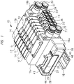
FIG. 1 is a perspective view showing a solenoid valve manifold according to one embodiment; -
FIG. 2 is a view in which (A) is a perspective view showing a wiring block and a pedestal block in a state where a connector is held at an upward position and (B) is a perspective view showing the wiring block and the pedestal block in a state where the connector is held at a lateral position; -
FIG. 3 is an exploded perspective view showing a state of separating the wiring block and the pedestal block; -
FIG. 4 is a view in which (A) is an arrow view alongline 4A-4A inFIG. 3 and (B) is a cross-sectional view taken alongline 4B-4B inFIG. 3 ; -
FIG. 5 is a view in which (A) is a cross-sectional view taken alongline 5A-5A in (A) ofFIG. 4 and (B) is a cross-sectional view taken alongline 5B-5B in (A) ofFIG. 4 ; -
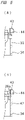
FIG. 6 is a view in which (A) is a front view of (A) ofFIG. 2 and (B) is a cross-sectional view taken alongline 6B-6B in (A); and -
FIG. 7 is a view in which (A) is a front view of (B) ofFIG. 2 and (B) is a cross-sectional view taken alongline 7B-7B in (A). - Hereinafter, embodiments of the present invention will be described in detail with reference to the drawings. A
solenoid valve manifold 10 shown inFIG. 1 has asolenoid valve aggregate 12 composed of sixsolenoid valves 11, and eachsolenoid valve 11 has amain valve block 13 and asolenoid block 14 installed on it. Themain valve block 13 is attached to amanifold block 15, and eachmanifold block 15 is installed on asupport member 16 also referred to as a DIN rail. Themain valve block 13 and thesolenoid block 14 constitute a solenoid valve, and thesolenoid valve aggregate 12 formed by aggregating the sixsolenoid valves 11 is installed on a support rail by themanifold block 15. An aggregate of themanifold blocks 15 is formed by sixmanifold blocks 15 which have the same number as the number ofsolenoid valves 11. Incidentally, the number ofsolenoid valves 11 constituting thesolenoid valve aggregate 12 inFIG. 1 is one example, and thesolenoid valve manifold 10 can be assembled by the arbitrary number ofsolenoid valves 11 as long as the number of solenoid valves is two or more. -
Piping blocks solenoid valve aggregate 12, and thepiping blocks support member 16 byend blocks supply port 21 and adischarge port 22, each of which is formed of a joint member, are provided in thepiping blocks supply port 21, and a discharge pipe is connected to thedischarge port 22. Twooutput ports manifold block 15, and each of theoutput ports - Formed in the
manifold block 15 are a supply hole and a discharge hole that are not shown. A unshown main valve shaft is incorporated in themain valve block 13. The main valve shaft switches a flow path at a position where the supply hole formed in themanifold block 15 communicates with oneoutput port 23 to supply compressed air to theoutput port 23 and a position where the supply hole communicates with theother output port 24 to supply compressed air to theoutput port 24. When the supply hole and theoutput port 23 are in communication with each other, theoutput port 24 communicates with the discharge hole. When the supply hole and theoutput port 24 are in communication with each other, theoutput port 23 communicates with the discharge hole. - Since the two
piping blocks supply ports 21 to the supply holes, but only one of the twopiping blocks - A unshown solenoid, that is, coil is incorporated in the
solenoid block 14. The compressed air is supplied from the supply hole to the main valve shaft by a drive signal supplied to the solenoid, and the main valve shaft is driven in an axial direction. In this way, thesolenoid valve 11 is of an indirect actuated type having a pilot solenoid valve. - The coil and the
connector 25 are electrically connected to each other by lead wires or a substrate that are not shown. Consequently, thesolenoid valve 11 and theconnector 25 are electrically connected to each other. When a cable connector connected to a unshown controller is installed in theconnector 25, a connection terminal of the cable connector is connected to a connection terminal provided in theconnector 25, and thesolenoid valve 11 and the controller are electrically connected via theconnector 25. - A
wiring block 26 is attached to apedestal block 27 installed on anend block 18a. Thepedestal block 27 is installed on theend block 18a and is disposed at one end portion of thesolenoid valve aggregate 12 via theend block 18a. In order to install thepedestal block 27 on theend block 18a, thepedestal block 27 is provided with an installinghole 28, and a screw member is installed in the installinghole 28. The screw member is inserted from an outer side surface of thepedestal block 27, protrudes from an inner side surface, and is screwed to theend block 18a. - The
wiring block 26 is attached to thepedestal block 27 so as to be rotatable between an upward holding position where theconnector 25 becomes an upward state and a lateral holding position where theconnector 25 becomes a lateral state. As shown inFIG. 1 , the upward position of theconnector 25 is a position where theconnector 25 protrudes from a surface opposite to a bottom surface of thesolenoid valve 11 installed on thesupport member 16. The lateral position of theconnector 25 is a position where theconnector 25 protrudes on an extension of an end portion of thesolenoid valve aggregate 12. - As described above, a member provided with the
connector 25 is thewiring block 26, and a member rotatably supporting thewiring block 26 and attached to thesolenoid valve aggregate 12 via theend block 18a and the like is thepedestal block 27. - (A) of
FIG. 2 is a perspective view showing thewiring block 26 and thepedestal block 27 in the state where theconnector 25 is held at the upward position and (B) ofFIG. 2 is a perspective view showing thewiring block 26 and thepedestal block 27 in the state where theconnector 25 is held at the lateral position.FIG. 3 is a perspective view showing a state in which thewiring block 26 and thepedestal block 27 are separated from each other. - As shown in
FIG. 2 , thepedestal block 27 has abase portion 27a extending in a longitudinal direction, and endportions FIG. 3 , anaccommodation space 29 is provided between theend portions support wall 31 is provided at theend portion 27b of thepedestal block 27, and asupport wall 31 is also provided at theother end portion 27c, as shown in (B) ofFIG. 6 and (B) ofFIG. 7 . The bothsupport walls 31 oppose each other via theaccommodation space 29. Asupport pin 32 as a fixed fitting portion is provided on eachsupport wall 31, and thesupport pin 32 protrudes from thesupport wall 31 toward theaccommodation space 29. - The
wiring block 26 has a rectangular parallelepiped shape and is shaped by a resin. Theconnector 25 attached to thewiring block 26 protrudes from aconnector arrangement face 26a of thewiring block 26. The support holes 33 into which the support pins 32 are fitted are provided as rotation fitting portions inend wall portions 34 of both ends of thewiring block 26. The support pins 32 of thepedestal block 27 are respectively fitted, that is, mated into the support holes 33, and thus thewiring block 26 is rotatably supported by thepedestal block 27. Consequently, thewiring block 26 rotates by approximately 90 degrees between the upward holding position where theconnector 25 becomes the upward state as shown in (A) ofFIG. 2 and the lateral holding position where theconnector 25 becomes the lateral state as shown in (B) ofFIG. 2 . - (A) of
FIG. 4 is an enlarged arrow view alongline 4A-4A inFIG. 3 , and (B) ofFIG. 4 is an enlarged cross-sectional view taken alongline 4B-4B inFIG. 3 . (A) ofFIG. 5 is a cross-sectional view taken alongline 5A-5A in (A) ofFIG. 4 , and (B) ofFIG. 5 is a cross-sectional view taken alongline 5B-5B in (A) ofFIG. 4 . - As shown in (B) of
FIG. 4 , an engagingclaw 30 is provided so as to protrude from the inner side surface of thepedestal block 27, and the engagingclaw 30 is engaged with an unshown engaging hole provided in theend block 18a. - As shown in
FIG. 4 , twoslits 35 are provided in the two mutually opposedsupport walls 31 of thepedestal block 27 so as to open on the inner side surface of thepedestal block 27. Anelastic deformation portion 36 is formed by a portion between theslits 35, and thesupport pin 32 serving as a fixed fitting portion is provided on theelastic deformation portion 36. A tip side of theelastic deformation portion 36 is displaced on the outer side surface of thepedestal block 27 which serves as a base end, and thus an interval between the two support pins 32 changes. - Meanwhile, support holes 33 as rotation fitting portions are provided on
end wall portions 34 of both end portions of thewiring block 26. As shown in (A) ofFIG. 5 , theend wall portion 34 provided with thesupport hole 33 is shaped continuously with theconnector arrangement face 26a, so that it is not elastically deformed. - In this way, the
support pin 32 is provided on theelastic deformation portion 36 and thesupport hole 33 is provided in theend wall portion 34, so that when thewiring block 26 is inserted into theaccommodation space 29 of thepedestal block 27, theelastic deformation portion 36 deforms and thesupport pin 32 is fitted into thesupport hole 33. This makes it possible to easily assemble thewiring block 26 to thepedestal block 27. In addition, since theelastic deformation portion 36 is not deformed in a state where thepedestal block 27 is assembled to theend block 18a, thewiring block 26 and thepedestal block 27 can be prevented from being erroneously separated. - The
support hole 33 may be provided as a fixed fitting portion in theelastic deformation portion 36 of thepedestal block 27 instead of thesupport pin 32, and thesupport pin 32 may be provided as a rotation fitting portion on theend wall portion 34 of thewiring block 26 instead of thesupport hole 33. In this way, thewiring block 26 is also rotatably supported by thepedestal block 27. - As shown in (A) of
FIG. 4 , the twoslits 37 are provided on theend wall portion 34, and slits 41 are provided outside theslits 37 along therespective slits 37. A portion between bothslits deformable leg portion 42, and twoleg portions 42 are provided on theend wall portion 34 and are separated from theconnector arrangement face 26a as shown in (B) ofFIG. 5 . Aleg portion 42 is also provided on theend wall portion 34 on an opposite side of (A) ofFIG. 4 . Theoperation part 43 is provided on tip parts of theleg portions 42 so as to couple the twoleg portions 42, and theoperation part 43 protrudes to an outside of thepedestal block 27 as shown inFIG. 2 . - Since the
operation parts 43 provided at the both end portions of thewiring block 26 are provided at the tip part of the elasticallydeformable leg portion 42 so as to protrude from theconnector arrangement face 26a of thewiring block 26, an operator can grasp 2 the twooperation parts 43 with a finger (s) . The twooperation parts 43 are displaceable in directions of approaching and separating from each other, and can be displaced in a direction of approaching each other with the finger, so that when the finger is separated from theoperation parts 43, theoperation parts 43 are displaced in a direction of separating from each other. - An engaging
convex part 44 as an operation engaging part is provided on theoperation part 43. As shown in (A) ofFIG. 4 , the engagingconvex part 44 protrudes from abottom surface 43a of theoperation part 43 in a bottom surface direction of thewiring block 26 and, as shown in (A) ofFIG. 5 , protrudes further longitudinally outward to thewiring block 26 than theend wall portion 34. The engagingconvex part 44 has a firstconvex part 44a and a secondconvex part 44b. The firstconvex part 44a protrudes from theoperation part 43 in the bottom surface direction of thewiring block 26. The secondconvex part 44b protrudes from abottom surface 44c of the firstconvex part 44a in the bottom surface direction of thewiring block 26. A width of the firstconvex part 44a is larger than that of the secondconvex part 44b. Meanwhile, as an upward engaging part to be engaged with, that is, caught at the engagingconvex part 44, engagingconcave parts 45 are provided at upper end portions of both thesupport wall 31 of thepedestal block 27 by notching thesupport wall 31 and the upper surface of thepedestal block 27. Further, as a lateral engaging part to be engaged with the engagingconvex part 44, an engagingconcave part 46 is provided on an outer side surface of thesupport wall 31 by notching thesupport wall 31 and the outer side surface of thepedestal block 27. - If it is assumed that: D1 is a distance from a center of the
support hole 33, that is, a rotation axis to thebottom surface 43a of theoperation part 43; D2 is a distance from the center of thesupport hole 33 to thebottom surface 44c of the firstconvex part 44a; L1 is a distance from a center of thesupport pin 32 to an upper surface on which the first engagingconcave part 45 opens; and L2 is a distance from the center of thesupport pin 32 to the outer side surface on which the first engaging concave part opens, L2 < D2 < L1 < D1 is satisfied. As a result, as shown inFIG. 6 , the first engagingconcave part 45 as an upward engaging part is engaged with the firstconvex part 44a when theconnector 25 is held at the upward position. As shown inFIG. 7 , the second engagingconcave part 46 as a lateral engaging part is engaged with the secondconvex part 44b when theconnector 25 is held at the lateral position. - When a posture is switched from a state where the
connector 25 becomes an upward posture and thewiring block 26 is held by thepedestal block 27 as shown in (A) ofFIG. 2 and (A) ofFIG. 6 to a state where theconnector 25 becomes a lateral posture and thewiring block 26 is held by thepedestal block 27 as shown in (B) ofFIG. 2 andFIG. 7 , the operator grips the twooperation parts 43 with one hand and displaces theoperation parts 43 in a direction in which they approach each other. Consequently, the firstconvex part 44a is separate from the engagingconcave part 45, and thewiring block 26 becomes a state of being able to rotate about thesupport pin 32. Under this state, thewiring block 26 can be rotated from the upward posture to the lateral posture while theoperation parts 43 are grasped. - When the finger holding the
operation parts 43 is released from theoperation parts 43 under a state where thewiring block 26 is rotated to the lateral posture, the secondconvex part 44b is engaged with the engagingconcave part 46 as a lateral engaging part by an elastic force of theleg portion 42. Consequently, thewiring block 26 is held at the lateral posture. Meanwhile, even when thewiring block 26 is switched from the lateral posture to the upward posture, theoperation parts 43 are gripped by the finger of one hand and theoperation parts 43 are displaced in the direction of approaching each other. Consequently, the engagement of the secondconvex part 44b and the engagingconcave part 46 is released. Next, the posture can be changed by rotating thewiring block 26 while theoperation parts 43 are grasped. - In this way, in the above-mentioned
solenoid valve manifold 10, the operator can perform the engagement with and the disengagement from the operation engaging part and the rotation of the wiring block while holding the twooperation parts 43 with the finger(s), and the operability of the posture switching operation of theconnector 25 can be improved. - The engaging convex part may be provided as a connector engaging part instead of the engaging
convex part 44 provided at the tip part of theleg portion 42 of thewiring block 26, and the engagingconcave parts support wall 31 of thepedestal block 27 may be respectively used as an upward engaging part and a lateral engaging part that serve as the engaging convex parts. Also in this way, thewiring block 26 is held in both the upward posture and the lateral posture. - The present invention is not limited to the above-mentioned embodiments, and can variously be modified without a range not departing from the scope of the present invention. For example, the solenoid valve manifold according to one embodiment is a separate type in which the manifold block is installed on each solenoid valve, and the manifold blocks also become an aggregate. However, the above-mentioned wiring blocks can be applied also to such an integrated type of solenoid valve manifold that the plurality of solenoid valves are mounted on a single manifold block. In addition, the mounted solenoid valve can also be a directly actuated type.
- The solenoid valve manifold is used, in the technical field of using a pneumatic actuated device, to control the supply of compressed air to the pneumatic actuated device.
Claims (9)
- A solenoid valve manifold including a solenoid valve aggregate formed by aggregating a plurality of solenoid valves, the solenoid valve manifold comprising:a wiring block including a connector electrically connected to the solenoid valves;a pedestal block disposed on the solenoid valve aggregate, an accommodation space in which the wiring block is accommodated being formed in the pedestal block;fixed fitting parts provided on a support wall of the pedestal block so as to oppose each other via the accommodation space;rotation fitting parts provided on end wall portions of both ends of the wiring block, and rotatably supporting the wiring block between an upper holding position and a lateral holding position where the rotation fitting parts are fitted into the fixed fitting parts and the connector becomes an upper state and a lateral state, respectively;operation parts provided on tip parts of elastically deformable leg portions provided on end wall portions of both ends of the wiring block, the operation parts being displaceable in directions of approaching and separating from each other;an operation engaging part provided on the operation parts; andan upward engaging part provided on the pedestal block and engaged with the operation engaging part when the connector is held at the upward position, and a lateral engaging part engaged with the operation engaging part when the connector is held at the lateral position,wherein engagement with and disengagement from the operation engaging part and rotation of the wiring block are able to be performed by making the operation parts approach each other.
- The solenoid valve manifold according to claim 1,
wherein each of the fixed fitting parts is a support pin protruding from the support wall, and the rotation fitting part is a support hole into which the support pin is fitted. - The solenoid valve manifold according to claim 1 or 2,
wherein the upward engaging part and the lateral engaging part are each an engaging concave part, and the operation engaging part is an engaging convex part engaged with the engaging concave part. - The solenoid valve manifold according to claim 3,wherein the engaging convex part has a first convex part protruding from a bottom surface of the operation part in a bottom surface direction of the wiring block, and a second convex part protruding from a bottom surface of the first convex part in the bottom surface direction of the wiring block, andthe engaging concave part has a first engaging concave part formed by notching an upper surface of the pedestal block and the support wall, and a second engaging concave part formed by notching an outer side surface of the pedestal block and the support wall.
- The solenoid valve manifold according to claim 4,
wherein a width of the first convex part is larger than a width of the second convex part. - The solenoid valve manifold according to claim 4,
wherein if it is assumed that a distance from a rotation axis to the bottom surface of each of the operation parts is D1, a distance from the rotation axis to the bottom surface of the first convex part is D2, a distance from the rotation axis to an upper surface in which the first engaging concave part opens is L1, and a distance from the rotation axis to an outer side surface in which the first engaging concave part opens is L2, L2 < D2 < L1 < D1 is satisfied. - The solenoid valve manifold according to any one of claims 1 to 6,wherein the wiring block has a connector arrangement face from which the connector protrudes,a gap is formed between the leg portion and the connector arrangement face, andthe end wall portion is formed to be continuous with the connector arrangement face.
- The solenoid valve manifold according to any one of claims 1 to 3,wherein each of the fixed fitting parts is provided in an elastic deformation portion provided on the support wall, andeach of the rotation fitting parts is provided on the end wall portion so as to be capable of fitting the fixed fitting parts and the rotation fitting parts by elastically deforming the elastic deformation portion when the wiring block is attached to the pedestal block.
- The solenoid valve manifold according to any one of claims 1 to 4,wherein each of the solenoid valves includes:a main valve block provided with a main valve shaft for switching a flow path; andsolenoid blocks installed on the main valve block,the solenoid valves are attached to the manifold blocks each provided with an output port, andan aggregate of the manifold blocks is installed on a support member.
Applications Claiming Priority (2)
| Application Number | Priority Date | Filing Date | Title |
|---|---|---|---|
| JP2020071509 | 2020-04-13 | ||
| PCT/JP2021/014009 WO2021210407A1 (en) | 2020-04-13 | 2021-03-31 | Solenoid valve manifold |
Publications (2)
| Publication Number | Publication Date |
|---|---|
| EP4137724A1 true EP4137724A1 (en) | 2023-02-22 |
| EP4137724A4 EP4137724A4 (en) | 2024-04-17 |
Family
ID=78084202
Family Applications (1)
| Application Number | Title | Priority Date | Filing Date |
|---|---|---|---|
| EP21788843.7A Pending EP4137724A4 (en) | 2020-04-13 | 2021-03-31 | Solenoid valve manifold |
Country Status (5)
| Country | Link |
|---|---|
| EP (1) | EP4137724A4 (en) |
| JP (1) | JPWO2021210407A1 (en) |
| KR (1) | KR20220164505A (en) |
| CN (1) | CN115335624A (en) |
| WO (1) | WO2021210407A1 (en) |
Family Cites Families (5)
| Publication number | Priority date | Publication date | Assignee | Title |
|---|---|---|---|---|
| JPH09133240A (en) * | 1995-11-06 | 1997-05-20 | Smc Corp | Feeder for solenoid valve assembly |
| JP3456928B2 (en) * | 1999-10-18 | 2003-10-14 | Smc株式会社 | Power supply device for solenoid valve assembly |
| JP4074121B2 (en) | 2002-04-10 | 2008-04-09 | シーケーディ株式会社 | Solenoid valve manifold |
| JP6035286B2 (en) * | 2014-06-11 | 2016-11-30 | Ckd株式会社 | Solenoid valve manifold |
| JP6145442B2 (en) | 2014-11-21 | 2017-06-14 | Ckd株式会社 | Solenoid valve manifold |
-
2021
- 2021-03-31 JP JP2022515299A patent/JPWO2021210407A1/ja active Pending
- 2021-03-31 EP EP21788843.7A patent/EP4137724A4/en active Pending
- 2021-03-31 CN CN202180022800.1A patent/CN115335624A/en active Pending
- 2021-03-31 WO PCT/JP2021/014009 patent/WO2021210407A1/en unknown
- 2021-03-31 KR KR1020227034794A patent/KR20220164505A/en unknown
Also Published As
| Publication number | Publication date |
|---|---|
| CN115335624A (en) | 2022-11-11 |
| WO2021210407A1 (en) | 2021-10-21 |
| EP4137724A4 (en) | 2024-04-17 |
| JPWO2021210407A1 (en) | 2021-10-21 |
| KR20220164505A (en) | 2022-12-13 |
| US20230151901A1 (en) | 2023-05-18 |
Similar Documents
| Publication | Publication Date | Title |
|---|---|---|
| CN102037612B (en) | Push-type connector | |
| US8317532B2 (en) | Connector and connecting unit | |
| EP1956686B1 (en) | Connector with an elastic slider | |
| US7397668B2 (en) | Signal input/output device | |
| US6783385B2 (en) | Electrical connector for securing a wire to a contact | |
| US6254408B1 (en) | Plug-in connection structure | |
| US8735754B2 (en) | Power transfer switch | |
| EP3389140A1 (en) | Electrical connector | |
| EP1320150A3 (en) | Electrical connector assembly for connecting electrical contacts | |
| US7419401B2 (en) | Terminal contact for electric conductors | |
| EP4137724A1 (en) | Solenoid valve manifold | |
| US7544080B2 (en) | Electrical plug connector coupling | |
| US11994225B2 (en) | Solenoid valve manifold | |
| US8342866B2 (en) | Connector assemblies having mating sides moved by fluidic coupling mechanisms | |
| US11621514B2 (en) | Electrical connector with connector housing joined by a flexible joining member | |
| US6840805B2 (en) | Plug-and-socket connector element | |
| CN106663896B (en) | Connector with latch | |
| CN107799987B (en) | Electrical connection device and dual switching system comprising two such devices | |
| US6720510B2 (en) | Pusher assembly and method of assembling a pusher assembly | |
| EP1024560B1 (en) | Two-part electrical connector | |
| USRE39958E1 (en) | Plug-and-socket connector element | |
| CN211555802U (en) | Auxiliary contact device | |
| US7211757B2 (en) | Push slide switch | |
| US6035529A (en) | Header pin pre-loaded method | |
| JP2696308B2 (en) | No insertion force connector |
Legal Events
| Date | Code | Title | Description |
|---|---|---|---|
| STAA | Information on the status of an ep patent application or granted ep patent |
Free format text: STATUS: THE INTERNATIONAL PUBLICATION HAS BEEN MADE |
|
| PUAI | Public reference made under article 153(3) epc to a published international application that has entered the european phase |
Free format text: ORIGINAL CODE: 0009012 |
|
| STAA | Information on the status of an ep patent application or granted ep patent |
Free format text: STATUS: REQUEST FOR EXAMINATION WAS MADE |
|
| 17P | Request for examination filed |
Effective date: 20221012 |
|
| AK | Designated contracting states |
Kind code of ref document: A1 Designated state(s): AL AT BE BG CH CY CZ DE DK EE ES FI FR GB GR HR HU IE IS IT LI LT LU LV MC MK MT NL NO PL PT RO RS SE SI SK SM TR |
|
| DAV | Request for validation of the european patent (deleted) | ||
| DAX | Request for extension of the european patent (deleted) | ||
| A4 | Supplementary search report drawn up and despatched |
Effective date: 20240318 |
|
| RIC1 | Information provided on ipc code assigned before grant |
Ipc: F15B 13/08 20060101ALI20240312BHEP Ipc: F16K 27/02 20060101ALI20240312BHEP Ipc: F16K 31/06 20060101ALI20240312BHEP Ipc: F16K 27/00 20060101AFI20240312BHEP |