EP4137674B1 - Verformbarer stossfänger für eine rotierende struktur eines turbomotors - Google Patents
Verformbarer stossfänger für eine rotierende struktur eines turbomotors Download PDFInfo
- Publication number
- EP4137674B1 EP4137674B1 EP22191265.2A EP22191265A EP4137674B1 EP 4137674 B1 EP4137674 B1 EP 4137674B1 EP 22191265 A EP22191265 A EP 22191265A EP 4137674 B1 EP4137674 B1 EP 4137674B1
- Authority
- EP
- European Patent Office
- Prior art keywords
- bumper
- crushable
- bearing support
- section
- assembly
- Prior art date
- Legal status (The legal status is an assumption and is not a legal conclusion. Google has not performed a legal analysis and makes no representation as to the accuracy of the status listed.)
- Active
Links
Images


Classifications
-
- F—MECHANICAL ENGINEERING; LIGHTING; HEATING; WEAPONS; BLASTING
- F01—MACHINES OR ENGINES IN GENERAL; ENGINE PLANTS IN GENERAL; STEAM ENGINES
- F01D—NON-POSITIVE DISPLACEMENT MACHINES OR ENGINES, e.g. STEAM TURBINES
- F01D21/00—Shutting-down of machines or engines, e.g. in emergency; Regulating, controlling, or safety means not otherwise provided for
- F01D21/04—Shutting-down of machines or engines, e.g. in emergency; Regulating, controlling, or safety means not otherwise provided for responsive to undesired position of rotor relative to stator or to breaking-off of a part of the rotor, e.g. indicating such position
- F01D21/045—Shutting-down of machines or engines, e.g. in emergency; Regulating, controlling, or safety means not otherwise provided for responsive to undesired position of rotor relative to stator or to breaking-off of a part of the rotor, e.g. indicating such position special arrangements in stators or in rotors dealing with breaking-off of part of rotor
-
- F—MECHANICAL ENGINEERING; LIGHTING; HEATING; WEAPONS; BLASTING
- F01—MACHINES OR ENGINES IN GENERAL; ENGINE PLANTS IN GENERAL; STEAM ENGINES
- F01D—NON-POSITIVE DISPLACEMENT MACHINES OR ENGINES, e.g. STEAM TURBINES
- F01D25/00—Component parts, details, or accessories, not provided for in, or of interest apart from, other groups
- F01D25/04—Antivibration arrangements
-
- F—MECHANICAL ENGINEERING; LIGHTING; HEATING; WEAPONS; BLASTING
- F01—MACHINES OR ENGINES IN GENERAL; ENGINE PLANTS IN GENERAL; STEAM ENGINES
- F01D—NON-POSITIVE DISPLACEMENT MACHINES OR ENGINES, e.g. STEAM TURBINES
- F01D25/00—Component parts, details, or accessories, not provided for in, or of interest apart from, other groups
- F01D25/16—Arrangement of bearings; Supporting or mounting bearings in casings
- F01D25/162—Bearing supports
- F01D25/164—Flexible supports; Vibration damping means associated with the bearing
-
- F—MECHANICAL ENGINEERING; LIGHTING; HEATING; WEAPONS; BLASTING
- F05—INDEXING SCHEMES RELATING TO ENGINES OR PUMPS IN VARIOUS SUBCLASSES OF CLASSES F01-F04
- F05D—INDEXING SCHEME FOR ASPECTS RELATING TO NON-POSITIVE-DISPLACEMENT MACHINES OR ENGINES, GAS-TURBINES OR JET-PROPULSION PLANTS
- F05D2250/00—Geometry
- F05D2250/20—Three-dimensional
- F05D2250/28—Three-dimensional patterned
- F05D2250/283—Three-dimensional patterned honeycomb
-
- F—MECHANICAL ENGINEERING; LIGHTING; HEATING; WEAPONS; BLASTING
- F05—INDEXING SCHEMES RELATING TO ENGINES OR PUMPS IN VARIOUS SUBCLASSES OF CLASSES F01-F04
- F05D—INDEXING SCHEME FOR ASPECTS RELATING TO NON-POSITIVE-DISPLACEMENT MACHINES OR ENGINES, GAS-TURBINES OR JET-PROPULSION PLANTS
- F05D2260/00—Function
- F05D2260/96—Preventing, counteracting or reducing vibration or noise
Definitions
- This disclosure relates generally to a turbine engine and, more particularly, to a bearing support for a turbine engine.
- a gas turbine engine includes a stationary structure and a rotating structure rotatably mounted with the stationary structure via a plurality of bearings. Under certain conditions, one or more portions of the rotating structure may vibrate, wobble and/or otherwise shift relative to the stationary structure.
- Various devices and systems are known in the art for accommodating and/or controlling such shifting between the rotating structure and the stationary structure. While these known devices and systems have various benefits, there is still room in the art for improvement.
- US 2016/097301 A1 discloses a prior art assembly for a turbine engine comprising a bearing support arrangement with a shock-absorbing element provided in parallel to a predetermined breaking point formed in the area of the fan bearing.
- the flexible bearing support may also be configured to crush the crushable bumper during the second mode of operation.
- the flexible bearing support may also be configured to permanently deform the crushable bumper during the second mode of operation.
- a first portion of the crushable bumper may be configured to crush when subject to a first load.
- a second portion of the crushable bumper may be configured to crush when subject to a second load that is different than the first load.
- the first load may be greater than the second load.
- the second portion of the crushable bumper may be arranged radially between the first portion of the crushable bumper and the flexible bearing support.
- the first portion of the crushable bumper may have a first porosity.
- the second portion of the crushable bumper may have a second porosity that is different than the first porosity.
- the first portion of the crushable bumper may include an empty cavity.
- the second portion of the crushable bumper may include a cavity at least partially filled with filler material.
- the crushable bumper may be configured from or otherwise include foam.
- the crushable bumper may be configured from or otherwise include a lattice structure.
- the stationary structure may also include a fixed support.
- the crushable bumper may be mounted to the fixed support.
- a radial outer side of the fixed support may be configured to form a peripheral boundary of a flowpath within the turbine engine.
- the flexible bearing support may include a mount section, a bearing support section and a spring section axially between and connected to the mount section and the bearing support section.
- the bearing may be mounted to the bearing support section.
- the spring section may include a plurality of slots arranged circumferentially about a rotational axis of the rotating structure. Each of the slots may extend radially through the spring section.
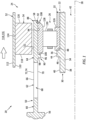
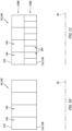
- FIG. 1 illustrates an assembly 20 for a turbine engine.
- This turbine engine assembly 20 includes a rotating structure 22, a stationary structure 24 and at least one bearing 26 rotatably mounting the rotating structure 22 with the stationary structure 24.
- the rotating structure 22 extends axially along and is rotatable about a rotational axis 28, which rotational axis 28 may be coaxial with an axial centerline of the turbine engine assembly 20.
- the rotating structure 22 of FIG. 1 includes a shaft 30 and a second component 32.
- Examples of the second component 32 of the rotating structure 22 include, but are not limited to, a sleeve, a spacer, a baffle, another shaft, a coupling, a seal land and a retainer (e.g., a clip, a nut, etc.).
- the shaft 30 of FIG. 1 includes a (e.g., tubular) shaft base 34 and a (e.g., annular) shaft shoulder 36.
- the shaft base 34 extends axially along and circumferentially about (e.g., completely around) the rotational axis 28.
- the shaft base 34 extends radially between and to an inner side 38 of the shaft 30 and an outer side 40 of the shaft base 34.
- the shaft inner side 38 of FIG. 1 forms an internal bore 42 within the shaft 30, which internal bore 42 extends axially within (e.g., and into, or through) the shaft 30 and its shaft base 34.
- the stationary structure 24 of FIG. 1 includes a bearing support 50, a fixed support 52 and a bumper 54.
- the bearing support 50 of FIG. 1 is cantilevered from another portion 56 of the stationary structure 24.
- the bearing support 50 projects axially along the rotational axis 28 out from the stationary structure portion 56 to a distal (e.g., unsupported) end 58 of the bearing support 50.
- the bearing support 50 extends circumferentially about (e.g., completely around) the rotational axis 28, thereby providing the bearing support 50 with a tubular body.
- the bearing support 50 may be configured as a flexible bearing support.
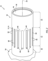
- the bearing support 50 of FIG. 2 for example, includes a mount section 60, an intermediate (e.g., spring) section 62 and a bearing support section 64.
- the mount section 60 extends axially along the rotational axis 28 between and to the stationary structure portion 56 and the intermediate section 62.
- the mount section 60 is connected to (e.g., formed integral with or otherwise attached to) the stationary structure portion 56 and the intermediate section 62.
- the mount section 60 thereby connects and structurally ties the bearing support 50 to the stationary structure portion 56.
- the mount section 60 of FIG. 2 extends circumferentially about (e.g., completely around) the rotational axis 28, and may be circumferentially and/or axially uninterrupted.
- the intermediate section 62 extends axially along the rotational axis 28 between and to the mount section 60 and the support section 64.
- the intermediate section 62 is connected to (e.g., formed integral with or otherwise attached to) the mount section 60 and the support section 64.
- the intermediate section 62 thereby connects and structurally ties the support section 64 to the mount section 60.
- the intermediate section 62 may provide the only structural support for the support section 64 given, for example, the cantilevered connection of the bearing support 50 to the stationary structure portion 56.
- the intermediate section 62 of FIG. 2 includes a plurality of beams 66 and/or a plurality of slots 68.
- the beams 66 and the slots 68 are distributed circumferentially about the rotational axis 28.
- the beams 66 are interspersed with the slots 68 such that: (A) each of the beams 66 is disposed and extends laterally (e.g., circumferentially or tangentially) between a respective lateral neighboring (e.g., adjacent) pair of the slots 68; and (B) each of the slots 68 is disposed and extends laterally within the intermediate section 62 between a respective laterally neighboring pair of the beams 66.
- Each of the beams 66 extends axially along the rotational axis 28 between and is connected to the mount section 60 and the support section 64.
- Each of the slots 68 extends axially along the rotational axis 28 within the bearing support 50 (and through the intermediate section 62) between and to the mount section 60 and the support section 64. Referring to FIG. 1 , each of the slots 68 extends (e.g., completely) radially through the bearing support 50 and its intermediate section 62 between and to an inner side 70 of the intermediate section 62 and an outer side 72 of the intermediate section 62, which may also be an outer side 74 of the bearing support 50.
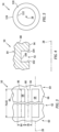
- each of the beams 66 has a longitudinal length 76 and a lateral width 78.
- the beam longitudinal length 76 is measured along a longitudinal centerline 80 of the respective beam 66 from the mount section 60 to the support section 64.
- Each beam longitudinal centerline 80 of FIG. 3 is straight and parallel with the rotational axis 28; however, the present disclosure is not limited to such an exemplary configuration.
- the beam lateral width 78 is measured between opposing lateral sides of the respective beam 66; e.g., between the respective laterally neighboring pair of the slots 68.
- Each of the slots 68 has a longitudinal length 82 and a lateral width 84, where the slot longitudinal length 82 is equal to the beam longitudinal length 76 and the slot lateral width 84 may be equal to or different (e.g., greater or less) than the beam lateral width 78.
- the slot longitudinal length 82 is measured along a longitudinal centerline 86 of the respective slot 68 from the mount section 60 to the support section 64.
- Each slot longitudinal centerline 86 of FIG. 3 is straight and parallel with the rotational axis 28; however, the present disclosure is not limited to such an exemplary configuration.
- the slot lateral width 84 is measured between opposing lateral sides of the respective slot 68; e.g., between the respective laterally neighboring pair of the beams 66.
- the dimensions (e.g., 76, 78, 82, 84) of the beams 66 and the slots 68 are selected to tune the intermediate section 62 to provide the bearing support 50 with a certain amount of flexibility.
- the intermediate section 62 and its beams 66 may be configured to facilitate a certain degree of twist between the support section 64 and the mount section 60 about the rotational axis 28.
- the intermediate section 62 and its beams 66 may also or alternatively be configured to facilitate a certain degree of radial displacement between the support section 64 and the mount section 60.
- the intermediate section 62 may thereby accommodate slight shifts between and/or vibrations in the rotating structure 22 and the stationary structure 24.
- the support section 64 of FIG. 2 extends axially along the rotational axis 28 between and to the intermediate section 62 and the support distal end 58.
- the support section 64 of FIG. 2 extends circumferentially about (e.g., completely around) the rotational axis 28, and may be circumferentially and/or axially uninterrupted.
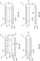
- the support section 64 of FIG. 1 includes a support section base 88, a support section shoulder 90 and a support section slot 92.
- the section base 88 extends axially along and circumferentially about (e.g., completely around) the rotational axis 28.
- the section base 88 extends radially between and to an inner side 94 of the section base 88 (e.g., the intermediate section inner side 70) and the support outer side 74.
- the section shoulder 90 is connected to the section base 88 at the base inner side 94.
- the section shoulder 90 of FIG. 1 projects radially inward from the section base 88 and its base inner side 94 to a distal end 96 of the section shoulder 90.
- the section shoulder 90 of FIG. 1 extends axially along the rotational axis 28 between and to a first side 98 of the section shoulder 90 and a second side 100 of the section shoulder 90.
- the section shoulder 90 may extend circumferentially about (e.g., completely around) the rotational axis 28.
- the section slot 92 is arranged at (e.g., on, adjacent or proximate) the support distal end 58.
- the section slot 92 extends circumferentially about (e.g., completely around) the rotational axis 28 within the section base 88. Referring to FIG. 4 , the section slot 92 extends axially along the rotational axis 28 within the section base 88 between and to opposing sides 102 and 104 of the section slot 92.
- the section slot 92 projects radially into the section base 88 from the support inner side 94 to an end 106 of the section slot 92.
- the section slot 92 may be configured as a receptacle for an annular retainer 108 (e.g., a split ring).
- the fixed support 52 may be structurally tied to the stationary structure portion 56.
- the fixed support 52 of FIG. 1 extends axially along the rotational axis 28.
- the fixed support 52 extends circumferentially about (e.g., completely around) the rotational axis 28.
- the fixed support 52 projects radially inward (e.g., towards the rotational axis 28) to an inner side 110 of the fixed support 52.
- the fixed support 52 may project radially outwards (e.g., away from the rotational axis 28) to an outer side 112 of the fixed support 52.
- This fixed support outer side 112 may form a (e.g., inner) peripheral boundary of a volume 114 outside of a bearing compartment 116 housing the bearing 26, which volume 114 may be a flowpath 116 within the turbine engine.
- the bumper 54 extends axially along the rotational axis 28 between and to opposing ends 118 and 120 of the bumper 54. Referring to FIG. 5 , the bumper 54 extends circumferentially about (e.g., completely around) the rotational axis 28, thereby providing the bumper 54 with a full hoop body.
- the bumper 54 of FIGS. 1 and 5 is circumferentially and/or axially uninterrupted, and may be forms as a single unitary (e.g., monolithic) body.
- the bumper 54 of FIG. 1 extends radially between and to an inner side 122 of the bumper 54 and an outer side 124 of the bumper 54.
- the bumper 54 is configured as a (e.g., permanently) deformable body. More particularly, the bumper 54 may be configured as a (e.g., radially) crushable body. The bumper 54 may have various configurations to tune its deformation (e.g., crushability), various examples of which are described below with reference to FIGS. 7A-13 . The present disclosure, however, is not limited to such exemplary bumper configurations.
- the bumper outer side 124 of FIG. 1 may be abutted against and/or otherwise radially engage (e.g., contact) the fixed support 52 and its inner side 110.
- the bumper 54 is also mounted to the fixed support 52.
- the bumper 54 for example, may be fixedly secured to the fixed support 52 through a mechanical coupling (e.g., via interference fit, mechanical fastener, etc.), a bond (e.g., weld, braze, adhesive, etc.) joint and/or any other attachment technique.
- the bumper 54 of FIG. 1 is radially outboard of and extends circumferentially about (e.g., completely around) each of the turbine engine assembly elements 22, 26, 30, 50 and 64.
- the bumper 54 is axially aligned with the bearing support 50 and its support section 64.
- the bumper 54 of FIG. 1 for example, axially overlaps the support section 64 at (or near) the support distal end 58.
- the bearing 26 may be configured as a roller element bearing.
- the bearing 26 of FIG. 1 for example, includes a (e.g., tubular) inner race 126, a (e.g., tubular) outer race 128 and a plurality of bearing elements 130. These bearing elements 130 are arranged circumferentially about the rotational axis 28 in an annular array. The bearing elements 130 are located radially between and radially engaged with the inner race 126 and the outer race 128.
- the inner race 126 is mounted to the rotating structure 22.
- the inner race 126 of FIG. 1 for example, circumscribes and radially engages (e.g., contacts) the shaft base 34 and a surface thereof at its outer side 40.
- the inner race 126 is axially captured and clamped between the shaft shoulder 36 and the second component 32 of the rotating structure 22.
- the inner race 126 may thereby be fixed to and rotatable with the rotating structure 22.
- the outer race 128 is mounted to the stationary structure 24 and, more particularly, to the support section 64 at (e.g., on, adjacent or proximate) the support distal end 58.
- the outer race 128 of FIG. 1 for example, is arranged within a bore of the bearing support 50 and its support section 64, which support section 64 circumscribes and radially engages (e.g., contacts) the outer race 128 and an outer surface thereof.
- the outer race 128 is axially captured and clamped between the section shoulder 90 and the retainer 108.
- the outer race 128 may also or alternatively be mechanically fixed (e.g., press fit) into the bore of the support section 64. The outer race 128 may thereby be fixed to the stationary structure 24 and its bearing support 50.
- the bumper 54 is radially displaced from the bearing support 50 and its support section 64 by an (e.g., annular) air gap 132.
- This air gap 132 has a height 134 with a first value.
- This gap height 134 extends radially between and to an (e.g., cylindrical) outer surface 136 of the support section 64 at the support outer side 74 and an (e.g., cylindrical) inner surface 138 of the bumper 54 at the bumper inner side 122.
- the air gap 132 extends axially along the surfaces 136 and 138 for a (e.g., entire) length 140 of the bumper 54, which bumper length 140 extends between and to the bumper sides 118 and 120.
- the air gap 132 extends circumferentially about (e.g., completely around) the rotational axis 28, thereby forming the air gap 132 as an annulus which circumscribes the support section 64.
- the bumper 54 is (e.g., completely) structurally disengaged from (e.g., does not contact and/or structurally support) the bearing support 50 and its support section 64.
- the bumper 54 also has a height 142 with a first value. This bumper height 142 extends radially between and to the bumper inner side 122 and the bumper outer side 124.
- a first (e.g., shock and/or imbalance) load may radially displace the rotating structure 22 (see FIG. 1 ).
- This first load is equal to or greater than a first threshold, but less than a second threshold.
- the first load may be generated during and/or follow from an off-nominal operating condition and/or event such as, but not limited to, a partial blade off event and/or a relatively large rotating structure imbalance.
- the radial displacement of the rotating structure 22 displaces the bearing 26 and the bearing support 50 radially outward.
- the support section 64 and its outer surface 136 may thereby temporarily radially engage (e.g., contact) the bumper 54 and its inner surface 138.
- the bumper 54 provides a radial stop (e.g., a bump stop) for the rotating structure radial displacement. While the bumper 54 may slightly deform upon initial engagement (e.g., impact) between the surfaces 136 and 138, this deformation may be elastic / resilient. Thus, the bumper height 142 may have a second value that is substantially (e.g., +/-2%) or exactly equal to the bumper height first value. A configuration of the bumper 54 may thereby remain substantially unchanged between the mode of nominal turbine engine operation and the first mode of off-nominal turbine engine operation.
- a radial stop e.g., a bump stop
- a second (e.g., shock and/or imbalance) load may radially displace the rotating structure 22 (see FIG. 1 ).
- This second load is equal to or greater than the second threshold.
- the second load may be generated during and/or follow from an off-nominal operating condition and/or event such as, but not limited to, a full blade off event.
- the radial displacement of the rotating structure 22 displaces the bearing 26 and the bearing support 50 radially outward.
- the support section 64 and its outer surface 136 may thereby temporarily radially engage (e.g., contact) the bumper 54 and its inner surface 138.
- the bumper 54 again provides a radial stop for the rotating structure radial displacement.
- the bumper 54 may also provide a damper (e.g., a shock absorber) for the displaced rotating structure 22.
- a damper e.g., a shock absorber
- the bumper 54 may (e.g., permanently) deform radially outward.
- the crushing may also tune a response of the rotating structure 22, for example, by changing rotor-dynamic modes.
- the bumper height 142 has a third value that is less than the bumper height first and second values.
- the bumper height third value may be less than four-fifths (4/5), two-thirds (2/3), one-half (1/2), one-third (1/3) or otherwise of the bumper height first value.
- the present disclosure is not limited to the foregoing exemplary dimensional relationship.
- the bumper 54 may remain substantially or completely deformed.
- the bumper height 142 may have a fourth value that is substantially (e.g., +/-2%) or exactly equal to the bumper height third value.
- the gap height 134 has a second value that is greater than the gap height first value (see FIG. 6A ) prior to the deformation (e.g., crushing) of the bumper 54.
- the bumper 54 is configured with a porous body.
- the bumper 54 of FIGS. 7A-9 includes a plurality of internal cavities 144 (e.g., pores, chambers, interstices), which cavities 144 provide space for the bumper 54 to deform; e.g., crush.
- One or more of the cavities 144 may be configured as separate, fluidly discrete cavities.
- One or more of the cavities 144 may also or alternatively be fluidly coupled with another one or more of the cavities 144; e.g., the cavities 144 may be interconnected to provide a volume.
- the bumper 54 is constructed from a bumper material such as, but not limited to, a metal, a polymer, a composite material or a combination thereof.
- the bumper 54 may be configured with or otherwise include honeycomb 146; e.g., a honeycomb body.
- honeycomb 146 e.g., a honeycomb body.
- Each cavity 144 of FIG. 7A is configured with a polygonal (e.g., hexagonal) cross-sectional geometry when viewed, for example, in a plane perpendicular to a centerline 148 of the respective cavity 144.
- the cavity centerline 148 may be arranged perpendicular to the bumper inner surface 138 / the bumper inner side 122.
- Each cavity 144 of FIG. 7B may extends longitudinally along its cavity centerline 148 between and to (or about) the bumper inner side 122 and the bumper outer side 124.
- the bumper 54 may be configured with or otherwise include foam; e.g., a foam body.
- the foam may be configured as open cell foam 150 where its internal cavities 144 (e.g., pores) are interconnected.
- the foam may alternatively be configured as closed cell foam 152 where its internal cavities 144 are discrete.
- the bumper 54 may be configured with or otherwise include a lattice structure 154; e.g., a lattice structure body.
- This lattice structure 154 may include one or more repeated cells, where each cell may include a plurality (e.g., a pattern) of interconnected elements 156; e.g., columns.
- the structure / configuration of the bumper 54 may be uniform axially across an axial length of the bumper 54 between and to the bumper ends 118 and 120 (see FIG. 1 ).
- the structure / configuration of the bumper 54 may be uniform circumferentially about (e.g., completely around) the rotational axis 28.
- the structure / configuration of the bumper 54 may also be uniform radially across the (e.g., radial) height 142 (see FIG. 6A ) of the bumper 54 between and to the bumper sides 122 and 124.
- Such an arrangement may provide the bumper 54 with a uniform damping characteristic.
- the structure / configuration of the bumper 54 may be non-uniform to tailor the bumper 54 with a progressive stiffness characteristic and/or a progressive damping characteristic.
- an inner portion 158A (e.g., radial zone) of the bumper 54 may be configured with a different stiffness characteristic and/or a different damping characteristic than an outer portion 158B (e.g., radial zone) of the bumper 54.
- the bumper inner portion 158A is configured to deform (e.g., crush) when subject to an inner portion load.
- the bumper outer portion 158B is configured to deform (e.g., crush) when subject to an outer portion load, where the outer portion load is different (e.g., greater or less) than the inner portion load.
- the bumper inner portion 158A for example, may be configured with an inner portion porosity and an inner portion density.
- the bumper outer portion 158B may be configured with an outer portion porosity and an outer portion density, where the outer portion porosity is different (e.g., greater or less) than the inner portion porosity and the outer portion density is different (e.g., less or greater) than the inner portion density.
- the bumper inner portion 158A may be provided with an inner portion number of the internal cavities 144, where each of those internal cavities 144 has an inner portion dimension (e.g., diameter, length, etc.).
- the bumper outer portion 158B may be provided with an outer portion number of the internal cavities 144, where each of those internal cavities 144 has an outer portion dimension (e.g., diameter, length, etc.).
- the inner portion number may be different (e.g., greater or less) than or equal to the outer portion number.
- the inner portion dimension may be different (e.g., greater or less) than or equal to the outer portion dimension.
- the bumper inner portion 158A of IFG. 11 is shown with a greater density than the bumper outer portion 158B.
- the bumper outer portion 158B may have a greater density than the bumper inner portion 158A.
- the bumper 54 is described above as including two (the inner and outer) portions 158A and 158B for tuning the stiffness characteristic and/or the damping characteristic.
- the bumper 54 may include more than two bumper portions; e.g., radial zones.
- the bumper 54 may also include an intermediate portion 158C radially between the bumper inner portion 158A and the bumper outer portion 158B.
- Each of these bumper portions 158A-C (generally referred to as "158") may be configured with a unique structure.
- Each of the bumper portions 158 for example, may be configured to deform (e.g., crush) when subject to a different load.
- some of the bumper portions 158 may be configured with a common structure. Any two of the bumper portions 158, for example, may be configured to deform (e.g., crush) when subject to a first load whereas the remaining bumper portion 158 may be configured to deform (e.g., crush) when subject to a different (e.g., larger or small) second load.
Landscapes
- Engineering & Computer Science (AREA)
- Mechanical Engineering (AREA)
- General Engineering & Computer Science (AREA)
- Structures Of Non-Positive Displacement Pumps (AREA)
- Rolling Contact Bearings (AREA)
- Support Of The Bearing (AREA)
Claims (14)
- Baugruppe (20) für ein Turbinentriebwerk, umfassend:eine rotierende Konstruktion (22);ein Lager (26), das die rotierende Konstruktion (22) stützt; undeine stationäre Konstruktion (24), die eine Lagerstütze (50) und einen Dämpfer (54) beinhaltet;wobei die Lagerstütze (50) von einem anderen Abschnitt (56) der stationären Konstruktion (24) auskragt, wobei die Lagerstütze (50) eine Vielzahl von Balken (66) und einen Lagerstützabschnitt (64) beinhaltet, wobei die Vielzahl von Balken (66) in Umfangsrichtung um eine Achse (28) verteilt ist und axial entlang der Achse (28) zu dem Lagerstützabschnitt (64) vorsteht, wobei das Lager (26) an einem ungestützten Ende (58) der Lagerstütze (50) an dem Lagerstützabschnitt (64) montiert ist; undder Dämpfer (54) als ein verformbarer Körper ausgelegt ist, der zum Verformen ausgelegt ist, wenn der Lagerstützabschnitt (64) den Dämpfer (54) einer radialen Last über einem Schwellenwert aussetzt.
- Baugruppe (20) nach Anspruch 1, wobei:die rotierende Konstruktion (22) relativ zu der stationären Konstruktion (24) um die Achse (28) rotierbar ist;die Lagerstütze (50) eine flexible Lagerstütze (50) ist und der Dämpfer (54) ein kompressibler Dämpfer (54) ist und der kompressible Dämpfer (54) radial außen zu der flexiblen Lagerstütze (50) angeordnet ist und diese axial überlappt; unddie stationäre Konstruktion (24) derart ausgelegt ist, dass:die flexible Lagerstütze (50) während eines ersten Betriebsmodus von dem kompressiblen Dämpfer (54) gelöst ist; unddie flexible Lagerstütze (50) den kompressiblen Dämpfer (54) während eines zweiten Betriebsmodus berührt; und
- Baugruppe (20) nach Anspruch 2, wobei während des ersten Betriebsmodus ein ringförmiger Spalt (132) radial zwischen der flexiblen Lagerstütze (50) und dem kompressiblen Dämpfer (54) gebildet ist.
- Baugruppe (20) nach Anspruch 2 oder 3, wobei die flexible Lagerstütze (50) ferner zum Komprimieren oder dauerhaften Verformen des kompressiblen Dämpfers (54) während des zweiten Betriebsmodus ausgelegt ist.
- Baugruppe (20) nach Anspruch 2, 3 oder 4, wobei der kompressible Dämpfer (54) die flexible Lagerstütze (50) umgibt.
- Baugruppe (20) nach einem der Ansprüche 2 bis 5, wobei:ein erster Abschnitt des kompressiblen Dämpfers (54) zum Komprimieren ausgelegt ist, wenn er einer ersten Last ausgesetzt ist; undein zweiter Abschnitt des kompressiblen Dämpfers (54) zum Komprimieren ausgelegt ist, wenn er einer zweiten Last ausgesetzt ist, die sich von der ersten Last unterscheidet.
- Baugruppe (20) nach Anspruch 6, wobei:die erste Last größer ist als die zweite Last; undder erste Abschnitt des kompressiblen Dämpfers (54) radial zwischen dem zweiten Abschnitt des kompressiblen Dämpfers (54) und der flexiblen Lagerstütze (50) angeordnet ist oder der zweite Abschnitt des kompressiblen Dämpfers (54) radial zwischen dem ersten Abschnitt des kompressiblen Dämpfers (54) und der flexiblen Lagerstütze (50) angeordnet ist.
- Baugruppe (20) nach Anspruch 6 oder 7, wobei:der erste Abschnitt des kompressiblen Dämpfers (54) einen ersten Hohlraum (144) mit einer ersten Abmessung in einer Richtung beinhaltet; undder zweite Abschnitt des kompressiblen Dämpfers (54) einen zweiten Hohlraum (144) mit einer zweiten Abmessung in der Richtung beinhaltet und sich die zweite Abmessung von der ersten Abmessung unterscheidet.
- Baugruppe (20) nach Anspruch 6, 7 oder 8, wobei:der erste Abschnitt des kompressiblen Dämpfers (54) eine erste Porosität aufweist; undder zweite Abschnitt des kompressiblen Dämpfers (54) eine zweite Porosität aufweist, die sich von der ersten Porosität unterscheidet.
- Baugruppe (20) nach einem der Ansprüche 6 bis 9, wobei:der erste Abschnitt des kompressiblen Dämpfers (54) einen leeren Hohlraum (144) beinhaltet; undder zweite Abschnitt des kompressiblen Dämpfers (54) einen mindestens teilweise mit Füllmaterial (160) gefüllten Hohlraum (144) beinhaltet.
- Baugruppe (20) nach einem der Ansprüche 2 bis 10, wobei der kompressible Dämpfer (54) Folgendes umfasst:Waben (146);Schaum (150, 152); odereine Gitterkonstruktion (154).
- Baugruppe (20) nach einem der Ansprüche 2 bis 11, wobei die stationäre Konstruktion (24) ferner eine ortsfeste Stütze (52) beinhaltet und der kompressible Dämpfer (54) an der ortsfesten Stütze (52) montiert ist.
- Baugruppe (20) nach Anspruch 12, wobei eine radiale Außenseite (112) der ortsfesten Stütze (52) zum Bilden einer peripheren Begrenzung eines Strömungspfads (116) innerhalb des Turbinentriebwerks ausgelegt ist.
- Baugruppe (20) nach einem der Ansprüche 2 bis 13, wobei:die flexible Lagerstütze (50) einen Montageabschnitt (60) und einen Federabschnitt (62) beinhaltet, der axial zwischen dem Montageabschnitt (60) und dem Lagerstützabschnitt (64) angeordnet und mit diesen verbunden ist; undder Federabschnitt (62) eine Vielzahl von Schlitzen (68) beinhaltet, die in Umfangsrichtung um die Rotationsachse (28) der rotierenden Konstruktion (22) angeordnet ist, und sich jeder der Vielzahl von Schlitzen (68) radial durch den Federabschnitt (62) erstreckt.
Priority Applications (1)
| Application Number | Priority Date | Filing Date | Title |
|---|---|---|---|
| EP25165467.9A EP4571058A3 (de) | 2021-08-19 | 2022-08-19 | Verformbarer stossfänger für eine rotierende struktur eines turbinenmotors |
Applications Claiming Priority (1)
| Application Number | Priority Date | Filing Date | Title |
|---|---|---|---|
| US17/406,472 US11384658B1 (en) | 2021-08-19 | 2021-08-19 | Deformable bumper for a rotating structure of a turbine engine |
Related Child Applications (1)
| Application Number | Title | Priority Date | Filing Date |
|---|---|---|---|
| EP25165467.9A Division EP4571058A3 (de) | 2021-08-19 | 2022-08-19 | Verformbarer stossfänger für eine rotierende struktur eines turbinenmotors |
Publications (2)
| Publication Number | Publication Date |
|---|---|
| EP4137674A1 EP4137674A1 (de) | 2023-02-22 |
| EP4137674B1 true EP4137674B1 (de) | 2025-04-02 |
Family
ID=82323836
Family Applications (2)
| Application Number | Title | Priority Date | Filing Date |
|---|---|---|---|
| EP22191265.2A Active EP4137674B1 (de) | 2021-08-19 | 2022-08-19 | Verformbarer stossfänger für eine rotierende struktur eines turbomotors |
| EP25165467.9A Pending EP4571058A3 (de) | 2021-08-19 | 2022-08-19 | Verformbarer stossfänger für eine rotierende struktur eines turbinenmotors |
Family Applications After (1)
| Application Number | Title | Priority Date | Filing Date |
|---|---|---|---|
| EP25165467.9A Pending EP4571058A3 (de) | 2021-08-19 | 2022-08-19 | Verformbarer stossfänger für eine rotierende struktur eines turbinenmotors |
Country Status (3)
| Country | Link |
|---|---|
| US (1) | US11384658B1 (de) |
| EP (2) | EP4137674B1 (de) |
| CA (1) | CA3170558A1 (de) |
Families Citing this family (1)
| Publication number | Priority date | Publication date | Assignee | Title |
|---|---|---|---|---|
| US12071855B2 (en) * | 2022-10-28 | 2024-08-27 | Pratt & Whitney Canada Corp. | Conduit bushing with cellular material |
Family Cites Families (12)
| Publication number | Priority date | Publication date | Assignee | Title |
|---|---|---|---|---|
| GB1421377A (en) | 1972-04-18 | 1976-01-14 | Rolls Royce | Bearing assemblies |
| US4117359A (en) * | 1974-01-30 | 1978-09-26 | Teldix Gmbh | Bearing and drive structure for spinning turbine |
| US5102237A (en) * | 1976-05-29 | 1992-04-07 | Ide Russell D | Self positioning beam mounted bearing and bearing and shaft assembly including the same |
| GB2046365B (en) | 1979-04-07 | 1983-01-26 | Rolls Royce | Mounting bladed rotors |
| US5304006A (en) * | 1989-02-08 | 1994-04-19 | Ide Russell D | Self positioning beam mounted bearing and bearing and shaft assembly including the same |
| US5791789A (en) | 1997-04-24 | 1998-08-11 | United Technologies Corporation | Rotor support for a turbine engine |
| JP2007303592A (ja) * | 2006-05-12 | 2007-11-22 | Honda Motor Co Ltd | 波動歯車装置 |
| US8337090B2 (en) * | 2009-09-10 | 2012-12-25 | Pratt & Whitney Canada Corp. | Bearing support flexible ring |
| DE102014007956A1 (de) * | 2014-05-26 | 2015-11-26 | Audi Ag | Rotationsdämpfer |
| DE102014220317A1 (de) * | 2014-10-07 | 2016-04-07 | Rolls-Royce Deutschland Ltd & Co Kg | Fluggasturbinentriebwerk mit Stoßdämpfungselement für Fanschaufelverlust |
| US10422431B2 (en) | 2017-07-17 | 2019-09-24 | United Technologies Corporation | Non-contact seal with progressive radial stop(s) |
| US10767690B2 (en) | 2018-09-21 | 2020-09-08 | Pratt & Whitney Canada Corp. | Bearing housing with damping arrangement |
-
2021
- 2021-08-19 US US17/406,472 patent/US11384658B1/en active Active
-
2022
- 2022-08-16 CA CA3170558A patent/CA3170558A1/en active Pending
- 2022-08-19 EP EP22191265.2A patent/EP4137674B1/de active Active
- 2022-08-19 EP EP25165467.9A patent/EP4571058A3/de active Pending
Also Published As
| Publication number | Publication date |
|---|---|
| EP4571058A2 (de) | 2025-06-18 |
| EP4571058A3 (de) | 2025-08-27 |
| US11384658B1 (en) | 2022-07-12 |
| EP4137674A1 (de) | 2023-02-22 |
| CA3170558A1 (en) | 2023-02-19 |
Similar Documents
| Publication | Publication Date | Title |
|---|---|---|
| EP3431837B1 (de) | Kontaktfreie dichtung mit progressivem radialanschlag/progressiven radialanschlägen | |
| US10208615B2 (en) | Seal shoe for a hydrostatic non-contact seal device | |
| EP3415724B1 (de) | Elastische montageanordnung für einen turbinenmotor | |
| EP3719266B1 (de) | Anordnung für eine lagerkammer eines gasturbinentriebwerks | |
| US6382905B1 (en) | Fan casing liner support | |
| EP1073828B1 (de) | Rückhaltesystem für schaufelblattfragmente | |
| EP3141700B1 (de) | Dichtungskristallausrichtung für erhöhte nachgiebigkeit | |
| US10371163B2 (en) | Load absorption systems and methods | |
| EP2511484B1 (de) | Halterung des vorderen Zentralkörpers eines Strahltriebwerks | |
| EP3553284B1 (de) | Befestigung einer zentrierfeder an einer statischen struktur mit befestigungslaschen | |
| US20180363563A1 (en) | Hydrostatic non-contact seal with varied thickness beams | |
| US10392969B2 (en) | Moment accommodating fastener assembly | |
| EP4036428B1 (de) | Asymmetrie in einer ringförmigen zentrierfeder | |
| EP2852741A1 (de) | Schuttstopper | |
| EP4137674B1 (de) | Verformbarer stossfänger für eine rotierende struktur eines turbomotors | |
| US20250154897A1 (en) | Gas turbine engine front center body architecture | |
| EP3246517B1 (de) | Befestigungselementöffnungen zur spannungsverteilung | |
| EP2971615B1 (de) | Streufeldarmes leitungssegment mit einer dehnungsfugenanordnung | |
| US12025017B2 (en) | Loaded bearing system | |
| EP3273080B1 (de) | Motorlagerdämpfer mit unterbrochenem ölfilm | |
| US12515807B2 (en) | Bolted connection between mounting bracket and aircraft engine case(s) | |
| US12146421B2 (en) | Deformable root spacer for a gas turbine engine rotor blade | |
| CA3262409A1 (en) | Bolted connection between mounting bracket and aircraft engine case(s) |
Legal Events
| Date | Code | Title | Description |
|---|---|---|---|
| PUAI | Public reference made under article 153(3) epc to a published international application that has entered the european phase |
Free format text: ORIGINAL CODE: 0009012 |
|
| STAA | Information on the status of an ep patent application or granted ep patent |
Free format text: STATUS: THE APPLICATION HAS BEEN PUBLISHED |
|
| AK | Designated contracting states |
Kind code of ref document: A1 Designated state(s): AL AT BE BG CH CY CZ DE DK EE ES FI FR GB GR HR HU IE IS IT LI LT LU LV MC MK MT NL NO PL PT RO RS SE SI SK SM TR |
|
| STAA | Information on the status of an ep patent application or granted ep patent |
Free format text: STATUS: REQUEST FOR EXAMINATION WAS MADE |
|
| 17P | Request for examination filed |
Effective date: 20230818 |
|
| RBV | Designated contracting states (corrected) |
Designated state(s): AL AT BE BG CH CY CZ DE DK EE ES FI FR GB GR HR HU IE IS IT LI LT LU LV MC MK MT NL NO PL PT RO RS SE SI SK SM TR |
|
| REG | Reference to a national code |
Ref country code: DE Ref legal event code: R079 Free format text: PREVIOUS MAIN CLASS: F01D0021040000 Ipc: F01D0025160000 Ref country code: DE Ref legal event code: R079 Ref document number: 602022012494 Country of ref document: DE Free format text: PREVIOUS MAIN CLASS: F01D0021040000 Ipc: F01D0025160000 |
|
| RIC1 | Information provided on ipc code assigned before grant |
Ipc: F01D 25/04 20060101ALI20240717BHEP Ipc: F01D 21/04 20060101ALI20240717BHEP Ipc: F01D 25/16 20060101AFI20240717BHEP |
|
| GRAP | Despatch of communication of intention to grant a patent |
Free format text: ORIGINAL CODE: EPIDOSNIGR1 |
|
| STAA | Information on the status of an ep patent application or granted ep patent |
Free format text: STATUS: GRANT OF PATENT IS INTENDED |
|
| INTG | Intention to grant announced |
Effective date: 20241025 |
|
| GRAS | Grant fee paid |
Free format text: ORIGINAL CODE: EPIDOSNIGR3 |
|
| GRAA | (expected) grant |
Free format text: ORIGINAL CODE: 0009210 |
|
| STAA | Information on the status of an ep patent application or granted ep patent |
Free format text: STATUS: THE PATENT HAS BEEN GRANTED |
|
| AK | Designated contracting states |
Kind code of ref document: B1 Designated state(s): AL AT BE BG CH CY CZ DE DK EE ES FI FR GB GR HR HU IE IS IT LI LT LU LV MC MK MT NL NO PL PT RO RS SE SI SK SM TR |
|
| REG | Reference to a national code |
Ref country code: GB Ref legal event code: FG4D |
|
| REG | Reference to a national code |
Ref country code: CH Ref legal event code: EP |
|
| REG | Reference to a national code |
Ref country code: IE Ref legal event code: FG4D |
|
| REG | Reference to a national code |
Ref country code: DE Ref legal event code: R096 Ref document number: 602022012494 Country of ref document: DE |
|
| REG | Reference to a national code |
Ref country code: NL Ref legal event code: MP Effective date: 20250402 |
|
| PG25 | Lapsed in a contracting state [announced via postgrant information from national office to epo] |
Ref country code: NL Free format text: LAPSE BECAUSE OF FAILURE TO SUBMIT A TRANSLATION OF THE DESCRIPTION OR TO PAY THE FEE WITHIN THE PRESCRIBED TIME-LIMIT Effective date: 20250402 |
|
| REG | Reference to a national code |
Ref country code: AT Ref legal event code: MK05 Ref document number: 1781445 Country of ref document: AT Kind code of ref document: T Effective date: 20250402 |
|
| PG25 | Lapsed in a contracting state [announced via postgrant information from national office to epo] |
Ref country code: FI Free format text: LAPSE BECAUSE OF FAILURE TO SUBMIT A TRANSLATION OF THE DESCRIPTION OR TO PAY THE FEE WITHIN THE PRESCRIBED TIME-LIMIT Effective date: 20250402 Ref country code: ES Free format text: LAPSE BECAUSE OF FAILURE TO SUBMIT A TRANSLATION OF THE DESCRIPTION OR TO PAY THE FEE WITHIN THE PRESCRIBED TIME-LIMIT Effective date: 20250402 Ref country code: PT Free format text: LAPSE BECAUSE OF FAILURE TO SUBMIT A TRANSLATION OF THE DESCRIPTION OR TO PAY THE FEE WITHIN THE PRESCRIBED TIME-LIMIT Effective date: 20250804 |
|
| PGFP | Annual fee paid to national office [announced via postgrant information from national office to epo] |
Ref country code: DE Payment date: 20250724 Year of fee payment: 4 |
|
| REG | Reference to a national code |
Ref country code: LT Ref legal event code: MG9D |
|
| PG25 | Lapsed in a contracting state [announced via postgrant information from national office to epo] |
Ref country code: NO Free format text: LAPSE BECAUSE OF FAILURE TO SUBMIT A TRANSLATION OF THE DESCRIPTION OR TO PAY THE FEE WITHIN THE PRESCRIBED TIME-LIMIT Effective date: 20250702 Ref country code: GR Free format text: LAPSE BECAUSE OF FAILURE TO SUBMIT A TRANSLATION OF THE DESCRIPTION OR TO PAY THE FEE WITHIN THE PRESCRIBED TIME-LIMIT Effective date: 20250703 |
|
| PG25 | Lapsed in a contracting state [announced via postgrant information from national office to epo] |
Ref country code: PL Free format text: LAPSE BECAUSE OF FAILURE TO SUBMIT A TRANSLATION OF THE DESCRIPTION OR TO PAY THE FEE WITHIN THE PRESCRIBED TIME-LIMIT Effective date: 20250402 |
|
| PG25 | Lapsed in a contracting state [announced via postgrant information from national office to epo] |
Ref country code: BG Free format text: LAPSE BECAUSE OF FAILURE TO SUBMIT A TRANSLATION OF THE DESCRIPTION OR TO PAY THE FEE WITHIN THE PRESCRIBED TIME-LIMIT Effective date: 20250402 |
|
| PG25 | Lapsed in a contracting state [announced via postgrant information from national office to epo] |
Ref country code: HR Free format text: LAPSE BECAUSE OF FAILURE TO SUBMIT A TRANSLATION OF THE DESCRIPTION OR TO PAY THE FEE WITHIN THE PRESCRIBED TIME-LIMIT Effective date: 20250402 |
|
| PG25 | Lapsed in a contracting state [announced via postgrant information from national office to epo] |
Ref country code: AT Free format text: LAPSE BECAUSE OF FAILURE TO SUBMIT A TRANSLATION OF THE DESCRIPTION OR TO PAY THE FEE WITHIN THE PRESCRIBED TIME-LIMIT Effective date: 20250402 |
|
| PGFP | Annual fee paid to national office [announced via postgrant information from national office to epo] |
Ref country code: FR Payment date: 20250723 Year of fee payment: 4 |
|
| PG25 | Lapsed in a contracting state [announced via postgrant information from national office to epo] |
Ref country code: RS Free format text: LAPSE BECAUSE OF FAILURE TO SUBMIT A TRANSLATION OF THE DESCRIPTION OR TO PAY THE FEE WITHIN THE PRESCRIBED TIME-LIMIT Effective date: 20250702 |
|
| PG25 | Lapsed in a contracting state [announced via postgrant information from national office to epo] |
Ref country code: IS Free format text: LAPSE BECAUSE OF FAILURE TO SUBMIT A TRANSLATION OF THE DESCRIPTION OR TO PAY THE FEE WITHIN THE PRESCRIBED TIME-LIMIT Effective date: 20250802 |
|
| PG25 | Lapsed in a contracting state [announced via postgrant information from national office to epo] |
Ref country code: LV Free format text: LAPSE BECAUSE OF FAILURE TO SUBMIT A TRANSLATION OF THE DESCRIPTION OR TO PAY THE FEE WITHIN THE PRESCRIBED TIME-LIMIT Effective date: 20250402 |
|
| REG | Reference to a national code |
Ref country code: DE Ref legal event code: R097 Ref document number: 602022012494 Country of ref document: DE |
|
| PG25 | Lapsed in a contracting state [announced via postgrant information from national office to epo] |
Ref country code: DK Free format text: LAPSE BECAUSE OF FAILURE TO SUBMIT A TRANSLATION OF THE DESCRIPTION OR TO PAY THE FEE WITHIN THE PRESCRIBED TIME-LIMIT Effective date: 20250402 Ref country code: SM Free format text: LAPSE BECAUSE OF FAILURE TO SUBMIT A TRANSLATION OF THE DESCRIPTION OR TO PAY THE FEE WITHIN THE PRESCRIBED TIME-LIMIT Effective date: 20250402 |
|
| PG25 | Lapsed in a contracting state [announced via postgrant information from national office to epo] |
Ref country code: CZ Free format text: LAPSE BECAUSE OF FAILURE TO SUBMIT A TRANSLATION OF THE DESCRIPTION OR TO PAY THE FEE WITHIN THE PRESCRIBED TIME-LIMIT Effective date: 20250402 |
|
| PG25 | Lapsed in a contracting state [announced via postgrant information from national office to epo] |
Ref country code: EE Free format text: LAPSE BECAUSE OF FAILURE TO SUBMIT A TRANSLATION OF THE DESCRIPTION OR TO PAY THE FEE WITHIN THE PRESCRIBED TIME-LIMIT Effective date: 20250402 |
|
| PG25 | Lapsed in a contracting state [announced via postgrant information from national office to epo] |
Ref country code: SK Free format text: LAPSE BECAUSE OF FAILURE TO SUBMIT A TRANSLATION OF THE DESCRIPTION OR TO PAY THE FEE WITHIN THE PRESCRIBED TIME-LIMIT Effective date: 20250402 |
|
| PG25 | Lapsed in a contracting state [announced via postgrant information from national office to epo] |
Ref country code: IT Free format text: LAPSE BECAUSE OF FAILURE TO SUBMIT A TRANSLATION OF THE DESCRIPTION OR TO PAY THE FEE WITHIN THE PRESCRIBED TIME-LIMIT Effective date: 20250402 |
|
| PLBE | No opposition filed within time limit |
Free format text: ORIGINAL CODE: 0009261 |
|
| STAA | Information on the status of an ep patent application or granted ep patent |
Free format text: STATUS: NO OPPOSITION FILED WITHIN TIME LIMIT |
|
| PG25 | Lapsed in a contracting state [announced via postgrant information from national office to epo] |
Ref country code: RO Free format text: LAPSE BECAUSE OF FAILURE TO SUBMIT A TRANSLATION OF THE DESCRIPTION OR TO PAY THE FEE WITHIN THE PRESCRIBED TIME-LIMIT Effective date: 20250402 |
|
| REG | Reference to a national code |
Ref country code: CH Ref legal event code: L10 Free format text: ST27 STATUS EVENT CODE: U-0-0-L10-L00 (AS PROVIDED BY THE NATIONAL OFFICE) Effective date: 20260211 |
|
| 26N | No opposition filed |
Effective date: 20260105 |
|
| REG | Reference to a national code |
Ref country code: CH Ref legal event code: H13 Free format text: ST27 STATUS EVENT CODE: U-0-0-H10-H13 (AS PROVIDED BY THE NATIONAL OFFICE) Effective date: 20260324 |