EP4137669A1 - Forming coated cooling aperture(s) in a turbine engine component - Google Patents
Forming coated cooling aperture(s) in a turbine engine component Download PDFInfo
- Publication number
- EP4137669A1 EP4137669A1 EP22190370.1A EP22190370A EP4137669A1 EP 4137669 A1 EP4137669 A1 EP 4137669A1 EP 22190370 A EP22190370 A EP 22190370A EP 4137669 A1 EP4137669 A1 EP 4137669A1
- Authority
- EP
- European Patent Office
- Prior art keywords
- coating
- substrate
- section
- component
- preform
- Prior art date
- Legal status (The legal status is an assumption and is not a legal conclusion. Google has not performed a legal analysis and makes no representation as to the accuracy of the status listed.)
- Granted
Links
Images







Classifications
-
- F—MECHANICAL ENGINEERING; LIGHTING; HEATING; WEAPONS; BLASTING
- F01—MACHINES OR ENGINES IN GENERAL; ENGINE PLANTS IN GENERAL; STEAM ENGINES
- F01D—NON-POSITIVE DISPLACEMENT MACHINES OR ENGINES, e.g. STEAM TURBINES
- F01D5/00—Blades; Blade-carrying members; Heating, heat-insulating, cooling or antivibration means on the blades or the members
- F01D5/12—Blades
- F01D5/14—Form or construction
- F01D5/18—Hollow blades, i.e. blades with cooling or heating channels or cavities; Heating, heat-insulating or cooling means on blades
- F01D5/186—Film cooling
-
- F—MECHANICAL ENGINEERING; LIGHTING; HEATING; WEAPONS; BLASTING
- F01—MACHINES OR ENGINES IN GENERAL; ENGINE PLANTS IN GENERAL; STEAM ENGINES
- F01D—NON-POSITIVE DISPLACEMENT MACHINES OR ENGINES, e.g. STEAM TURBINES
- F01D9/00—Stators
- F01D9/02—Nozzles; Nozzle boxes; Stator blades; Guide conduits, e.g. individual nozzles
- F01D9/04—Nozzles; Nozzle boxes; Stator blades; Guide conduits, e.g. individual nozzles forming ring or sector
- F01D9/041—Nozzles; Nozzle boxes; Stator blades; Guide conduits, e.g. individual nozzles forming ring or sector using blades
-
- B—PERFORMING OPERATIONS; TRANSPORTING
- B23—MACHINE TOOLS; METAL-WORKING NOT OTHERWISE PROVIDED FOR
- B23K—SOLDERING OR UNSOLDERING; WELDING; CLADDING OR PLATING BY SOLDERING OR WELDING; CUTTING BY APPLYING HEAT LOCALLY, e.g. FLAME CUTTING; WORKING BY LASER BEAM
- B23K26/00—Working by laser beam, e.g. welding, cutting or boring
- B23K26/36—Removing material
- B23K26/38—Removing material by boring or cutting
- B23K26/382—Removing material by boring or cutting by boring
- B23K26/386—Removing material by boring or cutting by boring of blind holes
-
- B—PERFORMING OPERATIONS; TRANSPORTING
- B23—MACHINE TOOLS; METAL-WORKING NOT OTHERWISE PROVIDED FOR
- B23K—SOLDERING OR UNSOLDERING; WELDING; CLADDING OR PLATING BY SOLDERING OR WELDING; CUTTING BY APPLYING HEAT LOCALLY, e.g. FLAME CUTTING; WORKING BY LASER BEAM
- B23K26/00—Working by laser beam, e.g. welding, cutting or boring
- B23K26/36—Removing material
- B23K26/38—Removing material by boring or cutting
- B23K26/382—Removing material by boring or cutting by boring
- B23K26/389—Removing material by boring or cutting by boring of fluid openings, e.g. nozzles, jets
-
- C—CHEMISTRY; METALLURGY
- C23—COATING METALLIC MATERIAL; COATING MATERIAL WITH METALLIC MATERIAL; CHEMICAL SURFACE TREATMENT; DIFFUSION TREATMENT OF METALLIC MATERIAL; COATING BY VACUUM EVAPORATION, BY SPUTTERING, BY ION IMPLANTATION OR BY CHEMICAL VAPOUR DEPOSITION, IN GENERAL; INHIBITING CORROSION OF METALLIC MATERIAL OR INCRUSTATION IN GENERAL
- C23C—COATING METALLIC MATERIAL; COATING MATERIAL WITH METALLIC MATERIAL; SURFACE TREATMENT OF METALLIC MATERIAL BY DIFFUSION INTO THE SURFACE, BY CHEMICAL CONVERSION OR SUBSTITUTION; COATING BY VACUUM EVAPORATION, BY SPUTTERING, BY ION IMPLANTATION OR BY CHEMICAL VAPOUR DEPOSITION, IN GENERAL
- C23C14/00—Coating by vacuum evaporation, by sputtering or by ion implantation of the coating forming material
- C23C14/02—Pretreatment of the material to be coated
- C23C14/024—Deposition of sublayers, e.g. to promote adhesion of the coating
-
- C—CHEMISTRY; METALLURGY
- C23—COATING METALLIC MATERIAL; COATING MATERIAL WITH METALLIC MATERIAL; CHEMICAL SURFACE TREATMENT; DIFFUSION TREATMENT OF METALLIC MATERIAL; COATING BY VACUUM EVAPORATION, BY SPUTTERING, BY ION IMPLANTATION OR BY CHEMICAL VAPOUR DEPOSITION, IN GENERAL; INHIBITING CORROSION OF METALLIC MATERIAL OR INCRUSTATION IN GENERAL
- C23C—COATING METALLIC MATERIAL; COATING MATERIAL WITH METALLIC MATERIAL; SURFACE TREATMENT OF METALLIC MATERIAL BY DIFFUSION INTO THE SURFACE, BY CHEMICAL CONVERSION OR SUBSTITUTION; COATING BY VACUUM EVAPORATION, BY SPUTTERING, BY ION IMPLANTATION OR BY CHEMICAL VAPOUR DEPOSITION, IN GENERAL
- C23C14/00—Coating by vacuum evaporation, by sputtering or by ion implantation of the coating forming material
- C23C14/02—Pretreatment of the material to be coated
- C23C14/028—Physical treatment to alter the texture of the substrate surface, e.g. grinding, polishing
-
- C—CHEMISTRY; METALLURGY
- C23—COATING METALLIC MATERIAL; COATING MATERIAL WITH METALLIC MATERIAL; CHEMICAL SURFACE TREATMENT; DIFFUSION TREATMENT OF METALLIC MATERIAL; COATING BY VACUUM EVAPORATION, BY SPUTTERING, BY ION IMPLANTATION OR BY CHEMICAL VAPOUR DEPOSITION, IN GENERAL; INHIBITING CORROSION OF METALLIC MATERIAL OR INCRUSTATION IN GENERAL
- C23C—COATING METALLIC MATERIAL; COATING MATERIAL WITH METALLIC MATERIAL; SURFACE TREATMENT OF METALLIC MATERIAL BY DIFFUSION INTO THE SURFACE, BY CHEMICAL CONVERSION OR SUBSTITUTION; COATING BY VACUUM EVAPORATION, BY SPUTTERING, BY ION IMPLANTATION OR BY CHEMICAL VAPOUR DEPOSITION, IN GENERAL
- C23C14/00—Coating by vacuum evaporation, by sputtering or by ion implantation of the coating forming material
- C23C14/06—Coating by vacuum evaporation, by sputtering or by ion implantation of the coating forming material characterised by the coating material
- C23C14/14—Metallic material, boron or silicon
- C23C14/16—Metallic material, boron or silicon on metallic substrates or on substrates of boron or silicon
-
- C—CHEMISTRY; METALLURGY
- C23—COATING METALLIC MATERIAL; COATING MATERIAL WITH METALLIC MATERIAL; CHEMICAL SURFACE TREATMENT; DIFFUSION TREATMENT OF METALLIC MATERIAL; COATING BY VACUUM EVAPORATION, BY SPUTTERING, BY ION IMPLANTATION OR BY CHEMICAL VAPOUR DEPOSITION, IN GENERAL; INHIBITING CORROSION OF METALLIC MATERIAL OR INCRUSTATION IN GENERAL
- C23C—COATING METALLIC MATERIAL; COATING MATERIAL WITH METALLIC MATERIAL; SURFACE TREATMENT OF METALLIC MATERIAL BY DIFFUSION INTO THE SURFACE, BY CHEMICAL CONVERSION OR SUBSTITUTION; COATING BY VACUUM EVAPORATION, BY SPUTTERING, BY ION IMPLANTATION OR BY CHEMICAL VAPOUR DEPOSITION, IN GENERAL
- C23C16/00—Chemical coating by decomposition of gaseous compounds, without leaving reaction products of surface material in the coating, i.e. chemical vapour deposition [CVD] processes
- C23C16/02—Pretreatment of the material to be coated
- C23C16/0254—Physical treatment to alter the texture of the surface, e.g. scratching or polishing
- C23C16/0263—Irradiation with laser or particle beam
-
- C—CHEMISTRY; METALLURGY
- C23—COATING METALLIC MATERIAL; COATING MATERIAL WITH METALLIC MATERIAL; CHEMICAL SURFACE TREATMENT; DIFFUSION TREATMENT OF METALLIC MATERIAL; COATING BY VACUUM EVAPORATION, BY SPUTTERING, BY ION IMPLANTATION OR BY CHEMICAL VAPOUR DEPOSITION, IN GENERAL; INHIBITING CORROSION OF METALLIC MATERIAL OR INCRUSTATION IN GENERAL
- C23C—COATING METALLIC MATERIAL; COATING MATERIAL WITH METALLIC MATERIAL; SURFACE TREATMENT OF METALLIC MATERIAL BY DIFFUSION INTO THE SURFACE, BY CHEMICAL CONVERSION OR SUBSTITUTION; COATING BY VACUUM EVAPORATION, BY SPUTTERING, BY ION IMPLANTATION OR BY CHEMICAL VAPOUR DEPOSITION, IN GENERAL
- C23C16/00—Chemical coating by decomposition of gaseous compounds, without leaving reaction products of surface material in the coating, i.e. chemical vapour deposition [CVD] processes
- C23C16/02—Pretreatment of the material to be coated
- C23C16/0272—Deposition of sub-layers, e.g. to promote the adhesion of the main coating
- C23C16/0281—Deposition of sub-layers, e.g. to promote the adhesion of the main coating of metallic sub-layers
-
- C—CHEMISTRY; METALLURGY
- C23—COATING METALLIC MATERIAL; COATING MATERIAL WITH METALLIC MATERIAL; CHEMICAL SURFACE TREATMENT; DIFFUSION TREATMENT OF METALLIC MATERIAL; COATING BY VACUUM EVAPORATION, BY SPUTTERING, BY ION IMPLANTATION OR BY CHEMICAL VAPOUR DEPOSITION, IN GENERAL; INHIBITING CORROSION OF METALLIC MATERIAL OR INCRUSTATION IN GENERAL
- C23C—COATING METALLIC MATERIAL; COATING MATERIAL WITH METALLIC MATERIAL; SURFACE TREATMENT OF METALLIC MATERIAL BY DIFFUSION INTO THE SURFACE, BY CHEMICAL CONVERSION OR SUBSTITUTION; COATING BY VACUUM EVAPORATION, BY SPUTTERING, BY ION IMPLANTATION OR BY CHEMICAL VAPOUR DEPOSITION, IN GENERAL
- C23C16/00—Chemical coating by decomposition of gaseous compounds, without leaving reaction products of surface material in the coating, i.e. chemical vapour deposition [CVD] processes
- C23C16/06—Chemical coating by decomposition of gaseous compounds, without leaving reaction products of surface material in the coating, i.e. chemical vapour deposition [CVD] processes characterised by the deposition of metallic material
-
- C—CHEMISTRY; METALLURGY
- C23—COATING METALLIC MATERIAL; COATING MATERIAL WITH METALLIC MATERIAL; CHEMICAL SURFACE TREATMENT; DIFFUSION TREATMENT OF METALLIC MATERIAL; COATING BY VACUUM EVAPORATION, BY SPUTTERING, BY ION IMPLANTATION OR BY CHEMICAL VAPOUR DEPOSITION, IN GENERAL; INHIBITING CORROSION OF METALLIC MATERIAL OR INCRUSTATION IN GENERAL
- C23C—COATING METALLIC MATERIAL; COATING MATERIAL WITH METALLIC MATERIAL; SURFACE TREATMENT OF METALLIC MATERIAL BY DIFFUSION INTO THE SURFACE, BY CHEMICAL CONVERSION OR SUBSTITUTION; COATING BY VACUUM EVAPORATION, BY SPUTTERING, BY ION IMPLANTATION OR BY CHEMICAL VAPOUR DEPOSITION, IN GENERAL
- C23C4/00—Coating by spraying the coating material in the molten state, e.g. by flame, plasma or electric discharge
- C23C4/01—Selective coating, e.g. pattern coating, without pre-treatment of the material to be coated
-
- F—MECHANICAL ENGINEERING; LIGHTING; HEATING; WEAPONS; BLASTING
- F01—MACHINES OR ENGINES IN GENERAL; ENGINE PLANTS IN GENERAL; STEAM ENGINES
- F01D—NON-POSITIVE DISPLACEMENT MACHINES OR ENGINES, e.g. STEAM TURBINES
- F01D25/00—Component parts, details, or accessories, not provided for in, or of interest apart from, other groups
- F01D25/08—Cooling; Heating; Heat-insulation
- F01D25/12—Cooling
-
- F—MECHANICAL ENGINEERING; LIGHTING; HEATING; WEAPONS; BLASTING
- F01—MACHINES OR ENGINES IN GENERAL; ENGINE PLANTS IN GENERAL; STEAM ENGINES
- F01D—NON-POSITIVE DISPLACEMENT MACHINES OR ENGINES, e.g. STEAM TURBINES
- F01D5/00—Blades; Blade-carrying members; Heating, heat-insulating, cooling or antivibration means on the blades or the members
- F01D5/12—Blades
- F01D5/28—Selecting particular materials; Particular measures relating thereto; Measures against erosion or corrosion
- F01D5/288—Protective coatings for blades
-
- F—MECHANICAL ENGINEERING; LIGHTING; HEATING; WEAPONS; BLASTING
- F01—MACHINES OR ENGINES IN GENERAL; ENGINE PLANTS IN GENERAL; STEAM ENGINES
- F01D—NON-POSITIVE DISPLACEMENT MACHINES OR ENGINES, e.g. STEAM TURBINES
- F01D9/00—Stators
- F01D9/02—Nozzles; Nozzle boxes; Stator blades; Guide conduits, e.g. individual nozzles
-
- F—MECHANICAL ENGINEERING; LIGHTING; HEATING; WEAPONS; BLASTING
- F01—MACHINES OR ENGINES IN GENERAL; ENGINE PLANTS IN GENERAL; STEAM ENGINES
- F01D—NON-POSITIVE DISPLACEMENT MACHINES OR ENGINES, e.g. STEAM TURBINES
- F01D9/00—Stators
- F01D9/02—Nozzles; Nozzle boxes; Stator blades; Guide conduits, e.g. individual nozzles
- F01D9/023—Transition ducts between combustor cans and first stage of the turbine in gas-turbine engines; their cooling or sealings
-
- F—MECHANICAL ENGINEERING; LIGHTING; HEATING; WEAPONS; BLASTING
- F01—MACHINES OR ENGINES IN GENERAL; ENGINE PLANTS IN GENERAL; STEAM ENGINES
- F01D—NON-POSITIVE DISPLACEMENT MACHINES OR ENGINES, e.g. STEAM TURBINES
- F01D9/00—Stators
- F01D9/06—Fluid supply conduits to nozzles or the like
- F01D9/065—Fluid supply or removal conduits traversing the working fluid flow, e.g. for lubrication-, cooling-, or sealing fluids
-
- F—MECHANICAL ENGINEERING; LIGHTING; HEATING; WEAPONS; BLASTING
- F02—COMBUSTION ENGINES; HOT-GAS OR COMBUSTION-PRODUCT ENGINE PLANTS
- F02K—JET-PROPULSION PLANTS
- F02K1/00—Plants characterised by the form or arrangement of the jet pipe or nozzle; Jet pipes or nozzles peculiar thereto
- F02K1/78—Other construction of jet pipes
- F02K1/82—Jet pipe walls, e.g. liners
- F02K1/822—Heat insulating structures or liners, cooling arrangements, e.g. post combustion liners; Infrared radiation suppressors
-
- F—MECHANICAL ENGINEERING; LIGHTING; HEATING; WEAPONS; BLASTING
- F23—COMBUSTION APPARATUS; COMBUSTION PROCESSES
- F23R—GENERATING COMBUSTION PRODUCTS OF HIGH PRESSURE OR HIGH VELOCITY, e.g. GAS-TURBINE COMBUSTION CHAMBERS
- F23R3/00—Continuous combustion chambers using liquid or gaseous fuel
- F23R3/002—Wall structures
-
- F—MECHANICAL ENGINEERING; LIGHTING; HEATING; WEAPONS; BLASTING
- F23—COMBUSTION APPARATUS; COMBUSTION PROCESSES
- F23R—GENERATING COMBUSTION PRODUCTS OF HIGH PRESSURE OR HIGH VELOCITY, e.g. GAS-TURBINE COMBUSTION CHAMBERS
- F23R3/00—Continuous combustion chambers using liquid or gaseous fuel
- F23R3/005—Combined with pressure or heat exchangers
-
- F—MECHANICAL ENGINEERING; LIGHTING; HEATING; WEAPONS; BLASTING
- F23—COMBUSTION APPARATUS; COMBUSTION PROCESSES
- F23R—GENERATING COMBUSTION PRODUCTS OF HIGH PRESSURE OR HIGH VELOCITY, e.g. GAS-TURBINE COMBUSTION CHAMBERS
- F23R3/00—Continuous combustion chambers using liquid or gaseous fuel
- F23R3/02—Continuous combustion chambers using liquid or gaseous fuel characterised by the air-flow or gas-flow configuration
- F23R3/04—Air inlet arrangements
- F23R3/06—Arrangement of apertures along the flame tube
-
- F—MECHANICAL ENGINEERING; LIGHTING; HEATING; WEAPONS; BLASTING
- F23—COMBUSTION APPARATUS; COMBUSTION PROCESSES
- F23R—GENERATING COMBUSTION PRODUCTS OF HIGH PRESSURE OR HIGH VELOCITY, e.g. GAS-TURBINE COMBUSTION CHAMBERS
- F23R3/00—Continuous combustion chambers using liquid or gaseous fuel
- F23R3/02—Continuous combustion chambers using liquid or gaseous fuel characterised by the air-flow or gas-flow configuration
- F23R3/04—Air inlet arrangements
- F23R3/06—Arrangement of apertures along the flame tube
- F23R3/08—Arrangement of apertures along the flame tube between annular flame tube sections, e.g. flame tubes with telescopic sections
-
- B—PERFORMING OPERATIONS; TRANSPORTING
- B23—MACHINE TOOLS; METAL-WORKING NOT OTHERWISE PROVIDED FOR
- B23P—METAL-WORKING NOT OTHERWISE PROVIDED FOR; COMBINED OPERATIONS; UNIVERSAL MACHINE TOOLS
- B23P2700/00—Indexing scheme relating to the articles being treated, e.g. manufactured, repaired, assembled, connected or other operations covered in the subgroups
-
- F—MECHANICAL ENGINEERING; LIGHTING; HEATING; WEAPONS; BLASTING
- F05—INDEXING SCHEMES RELATING TO ENGINES OR PUMPS IN VARIOUS SUBCLASSES OF CLASSES F01-F04
- F05D—INDEXING SCHEME FOR ASPECTS RELATING TO NON-POSITIVE-DISPLACEMENT MACHINES OR ENGINES, GAS-TURBINES OR JET-PROPULSION PLANTS
- F05D2220/00—Application
- F05D2220/30—Application in turbines
- F05D2220/32—Application in turbines in gas turbines
-
- F—MECHANICAL ENGINEERING; LIGHTING; HEATING; WEAPONS; BLASTING
- F05—INDEXING SCHEMES RELATING TO ENGINES OR PUMPS IN VARIOUS SUBCLASSES OF CLASSES F01-F04
- F05D—INDEXING SCHEME FOR ASPECTS RELATING TO NON-POSITIVE-DISPLACEMENT MACHINES OR ENGINES, GAS-TURBINES OR JET-PROPULSION PLANTS
- F05D2230/00—Manufacture
- F05D2230/10—Manufacture by removing material
-
- F—MECHANICAL ENGINEERING; LIGHTING; HEATING; WEAPONS; BLASTING
- F05—INDEXING SCHEMES RELATING TO ENGINES OR PUMPS IN VARIOUS SUBCLASSES OF CLASSES F01-F04
- F05D—INDEXING SCHEME FOR ASPECTS RELATING TO NON-POSITIVE-DISPLACEMENT MACHINES OR ENGINES, GAS-TURBINES OR JET-PROPULSION PLANTS
- F05D2230/00—Manufacture
- F05D2230/10—Manufacture by removing material
- F05D2230/12—Manufacture by removing material by spark erosion methods
-
- F—MECHANICAL ENGINEERING; LIGHTING; HEATING; WEAPONS; BLASTING
- F05—INDEXING SCHEMES RELATING TO ENGINES OR PUMPS IN VARIOUS SUBCLASSES OF CLASSES F01-F04
- F05D—INDEXING SCHEME FOR ASPECTS RELATING TO NON-POSITIVE-DISPLACEMENT MACHINES OR ENGINES, GAS-TURBINES OR JET-PROPULSION PLANTS
- F05D2230/00—Manufacture
- F05D2230/10—Manufacture by removing material
- F05D2230/13—Manufacture by removing material using lasers
-
- F—MECHANICAL ENGINEERING; LIGHTING; HEATING; WEAPONS; BLASTING
- F05—INDEXING SCHEMES RELATING TO ENGINES OR PUMPS IN VARIOUS SUBCLASSES OF CLASSES F01-F04
- F05D—INDEXING SCHEME FOR ASPECTS RELATING TO NON-POSITIVE-DISPLACEMENT MACHINES OR ENGINES, GAS-TURBINES OR JET-PROPULSION PLANTS
- F05D2230/00—Manufacture
- F05D2230/30—Manufacture with deposition of material
- F05D2230/31—Layer deposition
-
- F—MECHANICAL ENGINEERING; LIGHTING; HEATING; WEAPONS; BLASTING
- F05—INDEXING SCHEMES RELATING TO ENGINES OR PUMPS IN VARIOUS SUBCLASSES OF CLASSES F01-F04
- F05D—INDEXING SCHEME FOR ASPECTS RELATING TO NON-POSITIVE-DISPLACEMENT MACHINES OR ENGINES, GAS-TURBINES OR JET-PROPULSION PLANTS
- F05D2230/00—Manufacture
- F05D2230/30—Manufacture with deposition of material
- F05D2230/31—Layer deposition
- F05D2230/313—Layer deposition by physical vapour deposition
-
- F—MECHANICAL ENGINEERING; LIGHTING; HEATING; WEAPONS; BLASTING
- F05—INDEXING SCHEMES RELATING TO ENGINES OR PUMPS IN VARIOUS SUBCLASSES OF CLASSES F01-F04
- F05D—INDEXING SCHEME FOR ASPECTS RELATING TO NON-POSITIVE-DISPLACEMENT MACHINES OR ENGINES, GAS-TURBINES OR JET-PROPULSION PLANTS
- F05D2230/00—Manufacture
- F05D2230/30—Manufacture with deposition of material
- F05D2230/31—Layer deposition
- F05D2230/314—Layer deposition by chemical vapour deposition
-
- F—MECHANICAL ENGINEERING; LIGHTING; HEATING; WEAPONS; BLASTING
- F05—INDEXING SCHEMES RELATING TO ENGINES OR PUMPS IN VARIOUS SUBCLASSES OF CLASSES F01-F04
- F05D—INDEXING SCHEME FOR ASPECTS RELATING TO NON-POSITIVE-DISPLACEMENT MACHINES OR ENGINES, GAS-TURBINES OR JET-PROPULSION PLANTS
- F05D2230/00—Manufacture
- F05D2230/90—Coating; Surface treatment
-
- F—MECHANICAL ENGINEERING; LIGHTING; HEATING; WEAPONS; BLASTING
- F05—INDEXING SCHEMES RELATING TO ENGINES OR PUMPS IN VARIOUS SUBCLASSES OF CLASSES F01-F04
- F05D—INDEXING SCHEME FOR ASPECTS RELATING TO NON-POSITIVE-DISPLACEMENT MACHINES OR ENGINES, GAS-TURBINES OR JET-PROPULSION PLANTS
- F05D2240/00—Components
- F05D2240/10—Stators
- F05D2240/11—Shroud seal segments
-
- F—MECHANICAL ENGINEERING; LIGHTING; HEATING; WEAPONS; BLASTING
- F05—INDEXING SCHEMES RELATING TO ENGINES OR PUMPS IN VARIOUS SUBCLASSES OF CLASSES F01-F04
- F05D—INDEXING SCHEME FOR ASPECTS RELATING TO NON-POSITIVE-DISPLACEMENT MACHINES OR ENGINES, GAS-TURBINES OR JET-PROPULSION PLANTS
- F05D2240/00—Components
- F05D2240/10—Stators
- F05D2240/12—Fluid guiding means, e.g. vanes
-
- F—MECHANICAL ENGINEERING; LIGHTING; HEATING; WEAPONS; BLASTING
- F05—INDEXING SCHEMES RELATING TO ENGINES OR PUMPS IN VARIOUS SUBCLASSES OF CLASSES F01-F04
- F05D—INDEXING SCHEME FOR ASPECTS RELATING TO NON-POSITIVE-DISPLACEMENT MACHINES OR ENGINES, GAS-TURBINES OR JET-PROPULSION PLANTS
- F05D2240/00—Components
- F05D2240/20—Rotors
- F05D2240/30—Characteristics of rotor blades, i.e. of any element transforming dynamic fluid energy to or from rotational energy and being attached to a rotor
-
- F—MECHANICAL ENGINEERING; LIGHTING; HEATING; WEAPONS; BLASTING
- F05—INDEXING SCHEMES RELATING TO ENGINES OR PUMPS IN VARIOUS SUBCLASSES OF CLASSES F01-F04
- F05D—INDEXING SCHEME FOR ASPECTS RELATING TO NON-POSITIVE-DISPLACEMENT MACHINES OR ENGINES, GAS-TURBINES OR JET-PROPULSION PLANTS
- F05D2240/00—Components
- F05D2240/80—Platforms for stationary or moving blades
- F05D2240/81—Cooled platforms
-
- F—MECHANICAL ENGINEERING; LIGHTING; HEATING; WEAPONS; BLASTING
- F05—INDEXING SCHEMES RELATING TO ENGINES OR PUMPS IN VARIOUS SUBCLASSES OF CLASSES F01-F04
- F05D—INDEXING SCHEME FOR ASPECTS RELATING TO NON-POSITIVE-DISPLACEMENT MACHINES OR ENGINES, GAS-TURBINES OR JET-PROPULSION PLANTS
- F05D2250/00—Geometry
- F05D2250/30—Arrangement of components
- F05D2250/32—Arrangement of components according to their shape
- F05D2250/324—Arrangement of components according to their shape divergent
-
- F—MECHANICAL ENGINEERING; LIGHTING; HEATING; WEAPONS; BLASTING
- F05—INDEXING SCHEMES RELATING TO ENGINES OR PUMPS IN VARIOUS SUBCLASSES OF CLASSES F01-F04
- F05D—INDEXING SCHEME FOR ASPECTS RELATING TO NON-POSITIVE-DISPLACEMENT MACHINES OR ENGINES, GAS-TURBINES OR JET-PROPULSION PLANTS
- F05D2260/00—Function
- F05D2260/20—Heat transfer, e.g. cooling
-
- F—MECHANICAL ENGINEERING; LIGHTING; HEATING; WEAPONS; BLASTING
- F05—INDEXING SCHEMES RELATING TO ENGINES OR PUMPS IN VARIOUS SUBCLASSES OF CLASSES F01-F04
- F05D—INDEXING SCHEME FOR ASPECTS RELATING TO NON-POSITIVE-DISPLACEMENT MACHINES OR ENGINES, GAS-TURBINES OR JET-PROPULSION PLANTS
- F05D2260/00—Function
- F05D2260/20—Heat transfer, e.g. cooling
- F05D2260/202—Heat transfer, e.g. cooling by film cooling
-
- F—MECHANICAL ENGINEERING; LIGHTING; HEATING; WEAPONS; BLASTING
- F23—COMBUSTION APPARATUS; COMBUSTION PROCESSES
- F23R—GENERATING COMBUSTION PRODUCTS OF HIGH PRESSURE OR HIGH VELOCITY, e.g. GAS-TURBINE COMBUSTION CHAMBERS
- F23R2900/00—Special features of, or arrangements for continuous combustion chambers; Combustion processes therefor
- F23R2900/00018—Manufacturing combustion chamber liners or subparts
-
- F—MECHANICAL ENGINEERING; LIGHTING; HEATING; WEAPONS; BLASTING
- F23—COMBUSTION APPARATUS; COMBUSTION PROCESSES
- F23R—GENERATING COMBUSTION PRODUCTS OF HIGH PRESSURE OR HIGH VELOCITY, e.g. GAS-TURBINE COMBUSTION CHAMBERS
- F23R2900/00—Special features of, or arrangements for continuous combustion chambers; Combustion processes therefor
- F23R2900/03042—Film cooled combustion chamber walls or domes
-
- Y—GENERAL TAGGING OF NEW TECHNOLOGICAL DEVELOPMENTS; GENERAL TAGGING OF CROSS-SECTIONAL TECHNOLOGIES SPANNING OVER SEVERAL SECTIONS OF THE IPC; TECHNICAL SUBJECTS COVERED BY FORMER USPC CROSS-REFERENCE ART COLLECTIONS [XRACs] AND DIGESTS
- Y02—TECHNOLOGIES OR APPLICATIONS FOR MITIGATION OR ADAPTATION AGAINST CLIMATE CHANGE
- Y02T—CLIMATE CHANGE MITIGATION TECHNOLOGIES RELATED TO TRANSPORTATION
- Y02T50/00—Aeronautics or air transport
- Y02T50/60—Efficient propulsion technologies, e.g. for aircraft
Definitions
- This disclosure (invention) relates generally to a turbine engine and, more particularly, to cooling apertures and formation thereof in a component of the turbine engine.
- a gas turbine engine includes various fluid cooled components such as turbine blades and turbine vanes.
- Such fluid cooled components may include one or more cooling apertures extending through a sidewall of the respective component.
- Various methods are known in the art for forming cooling apertures. While these known cooling aperture formation methods have various benefits, there is still room in the art form improvement.
- a manufacturing method is provided. During this method, a preform component is provided for a turbine engine.
- the preform component includes a substrate.
- a meter section of a cooling aperture is formed in the substrate.
- An internal coating is applied onto a surface of the meter section.
- An external coating is applied over the substrate.
- a diffuser section of the cooling aperture is formed in the external coating and the substrate to provide the cooling aperture.
- a preform component is provided for a turbine engine.
- the preform component includes a substrate.
- a meter section is machined into the substrate.
- At least a portion of the meter section is lined with an internal coating to provide a lined meter section of a cooling aperture.
- An external coating is formed over the substrate with the lined meter section.
- At least a portion of a diffuser section of the cooling aperture is machined into the external coating.
- a component for a turbine engine.
- This component includes a substrate, an external coating, a plurality of cooling apertures and an internal coating.
- the substrate is configured from or otherwise includes metal.
- the external coating is over the metal substrate.
- the external coating is configured from or otherwise includes ceramic.
- a first of the cooling apertures includes a meter section and a diffuser section.
- the meter section is formed in the substrate.
- the diffuser section is formed in the substrate and the external coating.
- the internal coating at least partially lines the first of the cooling apertures within the substrate.
- the component is configured as an airfoil or a flowpath wall for the turbine engine.
- the substrate may be configured from or otherwise include metal.
- the internal coating may be configured as or otherwise include an aluminide coating.
- the external coating may be configured as or otherwise include ceramic.
- the internal coating may be configured as or otherwise include an aluminide coating.
- the diffuser section may be configured as or otherwise include a multi-lobed diffuser section.
- the substrate may be configured from or otherwise include metal.
- the external coating may be configured from or otherwise include ceramic.
- the method may also include applying a bond coating onto the substrate.
- the external coating may be applied onto the bond coating.
- the diffuser section may also be formed through the bond coating.
- the bond coating may be configured as or otherwise include MCrAlY or MAlCrX.
- the M may comprise at least one of nickel (Ni), cobalt (Co) or iron (Fe).
- the Y or the X may comprise at least one of hafnium (Hf), yttrium (Y) or silicon (Si).
- the method may also include applying a bond coating onto at least a portion of the internal coating.
- the external coating may be applied onto the bond coating.
- the diffuser section may also be formed through the bond coating.
- the meter section may be formed using an electrical discharge machining process.
- the diffuser section may be formed using a laser machining process.
- the preform component may be configured as or otherwise include a preform of an airfoil for the turbine engine.
- the preform component may be configured as or otherwise include a preform of a flowpath wall for the turbine engine.
- the method may also include modeling the external coating to predict a geometry of the preform component following the application of the external coating.
- the diffuser section may be formed in the external coating and the substrate based on the predicted geometry.
- the modeling may be performed using artificial intelligence.
- the modeling may be performed using machine learning.
- the method may also include scanning at least a portion of the substrate, the internal coating and the external coating with an imaging system to provide scan data indicative of an internal structure of the portion of the substrate, the internal coating and the external coating.
- the diffuser section may be formed in the external coating and the substrate based on the scan data.
- the imaging system may be configured as or otherwise include a microwave imaging system.
- the present disclosure may include any one or more of the individual features disclosed above and/or below alone or in any combination thereof.
- the present disclosure includes methods for manufacturing fluid cooled components of a gas turbine engine.
- the turbine engine may be described below as a turbofan turbine engine.
- the present disclosure is not limited to such an exemplary gas turbine engine.
- the turbine engine may alternatively be configured as a turbojet turbine engine, a turboprop turbine engine, a turboshaft turbine engine, a propfan turbine engine, a pusher fan turbine engine or an auxiliary power unit (APU) turbine engine.
- the turbine engine may be configured as a geared turbine engine or a direct drive turbine engine.
- the present disclosure is also not limited to aircraft applications.
- the turbine engine for example, may alternatively be configured as a ground-based industrial turbine engine for power generation, or any other type of turbine engine which utilizes fluid cooled components.
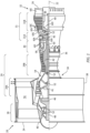
- FIG. 1 is a side cutaway illustration of the turbofan turbine engine 20.
- This turbine engine 20 extends along an axial centerline 22 between a forward, upstream airflow inlet 24 and an aft, downstream airflow exhaust 26.
- the turbine engine 20 includes a fan section 28, a compressor section 29, a combustor section 30, a turbine section 31 and an exhaust section 32 (partially shown in FIG. 1 ).
- the compressor section 29 includes a low pressure compressor (LPC) section 29A and a high pressure compressor (HPC) section 29B.
- the turbine section 31 includes a high pressure turbine (HPT) section 31A and a low pressure turbine (LPT) section 31B.
- the engine sections 28-31 are arranged sequentially along the axial centerline 22 within an engine housing 34.
- This engine housing 34 includes an inner case 36 (e.g., a core case) and an outer case 38 (e.g., a fan case).
- the inner case 36 may house one or more of the engine sections 29A-31B; e.g., an engine core.
- the outer case 38 may house at least the fan section 28.
- Each of the engine sections 28, 29A, 29B, 31A and 31B includes a respective rotor 40-44.
- Each of these rotors 40-44 includes a plurality of rotor blades arranged circumferentially around and connected to one or more respective rotor disks.
- the rotor blades may be formed integral with or mechanically fastened, welded, brazed, adhered and/or otherwise attached to the respective rotor disk(s).
- the fan rotor 40 is connected to a gear train 46, for example, through a fan shaft 48.
- the gear train 46 and the LPC rotor 41 are connected to and driven by the LPT rotor 44 through a low speed shaft 49.
- the HPC rotor 42 is connected to and driven by the HPT rotor 43 through a high speed shaft 50.
- the shafts 48-50 are rotatably supported by a plurality of bearings 52; e.g., rolling element and/or thrust bearings. Each of these bearings 52 is connected to the engine housing 34 by at least one stationary structure such as, for example, an annular support strut.
- bypass air During operation, air enters the turbine engine 20 through the airflow inlet 24. This air is directed through the fan section 28 and into a core flowpath 54 and a bypass flowpath 56.
- the core flowpath 54 extends sequentially through the engine sections 29A-32.
- the air within the core flowpath 54 may be referred to as "core air”.
- the bypass flowpath 56 extends through a bypass duct, which bypasses the engine core.
- the air within the bypass flowpath 56 may be referred to as "bypass air”.
- the core air is compressed by the LPC rotor 41 and the HPC rotor 42 and directed into a combustion chamber 58 of a combustor in the combustor section 30.
- Fuel is injected into the combustion chamber 58 and mixed with the compressed core air to provide a fuel-air mixture.
- This fuel air mixture is ignited and combustion products thereof flow through and sequentially cause the HPT rotor 43 and the LPT rotor 44 to rotate.
- the rotation of the HPT rotor 43 and the LPT rotor 44 respectively drive rotation of the HPC rotor 42 and the LPC rotor 41 and, thus, compression of the air received from a core airflow inlet.
- the rotation of the LPT rotor 44 also drives rotation of the fan rotor 40, which propels bypass air through and out of the bypass flowpath 56.
- the propulsion of the bypass air may account for a majority of thrust generated by the turbine engine 20, e.g., more than seventy-five percent (75%) of engine thrust.
- the turbine engine 20 of the present disclosure is not limited to the foregoing exemplary thrust ratio.
- the turbine engine 20 includes a plurality of fluid cooled components (e.g., 60A-H; generally referred to as "60") arranged within, for example, the combustor section 30, the turbine section 31 and/or the exhaust section 32.
- these fluid cooled components 60 include airfoils such as, but not limited to, a rotor blade airfoil (e.g., 60A, 60D) and a stator vane airfoil (e.g., 60B, 60C, 60H).
- fluid cooled components 60 include flowpath walls such as, but not limited to, a combustor wall (e.g., 60F), an exhaust duct wall (e.g., 60E), a shroud or other flowpath wall (e.g., 60G), a rotor blade platform and a stator vane platform.
- flowpath walls such as, but not limited to, a combustor wall (e.g., 60F), an exhaust duct wall (e.g., 60E), a shroud or other flowpath wall (e.g., 60G), a rotor blade platform and a stator vane platform.
- flowpath walls such as, but not limited to, a combustor wall (e.g., 60F), an exhaust duct wall (e.g., 60E), a shroud or other flowpath wall (e.g., 60G), a rotor blade platform and a stator vane platform.
- various other fluid cooled components may be included in the turbine engine 20,
- FIG. 2 illustrates a portion of one of the fluid cooled components 60 within the turbine engine 20.
- This fluid cooled component 60 has a component wall 62 (e.g., a sidewall or an endwall) configured with one or more cooling apertures 64.
- the component wall 62 has a thickness 66 that extends vertically (e.g., along a z-axis) between and to a first surface 68 and a second surface 70.
- the component first surface 68 may be configured as an interior and/or a cold side surface of the component wall 62.
- the component first surface 68 may at least partially form a peripheral boundary of a cooling fluid volume 72 (e.g., a cavity or a passage) along the component wall 62.
- the component first surface 68 may thereby be subject to relatively cool fluid (e.g., cooling air) supplied to the cooling fluid volume 72.
- This cooling fluid volume 72 may be an internal volume formed within the fluid cooled component 60 where, for example, the component is an airfoil. Alternatively, the cooling fluid volume 72 may be an external volume formed external to the fluid cooled component 60 where, for example, the component is a flowpath wall.
- the component second surface 70 may be configured as an exterior and/or a hot side surface of the component wall 62. The component second surface 70, for example, may at least partially form a peripheral boundary of a portion of, for example, the core flowpath 54 along the component wall 62. The component second surface 70 may thereby be subject to relative hot fluid (e.g., combustion products) flowing through the core flowpath 54 within, for example, one of the engine sections 30-32 of FIG. 1 .
- the component wall 62 of FIG. 3 includes a component substrate 74 and one or more external component coatings 76 and 78.
- the component substrate 74 at least partially or completely forms and carries the component first surface 68.
- the component substrate 74 has a thickness 80 that extends vertically (e.g., along the z-axis) between and to the component first surface 68 and a second surface 82 of the component substrate 74.
- This substrate second surface 82 may be configured as an exterior surface of the component substrate 74 prior to being (e.g., partially or completely) covered by the one or more component coatings 76 and 78.
- the substrate thickness 80 may be greater than one-half (1/2) of the wall thickness 66.
- the substrate thickness 80 for example, may be between two-third (2/3) and four-fifths (4/5) of the wall thickness 66.
- the component substrate 74 is constructed from substrate material 84.
- This substrate material 84 may be an electrically conductive material.
- the substrate material 84 may be or otherwise include metal.
- the metal include, but are not limited to, nickel (Ni), titanium (Ti), aluminum (Al), chromium (Cr), cobalt (Co), and alloys thereof.
- the metal for example, may be a nickel or cobalt based superalloy such as, but not limited to, PWA 1484 or PWA 1429.
- the inner coating 76 may be configured as a bond coating between the component substrate 74 and the outer coating 78.
- the inner coating 76 of FIG. 3 is bonded (e.g., directly) to the substrate second surface 82.
- the inner coating 76 at least partially or completely covers the substrate second surface 82 (e.g., along an x-y plane of FIG. 2 ).
- the inner coating 76 has a thickness 86 that extends vertically (e.g., along the z-axis) between and to component substrate 74 and the outer coating 78.
- This inner coating thickness 86 may be less than one-seventh (1/7) of the wall thickness 66.
- the inner coating thickness 86 for example, may be between one-eighth (1/8) and one-fortieth (1/40) of the wall thickness 66.
- the inner coating 76 is constructed from inner coating material 88.
- This inner coating material 88 may be an electrically conductive material.
- the inner coating material 88 may be or otherwise include metal. Examples of the metal include, but are not limited to, MCrAlY and MAlCrX, where "M” is nickel (Ni), cobalt (Co), iron (Fe) or any combination thereof, and where "Y” or “X” is hafnium (Hf), yttrium (Y), silicon (Si) or any combination thereof.
- the MCrAlY and MAlCrX may be further modified with strengthening elements such as, but not limited to, tantalum (Ta), rhenium (Re), tungsten (W), molybdenum (Mo) or any combination thereof.
- strengthening elements such as, but not limited to, tantalum (Ta), rhenium (Re), tungsten (W), molybdenum (Mo) or any combination thereof.
- An example of the MCrAlY is PWA 286.
- the inner coating 76 may be formed from a single layer of the inner coating material 88.
- the inner coating 76 may alternatively be formed from a plurality of layers of the inner coating material 88, where the inner coating material 88 within each of those inner coating layers may be the same as one another or different from one another.
- the outer coating 78 may be configured as a protective coating for the component substrate 74 and, more generally, the fluid cooled component 60.
- the outer coating 78 may be configured as a thermal barrier layer and/or an environmental layer.
- the outer coating 78 at least partially or completely forms and carries the component second surface 70.
- the outer coating 78 of FIG. 2 is bonded (e.g., directly) to a second (e.g., exterior) surface 90 of the inner coating 76.
- the outer coating 78 at least partially or completely covers the inner coating second surface 90 as well as the underlying substrate second surface 82 (e.g., along an x-y plane of FIG. 2 ).
- the outer coating 78 has a thickness 92 that extends vertically (e.g., along the z-axis) between and to the inner coating 76 and the component second surface 70.
- This outer coating thickness 92 may be less than one-half (1/2) of the wall thickness 66.
- the outer coating thickness 92 for example, may be between one-third (1/3) and one-eighth (1/8) of the wall thickness 66.
- the outer coating thickness 92 may be greater than the inner coating thickness 86.
- the outer coating 78 is constructed from outer coating material 94.
- This outer coating material 94 may be a non-electrically conductive material.
- the outer coating material 88 may be or otherwise include ceramic. Examples of the ceramic include, but are not limited to, yttria stabilized zirconia (YSZ) and gadolinium zirconate (GdZ).
- the outer coating material 94 of the present disclosure is not limited to non-electrically conductive materials. In other embodiments, for example, the outer coating material 94 may be an electrically conductive material; e.g., metal.
- the outer coating 78 may be formed from a single layer of the outer coating material 94.
- the outer coating 78 may alternatively be formed from a plurality of layers of the outer coating material 94, where the outer coating material 94 within each of those outer coating layers may be the same as one another or different from one another.
- the outer coating 78 may include a thin interior layer of the YSZ and a thicker exterior later of the GdZ.
- Each of the cooling apertures 64 extends along a respective longitudinal centerline 96 between and to an inlet 98 of the respective cooling aperture 64 and an outlet 100 of the respective cooling aperture 64.
- the cooling aperture inlet 98 of FIG. 3 is located in the component first surface 68.
- the cooling aperture inlet 98 thereby fluidly couples its respective cooling aperture 64 with the cooling fluid volume 72 along the component first surface 68.
- the cooling aperture outlet 100 of FIG. 3 is located in the component second surface 70.
- the cooling aperture outlet 100 thereby fluidly couples its respective cooling aperture 64 with the core flowpath 54 along the component second surface 70.
- Each of the cooling apertures 64 may include a meter section 102 and a diffuser section 104.
- the meter section 102 is disposed at (e.g., on, adjacent or proximate) the cooling aperture inlet 98.
- the meter section 102 is configured to meter (e.g., regulate) a flow of cooling fluid flowing from the cooling fluid volume 72, through the substrate material 84, to the diffuser section 104.
- the diffuser section 104 is disposed at the cooling aperture outlet 100.
- the diffuser section 104 is configured to diffuse the cooling fluid exhausted (e.g., directed out) from the cooling aperture outlet 100 into, for example, a film for cooling a downstream portion of the component second surface 70.
- the meter section 102 of FIG. 3 extends longitudinally along the longitudinal centerline 96 within (e.g., partially into) the component substrate 74. More particularly, the meter section 102 extends longitudinally along a meter segment 106 of the longitudinal centerline 96 (e.g., a centerline of the meter section 102) from the cooling aperture inlet 98 to an outlet 108 of the meter section 102.
- the meter section outlet 108 of FIG. 3 is disposed vertically within the component substrate 74 intermediately between the component first surface 68 and the substrate second surface 82. The meter section outlet 108 of FIG. 3 is thereby vertically recessed into the component substrate 74 by a vertical distance 110 (e.g., along the z-axis).
- the longitudinal centerline 96 and its (e.g., entire) meter segment 106 of FIG. 3 are angularly offset from the component first surface 68 by an included angle 112.
- This meter segment angle 112 may be an acute angle.
- the meter segment angle 112, for example, may be between ten degrees (10°) and eighty degrees (80°); e.g., between twenty degrees (20°) and thirty degrees (30°).
- the meter section 102 has a longitudinal length 114 measured along the meter segment 106 between the cooling aperture inlet 98 and the meter section outlet 108.
- the meter section 102 has a lateral width 116 (e.g., diameter) measured along a line perpendicular to the meter section 102 of the longitudinal centerline 96.
- the meter section lateral width 116 may be different (e.g., smaller or larger) than or equal to the meter section longitudinal length 114.
- the meter section 102 has a cross-sectional geometry when viewed, for example, in a plane perpendicular to its meter segment 106 (or the x-y plane). This meter section cross-sectional geometry may be uniform along the longitudinal length 114 of the meter section 102. Referring to FIG. 4 , the meter section cross-sectional geometry may be circular, oval, elliptical or otherwise annular in shape. The present disclosure, however, is not limited to such exemplary annular shapes.
- the diffuser section 104 of FIG. 3 extends longitudinally along the longitudinal centerline 96 out of the component substrate 74, through the inner coating 76 and the outer coating 78. More particularly, the diffuser section 104 of FIG. 3 extends longitudinally along a diffuser segment 118 of the longitudinal centerline 96 (e.g., a centerline of the diffuser section 104) from an inlet 120 of the diffuser section 104 (here, the same as the meter section outlet 108), through the materials 84, 88 and 94, to the cooling aperture outlet 100.
- the diffuser section inlet 120 of FIG. 3 is disposed vertically within the component substrate 74 intermediately between the component first surface 68 and the substrate second surface 82.
- the diffuser section inlet 120 of FIG. 3 is thereby vertically recessed into the component substrate 74 by the vertical distance 110 (e.g., along the z-axis).
- the longitudinal centerline 96 and its (e.g., entire) diffuser segment 118 of FIG. 3 are angularly offset from the component second surface 70 by an included angle 122.
- This diffuser segment angle 122 may be an acute angle.
- the diffuser segment angle 122 for example, may be between twenty degrees (20°) and eighty degrees (80°); e.g., between thirty-five degrees (35°) and fifty-five degrees (55°).
- the diffuser segment angle 122 of FIG. 3 is different (e.g., less) than the meter segment angle 112.
- the diffuser segment 118 may thereby be angularly offset from the meter segment 106.
- the diffuser section 104 has a longitudinal length 124 measured along the diffuser segment 118 between the diffuser section inlet 120 and the cooling aperture outlet 100. This diffuser section longitudinal length 124 may be equal to or different (e.g., less or greater) than the meter section longitudinal length 114.
- the diffuser section 104 has a lateral width 126, 128 (see FIG. 4 ) measured along a respective line perpendicular to the diffuser segment 118 of the longitudinal centerline 96.
- the diffuser section lateral width 126, 128 may be different (e.g., smaller or larger) than or equal to the diffuser section longitudinal length 124.
- the diffuser section lateral width 126, 128 of FIGS. 3 and 4 at other locations along the longitudinal centerline 96 may be greater than meter section lateral width 116. More particularly, the diffuser section 104 laterally diverges as the diffuser section 104 projects longitudinally away from the meter section 102 towards or to the cooling aperture outlet 100.
- the diffuser section 104 has a cross-sectional geometry when viewed, for example, in a plane perpendicular to its diffuser segment 118. This diffuser section cross-sectional geometry changes as the diffuser section 104 projects longitudinally away from the meter section 102, sequentially through the materials 84, 88 and 94 of FIG. 3 , to the cooling aperture outlet 100.
- the cooling aperture outlet 100 may have a complex cross-sectional geometry when viewed, for example, a plane parallel with the component second surface 70 (e.g., the x-y plane).
- This outlet cross-sectional geometry may include a (e.g., curved or straight) leading edge section 132, a (e.g., curved or straight) trailing edge section 134 and opposing (e.g., curved or straight) sidewall sections 136A and 136B (generally referred to as "136").
- Each of the sidewall sections 136 extends between and to respective ends of the leading and the trailing edge sections 132 and 134.
- a lateral width of the leading edge section 132 may be different (e.g., smaller) than a lateral width of the trailing edge section 134.
- the sidewall sections 136 may thereby generally laterally diverge away from one another as the sidewall sections 136 extend from the leading edge section 132 to the trailing edge section 134.
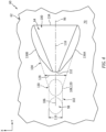
- the diffuser section 104 may be configured as a single lobe diffuser section. In other embodiments, referring to FIGS. 5 and 6 , the diffuser section 104 may be configured as a multi-lobe diffuser section.
- Various other single lobe and multi-lobe diffuser sections for cooling apertures 64 are known in the art, and the present disclosure is not limited to any particular ones thereof. Further details on various multi-lobe diffuser sections can be found in U.S. Patent No. 9,598,979 , which is assigned to the assignee of the present disclosure and hereby incorporated herein by reference in its entirety.
- the component wall 62 may also include at least one internal coating 138.
- This internal coating 138 may be configured as a protective coating (e.g., oxidation resistant coating) for at least some or all of the substrate material 84 forming the respective cooling aperture 64 within the substrate material 84.
- the internal coating 138 may line at least a portion or all of the meter section 102.
- the internal coating 138 of FIG. 7 forms a (e.g., tubular, cylindrical) surface 140, which surface 140 forms a peripheral side of the meter section 102.
- the internal coating 138 may also line a portion or all of the diffuser section 104 formed within the substrate material 84.
- the internal coating 138 of FIG. 7 for example, also forms a surface segment 142 (or segments) forming a side of the diffuser section 104 within the aperture material 84; e.g., an upstream side segment of the diffuser section 104.
- the internal coating 138 may also form another surface segment 144 (or segments) forming another side of the diffuser section 104 within the aperture material 84; e.g., a downstream side surface segment of the diffuser section 104.
- the internal coating 138 may also form on some or all of the first surface 68 and/or the second surface 70.
- the internal coating 138 is constructed from internal coating material 146.
- This internal coating material 146 may be an electrically conductive material.
- the internal coating material 146 may be or otherwise include metal.
- the internal coating 138 for example, may be an aluminide coating, a chromide coating, a platinum-aluminum (PtAl) coating or a nickel-cobalt-chromium-aluminum-yttrium (NiCoCrAlY) coating.
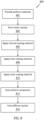
- FIG. 8 is a flow diagram of a method 800 for manufacturing a fluid cooled component.
- the method 800 is described below with reference to the fluid cooled component 60 described above.
- the method 800 of the present disclosure is not limited to manufacturing such an exemplary fluid cooled component.
- a preform substrate 74' is provided.
- the preform substrate 74' may generally have the configuration (e.g., shape, size, etc.) of the substrate for the fluid cooled component 60 to be formed (e.g., see FIGS. 3 and 7 ).
- the preform substrate 74' of FIG. 9 does not include any holes therein for forming the cooling apertures 64.
- the meter section 102 of a respective cooling aperture 64 is formed in the preform substrate 74'.
- a portion of the substrate material 84 is machined away (from the exterior of the preform substrate 74') to form, for example, a preform aperture 148.
- This preform aperture 148 of FIG. 10 extends along the meter segment 106 of the longitudinal centerline 96 (e.g., completely) through the substrate material 84 between and to the second surface 82 of the preform substrate 74' and the first surface 68 of the preform substrate 74'.
- a first portion 150 of the preform aperture 148 of FIG. 10 (e.g., partially or completely) forms the meter section 102.
- a second portion 152 of the preform aperture 148 of FIG. 10 forms a portion of the later-to-be-formed diffuser section 104.
- the preform aperture 148 and the meter section 102 may be formed in the (e.g., electrically conductive, metal) substrate material 84 using a preform aperture / meter section machining process.
- This preform aperture / meter section machining process may be selected to quickly, precisely and efficiently form the preform aperture 148 and the meter section 102 in the electrically conductive, metal substrate material 84.
- the preform aperture / meter section machining process for example, may be an electrical discharge machining (EDM) process.
- EDM electrical discharge machining
- the present disclosure is not limited to such an exemplary preform aperture / meter section machining process.
- the preform aperture 148 and the meter section 102 may also or alternatively be formed using one or more other machining processes such as, but not limited to, a laser machining (e.g., ablation) process, a water-jet guided laser (WJGL) machining process, an abrasive water jet (AWJ) machining process, an electron beam machining process, and a mechanical drilling process.
- a laser machining e.g., ablation
- WJGL water-jet guided laser
- AAWJ abrasive water jet
- a preform internal coating 138' is applied to the preform substrate 74'.
- the internal coating material 146 may be applied (e.g., deposited) onto a surface forming the preform aperture 148 thereby providing a lined preform aperture / a lined meter section.
- the internal coating material 146 may also be applied (e.g., deposited) onto at least a portion (or an entirety) of the second surface 82 of the preform substrate 74' and/or onto at least a portion (or an entirety) of the first surface 68 of the preform substrate 74'.
- the internal coating material 146 may be applied using various internal coating application techniques.
- the preform internal coating 138' of FIG. 11 may generally have the configuration of the internal coating 138 for the fluid cooled component to be formed (e.g., see FIG. 7 ).
- a preform inner coating 76' is applied over the preform substrate 74'.
- the inner coating material 88 may be applied (e.g., deposited) onto the second surface 82 of the preform substrate 74'.
- the inner coating material 88 may be applied using various inner coating application techniques. Examples of the inner coating application techniques include, but are not limited to, a physical vapor deposition (PVD) process, chemical vapor deposition (CVD) process, a plating process, and a thermal spray process (e.g., a plasma spray (PS) process, a high velocity oxygen fuel (HVOF) process, high velocity air fuel (HVAF) process, a wire spray process or a combustion spray process).
- PVD physical vapor deposition
- CVD chemical vapor deposition
- HVAF high velocity air fuel
- the inner coating application may be performed via a non-line-of-sight (NLOS) coating process or a direct-line-of-sight (DLOS) coating process.
- NLOS non-line-of-sight
- DLOS direct-line-of-sight
- the preform inner coating 76' of FIG. 12A may generally have the configuration of the inner coating 76 for the fluid cooled component 60 to be formed (e.g., see FIGS. 3 and 7 ).
- the inner coating material 88 may at least partially or completely cover or otherwise cap / plug an end 154 of the preform aperture 148.
- the inner coating material 88 may at least partially or completely cover or otherwise cap / plug an end 154 of the preform aperture 148.
- at least a portion or an entirety of the preform aperture end 154 may remain open (e.g., uncovered, unplugged) as shown, for example, in FIGS. 12B and 12C .
- a preform outer coating 78' is applied over the preform substrate 74' and the preform inner coating 76'.
- the outer coating material 94 may be applied (e.g., deposited) onto the second surface 90 of the preform inner coating 76'.
- the outer coating material 94 may be applied using various outer coating application techniques.
- Examples of the outer coating application techniques include, but are not limited to, a physical vapor deposition (PVD) process (e.g., an electron-beam PVD process), chemical vapor deposition (CVD) process, a thermal spray process (e.g., a plasma spray (PS) process, a high velocity oxygen fuel (HVOF) process, high velocity air fuel (HVAF) process, a wire spray process or a combustion spray process).
- PVD physical vapor deposition
- CVD chemical vapor deposition
- thermal spray process e.g., a plasma spray (PS) process, a high velocity oxygen fuel (HVOF) process, high velocity air fuel (HVAF) process, a wire spray process or a combustion spray process.
- the outer coating application may be performed via a non-line-of-sight (NLOS) coating process or a direct-line-of-sight (DLOS) coating process.
- NLOS non-line-of-sight
- DLOS direct-line-of-sight
- the outer coating material 94 may at least partially or completely (e.g., further) cover or otherwise cap / plug the preform aperture end 154 of the preform aperture 148.
- the preform aperture end 154 may remain open (e.g., uncovered, unplugged) as shown, for example, in FIGS. 13B and 13C .
- the combination of the preform substrate 74', the preform internal coating 138', the preform inner coating 76' and the preform outer coating 78' may provide a preform component 60'.
- This preform component 60' of FIG. 13 may generally have the configuration of the fluid cooled component 60 to be formed (e.g., see FIGS. 3 and 7 ).
- the preform component 60' of FIG. 13 does not include any holes for forming the diffuser sections 104.
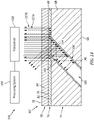
- step 812 at least a portion of the preform component 60' is scanned with a non-contact, non-destructive imaging system 156.
- this imaging system 156 may be configured as a microwave imaging system.
- the imaging system 156 of FIG. 14 may include a microwave transceiver 158 (or a transmitter and a receiver).
- This transceiver 158 (or the transmitter) is configured to direct (e.g., transmit) microwaves (e.g., 157A) into the preform component 60' from the exterior of the preform component 60'.
- microwaves include electromagnetic waves with a predetermined frequency (or frequency range) within a microwave frequency ban of three-hundred mega-Hertz (300MHz) and three-hundred giga-Hertz (300GHz).
- the specific frequency (or frequency range) may be selected / tuned based on the material composition of the preform component 60' and/or the specific geometric configuration of the preform aperture 148.
- the microwaves may be selected to travel through portions (certain component materials) of the preform component 60'. However, the microwaves may be selected to reflect against other portions (certain component materials and/or gas pockets formed by the preform aperture 148) of the preform component 60'. The microwaves may also or alternatively be selected to reflect against certain geometric features; e.g., surfaces, etc. At least some of the reflected microwaves (e.g., 157B) may travel back to and may be received by the transceiver 158 (or the receiver). The imaging system 156 may transmit information associated with the reflected microwaves as scan data - imaging system output data.
- the scan data may be indicative of an internal structure of the scanned portion of the preform component 60'.
- the scan data may be used to provide a feature map of the internal structure of the scanned portion of the preform component 60'.
- This feature map may include locations and/or dimensional information for the preform aperture 148.
- the feature map may also or alternatively include locations and/or dimensional information for one or more of the coatings and/or the preform substrate 74'.
- a processing system 159 e.g., a computer system
- the diffuser section 104 of the respective cooling aperture 64 is formed in the preform component 60' using the scan data as shown, for example, in FIG. 15 .
- the preform aperture 148 may be completely covered or otherwise obscured by one or more of the external coatings 76' and 78' (see FIG. 14 )
- the scan data and the preform aperture location and/or orientation information determined therefrom may be used to locate a position of where and/or an orientation of how the diffuser section 104 should be formed in the preform component 60'.
- the diffuser section 104 may then be formed at this location / orientation such that the diffuser section 104 substantially or completely aligns with the meter section 104 of the same respective cooling aperture 64.
- the diffuser segment 118 of the longitudinal centerline 96 may be coincident with the meter segment 106 of the longitudinal centerline 96 at the interface 130.
- the orifices 108 and 120 may thereby be (e.g., completely) aligned (e.g., in the x-y plane).
- there may be acceptable alignment between the diffuser section 104 and the meter section 102 where, for example, a lateral misalignment 160 between the longitudinal centerline segments 106 and 118 at the interface 130 is less than a (e.g., predetermined) threshold.
- the orifices 108 and 120 may thereby be slightly misaligned, but still within design specifications for example.
- a portion of the outer coating material 94, a portion of the inner coating material 88 and a portion of the underlying substrate material 84 is machined away (from the exterior of the preform component 60') to provide the respective diffuser section 104.
- the diffuser section 104 may be formed in the various materials of the preform component 60' using a diffuser section machining process. This diffuser section machining process is selected to form the diffuser section 104 in the various different electrically conductive and non-electrically conductive materials in the preform component 60'. The diffuser section machining process is also selected to provide the diffuser section 104 with a precise finish geometry.
- the diffuser section machining process examples include, but are not limited to, a laser machining (e.g., ablation) process, a water-jet guided laser (WJGL) machining process, an abrasive water jet (AWJ) machining process, an electron beam machining process, and a mechanical drilling process.
- a laser machining e.g., ablation
- WJGL water-jet guided laser
- AAWJ abrasive water jet
- electron beam machining process examples include, but are not limited to, a mechanical drilling process.
- the method 800 is described above as partially forming a portion of the diffuser section 104 by forming the preform aperture 148 (see FIG. 10 ) in the step 804.
- a respective portion of the diffuser section 104 may be completely formed within the preform substrate 74' such that the downstream side surface segment 144 of the diffuser section 104 (see FIG. 7 ) is also coated with the internal coating material 146 during the coating step 806.
- the scanning step 812 may be replaced by (or performed in conjunction with) a modeling step.
- a processing system e.g., the system 159 may computationally model one or more of the external preform coatings 76', 78' over the preform substrate 74' (prior to or following application of those coatings 76', 78') to predict a geometry of the preform component 60'. More particularly, the processing system may model predicted changes in the external preform coatings 76', 78' over the preform substrate 74' due to, for example, manufacturing tolerances.
- the processing system may more accurately locate the position and/or the orientation of the preform aperture 148 and its meter section 102 within the preform component 60', even where apertures 148, 102 are covered or otherwise visually obscured by the external preform coatings 76', 78'.
- Model data associated with the modeling may thereby be used to form a respective diffuser section 104 in the preform component 60' aligned with the meter section 102.
- the modeling may be performed using artificial intelligence (AI).
- AI artificial intelligence
- the modeling may also or alternatively be performed using machine learning where, for example, information learned from manufacturing one or more previous fluid cooled components 60 may be applied to manufacturing of the present fluid cooled component 60.
- the method 800 is described above with respect to formation of a single cooling aperture 64 of the fluid cooled component 60.
- the fluid cooled component 60 may be formed with multiple of the cooling apertures 64, for example, by repeating the steps 804 and 814.
- the step 804 may be repeated multiple times before the coating steps 806, 808 and 810.
- the step 814 may then be repeated multiple times following the scanning step 812.
- FIG. 17 is a flow diagram 1700 of a method for inspecting a fluid cooled component.
- the method 1700 is described below with reference to the fluid cooled component 60 described above.
- the method 1700 of the present disclosure is not limited to inspecting such an exemplary fluid cooled component.
- step 1702 the fluid cooled component 60 is provided.
- step 1704 at least a portion of the fluid cooled component 60 is scanned using the imaging system 156.
- This scanning step 1704 may be performed in a similar manner as described above with respect to the scanning step 812 to provide scan data.
- This scan data may be indicative of alignment between the diffuser section 104 and the meter section 102 of a respective one (or more) of the cooling apertures 64.
- the scan data is processed to evaluate the alignment between the diffuser section 104 and the meter section 102 of a respective one (or more) of the cooling apertures 64.
- the processing system 159 may determine the diffuser section 104 and the meter section 102 are properly aligned when the longitudinal centerline segments 106 and 118 are coincident at the interface 130 (e.g., see FIG. 15 ).
- the processing system 159 may determine the diffuser section 104 and the meter section 102 satisfying a design specification when, for example, the lateral misalignment 160 of FIG. 16 between the longitudinal centerline segments 106 and 118 at the interface 130 is less than a (e.g., predetermined) threshold.
- the processing system 159 may determine the diffuser section 104 and the meter section 102 are misaligned and out of (e.g., does not satisfy) the design specification when, for example, the lateral misalignment 160 of FIG. 16 between the longitudinal centerline segments 106 and 118 at the interface 130 is equal to or greater than the threshold.
- this threshold may have different values at different locations circumferentially about the interface (e.g., in the x-y plane).
- the processing system 159 may subsequently provide an indication of alignment.
- the fluid cooled component 60 may be identified for further downstream processing and/or service; e.g., installation within the turbine engine 20.
- the alignment between the sections 102 and 104 is not acceptable (e.g., for a single cooling aperture 64, or for a certain number of cooling apertures 64 of a respective component 60)
- the fluid cooled component 60 may be returned for further processing and/or scrapped.
- the method 800 and the method 1700 are described above with reference to a microwave imaging system for locating a hole beneath coating(s) 76, 78 and/or locating a true center of a hole partially obscured by the coating(s) 76, 78.
- the present disclosure is not limited to such an exemplary imaging system.
- the scanning may also or alternatively be performed by other non-contact, non-destructive imaging systems such as, but not limited to, a micro computed tomography (micro-CT) imaging system, a terahertz imaging system, a flash thermography system, etc.
- micro-CT micro computed tomography
Landscapes
- Engineering & Computer Science (AREA)
- Chemical & Material Sciences (AREA)
- Mechanical Engineering (AREA)
- General Engineering & Computer Science (AREA)
- Materials Engineering (AREA)
- Chemical Kinetics & Catalysis (AREA)
- Metallurgy (AREA)
- Organic Chemistry (AREA)
- Physics & Mathematics (AREA)
- Optics & Photonics (AREA)
- Combustion & Propulsion (AREA)
- General Chemical & Material Sciences (AREA)
- Plasma & Fusion (AREA)
- Toxicology (AREA)
- Health & Medical Sciences (AREA)
- Fluid Mechanics (AREA)
- Turbine Rotor Nozzle Sealing (AREA)
Abstract
Description
- This disclosure (invention) relates generally to a turbine engine and, more particularly, to cooling apertures and formation thereof in a component of the turbine engine.
- A gas turbine engine includes various fluid cooled components such as turbine blades and turbine vanes. Such fluid cooled components may include one or more cooling apertures extending through a sidewall of the respective component. Various methods are known in the art for forming cooling apertures. While these known cooling aperture formation methods have various benefits, there is still room in the art form improvement.
- According to an aspect of the present invention, a manufacturing method is provided. During this method, a preform component is provided for a turbine engine. The preform component includes a substrate. A meter section of a cooling aperture is formed in the substrate. An internal coating is applied onto a surface of the meter section. An external coating is applied over the substrate. A diffuser section of the cooling aperture is formed in the external coating and the substrate to provide the cooling aperture.
- According to another aspect of the present invention, another manufacturing method is provided. During this method, a preform component is provided for a turbine engine. The preform component includes a substrate. A meter section is machined into the substrate. At least a portion of the meter section is lined with an internal coating to provide a lined meter section of a cooling aperture. An external coating is formed over the substrate with the lined meter section. At least a portion of a diffuser section of the cooling aperture is machined into the external coating.
- According to still another aspect of the present invention, a component is provided for a turbine engine. This component includes a substrate, an external coating, a plurality of cooling apertures and an internal coating. The substrate is configured from or otherwise includes metal. The external coating is over the metal substrate. The external coating is configured from or otherwise includes ceramic. A first of the cooling apertures includes a meter section and a diffuser section. The meter section is formed in the substrate. The diffuser section is formed in the substrate and the external coating. The internal coating at least partially lines the first of the cooling apertures within the substrate. The component is configured as an airfoil or a flowpath wall for the turbine engine.
- The following optional features may be applied to any of the above aspects.
- The substrate may be configured from or otherwise include metal. The internal coating may be configured as or otherwise include an aluminide coating. The external coating may be configured as or otherwise include ceramic.
- The internal coating may be configured as or otherwise include an aluminide coating.
- The diffuser section may be configured as or otherwise include a multi-lobed diffuser section.
- The substrate may be configured from or otherwise include metal. The external coating may be configured from or otherwise include ceramic.
- The method may also include applying a bond coating onto the substrate. The external coating may be applied onto the bond coating. The diffuser section may also be formed through the bond coating.
- The bond coating may be configured as or otherwise include MCrAlY or MAlCrX. The M may comprise at least one of nickel (Ni), cobalt (Co) or iron (Fe). The Y or the X may comprise at least one of hafnium (Hf), yttrium (Y) or silicon (Si).
- The method may also include applying a bond coating onto at least a portion of the internal coating. The external coating may be applied onto the bond coating. The diffuser section may also be formed through the bond coating.
- The meter section may be formed using an electrical discharge machining process.
- The diffuser section may be formed using a laser machining process.
- The preform component may be configured as or otherwise include a preform of an airfoil for the turbine engine.
- The preform component may be configured as or otherwise include a preform of a flowpath wall for the turbine engine.
- The method may also include modeling the external coating to predict a geometry of the preform component following the application of the external coating. The diffuser section may be formed in the external coating and the substrate based on the predicted geometry.
- The modeling may be performed using artificial intelligence.
- The modeling may be performed using machine learning.
- The method may also include scanning at least a portion of the substrate, the internal coating and the external coating with an imaging system to provide scan data indicative of an internal structure of the portion of the substrate, the internal coating and the external coating. The diffuser section may be formed in the external coating and the substrate based on the scan data.
- The imaging system may be configured as or otherwise include a microwave imaging system.
- The present disclosure may include any one or more of the individual features disclosed above and/or below alone or in any combination thereof.
- The foregoing features and the operation of the invention will become more apparent in light of the following description and the accompanying drawings.
-
-
FIG. 1 is a side cutaway illustration of a geared turbofan turbine engine. -
FIG. 2 is a perspective illustration of a portion of a fluid cooled component. -
FIG. 3 is a sectional illustration of a portion of the fluid cooled component taken along a centerline of a cooling aperture. -
FIG. 4 is a side illustration of a portion of the fluid cooled component and the cooling aperture. -
FIGS. 5 and 6 are side illustrations of portions of the fluid cooled component configured with various multi-lobed cooling apertures. -
FIG. 7 is a sectional illustration of a portion of the fluid cooled component taken along the centerline of the cooling aperture, where the fluid cooling component is further configured with an internal coating. -
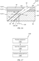
FIG. 8 is a flow diagram of a method for manufacturing a fluid cooled component. -
FIG. 9 is a sectional illustration of a portion of a preform substrate. -
FIG. 10 is a sectional illustration of a portion of the preform substrate configured with a preform aperture. -
FIG. 11 is sectional illustration of a portion of the preform substrate configured with a preform internal coating lining the preform aperture. -
FIG. 12A-C are sectional illustrations of a portion of the preform substrate configured with various first external coatings. -
FIGS. 13A-C are sectional illustrations of a portion of the preform substrate configured with various second external coatings. -
FIG. 14 is a sectional illustration of a portion of the preform substrate located proximate an imaging system. -
FIG. 15 is a sectional illustration of a portion of the preform substrate configured with a diffuser section. -
FIG. 16 is a sectional illustration of a portion of the preform substrate configured with a cooling aperture having a slight misalignment between its meter section and its diffuser section. -
FIG. 17 is a flow diagram of a method for inspecting a fluid cooled component. - The present disclosure includes methods for manufacturing fluid cooled components of a gas turbine engine. For ease of description, the turbine engine may be described below as a turbofan turbine engine. The present disclosure, however, is not limited to such an exemplary gas turbine engine. The turbine engine, for example, may alternatively be configured as a turbojet turbine engine, a turboprop turbine engine, a turboshaft turbine engine, a propfan turbine engine, a pusher fan turbine engine or an auxiliary power unit (APU) turbine engine. The turbine engine may be configured as a geared turbine engine or a direct drive turbine engine. The present disclosure is also not limited to aircraft applications. The turbine engine, for example, may alternatively be configured as a ground-based industrial turbine engine for power generation, or any other type of turbine engine which utilizes fluid cooled components.
-
FIG. 1 is a side cutaway illustration of theturbofan turbine engine 20. Thisturbine engine 20 extends along anaxial centerline 22 between a forward,upstream airflow inlet 24 and an aft,downstream airflow exhaust 26. Theturbine engine 20 includes afan section 28, acompressor section 29, acombustor section 30, aturbine section 31 and an exhaust section 32 (partially shown inFIG. 1 ). Thecompressor section 29 includes a low pressure compressor (LPC)section 29A and a high pressure compressor (HPC)section 29B. Theturbine section 31 includes a high pressure turbine (HPT)section 31A and a low pressure turbine (LPT)section 31B. - The engine sections 28-31 are arranged sequentially along the
axial centerline 22 within anengine housing 34. Thisengine housing 34 includes an inner case 36 (e.g., a core case) and an outer case 38 (e.g., a fan case). Theinner case 36 may house one or more of theengine sections 29A-31B; e.g., an engine core. Theouter case 38 may house at least thefan section 28. - Each of the
engine sections - The
fan rotor 40 is connected to agear train 46, for example, through afan shaft 48. Thegear train 46 and theLPC rotor 41 are connected to and driven by theLPT rotor 44 through alow speed shaft 49. TheHPC rotor 42 is connected to and driven by theHPT rotor 43 through ahigh speed shaft 50. The shafts 48-50 are rotatably supported by a plurality ofbearings 52; e.g., rolling element and/or thrust bearings. Each of thesebearings 52 is connected to theengine housing 34 by at least one stationary structure such as, for example, an annular support strut. - During operation, air enters the
turbine engine 20 through theairflow inlet 24. This air is directed through thefan section 28 and into acore flowpath 54 and abypass flowpath 56. Thecore flowpath 54 extends sequentially through theengine sections 29A-32. The air within thecore flowpath 54 may be referred to as "core air". Thebypass flowpath 56 extends through a bypass duct, which bypasses the engine core. The air within thebypass flowpath 56 may be referred to as "bypass air". - The core air is compressed by the
LPC rotor 41 and theHPC rotor 42 and directed into acombustion chamber 58 of a combustor in thecombustor section 30. Fuel is injected into thecombustion chamber 58 and mixed with the compressed core air to provide a fuel-air mixture. This fuel air mixture is ignited and combustion products thereof flow through and sequentially cause theHPT rotor 43 and theLPT rotor 44 to rotate. The rotation of theHPT rotor 43 and theLPT rotor 44 respectively drive rotation of theHPC rotor 42 and theLPC rotor 41 and, thus, compression of the air received from a core airflow inlet. The rotation of theLPT rotor 44 also drives rotation of thefan rotor 40, which propels bypass air through and out of thebypass flowpath 56. The propulsion of the bypass air may account for a majority of thrust generated by theturbine engine 20, e.g., more than seventy-five percent (75%) of engine thrust. Theturbine engine 20 of the present disclosure, however, is not limited to the foregoing exemplary thrust ratio. - The
turbine engine 20 includes a plurality of fluid cooled components (e.g., 60A-H; generally referred to as "60") arranged within, for example, thecombustor section 30, theturbine section 31 and/or theexhaust section 32. Examples of these fluid cooledcomponents 60 include airfoils such as, but not limited to, a rotor blade airfoil (e.g., 60A, 60D) and a stator vane airfoil (e.g., 60B, 60C, 60H). Other examples of the fluid cooledcomponents 60 include flowpath walls such as, but not limited to, a combustor wall (e.g., 60F), an exhaust duct wall (e.g., 60E), a shroud or other flowpath wall (e.g., 60G), a rotor blade platform and a stator vane platform. Of course, various other fluid cooled components may be included in theturbine engine 20, and the present disclosure is not limited to any particular types or configurations thereof. -
FIG. 2 illustrates a portion of one of the fluid cooledcomponents 60 within theturbine engine 20. This fluid cooledcomponent 60 has a component wall 62 (e.g., a sidewall or an endwall) configured with one ormore cooling apertures 64. - Referring to
FIG. 3 , thecomponent wall 62 has athickness 66 that extends vertically (e.g., along a z-axis) between and to afirst surface 68 and asecond surface 70. The componentfirst surface 68 may be configured as an interior and/or a cold side surface of thecomponent wall 62. The componentfirst surface 68, for example, may at least partially form a peripheral boundary of a cooling fluid volume 72 (e.g., a cavity or a passage) along thecomponent wall 62. The componentfirst surface 68 may thereby be subject to relatively cool fluid (e.g., cooling air) supplied to the coolingfluid volume 72. This coolingfluid volume 72 may be an internal volume formed within the fluid cooledcomponent 60 where, for example, the component is an airfoil. Alternatively, the coolingfluid volume 72 may be an external volume formed external to the fluid cooledcomponent 60 where, for example, the component is a flowpath wall. The componentsecond surface 70 may be configured as an exterior and/or a hot side surface of thecomponent wall 62. The componentsecond surface 70, for example, may at least partially form a peripheral boundary of a portion of, for example, thecore flowpath 54 along thecomponent wall 62. The componentsecond surface 70 may thereby be subject to relative hot fluid (e.g., combustion products) flowing through thecore flowpath 54 within, for example, one of the engine sections 30-32 ofFIG. 1 . - The
component wall 62 ofFIG. 3 includes acomponent substrate 74 and one or moreexternal component coatings component substrate 74 at least partially or completely forms and carries the componentfirst surface 68. Thecomponent substrate 74 has athickness 80 that extends vertically (e.g., along the z-axis) between and to the componentfirst surface 68 and asecond surface 82 of thecomponent substrate 74. This substratesecond surface 82 may be configured as an exterior surface of thecomponent substrate 74 prior to being (e.g., partially or completely) covered by the one ormore component coatings substrate thickness 80 may be greater than one-half (1/2) of thewall thickness 66. Thesubstrate thickness 80, for example, may be between two-third (2/3) and four-fifths (4/5) of thewall thickness 66. - The
component substrate 74 is constructed fromsubstrate material 84. Thissubstrate material 84 may be an electrically conductive material. Thesubstrate material 84, for example, may be or otherwise include metal. Examples of the metal include, but are not limited to, nickel (Ni), titanium (Ti), aluminum (Al), chromium (Cr), cobalt (Co), and alloys thereof. The metal, for example, may be a nickel or cobalt based superalloy such as, but not limited to, PWA 1484 or PWA 1429. - The
inner coating 76 may be configured as a bond coating between thecomponent substrate 74 and theouter coating 78. Theinner coating 76 ofFIG. 3 is bonded (e.g., directly) to the substratesecond surface 82. Theinner coating 76 at least partially or completely covers the substrate second surface 82 (e.g., along an x-y plane ofFIG. 2 ). Theinner coating 76 has athickness 86 that extends vertically (e.g., along the z-axis) between and tocomponent substrate 74 and theouter coating 78. Thisinner coating thickness 86 may be less than one-seventh (1/7) of thewall thickness 66. Theinner coating thickness 86, for example, may be between one-eighth (1/8) and one-fortieth (1/40) of thewall thickness 66. - The
inner coating 76 is constructed frominner coating material 88. Thisinner coating material 88 may be an electrically conductive material. Theinner coating material 88, for example, may be or otherwise include metal. Examples of the metal include, but are not limited to, MCrAlY and MAlCrX, where "M" is nickel (Ni), cobalt (Co), iron (Fe) or any combination thereof, and where "Y" or "X" is hafnium (Hf), yttrium (Y), silicon (Si) or any combination thereof. The MCrAlY and MAlCrX may be further modified with strengthening elements such as, but not limited to, tantalum (Ta), rhenium (Re), tungsten (W), molybdenum (Mo) or any combination thereof. An example of the MCrAlY is PWA 286. - The
inner coating 76 may be formed from a single layer of theinner coating material 88. Theinner coating 76 may alternatively be formed from a plurality of layers of theinner coating material 88, where theinner coating material 88 within each of those inner coating layers may be the same as one another or different from one another. - The
outer coating 78 may be configured as a protective coating for thecomponent substrate 74 and, more generally, the fluid cooledcomponent 60. Theouter coating 78, for example, may be configured as a thermal barrier layer and/or an environmental layer. Theouter coating 78 at least partially or completely forms and carries the componentsecond surface 70. Theouter coating 78 ofFIG. 2 is bonded (e.g., directly) to a second (e.g., exterior) surface 90 of theinner coating 76. Theouter coating 78 at least partially or completely covers the inner coatingsecond surface 90 as well as the underlying substrate second surface 82 (e.g., along an x-y plane ofFIG. 2 ). Theouter coating 78 has athickness 92 that extends vertically (e.g., along the z-axis) between and to theinner coating 76 and the componentsecond surface 70. Thisouter coating thickness 92 may be less than one-half (1/2) of thewall thickness 66. Theouter coating thickness 92, for example, may be between one-third (1/3) and one-eighth (1/8) of thewall thickness 66. Theouter coating thickness 92, however, may be greater than theinner coating thickness 86. - The
outer coating 78 is constructed fromouter coating material 94. Thisouter coating material 94 may be a non-electrically conductive material. Theouter coating material 88, for example, may be or otherwise include ceramic. Examples of the ceramic include, but are not limited to, yttria stabilized zirconia (YSZ) and gadolinium zirconate (GdZ). Theouter coating material 94 of the present disclosure is not limited to non-electrically conductive materials. In other embodiments, for example, theouter coating material 94 may be an electrically conductive material; e.g., metal. - The
outer coating 78 may be formed from a single layer of theouter coating material 94. Theouter coating 78 may alternatively be formed from a plurality of layers of theouter coating material 94, where theouter coating material 94 within each of those outer coating layers may be the same as one another or different from one another. For example, theouter coating 78 may include a thin interior layer of the YSZ and a thicker exterior later of the GdZ. - Each of the cooling
apertures 64 extends along a respectivelongitudinal centerline 96 between and to aninlet 98 of therespective cooling aperture 64 and anoutlet 100 of therespective cooling aperture 64. The coolingaperture inlet 98 ofFIG. 3 is located in the componentfirst surface 68. The coolingaperture inlet 98 thereby fluidly couples itsrespective cooling aperture 64 with the coolingfluid volume 72 along the componentfirst surface 68. The coolingaperture outlet 100 ofFIG. 3 is located in the componentsecond surface 70. The coolingaperture outlet 100 thereby fluidly couples itsrespective cooling aperture 64 with thecore flowpath 54 along the componentsecond surface 70. - Each of the
cooling apertures 64 may include ameter section 102 and adiffuser section 104. Themeter section 102 is disposed at (e.g., on, adjacent or proximate) the coolingaperture inlet 98. Themeter section 102 is configured to meter (e.g., regulate) a flow of cooling fluid flowing from the coolingfluid volume 72, through thesubstrate material 84, to thediffuser section 104. Thediffuser section 104 is disposed at the coolingaperture outlet 100. Thediffuser section 104 is configured to diffuse the cooling fluid exhausted (e.g., directed out) from the coolingaperture outlet 100 into, for example, a film for cooling a downstream portion of the componentsecond surface 70. - The
meter section 102 ofFIG. 3 extends longitudinally along thelongitudinal centerline 96 within (e.g., partially into) thecomponent substrate 74. More particularly, themeter section 102 extends longitudinally along ameter segment 106 of the longitudinal centerline 96 (e.g., a centerline of the meter section 102) from the coolingaperture inlet 98 to anoutlet 108 of themeter section 102. Themeter section outlet 108 ofFIG. 3 is disposed vertically within thecomponent substrate 74 intermediately between the componentfirst surface 68 and the substratesecond surface 82. Themeter section outlet 108 ofFIG. 3 is thereby vertically recessed into thecomponent substrate 74 by a vertical distance 110 (e.g., along the z-axis). - The
longitudinal centerline 96 and its (e.g., entire)meter segment 106 ofFIG. 3 are angularly offset from the componentfirst surface 68 by an includedangle 112. Thismeter segment angle 112 may be an acute angle. Themeter segment angle 112, for example, may be between ten degrees (10°) and eighty degrees (80°); e.g., between twenty degrees (20°) and thirty degrees (30°). - The
meter section 102 has alongitudinal length 114 measured along themeter segment 106 between the coolingaperture inlet 98 and themeter section outlet 108. Themeter section 102 has a lateral width 116 (e.g., diameter) measured along a line perpendicular to themeter section 102 of thelongitudinal centerline 96. The metersection lateral width 116 may be different (e.g., smaller or larger) than or equal to the meter sectionlongitudinal length 114. - The
meter section 102 has a cross-sectional geometry when viewed, for example, in a plane perpendicular to its meter segment 106 (or the x-y plane). This meter section cross-sectional geometry may be uniform along thelongitudinal length 114 of themeter section 102. Referring toFIG. 4 , the meter section cross-sectional geometry may be circular, oval, elliptical or otherwise annular in shape. The present disclosure, however, is not limited to such exemplary annular shapes. - The
diffuser section 104 ofFIG. 3 extends longitudinally along thelongitudinal centerline 96 out of thecomponent substrate 74, through theinner coating 76 and theouter coating 78. More particularly, thediffuser section 104 ofFIG. 3 extends longitudinally along adiffuser segment 118 of the longitudinal centerline 96 (e.g., a centerline of the diffuser section 104) from aninlet 120 of the diffuser section 104 (here, the same as the meter section outlet 108), through thematerials aperture outlet 100. Thediffuser section inlet 120 ofFIG. 3 is disposed vertically within thecomponent substrate 74 intermediately between the componentfirst surface 68 and the substratesecond surface 82. Thediffuser section inlet 120 ofFIG. 3 is thereby vertically recessed into thecomponent substrate 74 by the vertical distance 110 (e.g., along the z-axis). - The
longitudinal centerline 96 and its (e.g., entire)diffuser segment 118 ofFIG. 3 are angularly offset from the componentsecond surface 70 by an includedangle 122. Thisdiffuser segment angle 122 may be an acute angle. Thediffuser segment angle 122, for example, may be between twenty degrees (20°) and eighty degrees (80°); e.g., between thirty-five degrees (35°) and fifty-five degrees (55°). Thediffuser segment angle 122 ofFIG. 3 is different (e.g., less) than themeter segment angle 112. Thediffuser segment 118 may thereby be angularly offset from themeter segment 106. - The
diffuser section 104 has alongitudinal length 124 measured along thediffuser segment 118 between thediffuser section inlet 120 and the coolingaperture outlet 100. This diffuser sectionlongitudinal length 124 may be equal to or different (e.g., less or greater) than the meter sectionlongitudinal length 114. Thediffuser section 104 has alateral width 126, 128 (seeFIG. 4 ) measured along a respective line perpendicular to thediffuser segment 118 of thelongitudinal centerline 96. The diffusersection lateral width longitudinal length 124. The diffusersection lateral width FIGS. 3 and4 at theinterface 130 between thediffuser section 104 and themeter section 102 is equal to the metersection lateral width 116. However, the diffusersection lateral width FIGS. 3 and4 at other locations along thelongitudinal centerline 96 may be greater than metersection lateral width 116. More particularly, thediffuser section 104 laterally diverges as thediffuser section 104 projects longitudinally away from themeter section 102 towards or to the coolingaperture outlet 100. - The
diffuser section 104 has a cross-sectional geometry when viewed, for example, in a plane perpendicular to itsdiffuser segment 118. This diffuser section cross-sectional geometry changes as thediffuser section 104 projects longitudinally away from themeter section 102, sequentially through thematerials FIG. 3 , to the coolingaperture outlet 100. - Referring to
FIG. 4 , the coolingaperture outlet 100 may have a complex cross-sectional geometry when viewed, for example, a plane parallel with the component second surface 70 (e.g., the x-y plane). This outlet cross-sectional geometry may include a (e.g., curved or straight) leadingedge section 132, a (e.g., curved or straight) trailingedge section 134 and opposing (e.g., curved or straight)sidewall sections edge sections leading edge section 132 may be different (e.g., smaller) than a lateral width of the trailingedge section 134. The sidewall sections 136 may thereby generally laterally diverge away from one another as the sidewall sections 136 extend from theleading edge section 132 to the trailingedge section 134. - In some embodiments, referring to
FIG. 4 , thediffuser section 104 may be configured as a single lobe diffuser section. In other embodiments, referring toFIGS. 5 and 6 , thediffuser section 104 may be configured as a multi-lobe diffuser section. Various other single lobe and multi-lobe diffuser sections for coolingapertures 64 are known in the art, and the present disclosure is not limited to any particular ones thereof. Further details on various multi-lobe diffuser sections can be found inU.S. Patent No. 9,598,979 - In some embodiments, referring to
FIG. 7 , thecomponent wall 62 may also include at least oneinternal coating 138. Thisinternal coating 138 may be configured as a protective coating (e.g., oxidation resistant coating) for at least some or all of thesubstrate material 84 forming therespective cooling aperture 64 within thesubstrate material 84. - The
internal coating 138 may line at least a portion or all of themeter section 102. Theinternal coating 138 ofFIG. 7 , for example, forms a (e.g., tubular, cylindrical)surface 140, which surface 140 forms a peripheral side of themeter section 102. Theinternal coating 138 may also line a portion or all of thediffuser section 104 formed within thesubstrate material 84. Theinternal coating 138 ofFIG. 7 , for example, also forms a surface segment 142 (or segments) forming a side of thediffuser section 104 within theaperture material 84; e.g., an upstream side segment of thediffuser section 104. Depending on specific cooling aperture formation techniques (discussed below in further detail), theinternal coating 138 may also form another surface segment 144 (or segments) forming another side of thediffuser section 104 within theaperture material 84; e.g., a downstream side surface segment of thediffuser section 104. Theinternal coating 138 may also form on some or all of thefirst surface 68 and/or thesecond surface 70. - The
internal coating 138 is constructed frominternal coating material 146. Thisinternal coating material 146 may be an electrically conductive material. Theinternal coating material 146, for example, may be or otherwise include metal. Theinternal coating 138, for example, may be an aluminide coating, a chromide coating, a platinum-aluminum (PtAl) coating or a nickel-cobalt-chromium-aluminum-yttrium (NiCoCrAlY) coating. -
FIG. 8 is a flow diagram of amethod 800 for manufacturing a fluid cooled component. For ease of description, themethod 800 is described below with reference to the fluid cooledcomponent 60 described above. Themethod 800 of the present disclosure, however, is not limited to manufacturing such an exemplary fluid cooled component. - In
step 802, apreform substrate 74' is provided. Referring toFIG. 9 , thepreform substrate 74' may generally have the configuration (e.g., shape, size, etc.) of the substrate for the fluid cooledcomponent 60 to be formed (e.g., seeFIGS. 3 and7 ). Thepreform substrate 74' ofFIG. 9 , however, does not include any holes therein for forming the coolingapertures 64. - In
step 804, themeter section 102 of arespective cooling aperture 64 is formed in thepreform substrate 74'. For example, referring toFIG. 10 , a portion of thesubstrate material 84 is machined away (from the exterior of thepreform substrate 74') to form, for example, apreform aperture 148. Thispreform aperture 148 ofFIG. 10 extends along themeter segment 106 of the longitudinal centerline 96 (e.g., completely) through thesubstrate material 84 between and to thesecond surface 82 of thepreform substrate 74' and thefirst surface 68 of thepreform substrate 74'. A first portion 150 of thepreform aperture 148 ofFIG. 10 (e.g., partially or completely) forms themeter section 102. Asecond portion 152 of thepreform aperture 148 ofFIG. 10 forms a portion of the later-to-be-formed diffuser section 104. - The
preform aperture 148 and themeter section 102 may be formed in the (e.g., electrically conductive, metal)substrate material 84 using a preform aperture / meter section machining process. This preform aperture / meter section machining process may be selected to quickly, precisely and efficiently form thepreform aperture 148 and themeter section 102 in the electrically conductive,metal substrate material 84. The preform aperture / meter section machining process, for example, may be an electrical discharge machining (EDM) process. The present disclosure, however, is not limited to such an exemplary preform aperture / meter section machining process. Thepreform aperture 148 and themeter section 102, for example, may also or alternatively be formed using one or more other machining processes such as, but not limited to, a laser machining (e.g., ablation) process, a water-jet guided laser (WJGL) machining process, an abrasive water jet (AWJ) machining process, an electron beam machining process, and a mechanical drilling process. - In
step 806, a preform internal coating 138' is applied to thepreform substrate 74'. For example, referring toFIG. 11 , theinternal coating material 146 may be applied (e.g., deposited) onto a surface forming thepreform aperture 148 thereby providing a lined preform aperture / a lined meter section. Theinternal coating material 146 may also be applied (e.g., deposited) onto at least a portion (or an entirety) of thesecond surface 82 of thepreform substrate 74' and/or onto at least a portion (or an entirety) of thefirst surface 68 of thepreform substrate 74'. Theinternal coating material 146 may be applied using various internal coating application techniques. Examples of the internal coating application techniques include, but are not limited to, a physical vapor deposition (PVD) process and chemical vapor deposition (CVD) process. The preform internal coating 138' ofFIG. 11 may generally have the configuration of theinternal coating 138 for the fluid cooled component to be formed (e.g., seeFIG. 7 ). - In
step 808, a preform inner coating 76' is applied over thepreform substrate 74'. For example, referring toFIG. 12A , theinner coating material 88 may be applied (e.g., deposited) onto thesecond surface 82 of thepreform substrate 74'. Theinner coating material 88 may be applied using various inner coating application techniques. Examples of the inner coating application techniques include, but are not limited to, a physical vapor deposition (PVD) process, chemical vapor deposition (CVD) process, a plating process, and a thermal spray process (e.g., a plasma spray (PS) process, a high velocity oxygen fuel (HVOF) process, high velocity air fuel (HVAF) process, a wire spray process or a combustion spray process). The inner coating application may be performed via a non-line-of-sight (NLOS) coating process or a direct-line-of-sight (DLOS) coating process. The preform inner coating 76' ofFIG. 12A may generally have the configuration of theinner coating 76 for the fluid cooledcomponent 60 to be formed (e.g., seeFIGS. 3 and7 ). - Depending upon the
inner coating material 88, the inner coating thickness 86 (seeFIG. 3 ) and/or the inner coating application technique, theinner coating material 88 may at least partially or completely cover or otherwise cap / plug anend 154 of thepreform aperture 148. Alternatively, at least a portion or an entirety of thepreform aperture end 154 may remain open (e.g., uncovered, unplugged) as shown, for example, inFIGS. 12B and12C . - In
step 810, a preform outer coating 78' is applied over thepreform substrate 74' and the preform inner coating 76'. For example, referring toFIG. 13A , theouter coating material 94 may be applied (e.g., deposited) onto thesecond surface 90 of the preform inner coating 76'. Theouter coating material 94 may be applied using various outer coating application techniques. Examples of the outer coating application techniques include, but are not limited to, a physical vapor deposition (PVD) process (e.g., an electron-beam PVD process), chemical vapor deposition (CVD) process, a thermal spray process (e.g., a plasma spray (PS) process, a high velocity oxygen fuel (HVOF) process, high velocity air fuel (HVAF) process, a wire spray process or a combustion spray process). The outer coating application may be performed via a non-line-of-sight (NLOS) coating process or a direct-line-of-sight (DLOS) coating process. The preform outer coating 78' ofFIG. 13A may generally have the configuration of theouter coating 78 for the fluid cooledcomponent 60 to be formed (e.g., seeFIGS. 3 and7 ). - Depending upon the
outer coating material 94, the outer coating thickness 92 (seeFIG. 3 ) and/or the outer coating application technique, theouter coating material 94 may at least partially or completely (e.g., further) cover or otherwise cap / plug thepreform aperture end 154 of thepreform aperture 148. Alternatively, at least a portion or an entirety of thepreform aperture end 154 may remain open (e.g., uncovered, unplugged) as shown, for example, inFIGS. 13B and 13C . - The combination of the
preform substrate 74', the preform internal coating 138', the preform inner coating 76' and the preform outer coating 78' may provide a preform component 60'. This preform component 60' ofFIG. 13 may generally have the configuration of the fluid cooledcomponent 60 to be formed (e.g., seeFIGS. 3 and7 ). The preform component 60' ofFIG. 13 , however, does not include any holes for forming thediffuser sections 104. - In
step 812, at least a portion of the preform component 60' is scanned with a non-contact,non-destructive imaging system 156. Referring toFIG. 14 , thisimaging system 156 may be configured as a microwave imaging system. - The
imaging system 156 ofFIG. 14 may include a microwave transceiver 158 (or a transmitter and a receiver). This transceiver 158 (or the transmitter) is configured to direct (e.g., transmit) microwaves (e.g., 157A) into the preform component 60' from the exterior of the preform component 60'. These microwaves include electromagnetic waves with a predetermined frequency (or frequency range) within a microwave frequency ban of three-hundred mega-Hertz (300MHz) and three-hundred giga-Hertz (300GHz). The specific frequency (or frequency range) may be selected / tuned based on the material composition of the preform component 60' and/or the specific geometric configuration of thepreform aperture 148. For example, the microwaves may be selected to travel through portions (certain component materials) of the preform component 60'. However, the microwaves may be selected to reflect against other portions (certain component materials and/or gas pockets formed by the preform aperture 148) of the preform component 60'. The microwaves may also or alternatively be selected to reflect against certain geometric features; e.g., surfaces, etc. At least some of the reflected microwaves (e.g., 157B) may travel back to and may be received by the transceiver 158 (or the receiver). Theimaging system 156 may transmit information associated with the reflected microwaves as scan data - imaging system output data. - The scan data may be indicative of an internal structure of the scanned portion of the preform component 60'. The scan data, for example, may be used to provide a feature map of the internal structure of the scanned portion of the preform component 60'. This feature map may include locations and/or dimensional information for the
preform aperture 148. The feature map may also or alternatively include locations and/or dimensional information for one or more of the coatings and/or thepreform substrate 74'. With this information, a processing system 159 (e.g., a computer system) may determine a location and/or an orientation of thepreform aperture 148, or at least theend 154 thereof, relative to the preform component 60' and/or a coordinate system. - In step 814, the
diffuser section 104 of therespective cooling aperture 64 is formed in the preform component 60' using the scan data as shown, for example, inFIG. 15 . For example, since thepreform aperture 148 may be completely covered or otherwise obscured by one or more of the external coatings 76' and 78' (seeFIG. 14 ), the scan data and the preform aperture location and/or orientation information determined therefrom may be used to locate a position of where and/or an orientation of how thediffuser section 104 should be formed in the preform component 60'. Thediffuser section 104 may then be formed at this location / orientation such that thediffuser section 104 substantially or completely aligns with themeter section 104 of the samerespective cooling aperture 64. - Referring to
FIG. 7 , when properly aligned, thediffuser segment 118 of thelongitudinal centerline 96 may be coincident with themeter segment 106 of thelongitudinal centerline 96 at theinterface 130. Theorifices FIG. 16 , there may be acceptable alignment between thediffuser section 104 and themeter section 102 where, for example, alateral misalignment 160 between thelongitudinal centerline segments interface 130 is less than a (e.g., predetermined) threshold. Theorifices - Referring again to
FIG. 15 , a portion of theouter coating material 94, a portion of theinner coating material 88 and a portion of theunderlying substrate material 84 is machined away (from the exterior of the preform component 60') to provide therespective diffuser section 104. Thediffuser section 104 may be formed in the various materials of the preform component 60' using a diffuser section machining process. This diffuser section machining process is selected to form thediffuser section 104 in the various different electrically conductive and non-electrically conductive materials in the preform component 60'. The diffuser section machining process is also selected to provide thediffuser section 104 with a precise finish geometry. Examples of the diffuser section machining process include, but are not limited to, a laser machining (e.g., ablation) process, a water-jet guided laser (WJGL) machining process, an abrasive water jet (AWJ) machining process, an electron beam machining process, and a mechanical drilling process. Following this formation step 814, therespective diffuser section 104 may be fully formed in the preform component 60', which may now be the fully formed fluid cooledcomponent 60. - The
method 800 is described above as partially forming a portion of thediffuser section 104 by forming the preform aperture 148 (seeFIG. 10 ) in thestep 804. However, in other embodiments, a respective portion of thediffuser section 104 may be completely formed within thepreform substrate 74' such that the downstreamside surface segment 144 of the diffuser section 104 (seeFIG. 7 ) is also coated with theinternal coating material 146 during thecoating step 806. - In some embodiments, the
scanning step 812 may be replaced by (or performed in conjunction with) a modeling step. For example, a processing system (e.g., the system 159) may computationally model one or more of the external preform coatings 76', 78' over thepreform substrate 74' (prior to or following application of those coatings 76', 78') to predict a geometry of the preform component 60'. More particularly, the processing system may model predicted changes in the external preform coatings 76', 78' over thepreform substrate 74' due to, for example, manufacturing tolerances. Using this information, the processing system may more accurately locate the position and/or the orientation of thepreform aperture 148 and itsmeter section 102 within the preform component 60', even whereapertures respective diffuser section 104 in the preform component 60' aligned with themeter section 102. - The modeling may be performed using artificial intelligence (AI). The modeling may also or alternatively be performed using machine learning where, for example, information learned from manufacturing one or more previous fluid cooled
components 60 may be applied to manufacturing of the present fluid cooledcomponent 60. - For ease of description, the
method 800 is described above with respect to formation of asingle cooling aperture 64 of the fluid cooledcomponent 60. However, the fluid cooledcomponent 60 may be formed with multiple of thecooling apertures 64, for example, by repeating thesteps 804 and 814. For example, thestep 804 may be repeated multiple times before the coating steps 806, 808 and 810. The step 814 may then be repeated multiple times following thescanning step 812. -
FIG. 17 is a flow diagram 1700 of a method for inspecting a fluid cooled component. For ease of description, themethod 1700 is described below with reference to the fluid cooledcomponent 60 described above. Themethod 1700 of the present disclosure, however, is not limited to inspecting such an exemplary fluid cooled component. - In
step 1702, the fluid cooledcomponent 60 is provided. - In
step 1704, at least a portion of the fluid cooledcomponent 60 is scanned using theimaging system 156. Thisscanning step 1704 may be performed in a similar manner as described above with respect to thescanning step 812 to provide scan data. This scan data may be indicative of alignment between thediffuser section 104 and themeter section 102 of a respective one (or more) of the coolingapertures 64. - In
step 1706, the scan data is processed to evaluate the alignment between thediffuser section 104 and themeter section 102 of a respective one (or more) of the coolingapertures 64. For example, theprocessing system 159 may determine thediffuser section 104 and themeter section 102 are properly aligned when thelongitudinal centerline segments FIG. 15 ). Theprocessing system 159 may determine thediffuser section 104 and themeter section 102 satisfying a design specification when, for example, thelateral misalignment 160 ofFIG. 16 between thelongitudinal centerline segments interface 130 is less than a (e.g., predetermined) threshold. However, theprocessing system 159 may determine thediffuser section 104 and themeter section 102 are misaligned and out of (e.g., does not satisfy) the design specification when, for example, thelateral misalignment 160 ofFIG. 16 between thelongitudinal centerline segments interface 130 is equal to or greater than the threshold. Note, this threshold may have different values at different locations circumferentially about the interface (e.g., in the x-y plane). - The
processing system 159 may subsequently provide an indication of alignment. When alignment between thesections component 60 may be identified for further downstream processing and/or service; e.g., installation within theturbine engine 20. However, where the alignment between thesections single cooling aperture 64, or for a certain number ofcooling apertures 64 of a respective component 60), then the fluid cooledcomponent 60 may be returned for further processing and/or scrapped. - The
method 800 and themethod 1700 are described above with reference to a microwave imaging system for locating a hole beneath coating(s) 76, 78 and/or locating a true center of a hole partially obscured by the coating(s) 76, 78. The present disclosure, however, is not limited to such an exemplary imaging system. For example, the scanning may also or alternatively be performed by other non-contact, non-destructive imaging systems such as, but not limited to, a micro computed tomography (micro-CT) imaging system, a terahertz imaging system, a flash thermography system, etc. - While various embodiments of the present disclosure have been described, it will be apparent to those of ordinary skill in the art that many more embodiments and implementations are possible within the scope of the disclosure. For example, the present disclosure as described herein includes several aspects and embodiments that include particular features. Although these features may be described individually, it is within the scope of the present disclosure that some or all of these features may be combined with any one of the aspects and remain within the scope of the disclosure. Accordingly, the present disclosure is not to be restricted except in light of the attached claims and their equivalents.
Claims (15)
- A manufacturing method (800), comprising:(802) providing a preform component (60) for a turbine engine (20), the preform component (60) comprising a substrate (74');(804) forming a meter section (102) of a cooling aperture (64) in the substrate (74');(806) applying an internal coating (138') onto a surface of the meter section (102);(810) applying an external coating (78') over the substrate (74'); and(814) forming a diffuser section (104) of the cooling aperture (64) in the external coating (78') and the substrate (74') to provide the cooling aperture (64).
- The manufacturing method (800) of claim 1, wherein the internal coating (138') comprises an aluminide coating.
- The manufacturing method (800) of claim 1 or 2, whereinthe substrate (74') comprises metal; andthe external coating (78') comprises ceramic.
- The manufacturing method (800) of any preceding claim, further comprising:(808) applying a bond coating (76') onto:the substrate (74'); and/orat least a portion of the internal coating (138'),wherein the external coating (78') is applied onto the bond coating (76'); andwherein the diffuser section (104) is further formed through the bond coating (76').
- The manufacturing method (800) of claim 4, wherein:the bond coating (76') comprises MCrAlY or MAlCrX;the M comprises at least one of nickel (Ni), cobalt (Co) or iron (Fe); andthe Y or the X comprises at least one of hafnium (Hf), yttrium (Y) or silicon (Si).
- The manufacturing method (800) of any preceding claim, wherein:the meter section (102) is formed using an electrical discharge machining process; and/orthe diffuser section (104) is formed using a laser machining process.
- The manufacturing method (800) of any preceding claim, wherein the preform component (60) comprises a preform of:an airfoil (60A, 60B, 60C, 60D, 60H) for the turbine engine (20); ora flowpath wall (60E, 60F, 60G) for the turbine engine (20).
- The manufacturing method (800) of any preceding claim, further comprising:modeling the external coating (78') to predict a geometry of the preform component (60) following the application of the external coating (78');wherein the diffuser section (104) is formed in the external coating (78') and the substrate (60) based on the predicted geometry.
- The manufacturing method (800) of claim 8, wherein the modeling is performed using:artificial intelligence; and/ormachine learning.
- The manufacturing method (800) of any preceding claim, further comprising:(812) scanning at least a portion of the substrate (74'), the internal coating (138') and the external coating (78') with an imaging system (156) to provide scan data indicative of an internal structure of the portion of the substrate (74'), the internal coating (138') and the external coating (78'); andwherein the diffuser section (104) is formed in the external coating (78') and the substrate (74') based on the scan data.
- The manufacturing method (800) of claim 10, wherein the imaging system (156) comprises a microwave imaging system.
- A manufacturing method (800), comprising:(802) providing a preform component (60) for a turbine engine (20), the preform component (60) comprising a substrate (74');(804) machining a meter section (102) into the substrate (74');(806) lining at least a portion of the meter section (102) with an internal coating (138') to provide a lined meter section (102) of a cooling aperture (64);(810) forming an external coating (78') over the substrate (74') with the lined meter section (102); and(814) machining at least a portion of a diffuser section (104) of the cooling aperture (64) into the external coating (78').
- The manufacturing method (800) of claim 12, wherein:the substrate (74') comprises metal;the internal coating (138') comprises an aluminide coating; andthe external coating (78') comprises ceramic.
- A component (60) for a turbine engine (20), comprising:a substrate (74') comprising metal;an external coating (78') over the metal substrate (74'), the external coating (78') comprising ceramic;a plurality of cooling apertures (64), a first of the plurality of cooling apertures including a meter section (102) and a diffuser section (104), the meter section (102) formed in the substrate (74'), and the diffuser section (104) formed in the substrate (74') and the external coating (78'); and an internal coating (138') at least partially lining the first of the plurality of cooling apertures (64) within the substrate (74');wherein the component (60) is configured as an airfoil (60A, 60B, 60C, 60D, 60H) or a flowpath wall (60E, 60F, 60G) for the turbine engine (20).
- The component (60) of claim 14, wherein:the internal coating (138') comprises an aluminide coating; and/orthe diffuser section (104) is configured as a multi-lobed diffuser section.
Applications Claiming Priority (1)
| Application Number | Priority Date | Filing Date | Title |
|---|---|---|---|
| US17/401,906 US11603769B2 (en) | 2021-08-13 | 2021-08-13 | Forming lined cooling aperture(s) in a turbine engine component |
Publications (2)
| Publication Number | Publication Date |
|---|---|
| EP4137669A1 true EP4137669A1 (en) | 2023-02-22 |
| EP4137669B1 EP4137669B1 (en) | 2025-12-17 |
Family
ID=82932619
Family Applications (1)
| Application Number | Title | Priority Date | Filing Date |
|---|---|---|---|
| EP22190370.1A Active EP4137669B1 (en) | 2021-08-13 | 2022-08-15 | Method for forming coated cooling apertures in a turbine engine component |
Country Status (2)
| Country | Link |
|---|---|
| US (2) | US11603769B2 (en) |
| EP (1) | EP4137669B1 (en) |
Families Citing this family (7)
| Publication number | Priority date | Publication date | Assignee | Title |
|---|---|---|---|---|
| US12123839B2 (en) * | 2021-08-13 | 2024-10-22 | Rtx Corporation | Forming and/or inspecting cooling aperture(s) in a turbine engine component |
| US11813706B2 (en) * | 2021-08-13 | 2023-11-14 | Rtx Corporation | Methods for forming cooling apertures in a turbine engine component |
| US11898465B2 (en) * | 2021-08-13 | 2024-02-13 | Rtx Corporation | Forming lined cooling aperture(s) in a turbine engine component |
| US11821337B1 (en) * | 2022-08-05 | 2023-11-21 | Rtx Corporation | Internal aluminide coating for vanes and blades and method of manufacture |
| CN117127140A (en) * | 2023-08-30 | 2023-11-28 | 西南科技大学 | Crack-free remelting-free gas film cooling hole with thermal barrier coating, and preparation and application thereof |
| JP2025117176A (en) * | 2024-01-30 | 2025-08-12 | 本田技研工業株式会社 | Wall member and manufacturing method thereof |
| CN119870755B (en) * | 2024-12-18 | 2025-11-18 | 中国科学院宁波材料技术与工程研究所 | Laser composite machining method for inclined deep hole |
Citations (8)
| Publication number | Priority date | Publication date | Assignee | Title |
|---|---|---|---|---|
| US6210488B1 (en) * | 1998-12-30 | 2001-04-03 | General Electric Company | Method of removing a thermal barrier coating |
| US6881439B2 (en) | 2002-12-04 | 2005-04-19 | General Electric Company | Aluminide coating process |
| US20050173388A1 (en) * | 2002-06-12 | 2005-08-11 | Fergus Lavers | Method of producing a composite component |
| EP2918774A1 (en) * | 2014-03-14 | 2015-09-16 | Siemens Aktiengesellschaft | Method for recreating through-holes in a coated system |
| EP2952709A1 (en) * | 2013-02-26 | 2015-12-09 | Mitsubishi Hitachi Power Systems, Ltd. | Turbine blade machining method, machining tool, and turbine blade |
| US9598979B2 (en) | 2012-02-15 | 2017-03-21 | United Technologies Corporation | Manufacturing methods for multi-lobed cooling holes |
| EP3199762A1 (en) * | 2016-01-27 | 2017-08-02 | United Technologies Corporation | Gas turbine engine component |
| US20180306114A1 (en) * | 2017-04-24 | 2018-10-25 | Honeywell International Inc. | Gas turbine engine components with air-cooling features, and related methods of manufacturing the same |
Family Cites Families (57)
| Publication number | Priority date | Publication date | Assignee | Title |
|---|---|---|---|---|
| US4762464A (en) | 1986-11-13 | 1988-08-09 | Chromalloy Gas Turbine Corporation | Airfoil with diffused cooling holes and method and apparatus for making the same |
| EP0985802B1 (en) | 1998-09-10 | 2003-10-29 | ALSTOM (Switzerland) Ltd | Method of forming a film cooling orifice |
| US6234755B1 (en) | 1999-10-04 | 2001-05-22 | General Electric Company | Method for improving the cooling effectiveness of a gaseous coolant stream, and related articles of manufacture |
| US6368060B1 (en) | 2000-05-23 | 2002-04-09 | General Electric Company | Shaped cooling hole for an airfoil |
| US6909800B2 (en) | 2000-12-15 | 2005-06-21 | United Technologies Corporation | Process and apparatus for locating coated cooling holes on turbine vanes |
| US6420677B1 (en) | 2000-12-20 | 2002-07-16 | Chromalloy Gas Turbine Corporation | Laser machining cooling holes in gas turbine components |
| US6663919B2 (en) | 2002-03-01 | 2003-12-16 | General Electric Company | Process of removing a coating deposit from a through-hole in a component and component processed thereby |
| GB2395157B (en) | 2002-11-15 | 2005-09-07 | Rolls Royce Plc | Laser driliing shaped holes |
| GB2389330B (en) | 2003-03-31 | 2004-05-05 | M J Technologies Ltd | Machining of cooling air holes in gas turbine components |
| US7041933B2 (en) | 2003-04-14 | 2006-05-09 | Meyer Tool, Inc. | Complex hole shaping |
| GB2406300A (en) | 2003-09-20 | 2005-03-30 | Rolls Royce Plc | A method of laser machining components having a protective surface coating |
| US7328580B2 (en) | 2004-06-23 | 2008-02-12 | General Electric Company | Chevron film cooled wall |
| EP1712739A1 (en) | 2005-04-12 | 2006-10-18 | Siemens Aktiengesellschaft | Component with film cooling hole |
| EP1967696B1 (en) | 2005-11-01 | 2017-03-15 | IHI Corporation | Turbine part |
| US7964087B2 (en) | 2007-03-22 | 2011-06-21 | General Electric Company | Methods and systems for forming cooling holes having circular inlets and non-circular outlets |
| US7820267B2 (en) | 2007-08-20 | 2010-10-26 | Honeywell International Inc. | Percussion drilled shaped through hole and method of forming |
| US20090169394A1 (en) | 2007-12-28 | 2009-07-02 | General Electric Company | Method of forming cooling holes and turbine airfoil with hybrid-formed cooling holes |
| DE102008016026A1 (en) | 2008-03-28 | 2009-10-01 | Mtu Aero Engines Gmbh | Method and device for measuring at least one bore in at least one first surface of a component |
| US8057181B1 (en) | 2008-11-07 | 2011-11-15 | Florida Turbine Technologies, Inc. | Multiple expansion film cooling hole for turbine airfoil |
| US7997868B1 (en) | 2008-11-18 | 2011-08-16 | Florida Turbine Technologies, Inc. | Film cooling hole for turbine airfoil |
| US8245519B1 (en) | 2008-11-25 | 2012-08-21 | Florida Turbine Technologies, Inc. | Laser shaped film cooling hole |
| US8168912B1 (en) | 2009-02-19 | 2012-05-01 | Florida Turbine Technologies, Inc. | Electrode for shaped film cooling hole |
| US8319146B2 (en) | 2009-05-05 | 2012-11-27 | General Electric Company | Method and apparatus for laser cutting a trench |
| US20120205355A1 (en) | 2009-08-17 | 2012-08-16 | Muenzer Jan | Method for producing an asymmetric diffuser using different laser positions |
| US8905713B2 (en) | 2010-05-28 | 2014-12-09 | General Electric Company | Articles which include chevron film cooling holes, and related processes |
| US8672613B2 (en) | 2010-08-31 | 2014-03-18 | General Electric Company | Components with conformal curved film holes and methods of manufacture |
| US9696035B2 (en) | 2010-10-29 | 2017-07-04 | General Electric Company | Method of forming a cooling hole by laser drilling |
| US20120102959A1 (en) | 2010-10-29 | 2012-05-03 | John Howard Starkweather | Substrate with shaped cooling holes and methods of manufacture |
| US20120167389A1 (en) | 2011-01-04 | 2012-07-05 | General Electric Company | Method for providing a film cooled article |
| US8814500B1 (en) | 2011-06-17 | 2014-08-26 | Florida Turbine Technologies, Inc. | Turbine airfoil with shaped film cooling hole |
| US9650900B2 (en) | 2012-05-07 | 2017-05-16 | Honeywell International Inc. | Gas turbine engine components with film cooling holes having cylindrical to multi-lobe configurations |
| US9518317B2 (en) | 2012-05-11 | 2016-12-13 | General Electric Company | Method of coating a component, method of forming cooling holes and a water soluble aperture plug |
| US10113433B2 (en) | 2012-10-04 | 2018-10-30 | Honeywell International Inc. | Gas turbine engine components with lateral and forward sweep film cooling holes |
| WO2014120152A1 (en) | 2013-01-30 | 2014-08-07 | United Technologies Corporation | Coating process for gas turbine engine component with cooling holes |
| US9835035B2 (en) | 2013-03-12 | 2017-12-05 | Howmet Corporation | Cast-in cooling features especially for turbine airfoils |
| CA2849183C (en) | 2013-05-01 | 2016-12-06 | General Electric Company | Substrate with shaped cooling holes and methods of manufacture |
| JP5530001B1 (en) | 2013-05-22 | 2014-06-25 | 川崎重工業株式会社 | Double jet film cooling structure and manufacturing method thereof |
| US9765623B2 (en) | 2013-07-23 | 2017-09-19 | General Electric Company | Methods for modifying cooling holes with recess-shaped modifications |
| EP2886798B1 (en) | 2013-12-20 | 2018-10-24 | Rolls-Royce Corporation | mechanically machined film cooling holes |
| US9468991B2 (en) | 2014-01-27 | 2016-10-18 | General Electric Company | Method determining hole completion |
| US10208602B2 (en) | 2015-04-27 | 2019-02-19 | United Technologies Corporation | Asymmetric diffuser opening for film cooling holes |
| DE102015210385A1 (en) | 2015-06-05 | 2016-12-08 | Rolls-Royce Deutschland Ltd & Co Kg | Device for cooling a wall of a component of a gas turbine |
| US10006293B1 (en) | 2015-07-22 | 2018-06-26 | Florida Turbine Technologies, Inc. | Apparatus and process for refining features in an additive manufactured part |
| US20170089579A1 (en) | 2015-09-30 | 2017-03-30 | General Electric Company | Cmc articles having small complex features for advanced film cooling |
| US10350684B2 (en) | 2015-11-10 | 2019-07-16 | General Electric Company | Additive manufacturing method for making complex film holes |
| US11065715B2 (en) | 2016-05-03 | 2021-07-20 | General Electric Company | Combined liquid guided laser and electrical discharge machining |
| US11021965B2 (en) | 2016-05-19 | 2021-06-01 | Honeywell International Inc. | Engine components with cooling holes having tailored metering and diffuser portions |
| US10280763B2 (en) | 2016-06-08 | 2019-05-07 | Ansaldo Energia Switzerland AG | Airfoil cooling passageways for generating improved protective film |
| US10619499B2 (en) | 2017-01-23 | 2020-04-14 | General Electric Company | Component and method for forming a component |
| EP3450682A1 (en) | 2017-08-30 | 2019-03-06 | Siemens Aktiengesellschaft | Wall of a hot gas component and corresponding hot gas component |
| US20190085705A1 (en) | 2017-09-18 | 2019-03-21 | General Electric Company | Component for a turbine engine with a film-hole |
| US10570747B2 (en) | 2017-10-02 | 2020-02-25 | DOOSAN Heavy Industries Construction Co., LTD | Enhanced film cooling system |
| GB201718509D0 (en) | 2017-11-09 | 2017-12-27 | Rolls Royce Plc | A method of forming a cooling hole in a component |
| JP7455814B2 (en) | 2018-09-28 | 2024-03-26 | ゼネラル エレクトリック テクノロジー ゲゼルシャフト ミット ベシュレンクテル ハフツング | Automatic cooling hole identification and tool path generation |
| US11359495B2 (en) | 2019-01-07 | 2022-06-14 | Rolls- Royce Corporation | Coverage cooling holes |
| US20210060709A1 (en) | 2019-08-26 | 2021-03-04 | United Technologies Corporation | Laser rough drill and full edm finish for shaped cooling holes |
| CN111665806A (en) | 2020-06-08 | 2020-09-15 | 松山湖材料实验室 | Processing method, device and management system of blade air film hole based on management system |
-
2021
- 2021-08-13 US US17/401,906 patent/US11603769B2/en active Active
-
2022
- 2022-08-15 EP EP22190370.1A patent/EP4137669B1/en active Active
-
2023
- 2023-03-13 US US18/120,843 patent/US11913358B2/en active Active
Patent Citations (8)
| Publication number | Priority date | Publication date | Assignee | Title |
|---|---|---|---|---|
| US6210488B1 (en) * | 1998-12-30 | 2001-04-03 | General Electric Company | Method of removing a thermal barrier coating |
| US20050173388A1 (en) * | 2002-06-12 | 2005-08-11 | Fergus Lavers | Method of producing a composite component |
| US6881439B2 (en) | 2002-12-04 | 2005-04-19 | General Electric Company | Aluminide coating process |
| US9598979B2 (en) | 2012-02-15 | 2017-03-21 | United Technologies Corporation | Manufacturing methods for multi-lobed cooling holes |
| EP2952709A1 (en) * | 2013-02-26 | 2015-12-09 | Mitsubishi Hitachi Power Systems, Ltd. | Turbine blade machining method, machining tool, and turbine blade |
| EP2918774A1 (en) * | 2014-03-14 | 2015-09-16 | Siemens Aktiengesellschaft | Method for recreating through-holes in a coated system |
| EP3199762A1 (en) * | 2016-01-27 | 2017-08-02 | United Technologies Corporation | Gas turbine engine component |
| US20180306114A1 (en) * | 2017-04-24 | 2018-10-25 | Honeywell International Inc. | Gas turbine engine components with air-cooling features, and related methods of manufacturing the same |
Also Published As
| Publication number | Publication date |
|---|---|
| US11913358B2 (en) | 2024-02-27 |
| US20230051153A1 (en) | 2023-02-16 |
| EP4137669B1 (en) | 2025-12-17 |
| US11603769B2 (en) | 2023-03-14 |
| US20230212951A1 (en) | 2023-07-06 |
Similar Documents
| Publication | Publication Date | Title |
|---|---|---|
| EP4137669B1 (en) | Method for forming coated cooling apertures in a turbine engine component | |
| US20250052695A1 (en) | Forming and/or inspecting cooling aperture(s) in a turbine engine component | |
| EP3112594B1 (en) | Hot gas path component trailing edge having near wall cooling features | |
| EP4134517B1 (en) | Manufacturing method for coated cooling apertures in a turbine engine component | |
| EP3106617B1 (en) | Hot gas path component having cast-in features for near wall cooling | |
| EP4134516B1 (en) | Apparatus for a turbine engine | |
| EP4134518B1 (en) | Method for forming cooling apertures in a coated turbine engine component | |
| EP4435231A2 (en) | Forming cooling aperture(s) in a turbine engine component | |
| EP4134521A2 (en) | Methods for forming cooling apertures in a turbine engine component | |
| EP4134193A1 (en) | Forming cooling aperture(s) using electrical discharge machining | |
| EP4134522A2 (en) | Energy beam positioning during formation of a cooling aperture | |
| EP4520473A1 (en) | Multi-process machining of a workpiece | |
| EP4134520A2 (en) | Forming cooling aperture(s) in a turbine engine component | |
| US20260131409A1 (en) | Forming cooling aperture(s) in a component using ct scan | |
| US20260133141A1 (en) | Forming cooling aperture(s) in a component using ct scan | |
| US20260131408A1 (en) | Forming aperture(s) in component using scaled ct scan data | |
| US20250065428A1 (en) | Monitoring breakthrough of electrical discharge machining electrode through a workpiece | |
| EP3954867B1 (en) | Cooling arrangement including overlapping diffusers |
Legal Events
| Date | Code | Title | Description |
|---|---|---|---|
| PUAI | Public reference made under article 153(3) epc to a published international application that has entered the european phase |
Free format text: ORIGINAL CODE: 0009012 |
|
| STAA | Information on the status of an ep patent application or granted ep patent |
Free format text: STATUS: THE APPLICATION HAS BEEN PUBLISHED |
|
| AK | Designated contracting states |
Kind code of ref document: A1 Designated state(s): AL AT BE BG CH CY CZ DE DK EE ES FI FR GB GR HR HU IE IS IT LI LT LU LV MC MK MT NL NO PL PT RO RS SE SI SK SM TR |
|
| STAA | Information on the status of an ep patent application or granted ep patent |
Free format text: STATUS: REQUEST FOR EXAMINATION WAS MADE |
|
| 17P | Request for examination filed |
Effective date: 20230822 |
|
| RBV | Designated contracting states (corrected) |
Designated state(s): AL AT BE BG CH CY CZ DE DK EE ES FI FR GB GR HR HU IE IS IT LI LT LU LV MC MK MT NL NO PL PT RO RS SE SI SK SM TR |
|
| RAP3 | Party data changed (applicant data changed or rights of an application transferred) |
Owner name: RTX CORPORATION |
|
| TPAC | Observations filed by third parties |
Free format text: ORIGINAL CODE: EPIDOSNTIPA |
|
| STAA | Information on the status of an ep patent application or granted ep patent |
Free format text: STATUS: EXAMINATION IS IN PROGRESS |
|
| 17Q | First examination report despatched |
Effective date: 20240904 |
|
| GRAP | Despatch of communication of intention to grant a patent |
Free format text: ORIGINAL CODE: EPIDOSNIGR1 |
|
| STAA | Information on the status of an ep patent application or granted ep patent |
Free format text: STATUS: GRANT OF PATENT IS INTENDED |
|
| INTG | Intention to grant announced |
Effective date: 20250714 |
|
| GRAS | Grant fee paid |
Free format text: ORIGINAL CODE: EPIDOSNIGR3 |
|
| GRAA | (expected) grant |
Free format text: ORIGINAL CODE: 0009210 |
|
| STAA | Information on the status of an ep patent application or granted ep patent |
Free format text: STATUS: THE PATENT HAS BEEN GRANTED |
|
| AK | Designated contracting states |
Kind code of ref document: B1 Designated state(s): AL AT BE BG CH CY CZ DE DK EE ES FI FR GB GR HR HU IE IS IT LI LT LU LV MC MK MT NL NO PL PT RO RS SE SI SK SM TR |
|
| REG | Reference to a national code |
Ref country code: CH Ref legal event code: F10 Free format text: ST27 STATUS EVENT CODE: U-0-0-F10-F00 (AS PROVIDED BY THE NATIONAL OFFICE) Effective date: 20251217 Ref country code: GB Ref legal event code: FG4D |
|
| REG | Reference to a national code |
Ref country code: DE Ref legal event code: R096 Ref document number: 602022026908 Country of ref document: DE |
|
| REG | Reference to a national code |
Ref country code: LT Ref legal event code: MG9D |
|
| PG25 | Lapsed in a contracting state [announced via postgrant information from national office to epo] |
Ref country code: NO Free format text: LAPSE BECAUSE OF FAILURE TO SUBMIT A TRANSLATION OF THE DESCRIPTION OR TO PAY THE FEE WITHIN THE PRESCRIBED TIME-LIMIT Effective date: 20260317 |
|
| PG25 | Lapsed in a contracting state [announced via postgrant information from national office to epo] |
Ref country code: FI Free format text: LAPSE BECAUSE OF FAILURE TO SUBMIT A TRANSLATION OF THE DESCRIPTION OR TO PAY THE FEE WITHIN THE PRESCRIBED TIME-LIMIT Effective date: 20251217 Ref country code: HR Free format text: LAPSE BECAUSE OF FAILURE TO SUBMIT A TRANSLATION OF THE DESCRIPTION OR TO PAY THE FEE WITHIN THE PRESCRIBED TIME-LIMIT Effective date: 20251217 |
|
| PG25 | Lapsed in a contracting state [announced via postgrant information from national office to epo] |
Ref country code: RS Free format text: LAPSE BECAUSE OF FAILURE TO SUBMIT A TRANSLATION OF THE DESCRIPTION OR TO PAY THE FEE WITHIN THE PRESCRIBED TIME-LIMIT Effective date: 20260317 |
|
| REG | Reference to a national code |
Ref country code: NL Ref legal event code: MP Effective date: 20251217 |
|
| PG25 | Lapsed in a contracting state [announced via postgrant information from national office to epo] |
Ref country code: LV Free format text: LAPSE BECAUSE OF FAILURE TO SUBMIT A TRANSLATION OF THE DESCRIPTION OR TO PAY THE FEE WITHIN THE PRESCRIBED TIME-LIMIT Effective date: 20251217 |
|
| PG25 | Lapsed in a contracting state [announced via postgrant information from national office to epo] |
Ref country code: BG Free format text: LAPSE BECAUSE OF FAILURE TO SUBMIT A TRANSLATION OF THE DESCRIPTION OR TO PAY THE FEE WITHIN THE PRESCRIBED TIME-LIMIT Effective date: 20251217 |