EP4137631B1 - Base assembly for dryer and dryer provided with same - Google Patents
Base assembly for dryer and dryer provided with same Download PDFInfo
- Publication number
- EP4137631B1 EP4137631B1 EP20932400.3A EP20932400A EP4137631B1 EP 4137631 B1 EP4137631 B1 EP 4137631B1 EP 20932400 A EP20932400 A EP 20932400A EP 4137631 B1 EP4137631 B1 EP 4137631B1
- Authority
- EP
- European Patent Office
- Prior art keywords
- air duct
- duct shell
- connection
- bottom plate
- base
- Prior art date
- Legal status (The legal status is an assumption and is not a legal conclusion. Google has not performed a legal analysis and makes no representation as to the accuracy of the status listed.)
- Active
Links
Images





Classifications
-
- D—TEXTILES; PAPER
- D06—TREATMENT OF TEXTILES OR THE LIKE; LAUNDERING; FLEXIBLE MATERIALS NOT OTHERWISE PROVIDED FOR
- D06F—LAUNDERING, DRYING, IRONING, PRESSING OR FOLDING TEXTILE ARTICLES
- D06F58/00—Domestic laundry dryers
- D06F58/20—General details of domestic laundry dryers
-
- D—TEXTILES; PAPER
- D06—TREATMENT OF TEXTILES OR THE LIKE; LAUNDERING; FLEXIBLE MATERIALS NOT OTHERWISE PROVIDED FOR
- D06F—LAUNDERING, DRYING, IRONING, PRESSING OR FOLDING TEXTILE ARTICLES
- D06F58/00—Domestic laundry dryers
- D06F58/20—General details of domestic laundry dryers
- D06F58/24—Condensing arrangements
-
- D—TEXTILES; PAPER
- D06—TREATMENT OF TEXTILES OR THE LIKE; LAUNDERING; FLEXIBLE MATERIALS NOT OTHERWISE PROVIDED FOR
- D06F—LAUNDERING, DRYING, IRONING, PRESSING OR FOLDING TEXTILE ARTICLES
- D06F39/00—Details of washing machines not specific to a single type of machines covered by groups D06F9/00 - D06F27/00
- D06F39/12—Casings; Tubs
Definitions
- the present invention relates to the field of laundry treatment apparatus, and in particular, to a base assembly for a dryer and a dryer having the same.
- a base part of a dryer is an integral molded piece, and an air duct is designed inside the base, which results in large part design, complex structure and complex mold design, and higher production requirements. Since it is an integral piece, new material cannot be used in an overall operation. As a result, the material cost is high.
- CN106087362B relates generally to a heat pump installation box for a heat pump.
- the present disclosure proposes a base assembly for a dryer, in which an air duct shell and a connection base can be designed separately, which is beneficial to reduce difficulty of a mold design and production requirements. Since the air duct shell and the connection base are separated components, the air duct shell can be made of different material from the connection base, which facilitates application of a new material and reduction of material cost.
- the present invention proposes a dryer having the base assembly for the dryer as described above.
- a base assembly for the dryer includes: an air duct shell having a cavity where a heat exchanger is mounted; a connection base having a channel in communication with the cavity.
- the connection base is detachably disposed at a side of the air duct shell.
- the air duct shell and the connection base can be designed separately, which is beneficial to reduce the difficulty of mold design and production requirements. Further, since the air duct shell and connection base are separated components, the air duct shell can be made of the different material from the connection base, which facilitates the application of the new material and reduction of material cost.
- one of the connection base and the air duct shell has a sealing groove
- the other of the connection base and the air duct shell has a sealing rib engaged in the sealing groove to seal a connection between the air duct shell and the air duct shell.
- the air duct shell has an air duct opening defined on a side thereof opposite to the connection base and in communication with the cavity
- the connection base has a channel opening defined on a side thereof opposite to the air duct shell and in communication with the channel.
- One of the sealing groove and the sealing rib extends in a circumferential direction of the air duct opening, and the other of the sealing groove and the sealing rib extends in a circumferential direction of the channel opening.
- the one of the connection base and the air duct shell has a first protruding rib and a second protruding rib that are spaced apart from each other in an arrangement direction of the air duct shell and the connection base.
- the sealing groove is located between the first protruding rib and the second protruding rib.
- the other one of the connection base and the air duct shell has a positioning groove close to the sealing rib, and one of the first protruding rib and the second protruding ribs is inserted into the positioning groove.
- the sealing groove is located on an outer wall surface of the connection base, and the sealing rib is located on an inner wall surface of the air duct shell.
- the base assembly also includes a bottom plate.
- the connection base and the air duct shell are detachably disposed on the bottom plate, respectively.
- connection base has a first positioning portion provided on a bottom thereof.
- the bottom plate has a second positioning portion provided thereon. The first positioning portion is engaged with the second positioning portion to position the connection base.
- the bottom plate has a fixing flange provided on an edge thereof and bent upwardly.
- a side of the connection base is connected to the fixing flange by a fastener.
- the base assembly also includes a support member having one end connected to the connection base and another end connected to the bottom plate.
- the bottom plate is a metal piece
- the connection base is configured as a plastic piece formed separately from the bottom plate.
- the air duct shell is fixedly mounted on the bottom plate by at least one connection member.
- the at least one connection member has two ends detachably connected to the bottom plate, respectively. At least a part of the air duct shell is located between a middle part of the at least one connection member and the bottom plate.
- the at least one connection member matches with an outer contour of the air duct shell.
- the at least one connection member includes a first abutting section located above the bottom plate and spaced apart from the bottom plate, a first vertical section, and a second vertical section.
- the bottom plate is connected to one end of the first vertical section and one end of the second vertical section, respectively, and the first abutting section is connected to another end of the first vertical section and another end of the second vertical section, respectively.
- the first abutting section is engaged with a top wall of the air duct shell, and the first vertical section and/or the second vertical section is engaged with a side wall of the air duct shell.
- the at least one connection member has one end snapped with the bottom plate and another end connected to the bottom plate by a threaded fastener.
- the at least one connection member includes a plurality of connection members arranged at intervals in a length direction of the air duct shell.
- a dryer according to an embodiment of the present invention includes the base assembly for the dryer as described above.
- the air duct shell and the connection base can be designed separately, which is beneficial to reduce the difficulty of mold design and production requirements. Further, since the air duct shell and connection base are separate components, the air duct shell can be made a different material from the connection base, which facilitates application of a new material and reduction of material cost.
- a base assembly 100 for a dryer according to an embodiment of the present disclosure is described below with reference to the accompanying drawings.
- the dryer may be a heat pump dryer.
- the base assembly 100 for the dryer may include an air duct shell 1, a connection base 2, a bottom plate 3, a support member 4 and at least one connection member 5.
- the air duct shell 1 has a cavity 1a where a heat exchanger is mounted.
- the heat exchanger may be an evaporator 200 and a condenser 300.
- the connection base 2 has a channel 2a in communication with the cavity 1a, and is detachably disposed at a side of the air duct shell 1.
- connection base 2 may be connected to the air duct shell 1 by a snapping-connection or a threaded fastener.
- a sealing ring may also be disposed between the connection base 2 and the air duct shell 1.
- connection base 2 at the side of the air duct shell 1, the air duct shell 1 and the connection base 2 can be designed separately, which is beneficial to reduce difficulty of mold design and production requirements. Further, since the air duct shell 1 and the connection base 2 are separated components, the air duct shell 1 can be made of a different material from the connection base 2, which facilitates application of a new material and reduction of material cost.
- the air duct shell 1 and the connection base 2 can be designed separately, which is beneficial to reduce the difficulty of the mold design and the production requirements. Since the air duct shell 1 and the connection base 2 are separated components, the air duct shell 1 can be made the different material from the connection base 2, which facilitates the application of the new material and the reduction of the material cost.
- connection base 2 and the air duct shell 1 has a sealing groove 2b, and the other has a sealing rib 1b.
- connection base 2 may have the sealing rib 1b
- the air duct shell 1 may have the sealing groove 2b in a sealing-fit with the sealing rib 1b.
- connection base 2 has the sealing groove 2b
- the air duct shell 1 has the sealing rib 1b in a sealing-fit with the sealing groove 2b.
- the sealing groove 2b is engaged with the sealing rib 1b to seal a connection between the air duct shell 1 and the connection base 2.
- the sealing groove 2b on one of the connection base 2 and the air duct shell 1 and forming the sealing rib 1b on the other of the connection base 2 and the air duct shell 1, the sealing groove 2b can be engaged with the sealing rib 1b to seal the connection between the air duct shell 1 and the connection base 2.
- the connection between the air duct shell 1 and the connection base 2 has a good sealing performance, which is beneficial to ensure drying efficiency of the dryer.
- the sealing groove 2b is engaged with the sealing rib 1b to realize a pre-positioning between the air duct shell 1 and the connection base 2, which facilitates a fixing between the air duct shell 1 and the connection base 2 and improving an assembling efficiency of the base assembly 100.
- the air duct shell 1 has an air duct opening defined on a side thereof opposite to the connection base 2, and the connection base 2 has a channel opening defined on a side thereof opposite to the air duct shell 1.
- the air duct opening is in communication with the cavity 1a
- the channel opening is in communication with the channel 2a.
- One of the sealing groove 2b and the sealing rib 1b extends in a circumferential direction of the air duct opening, and the other of the sealing groove 2b and the sealing rib 1b extends in a circumferential direction of the channel opening.
- the air duct shell 1 has a sealing groove 2b extending into a ring shape in the circumferential direction of the air duct opening.
- the connection base 2 has a sealing rib 1b extending into a ring shape in the circumferential direction of the channel opening.
- the air duct shell 1 has a sealing rib 1b extending into a ring shape in the circumferential direction of the air duct opening.
- the connection base 2 has a sealing groove 2b extending into a ring shape in the circumferential direction of the channel opening.
- one of the sealing groove 2b and the sealing rib 1b extends in the circumferential direction of the air duct opening, and the other of the sealing groove 2b and the sealing rib 1b extends in the circumferential direction of the channel opening, it is beneficial to further improve a sealing effect between the groove 2b and the sealing rib 1b, thereby preventing air from leaking at the connection between the air duct shell 1 and the connection base 2 and improving the drying efficiency of the dryer.
- one of the connection base 2 and the air duct shell 1 has a first protruding rib 22 and a second protruding rib 23.
- the first protruding rib 22 and the second protruding rib 23 are spaced apart from each other in an arrangement direction (e.g., a front-rear direction as shown in FIG. 1 ) of the air duct shell 1 and the connection base 2.
- the sealing groove 2b is located between the first protruding rib 22 and the second protruding rib 23.
- the sealing rib 1b is partially engaged with the first protruding rib 22 or the second protruding rib 23 to further improve reliability of the pre-positioning-fit between the air duct shell 1 and the connection base 2 through the engagement between the sealing rib 1b and the first protruding rib 22 or the second protruding rib 23, which is beneficial to further reduce difficulty of assembling between the connection base 2 and the air duct shell 1.
- connection base 2 has an annular first protruding rib 22 and an annular second protruding rib 23 on an outer peripheral wall thereof.
- the first protruding rib 22 and the second protruding rib 23 are spaced apart from each other in the front-rear direction.
- the sealing groove 2b is disposed on the outer peripheral wall of the connection base 2, and is located between the first protruding rib 22 and the second protruding rib 23.
- the air duct shell 1 has an annular sealing rib 1b on an inner peripheral wall thereof. Front and rear side walls of the sealing rib 1b are adapted to abut with the first protruding rib 22 and the second protruding rib 23, respectively.
- the other of the connection base 2 and the air duct shell 1 has a positioning groove 1c close to the sealing rib 1b, and one of the first protruding rib 22 and the second protruding rib 23 is inserted into the positioning groove 1c.
- the air duct shell 1a has a positioning groove 1c defined on the inner peripheral wall thereof and close to the sealing rib 1b, and the first protruding rib 22 is inserted into the positioning groove 1c.
- the positioning groove 1c is beneficial to increase a sealing area between the connection base 2 and the air duct shell 1, and improve the sealing effect between the connection base 2 and the air duct shell 1.
- the sealing groove 2b is located on an outer wall surface of the connection base 2, and the sealing rib 1b is located on an inner wall surface of the air duct shell 1. It should be understood that, since the sealing groove 2b is located on the outer wall surface of the connection base 2, and the sealing rib 1b is located on the inner wall surface of the air duct shell 1, when the sealing rib 1b is engaged with the sealing groove 2b, the connection base 2 and the air duct shell 1 can be positioned in the circumferential direction, and can be also positioned in the arrangement direction of the air duct shell 1 and the connection base 2. Such a positioning is more reliable with simple structure, and thus processing difficulty and cost are low.
- the base assembly 100 further includes a bottom plate 3.
- the connection base 2 and the air duct shell 1 are detachably disposed on the bottom plate 3, respectively.
- the connection base, the air duct shell and the bottom plate may be integrally formed into one piece, so that the base assembly has a relatively larger overall weight, relatively complicated process structure, as well as inconvenient disassembly, assembly and maintenance.
- the bottom plate 3, the connection base 2 and the air duct shell 1 each have modular designs, the bottom plate 3, the connection base 2 and the air duct shell 1 all have independently molded structures, a molding process of the base assembly 100 can be simplified. These three structures can be replaced separately when repaired and mounted, and can be made of different materials, which is beneficial to reduce the weight of the base assembly 100.
- the connection base 2 has a first positioning portion 24 provided on a bottom thereof, and the bottom plate 3 has a second positioning portion 31 provided thereon.
- the first positioning portion 24 is snapped with the second positioning portion 31 to position the connection base 2.
- the first positioning portion 24 is formed as a positioning post, and the second positioning portion 31 is formed as a positioning hole. Therefore, a snapping-connection between the connection base 2 and the bottom plate 3 can be realized, in which the structure is simple, and the connection is convenient.
- connection base 2 has a plurality of first positioning portions 24 provided on the bottom thereof, and the bottom plate 3 has a plurality of second positioning portions 31 provided thereon.
- the plurality of first positioning portions 24 is snapped with the plurality of first positioning portions 24 in a one-to-one correspondence to position the connection base 2.
- the bottom plate 3 has a fixing flange 34 provided on an edge thereof and bent upwardly.
- a side of the connection base 2 is connected to the fixing flange 34 by a fastener.
- two fixing flanges 34 are provided and located at left and right ends of the bottom plate 3, respectively.
- Each of the two fixing flanges 34 has a first fixing hole 341 defined thereon.
- the connection base 2 has sides connected to the two fixing flanges 34 by fasteners, respectively, and abutting with the two fixing flanges 34. Therefore, the structure is simple, which is beneficial to enhance the reliability of the connection between the bottom plate 3 and the connection base 2.
- the bottom plate 3 also has a second fixing hole 35 defined thereon, and the fastener passes through the second fixing hole 35 to be connected to the bottom of the connection base 2. Therefore, it is beneficial to further improve the reliability of the connection between the bottom plate 3 and the connection base 2.
- the base assembly 100 also includes a support member 4 having one end connected to the connection base 2 and another end connected to the bottom plate 3.
- the support member 4 may be formed into an elongated strip, and the base has a first snapping hook 27 dispose thereon.
- the support member 4 has a first snapping hole 41 defined at one end thereof and engaged with the first snapping hook 27.
- the support member 4 also has a first through hole 42 defined on one end thereof.
- a threaded fastener passes through the first through hole 42 to fix the one end of the support member 4 to a base.
- the support member 4 has a second through hole 43 defined at the other end thereof. A threaded fastener passes through the second through hole 43 to fix the other end of the support member 4 on the bottom plate 3.
- connection base 2 it is beneficial to prevent the connection base 2 from being inclined relative to the bottom plate 3 in a subsequent installation, which is beneficial to further improve the reliability of the connection between the connection base 2 and the bottom plate 3.
- two support members 4 may be provided and located on the left and right sides of the connection base 2, respectively.
- connection base 2 has an access opening, and a door body 25 that can be opened and closed is disposed at the access opening,
- the door body 25 has a handle 26 to facilitate opening and closing the door body 25 by a user.
- the bottom plate 3 is a metal piece
- the connection base 2 is configured as a plastic piece formed separately from the bottom plate 3.
- the bottom plate 3 may be an iron plate or a stainless-steel plate. Therefore, on the one hand, since the bottom plate 3 is the metal piece, it is beneficial to ensure a structural strength of the base assembly 100. On the other hand, since the connection base 2 is configured as the plastic piece formed separately from the bottom plate 3, it is beneficial to reduce the overall weight of the base assembly 100.
- the air duct shell 1 is fixedly mounted on the bottom plate 3 by at least one connection member 5. Therefore, the structure is simple, which is beneficial to reduce the difficulty of assembling and improve the assembling efficiency.
- the at least one connection member 5 is detachably connected to the bottom plate 3 at both ends thereof, respectively, and at least a part of the air duct shell 1 is located between a middle part of the at least one connection member 5 and the bottom plate 3. Therefore, while reducing the difficulty of assembling, it is beneficial to realize reliable fixing of the air duct shell 1 and reduce the damage to the air duct shell 1.
- the at least one connection member 5 includes a first connection member 6. The first connection member 6 is detachably connected to the bottom plate 3 at both ends thereof, respectively, and at least a part of the air duct shell 1 is located between a middle of the first connection member 6 and the bottom plate 3.
- the at least one connection member 5 matches with an outer contour of the air duct shell 1. Therefore, it is beneficial to increase the engagement area between the at least one connection member 5 and the air duct shell 1, thereby further realizing the reliable fixing of the air duct shell 1.
- the air duct shell 1 is configured as a thermal insulation member formed separately from the bottom plate 3.
- the air duct shell 1 may be a foamed piece such as a foamed plastic and a foamed rubber. Therefore, it is beneficial to improve a thermal insulation effect of the air duct shell 1 whiling reducing the weight of the air duct shell 1.
- the at least one connection member 5 includes a first abutting section 61, a first vertical section 62 and a second vertical section 63.
- the first abutting section 61 is located above the bottom plate 3 and spaced apart from the bottom plate 3.
- Each of the first vertical section 62 and the second vertical section 63 has one end connected to the bottom plate 3, respectively, and another end connected to both ends of the first abutting section 61, respectively.
- the first abutting section 61 is engaged with a top wall of the air duct shell 1
- the first vertical section 62 and/or the second vertical section 63 is engaged with a side wall of the air duct shell 1.
- one of the first vertical section 62 and the second vertical section 63 may be engaged with a side wall of the air duct shell 1, or the first vertical section 62 and the second vertical section 63 may be engaged with opposite side walls of the air duct shell 1, respectively. Therefore, it is beneficial to increase an engagement area between the at least one connection member 5 and the air duct shell 1, and further realize the reliable fixing of the air duct shell 1.
- the at least one connection member 5 has a simple structure and low cost.
- the at least one connection member 5 has one end snapped with the bottom plate 3 and another end connected to the bottom plate 3 by a threaded fastener. It should be understood that, when the air duct shell 1 is fixed on the bottom plate 3 by the at least one connection member 5, the one end of the at least one connection member 5 can be snapped with the bottom plate 3 first, and then the other end of the at least one connection member 5 can be connected to the bottom plate 3 by the threaded fastener.
- the connection is convenient and the assembly effect is high, thereby improving the reliability of fixing of the air duct shell 1.
- the at least one connection member 5 includes a plurality of connection members arranged at intervals in a length direction of the air duct shell 1.
- two connection members 5 are provided and spaced apart from each other in the length direction of the air duct shell 1. Therefore, it is beneficial to further realize the reliable fixing of the air duct shell 1.
- the at least one connection member 5 includes a first connection member 6 having two ends detachably connected to the bottom plate 3, respectively. At least a part of the air duct shell 1 is located between a middle part of the first connection member 6 and the bottom plate 3. Therefore, while reducing the difficulty of assembling, it is beneficial to realize the reliable fixing of the air duct shell 1 and reduce the damage to the air duct shell 1.
- a plurality of first connection members 6 may be provided and arranged at intervals in the length direction of the first air duct shell 11.
- the first connection member 6 includes a first abutting section 61, a first vertical section 62 and a second vertical section 63.
- the first abutting section 61 is located above the bottom plate 3 and space apart from the bottom plate 3.
- Each of the first vertical section 62 and the second vertical section 63 has one end connected to the bottom plate 3, respectively, and another end connected to both ends of the first abutting section 61, respectively.
- the first abutting section 61 is engaged with the top wall of the air duct shell 1, and the first vertical section 62 and/or the second vertical section 63 are/is engaged with the side wall of the air duct shell 1.
- one of the first vertical section 62 and the second vertical section 63 may be engaged with one side wall of the air duct shell 1, or the first vertical section 62 and the second vertical section 63 may be engaged with the opposite side walls of the air duct shell 1, respectively. Therefore, it is beneficial to increase an engagement area of the connection member 5 and the air duct shell 1, and further realize the reliable fixing of the air duct shell 1.
- the first connection member 6 has a simple structure and low cost.
- the first connection member 6 has one end snapped with the bottom plate 3, and another end connected to the bottom plate 3 by a threaded fastener.
- the first vertical section 62 has a first snapping portion 621 on a free end thereof, and the bottom plate 3 has a first snapping hole 32 (refer to FIG. 10 ) engaged with the first snapping portion 621.
- the second vertical section 63 has a first connection hole 631 defined thereon. The first connection hole 631 is adapted for a threaded fastener to pass therethrough.
- connection is convenient, and the assembly effect is high, thereby improving the reliability of fixing of the air duct shell 1.
- a plurality of first connection members 6 is provided and arranged at intervals in the length direction of the air duct shell 1. Therefore, it is beneficial to further realize the reliable fixing of the air duct shell 1.
- the air duct shell 1 includes a first air duct shell 11 and a second air duct shell 12 in communication with the first air duct shell 11.
- the first air duct shell 11 is at least partially fixed on the bottom plate 3 by the first connection member 6.
- the at least one connection member 5 also includes a second connection member 7.
- the second connection member 7 has one end connected to the first connection member 6, and another end detachably connected to the bottom plate 3.
- the second air duct shell 12 is at least partially fixed on the bottom plate 3 by the second connection member 7.
- fixing of the first air duct shell 11 can be realized by the first connection member 6, and fixing of the second air duct shell 12 can be realized by the second connection member 7.
- the second connection member 7 is connected to the first connection member 6 at one end thereof and is detachably connected to the bottom plate 3 at the other end thereof, the second air duct shell 12 is at least partially fixed to the bottom plate 3 by the second connection member 7.
- the second connection member 7 includes a second abutting section 71 and a third vertical section 72.
- the second abutting section 71 is located above the bottom plate 3 and spaced apart from the bottom plate 3.
- the third vertical section 71 has one end connected to the bottom plate 3, and another end connected to the second abutting section 71.
- the second abutting section 71 is engaged with a top wall of the second air duct shell 12, and the third vertical section 72 is engaged with a side wall of the second air duct shell 12.
- the second connection member 7 has simple structure and lower cost.
- the second connection member 7 has one end snapped to the first connection member 6, and another end detachably connected to the bottom plate 3.
- the second connection member 7 has a second snapping hook 711 at the one end thereof, and the first connection member 6 has a second snapping hole 611 defined thereon and adapted to be engaged with the second snapping hook 711.
- the second connection member 7 has another end connected to the bottom plate 3 through a snapping-connection or a threaded fastener. Therefore, the structure is simple, and the assembly and disassembly of the second connection member 7 are facilitated. Thus, the fixing of the second connection member 7 to the second air duct shell 12 is reliable.
- the third vertical section 72 has a second snapping portion 721 provided at a free end thereof, and the bottom plate 3 has a second snapping hole 33 defined thereon and engaged with the second snapping portion 721 (as shown in FIG. 9 ).
- the third vertical section 72 of the second connection member 7 also has a second connection hole 722 defined thereon.
- a threaded fastener passes through the second connection hole 722 to be connected to a casing of the dryer to fix the third vertical section 72 to the casing of the dryer.
- the at least one connection member 5 also includes a third connection member 8 spaced apart from the second connection member 7 in a length direction of the second air duct shell 12.
- the third connection member 8 has one end detachably connected to the bottom plate 3, and another end connected to an external structure.
- the external structure may be the casing of the dryer.
- the third connection member 8 has a third connection hole 821 defined at one end thereof, and a threaded fastener passes through the third connection hole 821 to fix the one end of the third connection member 8 to the bottom plate 3. Further, the third connection member 8 has another end detachably connected to the casing of the dryer.
- the second air duct shell 12 has good fixing effect, which ensures a reliable operation of the air duct shell 1.
- the third connection member 8 includes a third abutting section 81 and a fourth vertical section 82.
- the third abutting section 81 is located above the bottom plate 3 and spaced apart from the bottom plate 3.
- the fourth vertical section 82 has one end connected to the bottom plate 3, and another end connected to the third abutting section 81.
- the third abutting section 81 is engaged with the top wall of the second air duct shell 12, and the fourth vertical section 82 is engaged with the side wall of the second air duct shell 12.
- the third abutting section 81 has a third snapping hook 811 at a free end thereof and adapted to be engaged with the casing of the dryer. Therefore, it is beneficial to increase an engagement area of the third connection member 8 and the second air duct shell 12, which further realizes the reliable fixing of the air duct shell 1.
- the third connection member 8 has simple structure, low cost, and reliable connection.
- the length direction of the first air duct shell 11 is perpendicular to the length direction of the second air duct shell 12.
- the first air duct shell 11 and the second air duct shell 12 are arranged in the front-rear direction, and the first air duct shell 11 is perpendicular to the second air duct shell 12. Therefore, it is beneficial to reduce an overall space occupation of the first air duct shell 11 and the second air duct shell 12, thereby facilitating reduction of the space occupation of the air duct shell 1.
- a liquid drainage separator 9 is disposed in the first air duct shell 11.
- the liquid drainage separator 9 has a liquid guide groove with an inlet and an outlet located at two ends in a length direction (the front-rear direction as shown in FIG. 1 ) thereof.
- the liquid drainage separator 9 also has a liquid distribution groove located on at least one side in a width direction (a left-right direction as shown in FIG. 1 ) thereof.
- the liquid distribution groove is in communication with the liquid guide groove through a liquid passage opening.
- a liquid drainage channel 91 for a condensate is defined by the liquid guide groove, the liquid distribution groove, and an inner bottom wall of the cavity 1a.
- the condensate flowing back at the outlet of the liquid guide groove can flow to the liquid guide groove and the liquid distribution groove respectively.
- a liquid distribution can be provided to reduce hydraulic pressure, and on the other hand, it is possible to increase a backflow path of the condensate, which is beneficial to prevent the condensate from flowing back into the air duct, thereby improving drying efficiency.
- the air duct shell 1 includes an upper air duct shell 13 and a lower air duct shell 14 that are connected to each other.
- the cavity 1a of the air duct shell 1 is defined by the upper air duct shell 13 and the lower air duct shell 14.
- a part of the sealing rib 1b is formed on an inner peripheral wall of the upper air duct shell 13, and the remaining part of the sealing rib 1b is formed on the lower air duct shell 14.
- the sealing rib 1b is defined by the upper air duct shell 13 and the lower air duct shell 14 together.
- connection base 2 When assembling the base assembly 100, the connection base 2 may be mounted on the bottom plate 3 first, then the lower air duct shell 14 is brought into the sealing-fit with the connection base 2, and then the upper air duct shell 13 is brought into the sealing-fit with the connection base 2, to achieve the pre-positioning of the air duct shell 1. Then, the two ends of the support member 4 are fixed to the connection base 2 and the air duct shell 1, respectively, to realize the fixing connection between the connection base 2 and the air duct shell 1, and prevent the connecting seat 2 from being inclined relative to the air duct shell 1 before supporting other components in the subsequent installation. Finally, the first connection member 6, the second connection member 7 and the third connection member 8 are mounted, respectively, to fix the air duct shell 1 on the bottom plate 3. Thus, the assembly of the base assembly 100 is completed. As a result, the base assembly 100 is simply assembled, and has good sealing performance and light weight.
- connection member 5 is a threaded fastener, by which the air duct shell 1 and the bottom plate 3 are connected to each other.
- the at least one connection member 5 includes a plurality of connection members 5, each of which is a threaded fastener.
- the air duct shell 1 and the bottom plate 3 are connected to each other by the plurality of threaded fasteners. Therefore, the connection between the air duct shell 1 and the bottom plate 3 can be made reliable, and the cost is low.
- the air duct shell 1 includes an upper air duct shell 13 and a lower air duct shell 14 that are connected to each other.
- the cavity 1a of the air duct shell 1 is defined by the upper air duct shell 13 and the lower air duct shell 14 together.
- Each of the plurality of connection members 5 is a screw.
- the lower air duct shell 14 may be placed on the bottom plate 3 first, and then the plurality of screws passes through the lower air duct shell 14 and the bottom plate 3 from top to bottom, respectively, to fix the lower air duct shell 14 on the bottom plate 3.
- the upper air duct shell 13 is mounted on the lower air duct shell 14.
- a dryer according to an embodiment of the present disclosure includes the base assembly 100 for the dryer according to the above embodiments of the present disclosure.
- the air duct shell 1 and the connection base 2 can be designed separately, which is beneficial to reduce the difficulty of mold design and production requirements. Further, since the air duct shell and connection base are separated components, the air duct shell can be made the different material from the connection base, which facilitates an application of a new material and reduction of material cost.
- first and second are used herein for purposes of description and are not intended to indicate or imply relative importance or significance or to imply the number of indicated technical features. Thus, the feature associated with “first” and “second” may indicate or imply that one or more of these features are included.
- a plurality of means two or more than two, unless specified otherwise.
- the terms “mounted,” “connected,” “coupled,” “fixed” and the like should be understood broadly, and may be, for example, fixed connections, detachable connections, or integral connections; it may also be a mechanical connection or an electrical connection or a communication with each other; it may also be a direct connection or an indirect connection through an intermediating structure; it may also be an inner communication of two elements or an interaction relationship between the two elements.
- the specific meanings of the above terms in the present disclosure can be understood according to specific situations.
Landscapes
- Engineering & Computer Science (AREA)
- Textile Engineering (AREA)
- Duct Arrangements (AREA)
- Detail Structures Of Washing Machines And Dryers (AREA)
Description
- The present invention relates to the field of laundry treatment apparatus, and in particular, to a base assembly for a dryer and a dryer having the same.
- In the related art, a base part of a dryer is an integral molded piece, and an air duct is designed inside the base, which results in large part design, complex structure and complex mold design, and higher production requirements. Since it is an integral piece, new material cannot be used in an overall operation. As a result, the material cost is high.
CN106087362B relates generally to a heat pump installation box for a heat pump. - Aspects of the invention are set out in the claims. In the following, each of the described methods, apparatuses, embodiments, examples, and aspects, which do not fully correspond to the invention as defined in the claims is thus not according to the invention and is, as well as the whole following description, present for illustration purposes only or to highlight specific aspects or features of the claims. Embodiments not falling under the scope of the claims should be interpreted as examples useful for understanding the invention. The present invention aims to solve at least one of the technical problems existing in the related art. To this end, the present disclosure proposes a base assembly for a dryer, in which an air duct shell and a connection base can be designed separately, which is beneficial to reduce difficulty of a mold design and production requirements. Since the air duct shell and the connection base are separated components, the air duct shell can be made of different material from the connection base, which facilitates application of a new material and reduction of material cost.
- The present invention proposes a dryer having the base assembly for the dryer as described above.
- A base assembly for the dryer according to an embodiment of the present invention includes: an air duct shell having a cavity where a heat exchanger is mounted; a connection base having a channel in communication with the cavity. The connection base is detachably disposed at a side of the air duct shell.
- According to the base assembly for the dryer according to the embodiment of the present invention, by detachably arranging the connection base at the side of the air duct shell, the air duct shell and the connection base can be designed separately, which is beneficial to reduce the difficulty of mold design and production requirements. Further, since the air duct shell and connection base are separated components, the air duct shell can be made of the different material from the connection base, which facilitates the application of the new material and reduction of material cost.
- In some embodiments of the present invention, one of the connection base and the air duct shell has a sealing groove, and the other of the connection base and the air duct shell has a sealing rib engaged in the sealing groove to seal a connection between the air duct shell and the air duct shell.
- In some embodiments of the present invention, the air duct shell has an air duct opening defined on a side thereof opposite to the connection base and in communication with the cavity, and the connection base has a channel opening defined on a side thereof opposite to the air duct shell and in communication with the channel. One of the sealing groove and the sealing rib extends in a circumferential direction of the air duct opening, and the other of the sealing groove and the sealing rib extends in a circumferential direction of the channel opening.
- In some embodiments of the present invention, the one of the connection base and the air duct shell has a first protruding rib and a second protruding rib that are spaced apart from each other in an arrangement direction of the air duct shell and the connection base. The sealing groove is located between the first protruding rib and the second protruding rib.
- In some embodiments of the present invention, the other one of the connection base and the air duct shell has a positioning groove close to the sealing rib, and one of the first protruding rib and the second protruding ribs is inserted into the positioning groove.
- In some embodiments of the present invention, the sealing groove is located on an outer wall surface of the connection base, and the sealing rib is located on an inner wall surface of the air duct shell.
- In some embodiments of the present invention, the base assembly also includes a bottom plate. The connection base and the air duct shell are detachably disposed on the bottom plate, respectively.
- In some embodiments of the present invention, the connection base has a first positioning portion provided on a bottom thereof. The bottom plate has a second positioning portion provided thereon. The first positioning portion is engaged with the second positioning portion to position the connection base.
- In some embodiments of the present invention, the bottom plate has a fixing flange provided on an edge thereof and bent upwardly. A side of the connection base is connected to the fixing flange by a fastener.
- In some embodiments of the present invention, the base assembly also includes a support member having one end connected to the connection base and another end connected to the bottom plate.
- In some embodiments of the present invention, the bottom plate is a metal piece, and the connection base is configured as a plastic piece formed separately from the bottom plate.
- In some embodiments of the present invention, the air duct shell is fixedly mounted on the bottom plate by at least one connection member.
- In some embodiments of the present invention, the at least one connection member has two ends detachably connected to the bottom plate, respectively. At least a part of the air duct shell is located between a middle part of the at least one connection member and the bottom plate.
- In some embodiments of the present invention, the at least one connection member matches with an outer contour of the air duct shell.
- In some embodiments of the present invention, the at least one connection member includes a first abutting section located above the bottom plate and spaced apart from the bottom plate, a first vertical section, and a second vertical section. The bottom plate is connected to one end of the first vertical section and one end of the second vertical section, respectively, and the first abutting section is connected to another end of the first vertical section and another end of the second vertical section, respectively. The first abutting section is engaged with a top wall of the air duct shell, and the first vertical section and/or the second vertical section is engaged with a side wall of the air duct shell.
- In some embodiments of the present invention, the at least one connection member has one end snapped with the bottom plate and another end connected to the bottom plate by a threaded fastener.
- In some embodiments of the present invention, the at least one connection member includes a plurality of connection members arranged at intervals in a length direction of the air duct shell.
- A dryer according to an embodiment of the present invention includes the base assembly for the dryer as described above.
- According to the dryer of the embodiment of the present invention, by providing the base assembly for the dryer as described above, the air duct shell and the connection base can be designed separately, which is beneficial to reduce the difficulty of mold design and production requirements. Further, since the air duct shell and connection base are separate components, the air duct shell can be made a different material from the connection base, which facilitates application of a new material and reduction of material cost.
- Additional aspects and advantages of the present invention will be set forth in part from the following description, and in part will become apparent from the following description, or may be learned by practice of the present disclosure.
- The above and/or additional aspects and advantages of the present disclosure will become apparent and readily understood from the following description of embodiments in conjunction with the accompanying drawings, in which:
-
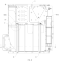
FIG. 1 is a perspective structural view of a base assembly for a dryer according to an embodiment of the present disclosure. -
FIG. 2 is a schematic plan view ofFIG. 1 . -
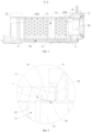
FIG. 3 is a schematic cross-sectional view taken along a line A-A inFIG. 2 . -
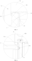
FIG. 4 is an enlarged view at B inFIG. 3 . -
FIG. 5 is an enlarged view at C inFIG. 3 . -
FIG. 6 is an enlarged view at D inFIG. 2 . -
FIG. 7 is a bottom view ofFIG. 2 . -
FIG. 8 is a top view ofFIG. 2 . -
FIG. 9 is a left side view ofFIG. 2 . -
FIG. 10 is a rear view ofFIG. 2 . -
FIG. 11 is a schematic structural view of a bottom plate and a connection base according to an embodiment of the present disclosure. -
FIG. 12 is a schematic cross-sectional view taken along a line E-E inFIG. 11 . -
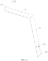
FIG. 13 is a schematic structural view of a first connection member according to an embodiment of the present disclosure. -
FIG. 14 is a schematic structural view of a second connection member according to an embodiment of the present disclosure. -
FIG. 15 is a schematic structural view of a third connection member according to an embodiment of the present disclosure. -
FIG. 16 is a partial structural schematic view of a base assembly for a dryer according to another embodiment of the present disclosure. -
FIG. 17 is a schematic cross-sectional view taken along a line F-F inFIG. 16 . -
FIG. 18 is a rear view ofFIG. 16 . - Reference Signs:
-
base assembly 100; -
air duct shell 1;cavity 1a; sealingrib 1b; positioninggroove 1c; firstair duct shell 11; secondair duct shell 12; - upper
air duct shell 13; lowerair duct shell 14; -
connection base 2;channel 2a; sealinggroove 2b; first protrudingrib 22; second protrudingrib 23; first positioningportion 24; -
door body 25; handle 26; first snappinghook 27; -
bottom plate 3;second positioning portion 31; first snappinghole 32; second snappinghole 33; - fixing
flange 34; first fixinghole 341; second fixinghole 35; -
support member 4; first snappinghole 41; first throughhole 42; second throughhole 43; -
connection member 5; -
first connection member 6; first abuttingsection 61; second snappinghole 611; firstvertical section 62; first snappingportion 621; secondvertical section 63;first connection hole 631; -
second connection member 7; second abuttingsection 71;second snapping hook 711; thirdvertical section 72; second snappingportion 721;second connection hole 722; -
third connection member 8; third abuttingsection 81;third snapping hook 811; fourthvertical section 82;third connection hole 821; -
liquid drainage separator 9;liquid drainage channel 91; -
evaporator 200; -
condenser 300. - The embodiments of the present disclosure are described in detail below, examples of which are illustrated in the accompanying drawings, where the same or similar reference numerals refer to the same or similar elements or elements having the same or similar functions throughout. The embodiments described below with reference to the accompanying drawings are exemplary and are only used to explain the present disclosure, rather than being as a limitation on the present disclosure.
- The following disclosure provides many different embodiments or examples for implementing different structures of the present disclosure. In order to simplify the present disclosure, components and arrangements of specific examples are described below. Of course, they are merely examples and are not intended to limit the present disclosure. Furthermore, the present disclosure may repeat reference signs and/or letters in different examples. This repetition is for the purpose of simplicity and clarity and does not in itself indicate a relationship between the various embodiments and/or arrangements as discussed. In addition, the present disclosure provides examples of various specific processes and materials. However, those of ordinary skill in the art will recognize applicability of other processes and/or the use of other materials.
- A
base assembly 100 for a dryer according to an embodiment of the present disclosure is described below with reference to the accompanying drawings. For example, the dryer may be a heat pump dryer. - Referring to
FIGS. 1 and2 , thebase assembly 100 for the dryer according to an embodiment of the present disclosure may include anair duct shell 1, aconnection base 2, abottom plate 3, asupport member 4 and at least oneconnection member 5. - Referring to
FIGS. 3 and 4 , theair duct shell 1 has acavity 1a where a heat exchanger is mounted. For example, the heat exchanger may be anevaporator 200 and acondenser 300. Theconnection base 2 has achannel 2a in communication with thecavity 1a, and is detachably disposed at a side of theair duct shell 1. - For example, in some examples, the
connection base 2 may be connected to theair duct shell 1 by a snapping-connection or a threaded fastener. In order to improve a sealing performance between theconnection base 2 and theair duct shell 1, a sealing ring may also be disposed between theconnection base 2 and theair duct shell 1. When theconnection base 2 is mounted at the side of theair duct shell 1 by the snapping-connection or the threaded fastener, the sealing ring is in a sealing-fit with theconnection base 2 and theair duct shell 1 at two axial sides thereof, respectively, to seal a connection between theconnection base 2 and theair duct shell 1. - It should be understood that by detachably arranging the
connection base 2 at the side of theair duct shell 1, theair duct shell 1 and theconnection base 2 can be designed separately, which is beneficial to reduce difficulty of mold design and production requirements. Further, since theair duct shell 1 and theconnection base 2 are separated components, theair duct shell 1 can be made of a different material from theconnection base 2, which facilitates application of a new material and reduction of material cost. - According to the base assembly for the dryer according to the embodiment of the present disclosure, by detachably arranging the
connection base 2 at the side of theair duct shell 1, theair duct shell 1 and theconnection base 2 can be designed separately, which is beneficial to reduce the difficulty of the mold design and the production requirements. Since theair duct shell 1 and theconnection base 2 are separated components, theair duct shell 1 can be made the different material from theconnection base 2, which facilitates the application of the new material and the reduction of the material cost. - In some embodiments of the present disclosure, as shown in
FIG. 3 , one of theconnection base 2 and theair duct shell 1 has a sealinggroove 2b, and the other has a sealingrib 1b. Here, theconnection base 2 may have the sealingrib 1b, and theair duct shell 1 may have the sealinggroove 2b in a sealing-fit with the sealingrib 1b. Alternatively, as shown inFIGS. 4 and5 , theconnection base 2 has the sealinggroove 2b, and theair duct shell 1 has the sealingrib 1b in a sealing-fit with the sealinggroove 2b. The sealinggroove 2b is engaged with the sealingrib 1b to seal a connection between theair duct shell 1 and theconnection base 2. - Therefore, by forming the sealing
groove 2b on one of theconnection base 2 and theair duct shell 1 and forming the sealingrib 1b on the other of theconnection base 2 and theair duct shell 1, the sealinggroove 2b can be engaged with the sealingrib 1b to seal the connection between theair duct shell 1 and theconnection base 2. Thus, the connection between theair duct shell 1 and theconnection base 2 has a good sealing performance, which is beneficial to ensure drying efficiency of the dryer. In addition, when assembling theair duct shell 1 and theconnection base 2, the sealinggroove 2b is engaged with the sealingrib 1b to realize a pre-positioning between theair duct shell 1 and theconnection base 2, which facilitates a fixing between theair duct shell 1 and theconnection base 2 and improving an assembling efficiency of thebase assembly 100. - In some embodiments of the present disclosure, as shown in
FIGS. 4 and5 , theair duct shell 1 has an air duct opening defined on a side thereof opposite to theconnection base 2, and theconnection base 2 has a channel opening defined on a side thereof opposite to theair duct shell 1. Here, the air duct opening is in communication with thecavity 1a, and the channel opening is in communication with thechannel 2a. One of the sealinggroove 2b and the sealingrib 1b extends in a circumferential direction of the air duct opening, and the other of the sealinggroove 2b and the sealingrib 1b extends in a circumferential direction of the channel opening. - For example, the
air duct shell 1 has a sealinggroove 2b extending into a ring shape in the circumferential direction of the air duct opening. Theconnection base 2 has a sealingrib 1b extending into a ring shape in the circumferential direction of the channel opening. In some embodiments, as shown inFIGS. 4 and5 , theair duct shell 1 has a sealingrib 1b extending into a ring shape in the circumferential direction of the air duct opening. Theconnection base 2 has a sealinggroove 2b extending into a ring shape in the circumferential direction of the channel opening. - Therefore, since one of the sealing
groove 2b and the sealingrib 1b extends in the circumferential direction of the air duct opening, and the other of the sealinggroove 2b and the sealingrib 1b extends in the circumferential direction of the channel opening, it is beneficial to further improve a sealing effect between thegroove 2b and the sealingrib 1b, thereby preventing air from leaking at the connection between theair duct shell 1 and theconnection base 2 and improving the drying efficiency of the dryer. - In some embodiments of the present disclosure, as shown in
FIGS. 4 and5 , one of theconnection base 2 and theair duct shell 1 has a first protrudingrib 22 and a second protrudingrib 23. The first protrudingrib 22 and the second protrudingrib 23 are spaced apart from each other in an arrangement direction (e.g., a front-rear direction as shown inFIG. 1 ) of theair duct shell 1 and theconnection base 2. The sealinggroove 2b is located between the first protrudingrib 22 and the second protrudingrib 23. It should be understood that the sealingrib 1b is partially engaged with the first protrudingrib 22 or the second protrudingrib 23 to further improve reliability of the pre-positioning-fit between theair duct shell 1 and theconnection base 2 through the engagement between the sealingrib 1b and the first protrudingrib 22 or the second protrudingrib 23, which is beneficial to further reduce difficulty of assembling between theconnection base 2 and theair duct shell 1. - For example, as shown in
FIG. 3 , theconnection base 2 has an annular first protrudingrib 22 and an annular second protrudingrib 23 on an outer peripheral wall thereof. The first protrudingrib 22 and the second protrudingrib 23 are spaced apart from each other in the front-rear direction. The sealinggroove 2b is disposed on the outer peripheral wall of theconnection base 2, and is located between the first protrudingrib 22 and the second protrudingrib 23. Theair duct shell 1 has anannular sealing rib 1b on an inner peripheral wall thereof. Front and rear side walls of the sealingrib 1b are adapted to abut with the first protrudingrib 22 and the second protrudingrib 23, respectively. - In some embodiments of the present disclosure, as shown in
FIGS. 4 and5 , the other of theconnection base 2 and theair duct shell 1 has apositioning groove 1c close to the sealingrib 1b, and one of the first protrudingrib 22 and the second protrudingrib 23 is inserted into thepositioning groove 1c. For example, as shown inFIG. 4 , theair duct shell 1a has apositioning groove 1c defined on the inner peripheral wall thereof and close to the sealingrib 1b, and the first protrudingrib 22 is inserted into thepositioning groove 1c. - It should be understood that, by forming the
positioning groove 1c to be adapted to be inserted into one of the first protrudingrib 22 and the second protrudingrib 23, on the one hand, it is beneficial to increase a sealing area between theconnection base 2 and theair duct shell 1, and improve the sealing effect between theconnection base 2 and theair duct shell 1. On the other hand, it is beneficial to further improve the reliability of the pre-positioning-fit between theair duct shell 1 and theconnection base 2, thereby further reducing the assembly difficulty between theconnection base 2 and theair duct shell 1. - In some embodiments of the present disclosure, as shown in
FIGS. 3 to 5 , the sealinggroove 2b is located on an outer wall surface of theconnection base 2, and the sealingrib 1b is located on an inner wall surface of theair duct shell 1. It should be understood that, since the sealinggroove 2b is located on the outer wall surface of theconnection base 2, and the sealingrib 1b is located on the inner wall surface of theair duct shell 1, when the sealingrib 1b is engaged with the sealinggroove 2b, theconnection base 2 and theair duct shell 1 can be positioned in the circumferential direction, and can be also positioned in the arrangement direction of theair duct shell 1 and theconnection base 2. Such a positioning is more reliable with simple structure, and thus processing difficulty and cost are low. - In some embodiments of the present disclosure, as shown in
FIGS. 7 and 8 , thebase assembly 100 further includes abottom plate 3. Theconnection base 2 and theair duct shell 1 are detachably disposed on thebottom plate 3, respectively. It should be understood that, in the related art, the connection base, the air duct shell and the bottom plate may be integrally formed into one piece, so that the base assembly has a relatively larger overall weight, relatively complicated process structure, as well as inconvenient disassembly, assembly and maintenance. In this disclosure, since thebottom plate 3, theconnection base 2 and theair duct shell 1 each have modular designs, thebottom plate 3, theconnection base 2 and theair duct shell 1 all have independently molded structures, a molding process of thebase assembly 100 can be simplified. These three structures can be replaced separately when repaired and mounted, and can be made of different materials, which is beneficial to reduce the weight of thebase assembly 100. - In some embodiments of the present disclosure, as shown in
FIG. 10 , theconnection base 2 has afirst positioning portion 24 provided on a bottom thereof, and thebottom plate 3 has asecond positioning portion 31 provided thereon. Thefirst positioning portion 24 is snapped with thesecond positioning portion 31 to position theconnection base 2. For example, as shown inFIGS. 11 and 12 , thefirst positioning portion 24 is formed as a positioning post, and thesecond positioning portion 31 is formed as a positioning hole. Therefore, a snapping-connection between theconnection base 2 and thebottom plate 3 can be realized, in which the structure is simple, and the connection is convenient. - In some embodiments, as shown in
FIG. 12 , theconnection base 2 has a plurality offirst positioning portions 24 provided on the bottom thereof, and thebottom plate 3 has a plurality ofsecond positioning portions 31 provided thereon. The plurality offirst positioning portions 24 is snapped with the plurality offirst positioning portions 24 in a one-to-one correspondence to position theconnection base 2. - In some embodiments of the present disclosure, as shown in
FIG. 1 , thebottom plate 3 has a fixingflange 34 provided on an edge thereof and bent upwardly. A side of theconnection base 2 is connected to the fixingflange 34 by a fastener. For example, as shown inFIG. 1 , two fixingflanges 34 are provided and located at left and right ends of thebottom plate 3, respectively. Each of the two fixingflanges 34 has afirst fixing hole 341 defined thereon. Theconnection base 2 has sides connected to the two fixingflanges 34 by fasteners, respectively, and abutting with the two fixingflanges 34. Therefore, the structure is simple, which is beneficial to enhance the reliability of the connection between thebottom plate 3 and theconnection base 2. - In some embodiments, as shown in
FIG. 10 , thebottom plate 3 also has asecond fixing hole 35 defined thereon, and the fastener passes through thesecond fixing hole 35 to be connected to the bottom of theconnection base 2. Therefore, it is beneficial to further improve the reliability of the connection between thebottom plate 3 and theconnection base 2. - In some embodiments of the present disclosure, as shown in
FIG. 8 , thebase assembly 100 also includes asupport member 4 having one end connected to theconnection base 2 and another end connected to thebottom plate 3. For example, thesupport member 4 may be formed into an elongated strip, and the base has afirst snapping hook 27 dispose thereon. Thesupport member 4 has afirst snapping hole 41 defined at one end thereof and engaged with thefirst snapping hook 27. Further, thesupport member 4 also has a first throughhole 42 defined on one end thereof. A threaded fastener passes through the first throughhole 42 to fix the one end of thesupport member 4 to a base. Thesupport member 4 has a second throughhole 43 defined at the other end thereof. A threaded fastener passes through the second throughhole 43 to fix the other end of thesupport member 4 on thebottom plate 3. - In this way, it is beneficial to prevent the
connection base 2 from being inclined relative to thebottom plate 3 in a subsequent installation, which is beneficial to further improve the reliability of the connection between theconnection base 2 and thebottom plate 3. In some embodiments, twosupport members 4 may be provided and located on the left and right sides of theconnection base 2, respectively. - In some examples, as shown in
FIG. 1 , theconnection base 2 has an access opening, and adoor body 25 that can be opened and closed is disposed at the access opening, Thedoor body 25 has ahandle 26 to facilitate opening and closing thedoor body 25 by a user. - In some embodiments, as shown in
FIG. 1 , thebottom plate 3 is a metal piece, and theconnection base 2 is configured as a plastic piece formed separately from thebottom plate 3. For example, thebottom plate 3 may be an iron plate or a stainless-steel plate. Therefore, on the one hand, since thebottom plate 3 is the metal piece, it is beneficial to ensure a structural strength of thebase assembly 100. On the other hand, since theconnection base 2 is configured as the plastic piece formed separately from thebottom plate 3, it is beneficial to reduce the overall weight of thebase assembly 100. - In some embodiments of the present disclosure, as shown in
FIG. 1 , theair duct shell 1 is fixedly mounted on thebottom plate 3 by at least oneconnection member 5. Therefore, the structure is simple, which is beneficial to reduce the difficulty of assembling and improve the assembling efficiency. - In some embodiments of the present disclosure, as shown in
FIG. 1 , the at least oneconnection member 5 is detachably connected to thebottom plate 3 at both ends thereof, respectively, and at least a part of theair duct shell 1 is located between a middle part of the at least oneconnection member 5 and thebottom plate 3. Therefore, while reducing the difficulty of assembling, it is beneficial to realize reliable fixing of theair duct shell 1 and reduce the damage to theair duct shell 1. For example, as shown inFIG. 13 , the at least oneconnection member 5 includes afirst connection member 6. Thefirst connection member 6 is detachably connected to thebottom plate 3 at both ends thereof, respectively, and at least a part of theair duct shell 1 is located between a middle of thefirst connection member 6 and thebottom plate 3. - In some embodiments, as shown in
FIG. 1 , the at least oneconnection member 5 matches with an outer contour of theair duct shell 1. Therefore, it is beneficial to increase the engagement area between the at least oneconnection member 5 and theair duct shell 1, thereby further realizing the reliable fixing of theair duct shell 1. - In some embodiments of the present disclosure, as shown in
FIG. 1 , theair duct shell 1 is configured as a thermal insulation member formed separately from thebottom plate 3. For example, theair duct shell 1 may be a foamed piece such as a foamed plastic and a foamed rubber. Therefore, it is beneficial to improve a thermal insulation effect of theair duct shell 1 whiling reducing the weight of theair duct shell 1. - In some embodiments of the present disclosure, as shown in
FIGS. 1 and13 , the at least oneconnection member 5 includes a first abuttingsection 61, a firstvertical section 62 and a secondvertical section 63. The first abuttingsection 61 is located above thebottom plate 3 and spaced apart from thebottom plate 3. Each of the firstvertical section 62 and the secondvertical section 63 has one end connected to thebottom plate 3, respectively, and another end connected to both ends of the first abuttingsection 61, respectively. - Here, the first abutting
section 61 is engaged with a top wall of theair duct shell 1, and the firstvertical section 62 and/or the secondvertical section 63 is engaged with a side wall of theair duct shell 1. In other words, one of the firstvertical section 62 and the secondvertical section 63 may be engaged with a side wall of theair duct shell 1, or the firstvertical section 62 and the secondvertical section 63 may be engaged with opposite side walls of theair duct shell 1, respectively. Therefore, it is beneficial to increase an engagement area between the at least oneconnection member 5 and theair duct shell 1, and further realize the reliable fixing of theair duct shell 1. In addition, the at least oneconnection member 5 has a simple structure and low cost. - In some embodiments of the present disclosure, as shown in
FIG. 13 , the at least oneconnection member 5 has one end snapped with thebottom plate 3 and another end connected to thebottom plate 3 by a threaded fastener. It should be understood that, when theair duct shell 1 is fixed on thebottom plate 3 by the at least oneconnection member 5, the one end of the at least oneconnection member 5 can be snapped with thebottom plate 3 first, and then the other end of the at least oneconnection member 5 can be connected to thebottom plate 3 by the threaded fastener. Thus, the connection is convenient and the assembly effect is high, thereby improving the reliability of fixing of theair duct shell 1. - In some embodiments of the present disclosure, as shown in
FIG. 1 , the at least oneconnection member 5 includes a plurality of connection members arranged at intervals in a length direction of theair duct shell 1. For example, twoconnection members 5 are provided and spaced apart from each other in the length direction of theair duct shell 1. Therefore, it is beneficial to further realize the reliable fixing of theair duct shell 1. - In some embodiments of the present disclosure, as shown in
FIG. 1 , the at least oneconnection member 5 includes afirst connection member 6 having two ends detachably connected to thebottom plate 3, respectively. At least a part of theair duct shell 1 is located between a middle part of thefirst connection member 6 and thebottom plate 3. Therefore, while reducing the difficulty of assembling, it is beneficial to realize the reliable fixing of theair duct shell 1 and reduce the damage to theair duct shell 1. For example, a plurality offirst connection members 6 may be provided and arranged at intervals in the length direction of the firstair duct shell 11. - Further, as shown in
FIG. 13 , thefirst connection member 6 includes a first abuttingsection 61, a firstvertical section 62 and a secondvertical section 63. The first abuttingsection 61 is located above thebottom plate 3 and space apart from thebottom plate 3. Each of the firstvertical section 62 and the secondvertical section 63 has one end connected to thebottom plate 3, respectively, and another end connected to both ends of the first abuttingsection 61, respectively. - The first abutting
section 61 is engaged with the top wall of theair duct shell 1, and the firstvertical section 62 and/or the secondvertical section 63 are/is engaged with the side wall of theair duct shell 1. In other words, one of the firstvertical section 62 and the secondvertical section 63 may be engaged with one side wall of theair duct shell 1, or the firstvertical section 62 and the secondvertical section 63 may be engaged with the opposite side walls of theair duct shell 1, respectively. Therefore, it is beneficial to increase an engagement area of theconnection member 5 and theair duct shell 1, and further realize the reliable fixing of theair duct shell 1. In addition, thefirst connection member 6 has a simple structure and low cost. - In some embodiments of the present disclosure, as shown in
FIG. 13 , thefirst connection member 6 has one end snapped with thebottom plate 3, and another end connected to thebottom plate 3 by a threaded fastener. For example, the firstvertical section 62 has afirst snapping portion 621 on a free end thereof, and thebottom plate 3 has a first snapping hole 32 (refer toFIG. 10 ) engaged with thefirst snapping portion 621. The secondvertical section 63 has afirst connection hole 631 defined thereon. Thefirst connection hole 631 is adapted for a threaded fastener to pass therethrough. It should be understood that, when theair duct shell 1 is fixed on thebottom plate 3 by the at least oneconnection member 5, the one end of the at least oneconnection member 5 can be snapped with thebottom plate 3 first, and then the other end of the at least oneconnection member 5 can be connected to thebottom plate 3 by the threaded fastener. Thus, the connection is convenient, and the assembly effect is high, thereby improving the reliability of fixing of theair duct shell 1. - In some embodiments of the present disclosure, as shown in
FIG. 1 , a plurality offirst connection members 6 is provided and arranged at intervals in the length direction of theair duct shell 1. Therefore, it is beneficial to further realize the reliable fixing of theair duct shell 1. - In some embodiments of the present disclosure, as shown in
FIG. 1 , theair duct shell 1 includes a firstair duct shell 11 and a secondair duct shell 12 in communication with the firstair duct shell 11. Here, the firstair duct shell 11 is at least partially fixed on thebottom plate 3 by thefirst connection member 6. The at least oneconnection member 5 also includes asecond connection member 7. Thesecond connection member 7 has one end connected to thefirst connection member 6, and another end detachably connected to thebottom plate 3. The secondair duct shell 12 is at least partially fixed on thebottom plate 3 by thesecond connection member 7. - Therefore, fixing of the first
air duct shell 11 can be realized by thefirst connection member 6, and fixing of the secondair duct shell 12 can be realized by thesecond connection member 7. As a result, it is beneficial to further improve the effect of fixing of theair duct shell 1. Meanwhile, thesecond connection member 7 is connected to thefirst connection member 6 at one end thereof and is detachably connected to thebottom plate 3 at the other end thereof, the secondair duct shell 12 is at least partially fixed to thebottom plate 3 by thesecond connection member 7. Thus, it is beneficial to simplify a structure of thesecond connection member 7, thereby easily realizing the fixing of thesecond connection member 7. - Further, as shown in
FIG. 14 , thesecond connection member 7 includes a second abuttingsection 71 and a thirdvertical section 72. The secondabutting section 71 is located above thebottom plate 3 and spaced apart from thebottom plate 3. The thirdvertical section 71 has one end connected to thebottom plate 3, and another end connected to the second abuttingsection 71. The secondabutting section 71 is engaged with a top wall of the secondair duct shell 12, and the thirdvertical section 72 is engaged with a side wall of the secondair duct shell 12. - Therefore, it is beneficial to increase an engagement area between the
second connection member 7 and the secondair duct shell 12, and further realize the reliable fixing of theair duct shell 1. Thus, thesecond connection member 7 has simple structure and lower cost. - In some embodiments of the present disclosure, as shown in
FIGS. 1 and6 , thesecond connection member 7 has one end snapped to thefirst connection member 6, and another end detachably connected to thebottom plate 3. For example, as shown inFIG. 6 , thesecond connection member 7 has asecond snapping hook 711 at the one end thereof, and thefirst connection member 6 has asecond snapping hole 611 defined thereon and adapted to be engaged with thesecond snapping hook 711. Thesecond connection member 7 has another end connected to thebottom plate 3 through a snapping-connection or a threaded fastener. Therefore, the structure is simple, and the assembly and disassembly of thesecond connection member 7 are facilitated. Thus, the fixing of thesecond connection member 7 to the secondair duct shell 12 is reliable. - In some embodiments, as shown in
FIG. 14 , the thirdvertical section 72 has asecond snapping portion 721 provided at a free end thereof, and thebottom plate 3 has asecond snapping hole 33 defined thereon and engaged with the second snapping portion 721 (as shown inFIG. 9 ). The thirdvertical section 72 of thesecond connection member 7 also has asecond connection hole 722 defined thereon. A threaded fastener passes through thesecond connection hole 722 to be connected to a casing of the dryer to fix the thirdvertical section 72 to the casing of the dryer. Thus, it is beneficial to further improve fixing effect of the secondair duct shell 12 by thesecond connection member 7. - In some embodiments of the present disclosure, as shown in
FIGS. 1 and15 , the at least oneconnection member 5 also includes athird connection member 8 spaced apart from thesecond connection member 7 in a length direction of the secondair duct shell 12. Thethird connection member 8 has one end detachably connected to thebottom plate 3, and another end connected to an external structure. For example, the external structure may be the casing of the dryer. Thethird connection member 8 has athird connection hole 821 defined at one end thereof, and a threaded fastener passes through thethird connection hole 821 to fix the one end of thethird connection member 8 to thebottom plate 3. Further, thethird connection member 8 has another end detachably connected to the casing of the dryer. - Therefore, by arranging the
second connection member 7 and thethird connection member 8, the secondair duct shell 12 has good fixing effect, which ensures a reliable operation of theair duct shell 1. - In some embodiments of the present disclosure, as shown in
FIG. 15 , thethird connection member 8 includes a thirdabutting section 81 and a fourthvertical section 82. The thirdabutting section 81 is located above thebottom plate 3 and spaced apart from thebottom plate 3. The fourthvertical section 82 has one end connected to thebottom plate 3, and another end connected to the third abuttingsection 81. The thirdabutting section 81 is engaged with the top wall of the secondair duct shell 12, and the fourthvertical section 82 is engaged with the side wall of the secondair duct shell 12. For example, the third abuttingsection 81 has athird snapping hook 811 at a free end thereof and adapted to be engaged with the casing of the dryer. Therefore, it is beneficial to increase an engagement area of thethird connection member 8 and the secondair duct shell 12, which further realizes the reliable fixing of theair duct shell 1. In addition, thethird connection member 8 has simple structure, low cost, and reliable connection. - In some embodiments of the present disclosure, as shown in
FIG. 1 , the length direction of the firstair duct shell 11 is perpendicular to the length direction of the secondair duct shell 12. For example, the firstair duct shell 11 and the secondair duct shell 12 are arranged in the front-rear direction, and the firstair duct shell 11 is perpendicular to the secondair duct shell 12. Therefore, it is beneficial to reduce an overall space occupation of the firstair duct shell 11 and the secondair duct shell 12, thereby facilitating reduction of the space occupation of theair duct shell 1. - In some examples, as shown in
FIG. 3 , aliquid drainage separator 9 is disposed in the firstair duct shell 11. Theliquid drainage separator 9 has a liquid guide groove with an inlet and an outlet located at two ends in a length direction (the front-rear direction as shown inFIG. 1 ) thereof. Theliquid drainage separator 9 also has a liquid distribution groove located on at least one side in a width direction (a left-right direction as shown inFIG. 1 ) thereof. The liquid distribution groove is in communication with the liquid guide groove through a liquid passage opening. Aliquid drainage channel 91 for a condensate is defined by the liquid guide groove, the liquid distribution groove, and an inner bottom wall of thecavity 1a. Therefore, when a negative pressure is generated in an air duct, the condensate flowing back at the outlet of the liquid guide groove can flow to the liquid guide groove and the liquid distribution groove respectively. In this way, on the one hand, a liquid distribution can be provided to reduce hydraulic pressure, and on the other hand, it is possible to increase a backflow path of the condensate, which is beneficial to prevent the condensate from flowing back into the air duct, thereby improving drying efficiency. - In some examples, referring to
FIG. 1 , theair duct shell 1 includes an upperair duct shell 13 and a lowerair duct shell 14 that are connected to each other. Thecavity 1a of theair duct shell 1 is defined by the upperair duct shell 13 and the lowerair duct shell 14. A part of the sealingrib 1b is formed on an inner peripheral wall of the upperair duct shell 13, and the remaining part of the sealingrib 1b is formed on the lowerair duct shell 14. The sealingrib 1b is defined by the upperair duct shell 13 and the lowerair duct shell 14 together. When assembling thebase assembly 100, theconnection base 2 may be mounted on thebottom plate 3 first, then the lowerair duct shell 14 is brought into the sealing-fit with theconnection base 2, and then the upperair duct shell 13 is brought into the sealing-fit with theconnection base 2, to achieve the pre-positioning of theair duct shell 1. Then, the two ends of thesupport member 4 are fixed to theconnection base 2 and theair duct shell 1, respectively, to realize the fixing connection between theconnection base 2 and theair duct shell 1, and prevent the connectingseat 2 from being inclined relative to theair duct shell 1 before supporting other components in the subsequent installation. Finally, thefirst connection member 6, thesecond connection member 7 and thethird connection member 8 are mounted, respectively, to fix theair duct shell 1 on thebottom plate 3. Thus, the assembly of thebase assembly 100 is completed. As a result, thebase assembly 100 is simply assembled, and has good sealing performance and light weight. - In other embodiments of the present disclosure, as shown in
FIG. 16 , at least oneconnection member 5 is a threaded fastener, by which theair duct shell 1 and thebottom plate 3 are connected to each other. For example, as shown inFIGS. 17 and18 , the at least oneconnection member 5 includes a plurality ofconnection members 5, each of which is a threaded fastener. Theair duct shell 1 and thebottom plate 3 are connected to each other by the plurality of threaded fasteners. Therefore, the connection between theair duct shell 1 and thebottom plate 3 can be made reliable, and the cost is low. - In some embodiments, as shown in
FIGS. 17 and18 , theair duct shell 1 includes an upperair duct shell 13 and a lowerair duct shell 14 that are connected to each other. Thecavity 1a of theair duct shell 1 is defined by the upperair duct shell 13 and the lowerair duct shell 14 together. Each of the plurality ofconnection members 5 is a screw. When theair duct shell 1 is mounted on thebottom plate 3, the lowerair duct shell 14 may be placed on thebottom plate 3 first, and then the plurality of screws passes through the lowerair duct shell 14 and thebottom plate 3 from top to bottom, respectively, to fix the lowerair duct shell 14 on thebottom plate 3. Finally, the upperair duct shell 13 is mounted on the lowerair duct shell 14. - A dryer according to an embodiment of the present disclosure includes the
base assembly 100 for the dryer according to the above embodiments of the present disclosure. - In the dryer according to the embodiments of the present disclosure, by arranging the
base assembly 100 for the dryer according to the embodiments of the present disclosure as described above, theair duct shell 1 and theconnection base 2 can be designed separately, which is beneficial to reduce the difficulty of mold design and production requirements. Further, since the air duct shell and connection base are separated components, the air duct shell can be made the different material from the connection base, which facilitates an application of a new material and reduction of material cost. - Other structures and operations of the dryer according to the embodiments of the present disclosure are known to those of ordinary skill in the art, and will not be described in detail herein.
- In the specification, it is to be understood that terms such as "central," "length," "width," "thickness," "upper," "lower," "front," "rear," "left," "right," "vertical," "horizontal," "top," "bottom," "inner," "outer," "axial," "radial," "circumferential," and the like should be construed to refer to the orientation or direction as shown in the drawings, which are merely for the convenience of description and simplifying the description, rather than indicating or implying that the associated apparatuses or elements must have a specific orientation, and be constructed and operate in a specific orientation, and therefore should not be construed as a limitation on the present disclosure..
- In addition, terms such as "first" and "second" are used herein for purposes of description and are not intended to indicate or imply relative importance or significance or to imply the number of indicated technical features. Thus, the feature associated with "first" and "second" may indicate or imply that one or more of these features are included. In the description of the present disclosure, "a plurality of" means two or more than two, unless specified otherwise.
- In the present disclosure, unless specified or limited otherwise, the terms "mounted," "connected," "coupled," "fixed" and the like should be understood broadly, and may be, for example, fixed connections, detachable connections, or integral connections; it may also be a mechanical connection or an electrical connection or a communication with each other; it may also be a direct connection or an indirect connection through an intermediating structure; it may also be an inner communication of two elements or an interaction relationship between the two elements. For those of ordinary skill in the art, the specific meanings of the above terms in the present disclosure can be understood according to specific situations.
- Reference throughout this specification to "an embodiment," "some embodiments," "an example," "specific examples" or "some examples" means that a particular feature, structure, material, or characteristic described in connection with the embodiment or example is included in at least one embodiment or example of the present disclosure. Thus, the appearances of the above phrases throughout this specification are not necessarily referring to the same embodiment or example of the present disclosure. Furthermore, the particular features, structures, materials, or characteristics as described may be combined in one or more embodiments or examples in any suitable manner. Furthermore, those skilled in the art may combine the different embodiments or examples described in this specification, as well as the features of the different embodiments or examples with each other without conflicting each other.
Claims (12)
- A base assembly (100) for a dryer, the base assembly comprising: an air duct shell (1) having a cavity (1a), wherein the cavity (1a) is suitable for accommodating a heat exchanger; and a connection base (2) having a channel (2a) in communication with the cavity (1a), the connection base (2) being detachably disposed at a side of the air duct shell (1),characterised in that one of the connection base (2) and the air duct shell (1) has a sealing groove (2b), and the other of the connection base (2) and the air duct shell (1) has a sealing rib (1b) engaged in the sealing groove (2b) to seal a connection between the air duct shell (1) and the connection base (2);wherein the one of the connection base (2) and the air duct shell (1) has a first protruding rib (22) and a second protruding rib (23) that are spaced apart from each other in an arrangement direction of the air duct shell (1) and the connection base (2); and the sealing groove (2b) is located between the first protruding rib (22) and the second protruding rib (23); andwherein the other of the connection base (2) and the air duct shell (1) has a positioning groove (1c) close to the sealing rib (1b); and one of the first protruding rib (22) and the second protruding rib (23) is inserted into the positioning groove (1c).
- The base assembly (100) for the dryer according to claim 1, wherein: the air duct shell (1) has an air duct opening defined on a side thereof opposite to the connection base (2) and in communication with the cavity (1a); the connection base (2) has a channel opening defined on a side thereof opposite to the air duct shell (1) and in communication with the channel (2a); and one of the sealing groove (2b) and the sealing rib (1b) extends in a circumferential direction of the air duct opening, and the other of the sealing groove (2b) and the sealing rib (1b) extends in a circumferential direction of the channel opening.
- The base assembly (100) for the dryer according to claim 1, wherein: the sealing groove (2b) is located on an outer wall surface of the connection base (2); and the sealing rib (1b) is located on an inner wall surface of the air duct shell (1).
- The base assembly (100) for the dryer according to any one of claims 1 to 3, further comprising a bottom plate (3), wherein the connection base (2) and the air duct shell (1) are detachably disposed on the bottom plate (3), respectively.
- The base assembly (100) for the dryer according to claim 4, wherein: the connection base (2) has a first positioning portion (24) provided on a bottom thereof; and the bottom plate (3) has a second positioning portion (31) provided thereon, the first positioning portion (24) being snapped with the second positioning portion (31) to position the connection base (2).
- The base assembly (100) for the dryer according to claim 4, wherein: the bottom plate (3) has a fixing flange (34) provided on an edge thereof and bent upwardly; and a side of the connection base (2) is connected to the fixing flange (34) by a fastener.
- The base assembly (100) for the dryer according to claim 4, wherein:the base assembly (100) further comprises a support member (4) having one end connected to the connection base (2) and another end connected to the bottom plate (3); orthe bottom plate (3) is a metal piece, and the connection base (2) is configured as a plastic piece formed separately from the bottom plate (3).
- The base assembly (100) for the dryer according to any one of claims 4 to 7, wherein the air duct shell is fixedly mounted on the bottom plate (3) by at least one connection member (5).
- The base assembly (100) for the dryer according to claim 8, wherein: the at least one connection member (5) has two ends detachably connected to the bottom plate (3), respectively; and at least a part of the air duct shell (1) is located between a middle part of the at least one connection member (5) and the bottom plate (3).
- The base assembly (100) for the dryer according to claim 9, wherein:the at least one connection member matches with an outer counter of the air duct shell (1); orthe at least one connection member (5) comprises: a first abutting section (61) located above the bottom plate (3) and spaced apart from the bottom plate (3); a first vertical section; and a second vertical section, wherein: the bottom plate (3) is connected to one end of the first vertical section and one end of the second vertical section, respectively; the first abutting section (61) is connected to another end of the first vertical section and another end of the second vertical section, respectively; the first abutting section (61) is engaged with a top wall of the air duct shell (1); and the first vertical section and/or the second vertical section is engaged with a side wall of the air duct shell (1); orthe at least one connection member (5) has one end snapped with the bottom plate (3), and another end connected to the bottom plate (3) by a threaded fastener.
- The base assembly (100) for the dryer according to any one of claims 8 to 10, wherein the at least one connection member (5) comprises a plurality of connection members arranged at intervals in a length direction of the air duct shell (1).
- A dryer, comprising the base assembly (100) for the dryer according to any one of claims 1 to 11.
Applications Claiming Priority (2)
| Application Number | Priority Date | Filing Date | Title |
|---|---|---|---|
| CN202010315376.7A CN113529379B (en) | 2020-04-21 | 2020-04-21 | Base assembly for clothes dryer and clothes dryer with same |
| PCT/CN2020/097512 WO2021212644A1 (en) | 2020-04-21 | 2020-06-22 | Base assembly for dryer and dryer provided with same |
Publications (4)
| Publication Number | Publication Date |
|---|---|
| EP4137631A1 EP4137631A1 (en) | 2023-02-22 |
| EP4137631A4 EP4137631A4 (en) | 2023-10-25 |
| EP4137631B1 true EP4137631B1 (en) | 2024-07-24 |
| EP4137631C0 EP4137631C0 (en) | 2024-07-24 |
Family
ID=78123763
Family Applications (1)
| Application Number | Title | Priority Date | Filing Date |
|---|---|---|---|
| EP20932400.3A Active EP4137631B1 (en) | 2020-04-21 | 2020-06-22 | Base assembly for dryer and dryer provided with same |
Country Status (3)
| Country | Link |
|---|---|
| EP (1) | EP4137631B1 (en) |
| CN (1) | CN113529379B (en) |
| WO (1) | WO2021212644A1 (en) |
Family Cites Families (20)
| Publication number | Priority date | Publication date | Assignee | Title |
|---|---|---|---|---|
| CN2357034Y (en) * | 1998-11-06 | 2000-01-05 | 中山威力集团公司 | Internal circulation environment-friendly clothes dryer |
| KR20070082376A (en) * | 2006-02-16 | 2007-08-21 | 엘지전자 주식회사 | Drum-type washing machine with dryer |
| TWI391548B (en) * | 2008-05-12 | 2013-04-01 | Toshiba Kk | Laundry dryer |
| JP5075731B2 (en) * | 2008-05-12 | 2012-11-21 | 株式会社東芝 | Washing and drying machine |
| CN101761510A (en) * | 2008-12-24 | 2010-06-30 | 珠海格力电器股份有限公司 | Volute and clothes dryer |
| CN202543670U (en) * | 2012-02-15 | 2012-11-21 | 上海日立电器有限公司 | Return air structure of heat pump type washing and drying machine |
| US9261120B2 (en) * | 2012-11-30 | 2016-02-16 | Illinois Tool Works Inc. | Clips for coupling devices to support members extending between structural members |
| EP3090095B1 (en) * | 2013-12-30 | 2017-11-22 | Electrolux Appliances Aktiebolag | Laundry treatment apparatus with fluff filter washing arrangement |
| WO2015101386A1 (en) * | 2013-12-30 | 2015-07-09 | Electrolux Appliances Aktiebolag | Laundry treatment apparatus with fluff filter washing arrangement |
| CN204006369U (en) * | 2014-06-06 | 2014-12-10 | 艾美特电器(深圳)有限公司 | a dehumidifier |
| CN204151574U (en) * | 2014-10-14 | 2015-02-11 | 松下知识产权经营株式会社 | For box component for washing agent and the washing machine of washing machine |
| PL3124684T3 (en) * | 2015-07-27 | 2021-12-06 | Electrolux Appliances Aktiebolag | Laundry dryer |
| CN205775464U (en) * | 2016-05-19 | 2016-12-07 | 无锡小天鹅股份有限公司 | The spiral case of dryer and the dryer with it |
| CN105937171B (en) * | 2016-05-31 | 2018-10-23 | 无锡小天鹅股份有限公司 | Heat pump system and dryer or washing-drying integral machine with it |
| CN106087362B (en) * | 2016-05-31 | 2018-08-28 | 无锡小天鹅股份有限公司 | Heat pump mounting box and heat pump clothes dryer or heat pump washing-drying integral machine |
| CN106367932A (en) * | 2016-09-30 | 2017-02-01 | 无锡小天鹅股份有限公司 | Clothes dryer |
| JP6871564B2 (en) * | 2016-12-26 | 2021-05-12 | 青島海爾洗衣机有限公司QingDao Haier Washing Machine Co.,Ltd. | Washing and drying machine |
| CN106948147B (en) * | 2017-04-01 | 2019-07-19 | 无锡小天鹅股份有限公司 | Heat pump assembly for washing-drying integral machine and the washing-drying integral machine with it |
| CN109487507B (en) * | 2017-09-13 | 2021-05-25 | 青岛海尔洗涤电器有限公司 | A clothing treatment device |
| CN110857521B (en) * | 2018-08-24 | 2024-03-08 | 无锡飞翎电子有限公司 | Base assembly for clothes dryer, condensation drying system and clothes dryer |
-
2020
- 2020-04-21 CN CN202010315376.7A patent/CN113529379B/en active Active
- 2020-06-22 WO PCT/CN2020/097512 patent/WO2021212644A1/en not_active Ceased
- 2020-06-22 EP EP20932400.3A patent/EP4137631B1/en active Active
Also Published As
| Publication number | Publication date |
|---|---|
| EP4137631A4 (en) | 2023-10-25 |
| EP4137631C0 (en) | 2024-07-24 |
| CN113529379B (en) | 2022-12-20 |
| EP4137631A1 (en) | 2023-02-22 |
| CN113529379A (en) | 2021-10-22 |
| WO2021212644A1 (en) | 2021-10-28 |
Similar Documents
| Publication | Publication Date | Title |
|---|---|---|
| CN104930702A (en) | Heat pump water heater | |
| EP4137631A1 (en) | Base assembly for dryer and dryer provided with same | |
| EP4098794B1 (en) | Base assembly for clothes dryer, and clothes dryer having same | |
| CN222187124U (en) | Air duct assembly, indoor unit and heating ventilation equipment | |
| CN111622994A (en) | Bladeless fan | |
| CN217900168U (en) | dehumidifier | |
| CN211977036U (en) | Cabinet air conditioner and air conditioner | |
| CN224002942U (en) | Assembly structure and air conditioner | |
| CN211854216U (en) | Floor type air conditioner indoor unit and air conditioner | |
| CN210832514U (en) | Base assembly, air conditioner indoor unit and air conditioner | |
| CN222785829U (en) | Motor components and air conditioners | |
| CN223271353U (en) | Air conditioner | |
| CN206071918U (en) | Fan assembly and the baking box with which | |
| CN223388670U (en) | Air conditioner | |
| AU2023210633B2 (en) | Electric box of heat-pump water heater and heat-pump water heater | |
| CN223985446U (en) | Air duct panels, air duct components, cabinet liner components and refrigeration equipment | |
| US12287112B2 (en) | Middle air duct support member and air conditioner | |
| CN217545726U (en) | Motor and washing machine | |
| CN215571143U (en) | Casing and air conditioner | |
| EP3822548B1 (en) | Ceiling machine | |
| CN213272909U (en) | Sterilization module and air conditioner for air conditioner | |
| CN223854480U (en) | Blowing device | |
| CN217468835U (en) | Embedded part and refrigeration equipment | |
| CN213273117U (en) | Panel assembly of air conditioner and air conditioner with same | |
| CN224033902U (en) | Air inlet frame assembly and air conditioner |
Legal Events
| Date | Code | Title | Description |
|---|---|---|---|
| STAA | Information on the status of an ep patent application or granted ep patent |
Free format text: STATUS: THE INTERNATIONAL PUBLICATION HAS BEEN MADE |
|
| PUAI | Public reference made under article 153(3) epc to a published international application that has entered the european phase |
Free format text: ORIGINAL CODE: 0009012 |
|
| STAA | Information on the status of an ep patent application or granted ep patent |
Free format text: STATUS: REQUEST FOR EXAMINATION WAS MADE |
|
| 17P | Request for examination filed |
Effective date: 20221118 |
|
| AK | Designated contracting states |
Kind code of ref document: A1 Designated state(s): AL AT BE BG CH CY CZ DE DK EE ES FI FR GB GR HR HU IE IS IT LI LT LU LV MC MK MT NL NO PL PT RO RS SE SI SK SM TR |
|
| DAV | Request for validation of the european patent (deleted) | ||
| DAX | Request for extension of the european patent (deleted) | ||
| A4 | Supplementary search report drawn up and despatched |
Effective date: 20230921 |
|
| RIC1 | Information provided on ipc code assigned before grant |
Ipc: D06F 39/12 20060101ALN20230915BHEP Ipc: D06F 58/24 20060101ALN20230915BHEP Ipc: D06F 58/20 20060101AFI20230915BHEP |
|
| GRAP | Despatch of communication of intention to grant a patent |
Free format text: ORIGINAL CODE: EPIDOSNIGR1 |
|
| STAA | Information on the status of an ep patent application or granted ep patent |
Free format text: STATUS: GRANT OF PATENT IS INTENDED |
|
| RIC1 | Information provided on ipc code assigned before grant |
Ipc: D06F 39/12 20060101ALN20240322BHEP Ipc: D06F 58/24 20060101ALN20240322BHEP Ipc: D06F 58/20 20060101AFI20240322BHEP |
|
| INTG | Intention to grant announced |
Effective date: 20240417 |
|
| GRAS | Grant fee paid |
Free format text: ORIGINAL CODE: EPIDOSNIGR3 |
|
| GRAA | (expected) grant |
Free format text: ORIGINAL CODE: 0009210 |
|
| STAA | Information on the status of an ep patent application or granted ep patent |
Free format text: STATUS: THE PATENT HAS BEEN GRANTED |
|
| AK | Designated contracting states |
Kind code of ref document: B1 Designated state(s): AL AT BE BG CH CY CZ DE DK EE ES FI FR GB GR HR HU IE IS IT LI LT LU LV MC MK MT NL NO PL PT RO RS SE SI SK SM TR |
|
| REG | Reference to a national code |
Ref country code: GB Ref legal event code: FG4D |
|
| REG | Reference to a national code |
Ref country code: CH Ref legal event code: EP |
|
| REG | Reference to a national code |
Ref country code: IE Ref legal event code: FG4D Ref country code: DE Ref legal event code: R096 Ref document number: 602020034677 Country of ref document: DE |
|
| U01 | Request for unitary effect filed |
Effective date: 20240822 |
|
| U07 | Unitary effect registered |
Designated state(s): AT BE BG DE DK EE FI FR IT LT LU LV MT NL PT RO SE SI Effective date: 20240902 |
|
| PG25 | Lapsed in a contracting state [announced via postgrant information from national office to epo] |
Ref country code: NO Free format text: LAPSE BECAUSE OF FAILURE TO SUBMIT A TRANSLATION OF THE DESCRIPTION OR TO PAY THE FEE WITHIN THE PRESCRIBED TIME-LIMIT Effective date: 20241024 |
|
| PG25 | Lapsed in a contracting state [announced via postgrant information from national office to epo] |
Ref country code: PL Free format text: LAPSE BECAUSE OF FAILURE TO SUBMIT A TRANSLATION OF THE DESCRIPTION OR TO PAY THE FEE WITHIN THE PRESCRIBED TIME-LIMIT Effective date: 20240724 Ref country code: GR Free format text: LAPSE BECAUSE OF FAILURE TO SUBMIT A TRANSLATION OF THE DESCRIPTION OR TO PAY THE FEE WITHIN THE PRESCRIBED TIME-LIMIT Effective date: 20241025 |
|
| PG25 | Lapsed in a contracting state [announced via postgrant information from national office to epo] |
Ref country code: IS Free format text: LAPSE BECAUSE OF FAILURE TO SUBMIT A TRANSLATION OF THE DESCRIPTION OR TO PAY THE FEE WITHIN THE PRESCRIBED TIME-LIMIT Effective date: 20241124 |
|
| PG25 | Lapsed in a contracting state [announced via postgrant information from national office to epo] |
Ref country code: HR Free format text: LAPSE BECAUSE OF FAILURE TO SUBMIT A TRANSLATION OF THE DESCRIPTION OR TO PAY THE FEE WITHIN THE PRESCRIBED TIME-LIMIT Effective date: 20240724 |
|
| PG25 | Lapsed in a contracting state [announced via postgrant information from national office to epo] |
Ref country code: ES Free format text: LAPSE BECAUSE OF FAILURE TO SUBMIT A TRANSLATION OF THE DESCRIPTION OR TO PAY THE FEE WITHIN THE PRESCRIBED TIME-LIMIT Effective date: 20240724 Ref country code: RS Free format text: LAPSE BECAUSE OF FAILURE TO SUBMIT A TRANSLATION OF THE DESCRIPTION OR TO PAY THE FEE WITHIN THE PRESCRIBED TIME-LIMIT Effective date: 20241024 |
|
| PG25 | Lapsed in a contracting state [announced via postgrant information from national office to epo] |
Ref country code: RS Free format text: LAPSE BECAUSE OF FAILURE TO SUBMIT A TRANSLATION OF THE DESCRIPTION OR TO PAY THE FEE WITHIN THE PRESCRIBED TIME-LIMIT Effective date: 20241024 Ref country code: PL Free format text: LAPSE BECAUSE OF FAILURE TO SUBMIT A TRANSLATION OF THE DESCRIPTION OR TO PAY THE FEE WITHIN THE PRESCRIBED TIME-LIMIT Effective date: 20240724 Ref country code: NO Free format text: LAPSE BECAUSE OF FAILURE TO SUBMIT A TRANSLATION OF THE DESCRIPTION OR TO PAY THE FEE WITHIN THE PRESCRIBED TIME-LIMIT Effective date: 20241024 Ref country code: IS Free format text: LAPSE BECAUSE OF FAILURE TO SUBMIT A TRANSLATION OF THE DESCRIPTION OR TO PAY THE FEE WITHIN THE PRESCRIBED TIME-LIMIT Effective date: 20241124 Ref country code: HR Free format text: LAPSE BECAUSE OF FAILURE TO SUBMIT A TRANSLATION OF THE DESCRIPTION OR TO PAY THE FEE WITHIN THE PRESCRIBED TIME-LIMIT Effective date: 20240724 Ref country code: GR Free format text: LAPSE BECAUSE OF FAILURE TO SUBMIT A TRANSLATION OF THE DESCRIPTION OR TO PAY THE FEE WITHIN THE PRESCRIBED TIME-LIMIT Effective date: 20241025 Ref country code: ES Free format text: LAPSE BECAUSE OF FAILURE TO SUBMIT A TRANSLATION OF THE DESCRIPTION OR TO PAY THE FEE WITHIN THE PRESCRIBED TIME-LIMIT Effective date: 20240724 |
|
| PG25 | Lapsed in a contracting state [announced via postgrant information from national office to epo] |
Ref country code: SM Free format text: LAPSE BECAUSE OF FAILURE TO SUBMIT A TRANSLATION OF THE DESCRIPTION OR TO PAY THE FEE WITHIN THE PRESCRIBED TIME-LIMIT Effective date: 20240724 |
|
| PG25 | Lapsed in a contracting state [announced via postgrant information from national office to epo] |
Ref country code: CZ Free format text: LAPSE BECAUSE OF FAILURE TO SUBMIT A TRANSLATION OF THE DESCRIPTION OR TO PAY THE FEE WITHIN THE PRESCRIBED TIME-LIMIT Effective date: 20240724 |
|
| PG25 | Lapsed in a contracting state [announced via postgrant information from national office to epo] |
Ref country code: SK Free format text: LAPSE BECAUSE OF FAILURE TO SUBMIT A TRANSLATION OF THE DESCRIPTION OR TO PAY THE FEE WITHIN THE PRESCRIBED TIME-LIMIT Effective date: 20240724 |
|
| PLBE | No opposition filed within time limit |
Free format text: ORIGINAL CODE: 0009261 |
|
| STAA | Information on the status of an ep patent application or granted ep patent |
Free format text: STATUS: NO OPPOSITION FILED WITHIN TIME LIMIT |
|
| 26N | No opposition filed |
Effective date: 20250425 |
|
| U20 | Renewal fee for the european patent with unitary effect paid |
Year of fee payment: 6 Effective date: 20250624 |
|
| REG | Reference to a national code |
Ref country code: CH Ref legal event code: H13 Free format text: ST27 STATUS EVENT CODE: U-0-0-H10-H13 (AS PROVIDED BY THE NATIONAL OFFICE) Effective date: 20260127 |
|
| PG25 | Lapsed in a contracting state [announced via postgrant information from national office to epo] |
Ref country code: MC Free format text: LAPSE BECAUSE OF FAILURE TO SUBMIT A TRANSLATION OF THE DESCRIPTION OR TO PAY THE FEE WITHIN THE PRESCRIBED TIME-LIMIT Effective date: 20240724 |
|
| GBPC | Gb: european patent ceased through non-payment of renewal fee |
Effective date: 20250622 |
|
| PG25 | Lapsed in a contracting state [announced via postgrant information from national office to epo] |
Ref country code: GB Free format text: LAPSE BECAUSE OF NON-PAYMENT OF DUE FEES Effective date: 20250622 |
|
| PG25 | Lapsed in a contracting state [announced via postgrant information from national office to epo] |
Ref country code: IE Free format text: LAPSE BECAUSE OF NON-PAYMENT OF DUE FEES Effective date: 20250622 |
|
| U1N | Appointed representative for the unitary patent procedure changed after the registration of the unitary effect |
Representative=s name: TREEBY, PHILIP DAVID WILLIAM; GB |
|
| PG25 | Lapsed in a contracting state [announced via postgrant information from national office to epo] |
Ref country code: CH Free format text: LAPSE BECAUSE OF NON-PAYMENT OF DUE FEES Effective date: 20250630 |