EP4137283B1 - Verfahren und system zur verarbeitung von rohen holzschichten - Google Patents
Verfahren und system zur verarbeitung von rohen holzschichten Download PDFInfo
- Publication number
- EP4137283B1 EP4137283B1 EP22190218.2A EP22190218A EP4137283B1 EP 4137283 B1 EP4137283 B1 EP 4137283B1 EP 22190218 A EP22190218 A EP 22190218A EP 4137283 B1 EP4137283 B1 EP 4137283B1
- Authority
- EP
- European Patent Office
- Prior art keywords
- raw wood
- cut section
- wood layer
- determining
- quality
- Prior art date
- Legal status (The legal status is an assumption and is not a legal conclusion. Google has not performed a legal analysis and makes no representation as to the accuracy of the status listed.)
- Active
Links
Images


Classifications
-
- B—PERFORMING OPERATIONS; TRANSPORTING
- B27—WORKING OR PRESERVING WOOD OR SIMILAR MATERIAL; NAILING OR STAPLING MACHINES IN GENERAL
- B27L—REMOVING BARK OR VESTIGES OF BRANCHES; SPLITTING WOOD; MANUFACTURE OF VENEER, WOODEN STICKS, WOOD SHAVINGS, WOOD FIBRES OR WOOD POWDER
- B27L5/00—Manufacture of veneer ; Preparatory processing therefor
- B27L5/002—Wood or veneer transporting devices
-
- B—PERFORMING OPERATIONS; TRANSPORTING
- B27—WORKING OR PRESERVING WOOD OR SIMILAR MATERIAL; NAILING OR STAPLING MACHINES IN GENERAL
- B27L—REMOVING BARK OR VESTIGES OF BRANCHES; SPLITTING WOOD; MANUFACTURE OF VENEER, WOODEN STICKS, WOOD SHAVINGS, WOOD FIBRES OR WOOD POWDER
- B27L5/00—Manufacture of veneer ; Preparatory processing therefor
- B27L5/06—Cutting strips from a stationarily- held trunk or piece by a rocking knife carrier, or from rocking trunk or piece by a stationarily-held knife carrier; Veneer- cutting machines
-
- G—PHYSICS
- G01—MEASURING; TESTING
- G01N—INVESTIGATING OR ANALYSING MATERIALS BY DETERMINING THEIR CHEMICAL OR PHYSICAL PROPERTIES
- G01N33/00—Investigating or analysing materials by specific methods not covered by groups G01N1/00 - G01N31/00
- G01N33/46—Wood
-
- G—PHYSICS
- G06—COMPUTING OR CALCULATING; COUNTING
- G06Q—INFORMATION AND COMMUNICATION TECHNOLOGY [ICT] SPECIALLY ADAPTED FOR ADMINISTRATIVE, COMMERCIAL, FINANCIAL, MANAGERIAL OR SUPERVISORY PURPOSES; SYSTEMS OR METHODS SPECIALLY ADAPTED FOR ADMINISTRATIVE, COMMERCIAL, FINANCIAL, MANAGERIAL OR SUPERVISORY PURPOSES, NOT OTHERWISE PROVIDED FOR
- G06Q10/00—Administration; Management
- G06Q10/04—Forecasting or optimisation specially adapted for administrative or management purposes, e.g. linear programming or "cutting stock problem"
- G06Q10/043—Optimisation of two dimensional placement, e.g. cutting of clothes or wood
-
- G—PHYSICS
- G06—COMPUTING OR CALCULATING; COUNTING
- G06Q—INFORMATION AND COMMUNICATION TECHNOLOGY [ICT] SPECIALLY ADAPTED FOR ADMINISTRATIVE, COMMERCIAL, FINANCIAL, MANAGERIAL OR SUPERVISORY PURPOSES; SYSTEMS OR METHODS SPECIALLY ADAPTED FOR ADMINISTRATIVE, COMMERCIAL, FINANCIAL, MANAGERIAL OR SUPERVISORY PURPOSES, NOT OTHERWISE PROVIDED FOR
- G06Q50/00—Information and communication technology [ICT] specially adapted for implementation of business processes of specific business sectors, e.g. utilities or tourism
- G06Q50/04—Manufacturing
-
- G—PHYSICS
- G06—COMPUTING OR CALCULATING; COUNTING
- G06T—IMAGE DATA PROCESSING OR GENERATION, IN GENERAL
- G06T7/00—Image analysis
- G06T7/0002—Inspection of images, e.g. flaw detection
- G06T7/0004—Industrial image inspection
-
- G—PHYSICS
- G06—COMPUTING OR CALCULATING; COUNTING
- G06T—IMAGE DATA PROCESSING OR GENERATION, IN GENERAL
- G06T7/00—Image analysis
- G06T7/70—Determining position or orientation of objects or cameras
- G06T7/73—Determining position or orientation of objects or cameras using feature-based methods
-
- B—PERFORMING OPERATIONS; TRANSPORTING
- B27—WORKING OR PRESERVING WOOD OR SIMILAR MATERIAL; NAILING OR STAPLING MACHINES IN GENERAL
- B27G—ACCESSORY MACHINES OR APPARATUS FOR WORKING WOOD OR SIMILAR MATERIALS; TOOLS FOR WORKING WOOD OR SIMILAR MATERIALS; SAFETY DEVICES FOR WOOD WORKING MACHINES OR TOOLS
- B27G1/00—Machines or devices for removing knots or other irregularities or for filling-up holes
-
- B—PERFORMING OPERATIONS; TRANSPORTING
- B27—WORKING OR PRESERVING WOOD OR SIMILAR MATERIAL; NAILING OR STAPLING MACHINES IN GENERAL
- B27M—WORKING OF WOOD NOT PROVIDED FOR IN SUBCLASSES B27B - B27L; MANUFACTURE OF SPECIFIC WOODEN ARTICLES
- B27M1/00—Working of wood not provided for in subclasses B27B - B27L, e.g. by stretching
- B27M1/08—Working of wood not provided for in subclasses B27B - B27L, e.g. by stretching by multi-step processes
-
- G—PHYSICS
- G06—COMPUTING OR CALCULATING; COUNTING
- G06T—IMAGE DATA PROCESSING OR GENERATION, IN GENERAL
- G06T2207/00—Indexing scheme for image analysis or image enhancement
- G06T2207/20—Special algorithmic details
- G06T2207/20084—Artificial neural networks [ANN]
-
- G—PHYSICS
- G06—COMPUTING OR CALCULATING; COUNTING
- G06T—IMAGE DATA PROCESSING OR GENERATION, IN GENERAL
- G06T2207/00—Indexing scheme for image analysis or image enhancement
- G06T2207/20—Special algorithmic details
- G06T2207/20112—Image segmentation details
- G06T2207/20132—Image cropping
-
- G—PHYSICS
- G06—COMPUTING OR CALCULATING; COUNTING
- G06T—IMAGE DATA PROCESSING OR GENERATION, IN GENERAL
- G06T2207/00—Indexing scheme for image analysis or image enhancement
- G06T2207/30—Subject of image; Context of image processing
- G06T2207/30108—Industrial image inspection
- G06T2207/30161—Wood; Lumber
Definitions
- the present invention generally relates to the processing of raw wood layers.
- Raw wood layers are obtained by slicing or sawing logs of felled trees into thin layers.
- the aesthetics of the raw wood layer is mainly determined by the used processing method, i.e. the grain and figure, by the presence of defects, and by the tree structure itself. Defects may for example be caused by injuries, insects, or fungi.
- a raw wood layer is a raw veneer layer. Veneer refers to a thin decorative covering of fine wood applied to a carrier.
- Raw veneer layers are typically rectangularly shaped and provided in bundles with similar appearance for further processing to an end product.
- One type of veneer end products are decorative wood panels for use in e.g. doors, furniture, and wooden floors. Production of such wood panels starts by grading the raw veneer layers. The grading is usually performed by an operator, who manually inspects the grain, figure, and presence of defects for each raw veneer layer. The graded raw veneer layers are then sorted and stored.
- raw veneer layers of a certain grade are selected to produce a batch of decorative wood panels.
- the raw veneer layers are first trimmed to a fixed length according to the dimensions of the wood panel.
- the trimmed veneer layers are then clipped in width to exclude imperfections and to straighten the edges. Both trimming and clipping is typically performed by an experienced operator.
- the clipped veneer layers are then glued adjacent to each other to obtain a veneer sheet.
- the veneer sheets are glued onto a carrier to obtain the decorative wood panel. The aesthetic quality and thereby the yield of the decorative wood panel, is thus determined by the grade of the contained raw veneer layers.
- US 8 113 098 B1 discloses a sawmill for machine vision detection of undesirable features in the wood in shingles being cut from billets and automated optimized saw operation.
- WO 2017/033148A1 discloses a method of optimalization of cutting of flat products from a natural material which has or may have surface and/or internal irregularities or defects, whereby these irregularities are firstly detected, and the cutting plan is devised taking these irregularities into account.
- this object is achieved by a computer implemented method as set out in claim 1.
- the surface area of the candidate cut section is also taken into account to determine the yield of the raw wood layer.
- a candidate cut section with a substantial surface area and a lower grade can result in a higher yield relative to a candidate cut section with an insignificant surface area and a higher grade.
- the yield of a candidate cut section may thus be determined more accurately by considering both the surface area and the grade of the candidate cut section.
- the yield may represent the value of the candidate cut section, i.e. the value potential of the raw wood layer after being cut according to the cut section.
- the yield may for example be expressed as a numerical score, a letter score, or a monetary value.
- the candidate cut section that obtains the highest yield from a raw wood layer is determined, i.e. the optimal cut section.
- the optimal cut section is determined based on the detected quality-determining features of the raw wood layer. In doing so, a single portion or section that maximizes the yield from a raw wood layer for manufacturing decorative wood panels can be detected.
- the candidate cut section defines a cropping of the raw wood layer to a rectangular shape.
- the undesired outer parts of a raw wood layer can then be removed by existing trimming and clipping operations of the raw wood layer according to the edges of the rectangularly shaped candidate cut section.
- a minimum length of the candidate cut section is determined based on a length of the decorative wood panels.
- the candidate cut section may further have a minimum width.
- the length of the candidate cut section may for example be selected from a collection of lengths comprising the suitable lengths to manufacture decorative wood panels.
- the minimum width of the candidate cut section may for example relate to the width of the decorative wood panels, the desired aesthetics of the decorative wood panels, the machinery in the manufacturing process, or the storage capabilities. This can ensure that the processed wood layers meet product requirements and that a suitable search space is defined for the optimization problem, i.e. determining the optimal cut section.
- Determining the optimal cut section further comprises adjusting a length, a width, and/or a location of the candidate cut section on the raw wood layer.
- the length, width, and/or location of the current candidate cut section may thus be adjusted to improve the grade and/or the surface area of the candidate cut section, and thus the yield of the raw wood layer. This may, for example, be achieved by excluding different or more undesired quality-determining features, by including desired quality-determining features, and/or by adjusting the surface area of the candidate cut section.
- adjusting the candidate cut section may include adjusting the shape, dimensions, and/or location of the candidate cut section.
- the raw wood layer may be a raw veneer layer or a raw wood slat.
- Raw veneer layers may be obtained by slicing wood logs into thin layers with a thickness of at most 2 mm.
- Raw wood slats may be obtained by sawing wood logs into slats with a thickness of at least 2 mm.
- An algorithm i.e., the first classifier, may thus be trained by machine learning to detect quality-determining features from a digital image of a raw wood layer.
- the first classifier may be trained by supervised learning, wherein a plurality of raw wood layer images comprising annotated information on the quality-determining features are presented to the first classifier.
- the quality-determining features characterize a feature type selected from the group comprising at least one of a defect, a colour, and a cutting pattern.
- a defect may comprise an abnormality or irregularity in the raw wood layer.
- a quality-determining feature of the defect type may be selected from the group comprising at least one of a knot, a knot hole, a mineral line, a bird peck, a stain, a burl, a cutting error, a coarse grain, a raised grain, sapwood, fungal damage, an insect defect, a shake, a split, and a twisted fibre.
- a cutting pattern may comprise the grain and figure of a raw wood layer, resulting from the used slicing method or sawing method.
- a quality-determining feature of the cutting pattern type may preferably be selected from the group comprising at least one of a rotary cut, a crown cut, a quarter normal cut, a quarter rift cut, or a combination thereof.
- determining the grade of the candidate cut section is performed by a second classifier, trained for determining said grade from the quality-determining features included in said candidate cut section.
- At least one production property of the raw wood layer may further be obtained and the second classifier may further be trained for determining said grade from one or more production properties.
- the grade of the candidate cut section may thus be determined based on the quality-determining features and the one or more production properties.
- the one or more production properties may preferably comprise at least one of a raw wood layer width, a raw wood layer length, a raw wood layer thickness, a raw wood layer surface area, a log number, a sequence number, and a quantity of raw wood layers comprised in a bundle.
- the invention relates to a method for processing a raw wood layer comprising: i) obtaining the raw wood layer; ii) capturing a digital image of the raw wood layer by means of a camera; iii) by a control unit, determining an optimal cut section with a highest yield from said digital image according to the first aspect; iv) sorting the raw wood layer according to the grade of the optimal cut section; v) picking a batch of sorted raw wood layers according to the grade of the optimal cut section; vi) trimming the length of the raw wood layer according to the length of the optimal cut section; and vii) clipping the width of the raw wood layer according to the width of the optimal cut section.
- the raw wood layer may for example be obtained by slicing or sawing a log into a substantially thin layer, or by receiving a delivery of sliced or sawn raw wood layers.
- the raw wood layer may automatically and/or manually be moved in front of a camera such that it can obtain a digital image of said raw wood layer.
- the wording "in front of the camera” refers to the position wherein an optical lens or assembly of lenses of the camera is able to capture an image of the raw wood layer surface. Determining the optimal cut section with a highest yield may then be performed by a control unit according to the first aspect.
- a sorting system may then sort the raw wood layers into batches of the same grade.
- the sorting system may comprise a manually operated system, an automatically operated system, or a combination thereof.
- one or more suitable batches of raw wood layers may be selected by a picking system to manufacture a desired decorative panel.
- the raw wood layers may further be trimmed in length by a trimming system and clipped in width by a clipping system according to the determined optimal cut section. It is thus an advantage that the production process of decorative wood panels may at least partially be automated, reducing the manual operations during grading, trimming and clipping while obtaining the highest yield. This makes the processing of raw wood layers substantially objective and repeatable.
- the invention relates to a system to process a raw wood layer, the system comprising: i) a camera configured to obtain a digital image of the raw wood layer; ii) a control unit configured to determine an optimal cut section with a highest yield from said digital image according to the first aspect; iii) a sorting system configured to sort the raw wood layer according to the grade of the optimal cut section; iv) a picking system configured to pick a batch of sorted raw wood layers according to the grade of the optimal cut section; v) a trimming system configured to trim the length of the raw wood layer according to the length of the optimal cut section; and vi) a clipping system configured to clip the width of the raw wood layer according to the width of the optimal cut section.
- the system is thus configured to obtain a digital image of a raw wood layer.
- a control unit can then determine the optimal cut section and corresponding grade of the raw wood layer according to the first aspect.
- a sorting system may then sort and stack the raw wood layers into batches of the same grade.
- the sorting system may comprise a manually operated system, an automatically operated system, or a combination thereof.
- a picking system may select one or more suitable batches of raw wood layers to manufacture a desired decorative panel.
- the raw wood layers may further be trimmed in length by a trimming system and clipped in width by a clipping system according to the determined optimal cut section. It is thus an advantage that the production process of decorative wood panels may at least partially be automated, reducing the manual operations during grading, trimming and clipping while obtaining the highest yield. This makes the processing of raw wood layers substantially objective and repeatable.
- the invention relates to a data processing system configured to perform the computer implemented method according to the first aspect.
- the invention relates to a computer program comprising instructions which, when the program is executed by a computer, cause the computer to perform the computer implemented method according to the first aspect.
- the invention relates to a computer-readable medium comprising instructions which, when executed by a computer, cause the computer to perform the computer implemented method according to the first aspect.
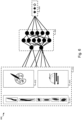
- Fig. 1 shows different processing methods 120 to obtain raw wood layers 130 from a wood log 110.
- the raw wood layers 130 may be raw veneer layers or raw wood slats, depending on the thickness of the layers and the used processing method 120 to obtain them.
- Raw veneer layers may be obtained by slicing a wood log 110 into thin layers with a thickness of at most 2 mm by means of a blade, e.g. a peeling knife or a slicing knife.
- Raw wood slats may be obtained by sawing a wood log 110 into slats with a thickness of at least 2 mm by means of a sawblade.
- a plurality of raw wood layers 130 can be obtained from a single log 110.
- the yield of raw wood layers 130 and their aesthetics, i.e. the grain and figure, is substantially determined by the used processing method 120.
- Fig. 1 further shows examples of commonly used processing methods 120 for raw veneer layers, i.e. slicing methods, such as rotary cutting 121, crown cutting 122, and quarter normal cutting 123.
- rotary cutting 121 the log is turned around its axis 124 against a blade that peels- or shaves off one continuous or semi-continuous raw veneer layer.
- Rotary cut raw veneer layers 127 may have a broad grain pattern which is typically less desirable for applications where aesthetics are important.
- crown cutting 122 the log is moved back and forth 125 against a blade across the growth rings of the wood log 110, thereby cutting through the heart of the log 110.
- Crown cut raw veneer layers 128 may have a flame grain pattern that is substantially similar to the grain pattern of plain sawn wood.
- the raw wood layer 130 is moved in front of a camera 221 that takes a digital image of the raw wood layer 130.
- the wording "in front of the camera” refers to the position wherein an optical lens or assembly of lenses of the camera 221 is able to capture an image of the raw wood layer's 130 surface.
- a bundle 131 of raw wood layers is moved in front of the camera 221 such that a digital image can be obtained of an outer raw wood layer of the bundle 131, i.e., the layer of the bundle 131 that is facing the camera 221.
- the camera 221 may for example be, amongst others, a rotating line camera, a line-scan camera, a 3D camera, an IP camera, a high-speed camera, a machine vision camera, a spectral camera, a contact image sensor, an area scan camera, a smart camera, or any other camera known to the person skilled in the art.
- the raw wood layer 130 or bundle 131 may be moved manually in front of the camera 221.
- the one or more layers are moved automatically or semi-automatically in front of the camera 221, e.g. by means of a conveyor belt 222.
- the determined grade and the surface area of the candidate cut section are then further used to determine the yield of the candidate cut section.
- the control unit 223 can determine the candidate cut section that obtains the highest yield from a raw wood layer 130, i.e. the optimal cut section.
- the optimal cut section is determined based on the detected quality-determining features of the raw wood layer 130. Considering both the surface area and the grade of a candidate cut section may improve the determining of the optimal cut section as the yield is determined more accurately.
- the graded raw wood layers 130 can be sorted and stacked into batches 225 of the same grade by means of a sorting system 224.
- the control unit 223 may transmit 227 the determined grade and optimal cut section of a raw wood layer 130 or bundle 131 to sorting system 224.
- the sorting system 224 may comprise a manually operated system, an automatically operated system, or a combination thereof.
- Such a sorting system may for example be, amongst others, a robotic arm, a veneer stacking machine, a pusher sorter, a cross belt sorter, or any other sorting system known to the person skilled in the art.
- the sorted batches 225 of graded raw wood layers 130 or bundles 131 may be transported to a storage space 230, where they can be stored until they are needed for manufacturing an end product such as decorative wood panels.
- One or more suitable batches 225 i.e. batches 225 of raw wood layers 130 or bundles 131 with a desired grade, may be selected and picked from the storage space 230 by a picking system to be further processed into decorative wood panels.
- the batches 255 may for example be picked according to the desired quality and dimensions of the decorative wood panels.
- the picked batches 225 are then transported to a cutting system for cutting 240 the raw wood layers 130 according to their determined optimal cut section.
- the sorted batches 225 of graded raw wood layers 130 or bundles 131 may be transported substantially directly to the cutting system, i.e. without being stored in a storage space 230.
- Cutting 240 the raw wood layers 130 according to their determined optimal cut section may further comprise a trimming step 241 and a clipping step 242.
- the trimming step 241 the raw wood layers 130 are trimmed according to the length of the optimal cut section by means of a trimming system.
- the raw wood layers 130 are clipped to the width of the optimal cut section by a clipping system, during the clipping step 242.
- Trimming 241 and clipping 242 may for example be performed by means of, amongst others, a blade, a knife, a sawblade, laser cutting, waterjet cutting, machine cutting, or any other cutting means known to the person skilled in the art.
- trimming 241 and clipping 242 may be performed in the reversed order, performed in a single step, or performed by a single apparatus or system.
- Trimming 241 and clipping 242 may be performed manually or semi-automatically by an operator.
- the operator may for example align the optimal cut section of the raw wood layers 130 with the cutting means of the trimming system or clipping system, such that the layers 130 are cut according to the determined optimal cut section.
- the optimal cut section may have been transmitted 228 from the control unit 223 to the cutting step 240 by for example marking the surface of the raw wood layers 130, e.g. by painting, drawing, printing, or engraving the optimal cut section on the raw wood layer's surface.
- an information carrier may be scanned or read out prior to trimming 241 or clipping 242.
- the optimal cut section may then for example be conveyed to the operator by projecting the optimal cut section on the raw wood layer's surface, e.g. by a light-source or a laser.
- trimming 241 and clipping 242 may further be performed automatically, i.e. without substantial interference of an operator.
- An operator may for example feed the raw wood layers 130 of a picked batch 225 into an automated cutting system 240, configured to automatically trim 241 and clip 242 the raw wood layers according to their optimal cut section.
- feeding the raw wood layers 130 of a picked batch 225 into the automated cutting system 240 may further be performed without substantial interference of an operator, e.g. by means of a robotic arm or a conveyor belt.
- Fig. 3 illustrates steps 300 performed for determining the optimal cut section with an optimal yield according to an example embodiment.
- steps 300 may be performed by control unit 223 to determine the optimal cut section of raw wood layers 130.
- a digital image of a raw wood layer is obtained in a first step 310, to detect the quality-determining features 324 of said raw wood layer by means of an image processing method in a second step 320.
- Such an image processing method may for example be, amongst others, pattern recognition, template matching, machine learning, or any other image processing method known to the person skilled in the art.
- Detecting quality-determining features 324 may include, amongst others, recognizing a feature, recognizing the type of a feature, determining the location of a feature on the raw wood layer, and determining the dimensions of a feature.
- the type of detected quality-determining feature 324 may preferably be a defect, a colour, or a cutting pattern.
- a quality-determining feature may thus have a negative or a positive effect on the grade of a candidate cut section.
- a defect is to be understood as an abnormality or irregularity in the raw wood layer, for example caused by injuries, insects, or fungi.
- a quality-determining feature 324 of the defect type may be a knot, a knot hole, a mineral line, a bird peck, a stain, a burl, a cutting error, a coarse grain, a raised grain, sapwood, fungal damage, an insect defect, a shake, a split, or a twisted fibre.
- a cutting pattern is to be understood as the grain and figure of a raw wood layer resulting from the used slicing method or sawing method to obtain the raw wood layer from a wooden log.
- a quality-determining feature 324 of the cutting pattern type may preferably be a rotary cut, a crown cut, a quarter normal cut, a quarter rift cut, or a combination thereof.
- a raw wood layer with a certain cutting pattern type may include variations in the grain and figure that contribute to the grade, which may further be detected as a quality-determining feature 324.
- a quality-determining feature of the colour type may preferably be a primary colour, a secondary colour, a colour distribution, a colour difference, or a colour variation.
- a colour difference may for example be the difference between the primary colour and the secondary colour.
- a colour variation may for example be the variation between the primary colour and a reference colour.
- the image processing step 320 may further be performed by a single algorithm configured to detect one or more of these feature types, i.e. defects, colours, and cutting patterns.
- the image processing step 320 may comprise one or more different algorithms specifically suited for defect detection 321, colour detection 322, and cutting pattern detection 323.
- the detected quality-determining features 324 are used to determine a candidate cut section on the raw wood layer surface, i.e. a section of certain shape and size that is to be cut from the raw wood layer later in the production process.
- determining a candidate cut section may include determining the shape and dimensions of the candidate cut section.
- the candidate cut section defines a cropping of the raw wood layer to a substantially rectangular shape.
- the term 'cropping' is to be understood as that the outside edges of the rectangularly shaped candidate cut section are substantially parallel to the respective outer edges of the raw wood layer from which the candidate cut section is to be cut.
- the rectangularly shaped cut section may be substantially parallel to the longitudinal direction of the raw wood layer.
- a minimum length of the candidate cut section may further be determined based on a length of the decorative wood panels, i.e. an end product to be produced from the raw wood layer.
- the length of the candidate cut section may be selected from a collection of lengths representative for all suitable lengths to produce decorative wood panels.
- the candidate cut section may further be characterized by a minimum width.
- the minimum width of the candidate cut section may for example, amongst others, relate to the width of the decorative wood panels, the desired aesthetics of the decorative wood panels, the machinery in the manufacturing process, or the storage capabilities. This can ensure that the processed wood layers meet product requirements and that a suitable search space is defined for the optimization problem, i.e. determining the optimal cut section.
- the detected quality-determining features 324 are adjusted to only include the features 341 comprised in the candidate cut section, i.e. the adjusted features 341. In other words, detected quality-determining features 324 that are not spatially located within the boundaries of the candidate cut section are not considered to determine the grade.
- the grade 351 of the candidate cut section which contributes to the yield, is then determined from these adjusted quality-determining features 341 during a grading step 350.
- the grade 351 is thus determined based on how the raw wood layer will be cut later in the manufacturing process, i.e. according to the candidate cut section. This cutting will contribute to the grade 351, and will thus also contribute to the yield of the final decorative wood panel, by the removal of undesired quality-determining features.
- the detected features 324 that are not spatially located within the boundaries of the candidate cut section would be permanently removed from the wood layer, thereby no longer contributing to the grade 351 of the processed wood layer.
- the surface area 344 of the candidate cut section is also taken into account to determine the yield 360 of the raw wood layer. In doing so, a candidate cut section with a substantial surface area 344 and a lower grade 351 can result in a higher yield relative to a candidate cut section with an insignificant surface area 344 and a higher grade 351.
- the yield may represent the value of the candidate cut section, i.e. the value potential of the raw wood layer after being cut according to the cut section.
- the yield may for example be expressed as a numerical score, a letter score, or a monetary value.
- the length, width, and/or location of the current candidate cut section may then iteratively be adjusted 371 to improve the grade 351 and/or the surface area 344 of the candidate cut section, and thus the yield of the raw wood layer. This may for example be achieved by excluding different or more undesired quality-determining features 324, by including desired quality-determining features, or by adjusting the surface area 344 of the candidate cut section.
- the optimal cut section 372 with a highest yield i.e. the optimal yield, can iteratively be determined.
- iteratively adjusting 371 the candidate cut section and determining the corresponding yield 360 allows determining the candidate cut section that results in the highest yield from a raw wood layer, i.e. the optimal cut section 372.
- the optimal cut section 372 is determined based on the detected quality-determining features 324 of the raw wood layer. This allows to identify a single portion or section that maximizes the yield from a raw wood layer for manufacturing decorative wood panels.
- Fig. 4 shows a raw wood layer 401 comprising a rectangularly shaped cut section 402 according to an embodiment.
- the raw wood layer 401 comprises a plurality of quality-determining features of the defect type, including two lengthwise cracks or separations of the wood, i.e. splits 411, 412, and four branches that were removed from the tree, i.e. knots 421, 422, 423, 424.
- Raw wood layer 401 further comprises a substantial flame grain pattern 430, characteristic for a quality-determining feature of the cutting pattern type, i.e. a crown cut.
- the rectangularly shaped cut section 402 is thus determined to obtain the highest yield from raw wood layer 401 by for example excluding undesired quality-determining features 411, 421, 422, 423 and including the most desirable section of the flame grain pattern, while also ensuring a substantial surface area.
- Fig. 5 shows a training process 500 of a first classifier 520 to detect quality-determining features 530 from the digital image 510 of a raw wood layer according to an embodiment.
- the training process 500 may start by gathering a plurality of digital images 501 of raw wood layers, i.e. training data.
- the digital images 501 of raw wood layers may be annotated with information on the quality-determining features 411, 412, 421, 422, 423, 424 that should be detected by the first classifier, e.g. by a graphical image annotation tool.
- a dataset of annotated images is constructed that comprises, amongst others, the location of the features, the type of features, the boundaries of the features, and the dimensions of the features.
- a trained classifier for colour detection may detect the colour of the raw wood layer's surface at distinct spatial points on the digital image.
- the colour is determined in a perceptually uniform colour space such as the CIELAB colour space or CIELUV colour space.
- a numerical change in colour value can correspond relatively better to a similar colour change as perceived by the human eye, compared to an additive or subtractive colour model such as RGB, RYB, CMY, or CMYK.
- it allows to use the CIEDE2000 formula to quantify the distance or difference between detected colour values, or between a detected colour value and a reference colour value, approximating how humans perceive colour differences.
- Fig. 6 shows a second classifier 620 trained to determine the grade 630 of a candidate cut section from the quality-determining features 610 included in the candidate cut section according to an embodiment.
- the quality-determining features 610 may for example be one or more of the defect type 611, the colour type 612, and the cutting pattern type 613.
- these quality-determining features 610 have been detected by the first classifier, i.e. the input of the second classifier may be the output of the first classifier.
- a production property that contributes to determining the grade 630 of the candidate cut section may for example be, amongst others, a raw wood layer width, a raw wood layer length, a raw wood layer thickness, a raw wood layer surface area, a log number, a sequence number, or a quantity of raw wood layers comprised in a bundle.
- the second classifier 620 may be trained by supervised learning, wherein the grade of raw wood layers, their respective quality-determining features 610, and their production properties are presented to the second classifier 620.
- a training dataset is constructed that relates the grade 630 of a raw wood layer to the quality-determining features 610 and the production properties of that layer.
- the second classifier 620 may be pre-trained on a benchmark dataset, trained by unsupervised learning, or trained by reinforcement learning.
- the trained classifier may, amongst others, be an artificial neural network, a decision tree, a support-vector machine, regression analysis, a Bayesian network, a genetic algorithm, or any other classifier known to the person skilled in the art.
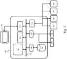
- Fig. 7 shows a suitable computing system 700 enabling to implement embodiments of the above described method according to the invention.
- Computing system 700 may in general be formed as a suitable general-purpose computer and comprise a bus 710, a processor 702, a local memory 704, one or more optional input interfaces 714, one or more optional output interfaces 716, a communication interface 712, a storage element interface 706, and one or more storage elements 708.
- Bus 710 may comprise one or more conductors that permit communication among the components of the computing system 700.
- Processor 702 may include any type of conventional processor or microprocessor that interprets and executes programming instructions.
- Communication interface 712 may comprise any transceiver-like mechanism such as for example one or more Ethernet interfaces that enables computing system 700 to communicate with other devices and/or systems such as for example, amongst others, a camera 221, a sorting system 224, a trimming system 241, or a clipping system 242.
- the communication interface 712 of computing system 700 may be connected to such another computing system by means of a local area network (LAN) or a wide area network (WAN) such as for example the internet.
- LAN local area network
- WAN wide area network
- Storage element interface 706 may comprise a storage interface such as for example a Serial Advanced Technology Attachment (SATA) interface or a Small Computer System Interface (SCSI) for connecting bus 710 to one or more storage elements 708, such as one or more local disks, for example SATA disk drives, and control the reading and writing of data to and/or from these storage elements 708.
- SATA Serial Advanced Technology Attachment
- SCSI Small Computer System Interface
- the storage element(s) 708 above is/are described as a local disk, in general any other suitable computer-readable media such as a removable magnetic disk, optical storage media such as a CD or DVD, - ROM disk, solid state drives, flash memory cards, etc. could be used.
Landscapes
- Engineering & Computer Science (AREA)
- Life Sciences & Earth Sciences (AREA)
- Business, Economics & Management (AREA)
- Physics & Mathematics (AREA)
- General Physics & Mathematics (AREA)
- Manufacturing & Machinery (AREA)
- Theoretical Computer Science (AREA)
- Human Resources & Organizations (AREA)
- Wood Science & Technology (AREA)
- Health & Medical Sciences (AREA)
- Forests & Forestry (AREA)
- Strategic Management (AREA)
- Economics (AREA)
- General Health & Medical Sciences (AREA)
- General Business, Economics & Management (AREA)
- Tourism & Hospitality (AREA)
- Computer Vision & Pattern Recognition (AREA)
- Chemical & Material Sciences (AREA)
- Marketing (AREA)
- Quality & Reliability (AREA)
- Game Theory and Decision Science (AREA)
- Operations Research (AREA)
- Entrepreneurship & Innovation (AREA)
- Food Science & Technology (AREA)
- Medicinal Chemistry (AREA)
- Analytical Chemistry (AREA)
- Biochemistry (AREA)
- Immunology (AREA)
- Pathology (AREA)
- Development Economics (AREA)
- Primary Health Care (AREA)
- Image Analysis (AREA)
Claims (13)
- Computerimplementiertes Verfahren (300) zum Verarbeiten einer rohen Holzschicht für die Herstellung von dekorativen Holzplatten, wobei das Verfahren die folgenden Schritte umfasst:- Erhalten (310) eines digitalen Bildes der rohen Holzschicht;- Erfassen (320) von Qualitätsbestimmungsmerkmalen (324) der rohen Holzschicht aus dem digitalen Bild;
wobei das computerimplementierte Verfahren gekennzeichnet ist durch- Bestimmen (330) eines Kandidatenschnittabschnittes auf der rohen Holzschicht, wobei der Kandidatenschnittabschnitt ein Zuschneiden der rohen Holzschicht zu einer rechteckigen Form (402) mit einer minimalen Länge definiert, die basierend auf einer Länge der dekorativen Holzplatten bestimmt wird;- Bestimmen (350) eines Grads des Kandidatenschnittabschnittes aus den Qualitätsbestimmungsmerkmalen, die in dem Schnittabschnitt enthalten sind;- Bestimmen (360) einer Ausbeute des Kandidatenschnittabschnittes basierend auf einer Fläche (344) des Kandidatenschnittabschnittes und dem Grad (351); und- Bestimmen (370) eines optimalen Schnittabschnittes als den Kandidatenschnittabschnitt, der in einer höchsten Ausbeute resultiert, durch, auf iterative Weise:- Einstellen einer Länge, einer Breite und/oder einer Stelle des Kandidatenschnittabschnittes (402) auf der rohen Holzschicht (401); und- Bestimmen der Ausbeute für den eingestellten Kandidatenschnittabschnitt (330, 350, 360). - Computerimplementiertes Verfahren nach Anspruch 1, wobei das Erfassen (320) der Qualitätsbestimmungsmerkmale durch einen ersten Klassifizierer (520) durchgeführt wird, der zum Erfassen der Qualitätsbestimmungsmerkmale (530) aus dem digitalen Bild (510) trainiert ist.
- Computerimplementiertes Verfahren nach einem der vorhergehenden Ansprüche, wobei die Qualitätsbestimmungsmerkmale (324) einen Merkmalstyp kennzeichnen, der aus der Gruppe ausgewählt ist, die zumindest eines von einem Defekt (321), einer Farbe (322) und einem Schnittmuster (323) umfasst.
- Computerimplementiertes Verfahren nach Anspruch 3, wobei ein Qualitätsbestimmungsmerkmal des Defekttyps (321) aus der Gruppe ausgewählt ist, die zumindest eines von einem Knoten, einem Knotenloch, einer Minerallinie, einem Vogelpick, einem Fleck, einer Noppe, einem Schneidfehler, einem groben Korn, einem erhabenen Korn, Splintholz, Pilzschäden, einem Insektendefekt, einem Schütteln, einem Spalt und einer verdrehten Faser umfasst.
- Computerimplementiertes Verfahren nach Anspruch 3, wobei ein Qualitätsbestimmungsmerkmal des Schnittmustertyps (323) aus der Gruppe ausgewählt ist, die zumindest eines von einem Rotationsschnitt, einem Kronenschnitt, einem Viertelnormalschnitt, einem Viertelrissschnitt oder einer Kombination davon umfasst.
- Computerimplementiertes Verfahren nach Anspruch 3, wobei ein Qualitätsbestimmungsmerkmal des Farbtyps (322) aus der Gruppe ausgewählt ist, die zumindest eines von einer Primärfarbe, einer Sekundärfarbe, einer Farbverteilung, einem Farbunterschied und einer Farbvariation umfasst.
- Computerimplementiertes Verfahren nach einem der vorhergehenden Ansprüche, wobei das Bestimmen (350) des Grads des Kandidatenschnittabschnittes durch einen zweiten Klassifizierer (620) durchgeführt wird, der zum Bestimmen des Grads (630) aus den Qualitätsbestimmungsmerkmalen (610), die in dem Kandidatenschnittabschnitt enthalten sind, trainiert ist.
- Computerimplementiertes Verfahren nach Anspruch 7, ferner umfassend Erhalten von zumindest einer Produktionseigenschaft der rohen Holzschicht und wobei der zweite Klassifizierer (620) ferner zum Bestimmen des Grads (630) aus einer oder mehreren Produktionseigenschaften trainiert ist.
- Verfahren (200) zum Verarbeiten einer rohen Holzschicht (130), umfassend:- Erhalten der rohen Holzschicht (130);- Aufnehmen eines digitalen Bildes der rohen Holzschicht mittels einer Kamera (221);- Bestimmen, durch eine Steuereinheit (223), eines optimalen Schnittabschnittes mit einer höchsten Ausbeute aus dem digitalen Bild durch Durchführen des computerimplementierten Verfahrens nach einem der Ansprüche 1 bis 8;- Sortieren (225) der rohen Holzschicht gemäß dem Grad des optimalen Schnittabschnittes;- Auswählen einer Charge von sortierten rohen Holzschichten gemäß dem Grad des optimalen Schnittabschnittes;- Beschneiden (241) der Länge der rohen Holzschicht gemäß der Länge des optimalen Schnittabschnittes; und- Stutzen (242) der Breite der rohen Holzschicht gemäß der Breite des optimalen Schnittabschnittes.
- System zum Verarbeiten einer rohen Holzschicht, wobei das System Folgendes umfasst:- eine Kamera (221), die konfiguriert ist, um ein digitales Bild der rohen Holzschicht (130) zu erhalten;- eine Steuereinheit (223), die konfiguriert ist, um einen optimalen Schnittabschnitt mit einer höchsten Ausbeute aus dem digitalen Bild durch Durchführen des computerimplementierten Verfahrens nach einem der Ansprüche 1 bis 8 zu bestimmen;- ein Sortiersystem (224), das konfiguriert ist, um die rohe Holzschicht gemäß dem Grad des optimalen Schnittabschnittes zu sortieren (225);- ein Auswahlsystem, das konfiguriert ist, um eine Charge von sortierten rohen Holzschichten gemäß dem Grad des optimalen Schnittabschnittes auszuwählen;- ein Beschneidungssystem (241), das konfiguriert ist, um die Länge der rohen Holzschicht gemäß der Länge des optimalen Schnittabschnittes zu beschneiden; und- ein Stutzsystem (242), das konfiguriert ist, um die Breite der rohen Holzschicht gemäß der Breite des optimalen Schnittabschnittes zu stutzen.
- Datenverarbeitungssystem, das konfiguriert ist, um das computerimplementierte Verfahren (300) nach einem der Ansprüche 1 bis 8 durchzuführen.
- Computerprogramm, umfassend Anweisungen, die, wenn das Programm durch einen Computer ausgeführt wird, bewirken, dass der Computer das computerimplementierte Verfahren (300) nach einem der Ansprüche 1 bis 8 durchführt.
- Computerlesbares Medium, das Anweisungen umfasst, die, wenn sie durch einen Computer ausgeführt werden, bewirken, dass der Computer das computerimplementierte Verfahren (300) nach einem der Ansprüche 1 bis 8 durchführt.
Priority Applications (1)
| Application Number | Priority Date | Filing Date | Title |
|---|---|---|---|
| HRP20250702TT HRP20250702T1 (hr) | 2021-08-20 | 2022-08-12 | Metoda i sustav za obradu sirovih drvenih slojeva |
Applications Claiming Priority (1)
| Application Number | Priority Date | Filing Date | Title |
|---|---|---|---|
| BE20215666A BE1029695B1 (nl) | 2021-08-20 | 2021-08-20 | Een werkwijze en een systeem voor de verwerking van onbewerkte houtlagen |
Publications (3)
| Publication Number | Publication Date |
|---|---|
| EP4137283A1 EP4137283A1 (de) | 2023-02-22 |
| EP4137283C0 EP4137283C0 (de) | 2025-04-30 |
| EP4137283B1 true EP4137283B1 (de) | 2025-04-30 |
Family
ID=78401956
Family Applications (1)
| Application Number | Title | Priority Date | Filing Date |
|---|---|---|---|
| EP22190218.2A Active EP4137283B1 (de) | 2021-08-20 | 2022-08-12 | Verfahren und system zur verarbeitung von rohen holzschichten |
Country Status (3)
| Country | Link |
|---|---|
| EP (1) | EP4137283B1 (de) |
| BE (1) | BE1029695B1 (de) |
| HR (1) | HRP20250702T1 (de) |
Families Citing this family (2)
| Publication number | Priority date | Publication date | Assignee | Title |
|---|---|---|---|---|
| US12480933B2 (en) * | 2024-04-10 | 2025-11-25 | BotBuilt, Inc. | Systems and methods for automatically characterizing lumber |
| CN119682008B (zh) * | 2024-11-08 | 2025-12-26 | 国际竹藤中心 | 一种竹材的加工方法和装置 |
Family Cites Families (2)
| Publication number | Priority date | Publication date | Assignee | Title |
|---|---|---|---|---|
| US8113098B1 (en) * | 2008-11-28 | 2012-02-14 | Longfellow James L | Automated shingle milling system |
| SK288751B6 (sk) * | 2015-08-25 | 2020-05-04 | Biatec Group A S | Spôsob optimalizácie rezania plošných výrobkov z prírodného materiálu, najmä z dreva, a systém na jeho vykonávanie |
-
2021
- 2021-08-20 BE BE20215666A patent/BE1029695B1/nl active IP Right Grant
-
2022
- 2022-08-12 EP EP22190218.2A patent/EP4137283B1/de active Active
- 2022-08-12 HR HRP20250702TT patent/HRP20250702T1/hr unknown
Also Published As
| Publication number | Publication date |
|---|---|
| HRP20250702T1 (hr) | 2025-10-24 |
| EP4137283C0 (de) | 2025-04-30 |
| EP4137283A1 (de) | 2023-02-22 |
| BE1029695A1 (nl) | 2023-03-14 |
| BE1029695B1 (nl) | 2023-03-20 |
Similar Documents
| Publication | Publication Date | Title |
|---|---|---|
| EP4137283B1 (de) | Verfahren und system zur verarbeitung von rohen holzschichten | |
| JP5373989B1 (ja) | 単板の選別堆積装置及び単板選別方法 | |
| JP2006322774A (ja) | 木材の節探査方法及び装置及びプログラム | |
| US8091390B2 (en) | Hide folding system and method | |
| JP2014215233A (ja) | 単板の選別堆積装置及び単板選別方法 | |
| US20210398270A1 (en) | Method and system for layered wood product production | |
| US20050147286A1 (en) | Identifying defects in decorative wood panels | |
| EP4052875B1 (de) | Furniersortiersteuervorrichtung, verfahren zur furnierssortierungssteuerung und furniersortiersteuerprogramm | |
| CA3245837A1 (en) | Post-sawing quality control, inspection and packaging of shingles in computer-assisted wood shingle manufacturing | |
| US12163947B2 (en) | Method and system for characterizing undebarked wooden logs and computing optimal debarking parameters in real time | |
| Wells et al. | Defect detection performance of automated hardwood lumber grading system | |
| CN108362703A (zh) | 一种基于人工智能的单板检测方法和检测设备 | |
| EP2528716B1 (de) | Verfahren zur identifikation eines einzelnen baumstamms | |
| US8113098B1 (en) | Automated shingle milling system | |
| Sobey et al. | Detection and sizing visual features in wood using tonal measures and a classification algorithm | |
| US20240025074A1 (en) | Computer-Assisted Shingle Sawing Method and Installation | |
| CN119396095A (zh) | 一种智能化瓦楞纸箱生产方法及控制系统 | |
| US20250196392A1 (en) | Post-Sawing Quality Control, Inspection and Packaging of Shingles in Computer-Assisted Wood Shingle Manufacturing | |
| Sukrisdyanto et al. | Wood Strength Classification Based on RGB Color and Image Texture Using KNN Method | |
| CA3136766C (en) | Computer-assisted shingle sawing method and installation | |
| Kline et al. | Scanning hardwood lumber for processing and grading-what to do now and why | |
| CN119217474A (zh) | 一种基于机器视觉的木料分割方法 | |
| Praschl et al. | Segmentation and Multi-facet Classification of Individual Logs | |
| CN120655608A (zh) | 一种再造烟叶抄造工段的缺陷监测方法 | |
| Buehlmann et al. | Detection capabilities of automated hardwood lumber defect-detection systems. |
Legal Events
| Date | Code | Title | Description |
|---|---|---|---|
| REG | Reference to a national code |
Ref country code: HR Ref legal event code: TUEP Ref document number: P20250702T Country of ref document: HR |
|
| PUAI | Public reference made under article 153(3) epc to a published international application that has entered the european phase |
Free format text: ORIGINAL CODE: 0009012 |
|
| STAA | Information on the status of an ep patent application or granted ep patent |
Free format text: STATUS: THE APPLICATION HAS BEEN PUBLISHED |
|
| AK | Designated contracting states |
Kind code of ref document: A1 Designated state(s): AL AT BE BG CH CY CZ DE DK EE ES FI FR GB GR HR HU IE IS IT LI LT LU LV MC MK MT NL NO PL PT RO RS SE SI SK SM TR |
|
| P01 | Opt-out of the competence of the unified patent court (upc) registered |
Effective date: 20230505 |
|
| STAA | Information on the status of an ep patent application or granted ep patent |
Free format text: STATUS: REQUEST FOR EXAMINATION WAS MADE |
|
| 17P | Request for examination filed |
Effective date: 20230822 |
|
| RBV | Designated contracting states (corrected) |
Designated state(s): AL AT BE BG CH CY CZ DE DK EE ES FI FR GB GR HR HU IE IS IT LI LT LU LV MC MK MT NL NO PL PT RO RS SE SI SK SM TR |
|
| STAA | Information on the status of an ep patent application or granted ep patent |
Free format text: STATUS: EXAMINATION IS IN PROGRESS |
|
| 17Q | First examination report despatched |
Effective date: 20231219 |
|
| RIC1 | Information provided on ipc code assigned before grant |
Ipc: G01N 33/46 20060101ALI20240704BHEP Ipc: B27L 5/00 20060101ALI20240704BHEP Ipc: B27L 5/06 20060101ALI20240704BHEP Ipc: B27M 1/08 20060101ALI20240704BHEP Ipc: G06Q 50/04 20120101ALI20240704BHEP Ipc: G06T 7/73 20170101ALI20240704BHEP Ipc: G06T 7/00 20170101ALI20240704BHEP Ipc: G06Q 10/04 20230101ALI20240704BHEP Ipc: B27G 1/00 20060101AFI20240704BHEP |
|
| GRAP | Despatch of communication of intention to grant a patent |
Free format text: ORIGINAL CODE: EPIDOSNIGR1 |
|
| STAA | Information on the status of an ep patent application or granted ep patent |
Free format text: STATUS: GRANT OF PATENT IS INTENDED |
|
| INTG | Intention to grant announced |
Effective date: 20240905 |
|
| GRAJ | Information related to disapproval of communication of intention to grant by the applicant or resumption of examination proceedings by the epo deleted |
Free format text: ORIGINAL CODE: EPIDOSDIGR1 |
|
| STAA | Information on the status of an ep patent application or granted ep patent |
Free format text: STATUS: EXAMINATION IS IN PROGRESS |
|
| INTC | Intention to grant announced (deleted) | ||
| GRAP | Despatch of communication of intention to grant a patent |
Free format text: ORIGINAL CODE: EPIDOSNIGR1 |
|
| STAA | Information on the status of an ep patent application or granted ep patent |
Free format text: STATUS: GRANT OF PATENT IS INTENDED |
|
| INTG | Intention to grant announced |
Effective date: 20241216 |
|
| GRAS | Grant fee paid |
Free format text: ORIGINAL CODE: EPIDOSNIGR3 |
|
| GRAA | (expected) grant |
Free format text: ORIGINAL CODE: 0009210 |
|
| STAA | Information on the status of an ep patent application or granted ep patent |
Free format text: STATUS: THE PATENT HAS BEEN GRANTED |
|
| AK | Designated contracting states |
Kind code of ref document: B1 Designated state(s): AL AT BE BG CH CY CZ DE DK EE ES FI FR GB GR HR HU IE IS IT LI LT LU LV MC MK MT NL NO PL PT RO RS SE SI SK SM TR |
|
| REG | Reference to a national code |
Ref country code: CH Ref legal event code: EP Ref country code: GB Ref legal event code: FG4D |
|
| REG | Reference to a national code |
Ref country code: DE Ref legal event code: R096 Ref document number: 602022013812 Country of ref document: DE |
|
| REG | Reference to a national code |
Ref country code: IE Ref legal event code: FG4D |
|
| P04 | Withdrawal of opt-out of the competence of the unified patent court (upc) registered |
Free format text: CASE NUMBER: APP_22720/2025 Effective date: 20250514 |
|
| U01 | Request for unitary effect filed |
Effective date: 20250509 |
|
| U07 | Unitary effect registered |
Designated state(s): AT BE BG DE DK EE FI FR IT LT LU LV MT NL PT RO SE SI Effective date: 20250516 |
|
| REG | Reference to a national code |
Ref country code: HR Ref legal event code: ODRP Ref document number: P20250702T Country of ref document: HR Payment date: 20250801 Year of fee payment: 4 |
|
| U20 | Renewal fee for the european patent with unitary effect paid |
Year of fee payment: 4 Effective date: 20250901 |
|
| PG25 | Lapsed in a contracting state [announced via postgrant information from national office to epo] |
Ref country code: ES Free format text: LAPSE BECAUSE OF FAILURE TO SUBMIT A TRANSLATION OF THE DESCRIPTION OR TO PAY THE FEE WITHIN THE PRESCRIBED TIME-LIMIT Effective date: 20250430 |
|
| PG25 | Lapsed in a contracting state [announced via postgrant information from national office to epo] |
Ref country code: NO Free format text: LAPSE BECAUSE OF FAILURE TO SUBMIT A TRANSLATION OF THE DESCRIPTION OR TO PAY THE FEE WITHIN THE PRESCRIBED TIME-LIMIT Effective date: 20250730 Ref country code: GR Free format text: LAPSE BECAUSE OF FAILURE TO SUBMIT A TRANSLATION OF THE DESCRIPTION OR TO PAY THE FEE WITHIN THE PRESCRIBED TIME-LIMIT Effective date: 20250731 |
|
| PG25 | Lapsed in a contracting state [announced via postgrant information from national office to epo] |
Ref country code: PL Free format text: LAPSE BECAUSE OF FAILURE TO SUBMIT A TRANSLATION OF THE DESCRIPTION OR TO PAY THE FEE WITHIN THE PRESCRIBED TIME-LIMIT Effective date: 20250430 |
|
| PGFP | Annual fee paid to national office [announced via postgrant information from national office to epo] |
Ref country code: HR Payment date: 20250801 Year of fee payment: 4 |
|
| PG25 | Lapsed in a contracting state [announced via postgrant information from national office to epo] |
Ref country code: RS Free format text: LAPSE BECAUSE OF FAILURE TO SUBMIT A TRANSLATION OF THE DESCRIPTION OR TO PAY THE FEE WITHIN THE PRESCRIBED TIME-LIMIT Effective date: 20250731 |
|
| REG | Reference to a national code |
Ref country code: HR Ref legal event code: T1PR Ref document number: P20250702 Country of ref document: HR |
|
| PG25 | Lapsed in a contracting state [announced via postgrant information from national office to epo] |
Ref country code: IS Free format text: LAPSE BECAUSE OF FAILURE TO SUBMIT A TRANSLATION OF THE DESCRIPTION OR TO PAY THE FEE WITHIN THE PRESCRIBED TIME-LIMIT Effective date: 20250830 |
|
| PG25 | Lapsed in a contracting state [announced via postgrant information from national office to epo] |
Ref country code: SM Free format text: LAPSE BECAUSE OF FAILURE TO SUBMIT A TRANSLATION OF THE DESCRIPTION OR TO PAY THE FEE WITHIN THE PRESCRIBED TIME-LIMIT Effective date: 20250430 |
|
| PG25 | Lapsed in a contracting state [announced via postgrant information from national office to epo] |
Ref country code: CZ Free format text: LAPSE BECAUSE OF FAILURE TO SUBMIT A TRANSLATION OF THE DESCRIPTION OR TO PAY THE FEE WITHIN THE PRESCRIBED TIME-LIMIT Effective date: 20250430 |
|
| PG25 | Lapsed in a contracting state [announced via postgrant information from national office to epo] |
Ref country code: SK Free format text: LAPSE BECAUSE OF FAILURE TO SUBMIT A TRANSLATION OF THE DESCRIPTION OR TO PAY THE FEE WITHIN THE PRESCRIBED TIME-LIMIT Effective date: 20250430 |
|
| PLBE | No opposition filed within time limit |
Free format text: ORIGINAL CODE: 0009261 |
|
| STAA | Information on the status of an ep patent application or granted ep patent |
Free format text: STATUS: NO OPPOSITION FILED WITHIN TIME LIMIT |
|
| REG | Reference to a national code |
Ref country code: CH Ref legal event code: L10 Free format text: ST27 STATUS EVENT CODE: U-0-0-L10-L00 (AS PROVIDED BY THE NATIONAL OFFICE) Effective date: 20260311 |
|
| REG | Reference to a national code |
Ref country code: CH Ref legal event code: H13 Free format text: ST27 STATUS EVENT CODE: U-0-0-H10-H13 (AS PROVIDED BY THE NATIONAL OFFICE) Effective date: 20260324 |
|
| PG25 | Lapsed in a contracting state [announced via postgrant information from national office to epo] |
Ref country code: MC Free format text: LAPSE BECAUSE OF FAILURE TO SUBMIT A TRANSLATION OF THE DESCRIPTION OR TO PAY THE FEE WITHIN THE PRESCRIBED TIME-LIMIT Effective date: 20250430 |
|
| 26N | No opposition filed |
Effective date: 20260202 |