EP4137271A1 - Method and system for drilling ceramic material - Google Patents
Method and system for drilling ceramic material Download PDFInfo
- Publication number
- EP4137271A1 EP4137271A1 EP22188828.2A EP22188828A EP4137271A1 EP 4137271 A1 EP4137271 A1 EP 4137271A1 EP 22188828 A EP22188828 A EP 22188828A EP 4137271 A1 EP4137271 A1 EP 4137271A1
- Authority
- EP
- European Patent Office
- Prior art keywords
- component
- liquid stream
- target region
- jet head
- series
- Prior art date
- Legal status (The legal status is an assumption and is not a legal conclusion. Google has not performed a legal analysis and makes no representation as to the accuracy of the status listed.)
- Pending
Links
- 238000005553 drilling Methods 0.000 title claims abstract description 48
- 238000000034 method Methods 0.000 title claims abstract description 17
- 229910010293 ceramic material Inorganic materials 0.000 title 1
- 239000007788 liquid Substances 0.000 claims abstract description 89
- 239000002245 particle Substances 0.000 claims abstract description 21
- 239000000463 material Substances 0.000 claims abstract description 19
- 238000003754 machining Methods 0.000 claims abstract description 7
- 239000011153 ceramic matrix composite Substances 0.000 description 8
- 238000001816 cooling Methods 0.000 description 6
- 239000000446 fuel Substances 0.000 description 5
- 239000000919 ceramic Substances 0.000 description 4
- 229920002134 Carboxymethyl cellulose Polymers 0.000 description 3
- 235000010948 carboxy methyl cellulose Nutrition 0.000 description 3
- 229920006184 cellulose methylcellulose Polymers 0.000 description 3
- 238000012710 chemistry, manufacturing and control Methods 0.000 description 3
- 230000009467 reduction Effects 0.000 description 3
- 230000008901 benefit Effects 0.000 description 2
- 238000009792 diffusion process Methods 0.000 description 2
- 230000003068 static effect Effects 0.000 description 2
- XLYOFNOQVPJJNP-UHFFFAOYSA-N water Substances O XLYOFNOQVPJJNP-UHFFFAOYSA-N 0.000 description 2
- 229910052580 B4C Inorganic materials 0.000 description 1
- 239000000853 adhesive Substances 0.000 description 1
- 230000001070 adhesive effect Effects 0.000 description 1
- 238000013459 approach Methods 0.000 description 1
- INAHAJYZKVIDIZ-UHFFFAOYSA-N boron carbide Chemical compound B12B3B4C32B41 INAHAJYZKVIDIZ-UHFFFAOYSA-N 0.000 description 1
- 230000008859 change Effects 0.000 description 1
- 238000002485 combustion reaction Methods 0.000 description 1
- 238000004891 communication Methods 0.000 description 1
- 230000006835 compression Effects 0.000 description 1
- 238000007906 compression Methods 0.000 description 1
- 238000010276 construction Methods 0.000 description 1
- 238000012937 correction Methods 0.000 description 1
- 229910003460 diamond Inorganic materials 0.000 description 1
- 239000010432 diamond Substances 0.000 description 1
- 230000007246 mechanism Effects 0.000 description 1
- 238000012986 modification Methods 0.000 description 1
- 230000004048 modification Effects 0.000 description 1
- 239000003921 oil Substances 0.000 description 1
- 230000004044 response Effects 0.000 description 1
- 229910010271 silicon carbide Inorganic materials 0.000 description 1
- HBMJWWWQQXIZIP-UHFFFAOYSA-N silicon carbide Chemical compound [Si+]#[C-] HBMJWWWQQXIZIP-UHFFFAOYSA-N 0.000 description 1
- 239000002002 slurry Substances 0.000 description 1
- 229910000601 superalloy Inorganic materials 0.000 description 1
- 239000012720 thermal barrier coating Substances 0.000 description 1
Images



Classifications
-
- B—PERFORMING OPERATIONS; TRANSPORTING
- B24—GRINDING; POLISHING
- B24C—ABRASIVE OR RELATED BLASTING WITH PARTICULATE MATERIAL
- B24C3/00—Abrasive blasting machines or devices; Plants
- B24C3/32—Abrasive blasting machines or devices; Plants designed for abrasive blasting of particular work, e.g. the internal surfaces of cylinder blocks
- B24C3/325—Abrasive blasting machines or devices; Plants designed for abrasive blasting of particular work, e.g. the internal surfaces of cylinder blocks for internal surfaces, e.g. of tubes
- B24C3/327—Abrasive blasting machines or devices; Plants designed for abrasive blasting of particular work, e.g. the internal surfaces of cylinder blocks for internal surfaces, e.g. of tubes by an axially-moving flow of abrasive particles without passing a blast gun, impeller or the like along the internal surface
-
- B—PERFORMING OPERATIONS; TRANSPORTING
- B24—GRINDING; POLISHING
- B24C—ABRASIVE OR RELATED BLASTING WITH PARTICULATE MATERIAL
- B24C1/00—Methods for use of abrasive blasting for producing particular effects; Use of auxiliary equipment in connection with such methods
- B24C1/04—Methods for use of abrasive blasting for producing particular effects; Use of auxiliary equipment in connection with such methods for treating only selected parts of a surface, e.g. for carving stone or glass
- B24C1/045—Methods for use of abrasive blasting for producing particular effects; Use of auxiliary equipment in connection with such methods for treating only selected parts of a surface, e.g. for carving stone or glass for cutting
-
- B—PERFORMING OPERATIONS; TRANSPORTING
- B23—MACHINE TOOLS; METAL-WORKING NOT OTHERWISE PROVIDED FOR
- B23K—SOLDERING OR UNSOLDERING; WELDING; CLADDING OR PLATING BY SOLDERING OR WELDING; CUTTING BY APPLYING HEAT LOCALLY, e.g. FLAME CUTTING; WORKING BY LASER BEAM
- B23K26/00—Working by laser beam, e.g. welding, cutting or boring
- B23K26/08—Devices involving relative movement between laser beam and workpiece
- B23K26/0823—Devices involving rotation of the workpiece
-
- B—PERFORMING OPERATIONS; TRANSPORTING
- B23—MACHINE TOOLS; METAL-WORKING NOT OTHERWISE PROVIDED FOR
- B23K—SOLDERING OR UNSOLDERING; WELDING; CLADDING OR PLATING BY SOLDERING OR WELDING; CUTTING BY APPLYING HEAT LOCALLY, e.g. FLAME CUTTING; WORKING BY LASER BEAM
- B23K26/00—Working by laser beam, e.g. welding, cutting or boring
- B23K26/08—Devices involving relative movement between laser beam and workpiece
- B23K26/0869—Devices involving movement of the laser head in at least one axial direction
-
- B—PERFORMING OPERATIONS; TRANSPORTING
- B23—MACHINE TOOLS; METAL-WORKING NOT OTHERWISE PROVIDED FOR
- B23K—SOLDERING OR UNSOLDERING; WELDING; CLADDING OR PLATING BY SOLDERING OR WELDING; CUTTING BY APPLYING HEAT LOCALLY, e.g. FLAME CUTTING; WORKING BY LASER BEAM
- B23K26/00—Working by laser beam, e.g. welding, cutting or boring
- B23K26/14—Working by laser beam, e.g. welding, cutting or boring using a fluid stream, e.g. a jet of gas, in conjunction with the laser beam; Nozzles therefor
- B23K26/146—Working by laser beam, e.g. welding, cutting or boring using a fluid stream, e.g. a jet of gas, in conjunction with the laser beam; Nozzles therefor the fluid stream containing a liquid
-
- B—PERFORMING OPERATIONS; TRANSPORTING
- B23—MACHINE TOOLS; METAL-WORKING NOT OTHERWISE PROVIDED FOR
- B23K—SOLDERING OR UNSOLDERING; WELDING; CLADDING OR PLATING BY SOLDERING OR WELDING; CUTTING BY APPLYING HEAT LOCALLY, e.g. FLAME CUTTING; WORKING BY LASER BEAM
- B23K26/00—Working by laser beam, e.g. welding, cutting or boring
- B23K26/36—Removing material
- B23K26/38—Removing material by boring or cutting
- B23K26/382—Removing material by boring or cutting by boring
- B23K26/389—Removing material by boring or cutting by boring of fluid openings, e.g. nozzles, jets
-
- B—PERFORMING OPERATIONS; TRANSPORTING
- B23—MACHINE TOOLS; METAL-WORKING NOT OTHERWISE PROVIDED FOR
- B23K—SOLDERING OR UNSOLDERING; WELDING; CLADDING OR PLATING BY SOLDERING OR WELDING; CUTTING BY APPLYING HEAT LOCALLY, e.g. FLAME CUTTING; WORKING BY LASER BEAM
- B23K26/00—Working by laser beam, e.g. welding, cutting or boring
- B23K26/36—Removing material
- B23K26/40—Removing material taking account of the properties of the material involved
-
- B—PERFORMING OPERATIONS; TRANSPORTING
- B23—MACHINE TOOLS; METAL-WORKING NOT OTHERWISE PROVIDED FOR
- B23K—SOLDERING OR UNSOLDERING; WELDING; CLADDING OR PLATING BY SOLDERING OR WELDING; CUTTING BY APPLYING HEAT LOCALLY, e.g. FLAME CUTTING; WORKING BY LASER BEAM
- B23K37/00—Auxiliary devices or processes, not specially adapted for a procedure covered by only one of the other main groups of this subclass
- B23K37/02—Carriages for supporting the welding or cutting element
- B23K37/0211—Carriages for supporting the welding or cutting element travelling on a guide member, e.g. rail, track
- B23K37/0229—Carriages for supporting the welding or cutting element travelling on a guide member, e.g. rail, track the guide member being situated alongside the workpiece
-
- B—PERFORMING OPERATIONS; TRANSPORTING
- B23—MACHINE TOOLS; METAL-WORKING NOT OTHERWISE PROVIDED FOR
- B23K—SOLDERING OR UNSOLDERING; WELDING; CLADDING OR PLATING BY SOLDERING OR WELDING; CUTTING BY APPLYING HEAT LOCALLY, e.g. FLAME CUTTING; WORKING BY LASER BEAM
- B23K37/00—Auxiliary devices or processes, not specially adapted for a procedure covered by only one of the other main groups of this subclass
- B23K37/04—Auxiliary devices or processes, not specially adapted for a procedure covered by only one of the other main groups of this subclass for holding or positioning work
- B23K37/0426—Fixtures for other work
- B23K37/0452—Orientable fixtures
-
- B—PERFORMING OPERATIONS; TRANSPORTING
- B24—GRINDING; POLISHING
- B24C—ABRASIVE OR RELATED BLASTING WITH PARTICULATE MATERIAL
- B24C1/00—Methods for use of abrasive blasting for producing particular effects; Use of auxiliary equipment in connection with such methods
- B24C1/04—Methods for use of abrasive blasting for producing particular effects; Use of auxiliary equipment in connection with such methods for treating only selected parts of a surface, e.g. for carving stone or glass
-
- B—PERFORMING OPERATIONS; TRANSPORTING
- B24—GRINDING; POLISHING
- B24C—ABRASIVE OR RELATED BLASTING WITH PARTICULATE MATERIAL
- B24C7/00—Equipment for feeding abrasive material; Controlling the flowability, constitution, or other physical characteristics of abrasive blasts
- B24C7/0007—Equipment for feeding abrasive material; Controlling the flowability, constitution, or other physical characteristics of abrasive blasts the abrasive material being fed in a liquid carrier
-
- B—PERFORMING OPERATIONS; TRANSPORTING
- B26—HAND CUTTING TOOLS; CUTTING; SEVERING
- B26F—PERFORATING; PUNCHING; CUTTING-OUT; STAMPING-OUT; SEVERING BY MEANS OTHER THAN CUTTING
- B26F1/00—Perforating; Punching; Cutting-out; Stamping-out; Apparatus therefor
- B26F1/26—Perforating by non-mechanical means, e.g. by fluid jet
-
- B—PERFORMING OPERATIONS; TRANSPORTING
- B23—MACHINE TOOLS; METAL-WORKING NOT OTHERWISE PROVIDED FOR
- B23K—SOLDERING OR UNSOLDERING; WELDING; CLADDING OR PLATING BY SOLDERING OR WELDING; CUTTING BY APPLYING HEAT LOCALLY, e.g. FLAME CUTTING; WORKING BY LASER BEAM
- B23K2101/00—Articles made by soldering, welding or cutting
- B23K2101/001—Turbines
-
- B—PERFORMING OPERATIONS; TRANSPORTING
- B23—MACHINE TOOLS; METAL-WORKING NOT OTHERWISE PROVIDED FOR
- B23K—SOLDERING OR UNSOLDERING; WELDING; CLADDING OR PLATING BY SOLDERING OR WELDING; CUTTING BY APPLYING HEAT LOCALLY, e.g. FLAME CUTTING; WORKING BY LASER BEAM
- B23K2103/00—Materials to be soldered, welded or cut
- B23K2103/18—Dissimilar materials
- B23K2103/26—Alloys of Nickel and Cobalt and Chromium
Definitions
- a gas turbine engine typically includes a fan section, a compressor section, a combustor section and a turbine section. Air entering the compressor section is compressed and delivered into the combustion section where it is mixed with fuel and ignited to generate a high-pressure and temperature exhaust gas flow. The high-pressure and temperature exhaust gas flow expands through the turbine section to drive the compressor and the fan section.
- the compressor section may include low and high pressure compressors, and the turbine section may also include low and high pressure turbines.
- Airfoils in the turbine section are typically formed of a superalloy and may include thermal barrier coatings to extend temperature capability and lifetime. Ceramic matrix composite (“CMC”) materials are also being considered for airfoils. Among other attractive properties, CMCs have high temperature resistance. It has been a challenge, however, to develop an efficient way to machine features, such as cooling holes, into CMCs.
- One methodology is to drill deep, small-diameter holes in the CMCs.
- grinding, laser, ultrasonic and abrasive waterjet machining can have issues of poor surface integrity, high tool wear, and low productivity.
- a method of machining a hole in a component that includes mounting a component in a drilling machine.
- the component has a target region at which a hole is to be drilled, and the component and a jet head are situated relative to each other in a drilling arrangement in which the target region is at a first position that is vertically equal to or vertically above a second position at which the jet head is located.
- a liquid stream is jetted from the jet head.
- the liquid stream contains either abrasive particles or a laser beam.
- the liquid stream impinges the target region and the abrasive particles or the laser beam cause removal of material from the component at the target region to form the hole in the component.
- the liquid stream rebounds off of the component as back-splash liquid, and the drilling arrangement causes gravitational draining of the back-splash liquid from the target region to reduce interference between the back-splash liquid and the liquid stream.
- An embodiment of the above includes, relative to the component, moving the jet head such that the liquid stream scans across the target region.
- a further embodiment of any of the above includes, relative to the component, moving the jet head such that the liquid stream scans the target region in a spiral pattern.
- a further embodiment of any of the above includes providing a computerized 3-dimensional model of the hole that is to be drilled, dividing the model into a series of successive 2-dimensional layers, and relative to the component moving the jet head such that the liquid stream scans the target region layer-by-layer of the series of successive 2-dimensional layers such that the abrasive particles or the laser beam causes removal of the material layer-by-layer.
- initial layers of the series of successive 2-dimensional layers successively decrease in area such that the hole includes a tapered section.
- subsequent layers of the series of successive 2-dimensional layers are successively equal in area such that the hole includes a uniform section.
- a further embodiment of any of the above includes, relative to the component, moving the jet head such that the liquid stream scans the target region in a series of spiral patterns layer-by-layer of the series of successive 2-dimensional layers.
- liquid stream is continuous through the series of spiral patterns.
- the spiral patterns alternate between inside-out movement of the jet head and outside-in movement of the jet head.
- the first position is vertically above the second position.
- a system for machining a hole in a component that includes a drilling machine that has a holder and a jet head.
- the holder is operable to mount a component that has a target region at which a hole is to be drilled.
- the holder and the jet head are situated or capable of being situated relative to each other in a drilling arrangement in which the target region is at a first position that is vertically equal to or vertically above a second position at which the jet head is located.
- the drilling machine is operable to jet a liquid stream from the jet head.
- the liquid stream contains either abrasive particles or a laser beam the liquid stream to impinge the target region such that the abrasive particles or the laser beam causes removal of material from the component at the target region to form the hole in the component.
- the liquid stream rebounds off of the component as back-splash liquid, and the drilling arrangement causes gravitational draining of the back-splash liquid from the target region to reduce interference between the back-splash liquid and the liquid stream.
- the drilling machine includes an electronic controller that is configured, relative to the component, to move the jet head such that the liquid stream scans across the target region.
- the controller is configured to move the jet head such that the liquid stream scans the target region in a spiral pattern.
- the controller includes a computerized 3-dimensional model of the hole that is to be drilled, the model is divided into a series of successive 2-dimensional layers, and the controller is configured to move the jet head such that the liquid stream scans the target region layer-by-layer of the series of successive 2-dimensional layers such that the abrasive particles or the laser beam causes removal of the material layer-by-layer.
- initial layers of the series of successive 2-dimensional layers successively decrease in area such that the hole includes a tapered section.
- subsequent layers of the series of successive 2-dimensional layers are successively equal in area such that the hole includes a uniform section.
- the controller is configured to move the j et head such that the liquid stream scans the target region in a series of spiral patterns layer-by-layer of the series of successive 2-dimensional layers.
- controller is operable to continuously maintain the liquid stream throughout the series of spiral patterns.
- the controller is configured to alternate the spiral patterns between inside-out movement of the jet head and outside-in movement of the jet head.
- the first position is vertically above the second position.
- the present disclosure may include any one or more of the individual features disclosed above and/or below alone or in any combination thereof.
- FIG. 1 schematically illustrates a gas turbine engine 20.
- the gas turbine engine 20 is disclosed herein as a two-spool turbofan that generally incorporates a fan section 22, a compressor section 24, a combustor section 26 and a turbine section 28.
- the fan section 22 drives air along a bypass flow path B in a bypass duct defined within a housing 15 such as a fan case or nacelle, and also drives air along a core flow path C for compression and communication into the combustor section 26 then expansion through the turbine section 28.
- the exemplary engine 20 generally includes a low speed spool 30 and a high speed spool 32 mounted for rotation about an engine central longitudinal axis A relative to an engine static structure 36 via several bearing systems 38. It should be understood that various bearing systems 38 at various locations may alternatively or additionally be provided, and the location of bearing systems 38 may be varied as appropriate to the application.
- the low speed spool 30 generally includes an inner shaft 40 that interconnects, a first (or low) pressure compressor 44 and a first (or low) pressure turbine 46.
- the inner shaft 40 is connected to the fan 42 through a speed change mechanism, which in exemplary gas turbine engine 20 is illustrated as a geared architecture 48 to drive a fan 42 at a lower speed than the low speed spool 30.
- the high speed spool 32 includes an outer shaft 50 that interconnects a second (or high) pressure compressor 52 and a second (or high) pressure turbine 54.
- a combustor 56 is arranged in the exemplary gas turbine 20 between the high pressure compressor 52 and the high pressure turbine 54.
- a mid-turbine frame 57 of the engine static structure 36 may be arranged generally between the high pressure turbine 54 and the low pressure turbine 46.
- the mid-turbine frame 57 further supports bearing systems 38 in the turbine section 28.
- the inner shaft 40 and the outer shaft 50 are concentric and rotate via bearing systems 38 about the engine central longitudinal axis A which is collinear with their longitudinal axes.
- the core airflow is compressed by the low pressure compressor 44 then the high pressure compressor 52, mixed and burned with fuel in the combustor 56, then expanded through the high pressure turbine 54 and low pressure turbine 46.
- the mid-turbine frame 57 includes airfoils 59 which are in the core airflow path C.
- the turbines 46, 54 rotationally drive the respective low speed spool 30 and high speed spool 32 in response to the expansion.
- gear system 48 may be located aft of the low pressure compressor, or aft of the combustor section 26 or even aft of turbine section 28, and fan 42 may be positioned forward or aft of the location of gear system 48.
- the engine 20 in one example is a high-bypass geared aircraft engine.
- the engine 20 bypass ratio is greater than about six (6), with an example embodiment being greater than about ten (10), and can be less than or equal to about 18.0, or more narrowly can be less than or equal to 16.0.
- the geared architecture 48 is an epicyclic gear train, such as a planetary gear system or other gear system, with a gear reduction ratio of greater than about 2.3.
- the gear reduction ratio may be less than or equal to 4.0.
- the low pressure turbine 46 has a pressure ratio that is greater than about five.
- the low pressure turbine pressure ratio can be less than or equal to 13.0, or more narrowly less than or equal to 12.0.
- the engine 20 bypass ratio is greater than about ten (10:1)
- the fan diameter is significantly larger than that of the low pressure compressor 44
- the low pressure turbine 46 has a pressure ratio that is greater than about five 5:1.
- Low pressure turbine 46 pressure ratio is pressure measured prior to an inlet of low pressure turbine 46 as related to the pressure at the outlet of the low pressure turbine 46 prior to an exhaust nozzle.
- the geared architecture 48 may be an epicycle gear train, such as a planetary gear system or other gear system, with a gear reduction ratio of greater than about 2.3:1 and less than about 5:1. It should be understood, however, that the above parameters are only exemplary of one embodiment of a geared architecture engine and that the present invention is applicable to other gas turbine engines including direct drive turbofans.
- the fan section 22 of the engine 20 is designed for a particular flight condition -- typically cruise at about 0.8 Mach and about 35,000 feet (10,668 meters).
- the flight condition of 0.8 Mach and 35,000 ft (10,668 meters), with the engine at its best fuel consumption - also known as "bucket cruise Thrust Specific Fuel Consumption ('TSFC')" - is the industry standard parameter of lbm of fuel being burned divided by lbf of thrust the engine produces at that minimum point.
- 'TSFC' Thrust Specific Fuel Consumption
- “Low fan pressure ratio” is the pressure ratio across the fan blade alone, without a Fan Exit Guide Vane (“FEGV”) system.
- the low fan pressure ratio as disclosed herein according to one non-limiting embodiment is less than about 1.45, or more narrowly greater than or equal to 1.25.
- Low corrected fan tip speed is the actual fan tip speed in ft/sec divided by an industry standard temperature correction of [(Tram °R) / (518.7 °R)] 0.5 .
- the "Low corrected fan tip speed" as disclosed herein according to one non-limiting embodiment is less than about 1150.0 ft / second (350.5 meters/second), and can be greater than or equal to 1000.0 ft / second (304.8 meters/second).
- Components in the engine 20 include cooling holes.
- the cooling holes are used to emit relatively cool air to provide film cooling over the surface of the component.
- the cooling holes are most typically formed by a drilling operation.
- ceramic such as monolithic ceramic or ceramic matrix composite (CMC)
- efficient drilling is challenging because ceramics are extremely hard and brittle.
- the drilling of relatively deep, small-diameter holes is especially challenging.
- both waterjet guided laser and abrasive waterjet use high-speed waterjets to either guide the laser or accelerate abrasive particles to remove material, respectively. After impinging the component, the waterjet rebounds as back-splash.
- the back-splash is turbulent and can interfere with the incoming waterjet, thereby disrupting the coherency of the waterjet and hindering efficient material removal.
- the disclosed system and methodology facilitates removal of back-splash and more efficient drilling.
- FIG. 2 illustrates an example system 60 for drilling holes in a component 62.
- the component 62 is made of ceramic (monolithic, CMC, or combination) but is not otherwise limited.
- the component 62 may be a turbine blade, turbine vane, blade outer air seal, or combustor panel.
- the system 60 includes a drilling machine 64 that has a holder (generally at 66), a jet head 68, and an electronic controller module 70.
- the holder 66 serves to secure the component 62 in a known position relative to the jet head 68.
- the holder 66 may include one or more clamps, fasteners, clips, fixtures, adhesive, or the like that are used to mount (i.e., secure) the component 62 in the holder 66.
- the jet head 68 includes a nozzle 68a for jetting a working liquid toward the component 62.
- the working liquid is water, but other liquids may also be used.
- jetting or variations thereof are used herein as reference to a forced discharge of a stream of the liquid from a nozzle.
- the jet head 68 is of known construction for either liquid guided laser drilling or abrasive liquid jet drilling.
- the electronic controller module 70 is operably connected with the holder 66 and the jet head 68.
- the electronic controller module 70 includes hardware, such as one or more microprocessors, software, or both that is configured to control the operation of the holder 66 and jet head 68 and carry out the functions described in this disclosure.
- the electronic controller module 70 is self-contained in the drilling machine 64, although it is also contemplated that portions of the electronic controller module 70 may be in one or more separate electronic devices, such as computers, tablets, or the like.
- One or both of the holder 66 and the jet head 68 are moveable, the movement of which is controlled by the electronic controller module 70.
- the holder 66 may be moved, the jet head 68 may be moved, or both the holder 66 and the jet head 68 may be moved, all of which serve to move the component 62 relative to the jet head 68.
- Figure 3 illustrates a portion of the jet head 68 and the component 62.
- the component 62 has a target region 72 at which a hole is to be drilled.
- the target region 72 is the region of the component 62 that contains material that will be removed to form the hole, i.e., a 3-dimensional projection of the hole.
- the type of hole is not particularly limited, except that the hole is deep relative to its maximum width.
- the hole to be drilled is a metering diffusion hole that has a uniform section 72a and a tapered (diffusion) section 72b.
- the uniform section 72a has an inlet end 74a and an outlet end 74b.
- the outlet end 74b is also the inlet end of the tapered section 72b.
- the tapered section diverges to an outlet end 74c.
- the inlet end 74a will typically open to a core cavity or cooling passage in the component 62, and the outlet end 74c opens at the exterior, core gas path surface of the component 62.
- the component 62 and the jet head 68 are situated relative to each other in a drilling arrangement 76.
- the drilling arrangement 76 refers to the setup of the relative positioning of the component 62 and the jet head 68 in the drilling machine 64.
- the target region 72 is at a first position P1 that is vertically equal to or vertically above a second position P2 at which the jet head 68 is located.
- the terms "above” and “below” refer to vertical positions relative to horizontal reference planes.
- the plane at P1 is vertically equal to or vertically above the plane at P2.
- the position P1 is taken at the lowest vertical location of the target region 72, and the position P2 is taken at the centerline exit point of the nozzle 68a of the jet head 68.
- the jet head 68 and nozzle 68a are operable (by the electronic controller module 70) to jet a liquid stream 75.
- the nozzle 68a is aimed at the target region 72 such that the liquid stream 75 impinges upon the target region 72 to remove material from the component 62.
- the liquid stream 75 contains either abrasive particles or a laser beam.
- the abrasive particles may be, but are not limited to, silicon carbide, boron carbide or diamond and may suspended in a slurry with a carrier such as water or oil.
- the abrasive particles or the laser beam cause removal of material from the component 62 to form the hole in the component 62.
- the component 62 may be provided with a guard in the interior cavity that the hole opens into.
- the guard blocks the laser or abrasive particles once the drilling breaks through to the interior cavity.
- the drilling arrangement 76 causes gravitational draining 78a of the back-splash liquid 78 from the target region 72. That is, since the plane at P1 is vertically equal to or vertically above the plane at P2, the back-splash liquid tends to flow out of the hole as it is being drilled. This clears the back-splash liquid 78 from the hole to thereby reduce interference between the back-splash liquid 78 and the liquid stream 75.
- the liquid stream 75 can thus remove material at a higher rate than if there was interference, reducing drilling time. While some gravitational flow of the back-splash liquid 78 can occur at a vertically equal arrangement, increased gravitational flow of the back-splash liquid 78 is expected when P1 is vertically above the plane at P2. This is due to the downward-sloped orientation of the hole as it is being drilled.
- the electronic controller module 70 moves the jet head 68 relative to the component 62 such that the liquid stream 75 scans across the target region 72.
- the jet head 68 is moved such that the liquid stream 75 scans the target region 72 in a spiral pattern.
- spiral pattern 80 is shown in Figure 4 , in which the line represents the path of the liquid stream 75 from an inner point 80a to an outer point 80b, or vice versa.
- the offset, or distance from one ring of the spiral pattern 80 to the next may be set as a percentage (e.g., 95%, 90%, 85%, etc.) of the diameter of the liquid stream 75.
- the electronic controller module 70 is provided with a computerized 3-dimensional model of the hole that is to be drilled.
- the model is a program file for the tool path of the hole to be drilled.
- the model may be created outside of the electronic controller module 70 and then uploaded to the module 70 for operation of the drilling machine 64.
- the model is divided into a series of successive 2-dimensional layers, represented in Figure 4 as layers L1 through L10.
- the jet head 68 is moved such that the liquid stream 75 scans the target region 72 layer-by-layer through the series of successive 2-dimensional layers L1-L10 such that the abrasive particles or the laser beam causes removal of the material layer-by-layer.
- the initial layers L1 through L6 successively decrease in area.
- the subsequent layers L7 through L10 are successively equal in area to form the uniform section 72a.
- the jet head 68 is moved such that the liquid stream 75 scans the target region 72 in a series of spiral patterns layer-by-layer L1 through L10.
- the spiral pattern 80 in Figure 5 may correspond to layer L3
- the spiral pattern 82 in Figure 6 may correspond to layer L4
- the spiral pattern 84 in Figure 7 may correspond to layers L7 through L10.
- the electronic controller module 70 also keeps the liquid stream 75 running continuously through the series of spiral patterns layer-by-layer.
- the jet head 68 is moved along the spiral pattern 80 from point 80a to point 80b (i.e. an inside-out movement) for layer L3.
- the point 80b then serves as an outer point 82b of the next spiral pattern 82 for layer L4 and is the starting point for the jet head 68 to move along the spiral pattern 82 to the inner point 82a (i.e. an outside-in movement) for layer L4.
- the jet head 68 may be moved inside-out along the spiral pattern 84 from point 84a to point 84b for layer L7 and then from 84b to 84a for layer L8.
- the liquid stream 75 can be continuously run through the series of spiral patterns over layers L1 to L10. If the end point of one spiral pattern did not coincide with the location of the starting point of the next spiral pattern, then the liquid stream 75 would have to be stopped while it moves between those points, adding time to the drilling operation.
- the disclosed continuous approach thus avoids stoppages that would otherwise increase the overall duration of the drilling operation.
- the continuous movement of the jet head 68 also facilitates avoidance of interference back-splash 78.
- the system 60 is also representative of a method 90 of machining the hole in the component 62, as shown in Figure 8 .
- the method includes steps 90a and 90b.
- Step 90a includes mounting the component 62 in the drilling machine 64.
- the component 62 is clamped or fastened in the holder 66.
- the component 62 is mounted in the disclosed drilling arrangement 76 with regard to positions P1 and P2 discussed above.
- the relative positions of the jet head 68 and/or the holder 66 may be adjusted via the electronic controller module 70 in order to achieve the desired drilling arrangement 76.
- the electronic controller module 70 then jets the liquid stream 75 from the jet head 68.
- the liquid stream 75 impinges the target region 72 and the abrasive particles or the laser beam (75a) causes removal of material from the component 62 at the target region 72 to form the hole in the component 62.
- the drilling arrangement 76 causes gravitational draining of the back-splash liquid 78a from the target region 72 to reduce interference between the back-splash liquid 78a and the liquid stream 75.
Landscapes
- Engineering & Computer Science (AREA)
- Mechanical Engineering (AREA)
- Physics & Mathematics (AREA)
- Optics & Photonics (AREA)
- Plasma & Fusion (AREA)
- Life Sciences & Earth Sciences (AREA)
- Forests & Forestry (AREA)
- Laser Beam Processing (AREA)
Abstract
Description
- A gas turbine engine typically includes a fan section, a compressor section, a combustor section and a turbine section. Air entering the compressor section is compressed and delivered into the combustion section where it is mixed with fuel and ignited to generate a high-pressure and temperature exhaust gas flow. The high-pressure and temperature exhaust gas flow expands through the turbine section to drive the compressor and the fan section. The compressor section may include low and high pressure compressors, and the turbine section may also include low and high pressure turbines.
- Airfoils in the turbine section are typically formed of a superalloy and may include thermal barrier coatings to extend temperature capability and lifetime. Ceramic matrix composite ("CMC") materials are also being considered for airfoils. Among other attractive properties, CMCs have high temperature resistance. It has been a challenge, however, to develop an efficient way to machine features, such as cooling holes, into CMCs. One methodology is to drill deep, small-diameter holes in the CMCs. However, grinding, laser, ultrasonic and abrasive waterjet machining can have issues of poor surface integrity, high tool wear, and low productivity.
- From one aspect, there is provided a method of machining a hole in a component that includes mounting a component in a drilling machine. The component has a target region at which a hole is to be drilled, and the component and a jet head are situated relative to each other in a drilling arrangement in which the target region is at a first position that is vertically equal to or vertically above a second position at which the jet head is located. A liquid stream is jetted from the jet head. The liquid stream contains either abrasive particles or a laser beam. The liquid stream impinges the target region and the abrasive particles or the laser beam cause removal of material from the component at the target region to form the hole in the component. The liquid stream rebounds off of the component as back-splash liquid, and the drilling arrangement causes gravitational draining of the back-splash liquid from the target region to reduce interference between the back-splash liquid and the liquid stream.
- An embodiment of the above includes, relative to the component, moving the jet head such that the liquid stream scans across the target region.
- A further embodiment of any of the above includes, relative to the component, moving the jet head such that the liquid stream scans the target region in a spiral pattern.
- A further embodiment of any of the above includes providing a computerized 3-dimensional model of the hole that is to be drilled, dividing the model into a series of successive 2-dimensional layers, and relative to the component moving the jet head such that the liquid stream scans the target region layer-by-layer of the series of successive 2-dimensional layers such that the abrasive particles or the laser beam causes removal of the material layer-by-layer.
- In a further embodiment of any of the above, initial layers of the series of successive 2-dimensional layers successively decrease in area such that the hole includes a tapered section.
- In a further embodiment of any of the above, after the initial layers, subsequent layers of the series of successive 2-dimensional layers are successively equal in area such that the hole includes a uniform section.
- A further embodiment of any of the above includes, relative to the component, moving the jet head such that the liquid stream scans the target region in a series of spiral patterns layer-by-layer of the series of successive 2-dimensional layers.
- In a further embodiment of any of the above, the liquid stream is continuous through the series of spiral patterns.
- In a further embodiment of any of the above, the spiral patterns alternate between inside-out movement of the jet head and outside-in movement of the jet head.
- In a further embodiment of any of the above, the first position is vertically above the second position.
- There is also provided a system for machining a hole in a component that includes a drilling machine that has a holder and a jet head. The holder is operable to mount a component that has a target region at which a hole is to be drilled. The holder and the jet head are situated or capable of being situated relative to each other in a drilling arrangement in which the target region is at a first position that is vertically equal to or vertically above a second position at which the jet head is located. The drilling machine is operable to jet a liquid stream from the jet head. The liquid stream contains either abrasive particles or a laser beam the liquid stream to impinge the target region such that the abrasive particles or the laser beam causes removal of material from the component at the target region to form the hole in the component. The liquid stream rebounds off of the component as back-splash liquid, and the drilling arrangement causes gravitational draining of the back-splash liquid from the target region to reduce interference between the back-splash liquid and the liquid stream.
- In an embodiment of the above, the drilling machine includes an electronic controller that is configured, relative to the component, to move the jet head such that the liquid stream scans across the target region.
- In a further embodiment of any of the above, the controller is configured to move the jet head such that the liquid stream scans the target region in a spiral pattern.
- In a further embodiment of any of the above, the controller includes a computerized 3-dimensional model of the hole that is to be drilled, the model is divided into a series of successive 2-dimensional layers, and the controller is configured to move the jet head such that the liquid stream scans the target region layer-by-layer of the series of successive 2-dimensional layers such that the abrasive particles or the laser beam causes removal of the material layer-by-layer.
- In a further embodiment of any of the above, initial layers of the series of successive 2-dimensional layers successively decrease in area such that the hole includes a tapered section.
- In a further embodiment of any of the above, after the initial layers, subsequent layers of the series of successive 2-dimensional layers are successively equal in area such that the hole includes a uniform section.
- In a further embodiment of any of the above, the controller is configured to move the j et head such that the liquid stream scans the target region in a series of spiral patterns layer-by-layer of the series of successive 2-dimensional layers.
- In a further embodiment of any of the above, controller is operable to continuously maintain the liquid stream throughout the series of spiral patterns.
- In a further embodiment of any of the above, the controller is configured to alternate the spiral patterns between inside-out movement of the jet head and outside-in movement of the jet head.
- In a further embodiment of any of the above, the first position is vertically above the second position.
- The present disclosure may include any one or more of the individual features disclosed above and/or below alone or in any combination thereof.
- The various features and advantages of the present disclosure will become apparent to those skilled in the art from the following detailed description. The drawings that accompany the detailed description can be briefly described as follows.
-
Figure 1 illustrates a gas turbine engine. -
Figure 2 illustrates a system for drilling a hole in a component. -
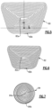
Figure 3 illustrates a portion of a jet head and a component that is to be drilled. -
Figure 4 illustrates 2-dimensional layers of a model of a hole. -
Figure 5 illustrates a spiral pattern of a layer of the model of the hole. -
Figure 6 illustrates another spiral pattern of a layer. -
Figure 7 illustrates a spiral pattern of a layer of a uniform section of the hole. -
Figure 8 illustrates a method of drilling a hole in a component. -
Figure 1 schematically illustrates agas turbine engine 20. Thegas turbine engine 20 is disclosed herein as a two-spool turbofan that generally incorporates afan section 22, acompressor section 24, a combustor section 26 and aturbine section 28. Thefan section 22 drives air along a bypass flow path B in a bypass duct defined within ahousing 15 such as a fan case or nacelle, and also drives air along a core flow path C for compression and communication into the combustor section 26 then expansion through theturbine section 28. Although depicted as a two-spool turbofan gas turbine engine in the disclosed non-limiting embodiment, it should be understood that the concepts described herein are not limited to use with two-spool turbofans as the teachings may be applied to other types of turbine engines including three-spool architectures. - The
exemplary engine 20 generally includes alow speed spool 30 and ahigh speed spool 32 mounted for rotation about an engine central longitudinal axis A relative to an enginestatic structure 36 viaseveral bearing systems 38. It should be understood thatvarious bearing systems 38 at various locations may alternatively or additionally be provided, and the location ofbearing systems 38 may be varied as appropriate to the application. - The
low speed spool 30 generally includes aninner shaft 40 that interconnects, a first (or low) pressure compressor 44 and a first (or low)pressure turbine 46. Theinner shaft 40 is connected to thefan 42 through a speed change mechanism, which in exemplarygas turbine engine 20 is illustrated as a gearedarchitecture 48 to drive afan 42 at a lower speed than thelow speed spool 30. Thehigh speed spool 32 includes anouter shaft 50 that interconnects a second (or high)pressure compressor 52 and a second (or high)pressure turbine 54. Acombustor 56 is arranged in theexemplary gas turbine 20 between thehigh pressure compressor 52 and thehigh pressure turbine 54. Amid-turbine frame 57 of the enginestatic structure 36 may be arranged generally between thehigh pressure turbine 54 and thelow pressure turbine 46. Themid-turbine frame 57 furthersupports bearing systems 38 in theturbine section 28. Theinner shaft 40 and theouter shaft 50 are concentric and rotate via bearingsystems 38 about the engine central longitudinal axis A which is collinear with their longitudinal axes. - The core airflow is compressed by the low pressure compressor 44 then the
high pressure compressor 52, mixed and burned with fuel in thecombustor 56, then expanded through thehigh pressure turbine 54 andlow pressure turbine 46. Themid-turbine frame 57 includesairfoils 59 which are in the core airflow path C. Theturbines low speed spool 30 andhigh speed spool 32 in response to the expansion. It will be appreciated that each of the positions of thefan section 22,compressor section 24, combustor section 26,turbine section 28, and fandrive gear system 48 may be varied. For example,gear system 48 may be located aft of the low pressure compressor, or aft of the combustor section 26 or even aft ofturbine section 28, andfan 42 may be positioned forward or aft of the location ofgear system 48. - The
engine 20 in one example is a high-bypass geared aircraft engine. In a further example, theengine 20 bypass ratio is greater than about six (6), with an example embodiment being greater than about ten (10), and can be less than or equal to about 18.0, or more narrowly can be less than or equal to 16.0. The gearedarchitecture 48 is an epicyclic gear train, such as a planetary gear system or other gear system, with a gear reduction ratio of greater than about 2.3. The gear reduction ratio may be less than or equal to 4.0. Thelow pressure turbine 46 has a pressure ratio that is greater than about five. The low pressure turbine pressure ratio can be less than or equal to 13.0, or more narrowly less than or equal to 12.0. In one disclosed embodiment, theengine 20 bypass ratio is greater than about ten (10:1), the fan diameter is significantly larger than that of the low pressure compressor 44, and thelow pressure turbine 46 has a pressure ratio that is greater than about five 5:1.Low pressure turbine 46 pressure ratio is pressure measured prior to an inlet oflow pressure turbine 46 as related to the pressure at the outlet of thelow pressure turbine 46 prior to an exhaust nozzle. The gearedarchitecture 48 may be an epicycle gear train, such as a planetary gear system or other gear system, with a gear reduction ratio of greater than about 2.3:1 and less than about 5:1. It should be understood, however, that the above parameters are only exemplary of one embodiment of a geared architecture engine and that the present invention is applicable to other gas turbine engines including direct drive turbofans. - A significant amount of thrust is provided by the bypass flow B due to the high bypass ratio. The
fan section 22 of theengine 20 is designed for a particular flight condition -- typically cruise at about 0.8 Mach and about 35,000 feet (10,668 meters). The flight condition of 0.8 Mach and 35,000 ft (10,668 meters), with the engine at its best fuel consumption - also known as "bucket cruise Thrust Specific Fuel Consumption ('TSFC')" - is the industry standard parameter of lbm of fuel being burned divided by lbf of thrust the engine produces at that minimum point. The engine parameters described above and those in this paragraph are measured at this condition unless otherwise specified. "Low fan pressure ratio" is the pressure ratio across the fan blade alone, without a Fan Exit Guide Vane ("FEGV") system. The low fan pressure ratio as disclosed herein according to one non-limiting embodiment is less than about 1.45, or more narrowly greater than or equal to 1.25. "Low corrected fan tip speed" is the actual fan tip speed in ft/sec divided by an industry standard temperature correction of [(Tram °R) / (518.7 °R)]0.5. The "Low corrected fan tip speed" as disclosed herein according to one non-limiting embodiment is less than about 1150.0 ft / second (350.5 meters/second), and can be greater than or equal to 1000.0 ft / second (304.8 meters/second). - Components in the
engine 20, such as but not limited to, turbine blades, turbine vanes, blade outer air seals, and combustor panels, include cooling holes. The cooling holes are used to emit relatively cool air to provide film cooling over the surface of the component. The cooling holes are most typically formed by a drilling operation. However, when the component is made of ceramic, such as monolithic ceramic or ceramic matrix composite (CMC), efficient drilling is challenging because ceramics are extremely hard and brittle. The drilling of relatively deep, small-diameter holes is especially challenging. For instance, both waterjet guided laser and abrasive waterjet use high-speed waterjets to either guide the laser or accelerate abrasive particles to remove material, respectively. After impinging the component, the waterjet rebounds as back-splash. The back-splash is turbulent and can interfere with the incoming waterjet, thereby disrupting the coherency of the waterjet and hindering efficient material removal. As will be described, the disclosed system and methodology facilitates removal of back-splash and more efficient drilling. -
Figure 2 illustrates an example system 60 for drilling holes in acomponent 62. Thecomponent 62 is made of ceramic (monolithic, CMC, or combination) but is not otherwise limited. As examples, thecomponent 62 may be a turbine blade, turbine vane, blade outer air seal, or combustor panel. The system 60 includes adrilling machine 64 that has a holder (generally at 66), ajet head 68, and anelectronic controller module 70. Theholder 66 serves to secure thecomponent 62 in a known position relative to thejet head 68. Theholder 66 may include one or more clamps, fasteners, clips, fixtures, adhesive, or the like that are used to mount (i.e., secure) thecomponent 62 in theholder 66. Thejet head 68 includes anozzle 68a for jetting a working liquid toward thecomponent 62. Most typically, the working liquid is water, but other liquids may also be used. The term "jetting" or variations thereof are used herein as reference to a forced discharge of a stream of the liquid from a nozzle. Thejet head 68 is of known construction for either liquid guided laser drilling or abrasive liquid jet drilling. - The
electronic controller module 70 is operably connected with theholder 66 and thejet head 68. In that regard, theelectronic controller module 70 includes hardware, such as one or more microprocessors, software, or both that is configured to control the operation of theholder 66 andjet head 68 and carry out the functions described in this disclosure. In the illustrated example, theelectronic controller module 70 is self-contained in thedrilling machine 64, although it is also contemplated that portions of theelectronic controller module 70 may be in one or more separate electronic devices, such as computers, tablets, or the like. One or both of theholder 66 and thejet head 68 are moveable, the movement of which is controlled by theelectronic controller module 70. In this regard, theholder 66 may be moved, thejet head 68 may be moved, or both theholder 66 and thejet head 68 may be moved, all of which serve to move thecomponent 62 relative to thejet head 68. -
Figure 3 illustrates a portion of thejet head 68 and thecomponent 62. Thecomponent 62 has atarget region 72 at which a hole is to be drilled. For instance, thetarget region 72 is the region of thecomponent 62 that contains material that will be removed to form the hole, i.e., a 3-dimensional projection of the hole. The type of hole is not particularly limited, except that the hole is deep relative to its maximum width. In the illustrated example, the hole to be drilled is a metering diffusion hole that has auniform section 72a and a tapered (diffusion)section 72b. Theuniform section 72a has aninlet end 74a and anoutlet end 74b. Theoutlet end 74b is also the inlet end of the taperedsection 72b. From theinlet end 74b the tapered section diverges to anoutlet end 74c. Theinlet end 74a will typically open to a core cavity or cooling passage in thecomponent 62, and theoutlet end 74c opens at the exterior, core gas path surface of thecomponent 62. - The
component 62 and thejet head 68 are situated relative to each other in adrilling arrangement 76. Thedrilling arrangement 76 refers to the setup of the relative positioning of thecomponent 62 and thejet head 68 in thedrilling machine 64. In thedrilling arrangement 76 thetarget region 72 is at a first position P1 that is vertically equal to or vertically above a second position P2 at which thejet head 68 is located. The terms "above" and "below" refer to vertical positions relative to horizontal reference planes. Thus, relative to a reference plane at P2, the plane at P1 is vertically equal to or vertically above the plane at P2. The position P1 is taken at the lowest vertical location of thetarget region 72, and the position P2 is taken at the centerline exit point of thenozzle 68a of thejet head 68. - The
jet head 68 andnozzle 68a are operable (by the electronic controller module 70) to jet aliquid stream 75. In thedrilling arrangement 76 thenozzle 68a is aimed at thetarget region 72 such that theliquid stream 75 impinges upon thetarget region 72 to remove material from thecomponent 62. As generally indicated at 75a, theliquid stream 75 contains either abrasive particles or a laser beam. As examples, the abrasive particles may be, but are not limited to, silicon carbide, boron carbide or diamond and may suspended in a slurry with a carrier such as water or oil. As theliquid stream 75 impinges thetarget region 72, the abrasive particles or the laser beam cause removal of material from thecomponent 62 to form the hole in thecomponent 62. Thecomponent 62 may be provided with a guard in the interior cavity that the hole opens into. The guard blocks the laser or abrasive particles once the drilling breaks through to the interior cavity. During drilling theliquid stream 75 rebounds off of thecomponent 62 as back-splash liquid, represented at 78. Thedrilling arrangement 76 causesgravitational draining 78a of the back-splash liquid 78 from thetarget region 72. That is, since the plane at P1 is vertically equal to or vertically above the plane at P2, the back-splash liquid tends to flow out of the hole as it is being drilled. This clears the back-splash liquid 78 from the hole to thereby reduce interference between the back-splash liquid 78 and theliquid stream 75. Theliquid stream 75 can thus remove material at a higher rate than if there was interference, reducing drilling time. While some gravitational flow of the back-splash liquid 78 can occur at a vertically equal arrangement, increased gravitational flow of the back-splash liquid 78 is expected when P1 is vertically above the plane at P2. This is due to the downward-sloped orientation of the hole as it is being drilled. - In the drilling operation, the
electronic controller module 70 moves thejet head 68 relative to thecomponent 62 such that theliquid stream 75 scans across thetarget region 72. For instance, thejet head 68 is moved such that theliquid stream 75 scans thetarget region 72 in a spiral pattern. An example,spiral pattern 80 is shown inFigure 4 , in which the line represents the path of theliquid stream 75 from an inner point 80a to anouter point 80b, or vice versa. For instance, the offset, or distance from one ring of thespiral pattern 80 to the next, may be set as a percentage (e.g., 95%, 90%, 85%, etc.) of the diameter of theliquid stream 75. - As an example, the
electronic controller module 70 is provided with a computerized 3-dimensional model of the hole that is to be drilled. For instance, the model is a program file for the tool path of the hole to be drilled. The model may be created outside of theelectronic controller module 70 and then uploaded to themodule 70 for operation of thedrilling machine 64. The model is divided into a series of successive 2-dimensional layers, represented inFigure 4 as layers L1 through L10. Thejet head 68 is moved such that theliquid stream 75 scans thetarget region 72 layer-by-layer through the series of successive 2-dimensional layers L1-L10 such that the abrasive particles or the laser beam causes removal of the material layer-by-layer. For instance, to form the taperedsection 72b of the hole, the initial layers L1 through L6 successively decrease in area. The subsequent layers L7 through L10 are successively equal in area to form theuniform section 72a. - To remove the material layer-by-layer, the
jet head 68 is moved such that theliquid stream 75 scans thetarget region 72 in a series of spiral patterns layer-by-layer L1 through L10. For example, thespiral pattern 80 inFigure 5 may correspond to layer L3, thespiral pattern 82 inFigure 6 may correspond to layer L4, and thespiral pattern 84 inFigure 7 may correspond to layers L7 through L10. - To facilitate maintaining efficiency, the
electronic controller module 70 also keeps theliquid stream 75 running continuously through the series of spiral patterns layer-by-layer. For example, thejet head 68 is moved along thespiral pattern 80 from point 80a to point 80b (i.e. an inside-out movement) for layer L3. Thepoint 80b then serves as anouter point 82b of thenext spiral pattern 82 for layer L4 and is the starting point for thejet head 68 to move along thespiral pattern 82 to theinner point 82a (i.e. an outside-in movement) for layer L4. Similarly, thejet head 68 may be moved inside-out along thespiral pattern 84 frompoint 84a to point 84b for layer L7 and then from 84b to 84a for layer L8. By use of the 2-dimensional layers from the model and alternating between inside-out movement of thejet head 68 and outside-in movement of thejet head 68 from layer-to-layer, theliquid stream 75 can be continuously run through the series of spiral patterns over layers L1 to L10. If the end point of one spiral pattern did not coincide with the location of the starting point of the next spiral pattern, then theliquid stream 75 would have to be stopped while it moves between those points, adding time to the drilling operation. The disclosed continuous approach thus avoids stoppages that would otherwise increase the overall duration of the drilling operation. The continuous movement of thejet head 68 also facilitates avoidance of interference back-splash 78. - The system 60 is also representative of a method 90 of machining the hole in the
component 62, as shown inFigure 8 . The method includessteps Step 90a includes mounting thecomponent 62 in thedrilling machine 64. For example, thecomponent 62 is clamped or fastened in theholder 66. Thecomponent 62 is mounted in the discloseddrilling arrangement 76 with regard to positions P1 and P2 discussed above. In some cases, the relative positions of thejet head 68 and/or theholder 66 may be adjusted via theelectronic controller module 70 in order to achieve the desireddrilling arrangement 76. Theelectronic controller module 70 then jets theliquid stream 75 from thejet head 68. Theliquid stream 75 impinges thetarget region 72 and the abrasive particles or the laser beam (75a) causes removal of material from thecomponent 62 at thetarget region 72 to form the hole in thecomponent 62. As discussed, thedrilling arrangement 76 causes gravitational draining of the back-splash liquid 78a from thetarget region 72 to reduce interference between the back-splash liquid 78a and theliquid stream 75. - Although a combination of features is shown in the illustrated examples, not all of them need to be combined to realize the benefits of various embodiments of this disclosure. In other words, a system designed according to an embodiment of this disclosure will not necessarily include all of the features shown in any one of the Figures or all of the portions schematically shown in the figures. Moreover, selected features of one example embodiment may be combined with selected features of other example embodiments.
- The preceding description is exemplary rather than limiting in nature. Variations and modifications to the disclosed examples may become apparent to those skilled in the art that do not necessarily depart from this disclosure. The scope of legal protection given to this disclosure can only be determined by studying the following claims.
Claims (15)
- A method of machining a hole in a component (62), the method comprising:mounting a component (62) in a drilling machine (64), the component (62) having a target region (72) at which a hole is to be drilled, and the component (62) and a jet head (68) being situated relative to each other in a drilling arrangement (76) in which the target region (72) is at a first position (PI) that is vertically equal to or vertically above a second position (P2) at which the jet head (68) is located; andjetting a liquid stream (75) from the jet head (68), the liquid stream (75) containing either abrasive particles (75a) or a laser beam (75a), the liquid stream (75) impinging the target region (72), the abrasive particles (75a) or the laser beam (75a) causing removal of material from the component (62) at the target region (72) to form the hole in the component (62), the liquid stream (75) rebounding off of the component (62) as back-splash liquid (78), and the drilling arrangement (76) causing gravitational draining (78a) of the back-splash liquid (78) from the target region (72) to reduce interference between the back-splash liquid (78) and the liquid stream (75).
- The method as recited in claim 1, including, relative to the component (62), moving the jet head (68) such that the liquid stream (75) scans across the target region (72) and/or such that the liquid stream (75) scans the target region (72) in a spiral pattern (80, 82, 84).
- The method as recited in claim 1 or 2, including providing a computerized 3-dimensional model of the hole that is to be drilled, dividing the model into a series of successive 2-dimensional layers (L1-L10), and relative to the component (62) moving the jet head (68) such that the liquid stream (75) scans the target region layer-by-layer of the series of successive 2-dimensional layers (L1-L10) such that the abrasive particles (75a) or the laser beam (75a) causes removal of the material layer-by-layer.
- The method as recited in claim 3, wherein initial layers (L1-L6) of the series of successive 2-dimensional layers (L1-L10) successively decrease in area such that the hole includes a tapered section (72b), wherein after the initial layers (L1-L6), subsequent layers (L7-L10) of the series of successive 2-dimensional layers (L1-L10) are optionally successively equal in area such that the hole includes a uniform section (72a).
- The method as recited in claim 3 or 4, including, relative to the component (62), moving the jet head (68) such that the liquid stream (75) scans the target region (72) in a series of spiral patterns (80, 82, 84) layer-by-layer of the series of successive 2-dimensional layers (L1-L10).
- The method as recited in claim 5, wherein the liquid stream (75) is continuous through the series of spiral patterns (80, 82, 84).
- The method as recited in claim 5 or 6, wherein the spiral patterns (80, 82, 84) alternate between inside-out movement of the jet head (68) and outside-in movement of the jet head (68).
- A system (60) for machining a hole in a component (62), the system (60) comprising:a drilling machine (64) having a holder (66) and a jet head (68), the holder (66) operable to mount a component (62) that has a target region (72) at which a hole is to be drilled, the holder (66) and the jet head (68) situated or capable of being situated relative to each other in a drilling arrangement (76) in which the target region (72) is at a first position (PI) that is vertically equal to or vertically above a second position (P2) at which the jet head (68) is located; andthe drilling machine (64) operable to jet a liquid stream (75) from the jet head (68), the liquid stream (75) containing either abrasive particles (75a) or a laser beam (75a), the liquid stream (75) to impinge the target region (72) such that the abrasive particles (75a) or the laser beam (75a) causes removal of material from the component (62) at the target region (72) to form the hole in the component (62), where the liquid stream (75) rebounds off of the component (62) as back-splash liquid (78), and the drilling arrangement (76) causes gravitational draining (78a) of the back-splash liquid (78) from the target region (72) to reduce interference between the back-splash liquid (78) and the liquid stream (75).
- The system (60) as recited in claim 8, wherein the drilling machine (64) includes an electronic controller (70) that is configured, relative to the component (62), to move the jet head (68) such that the liquid stream (75) scans across the target region (72) and/or such that the liquid stream (75) scans the target region in a spiral pattern (80, 82, 84).
- The system (60) as recited in claim 9, wherein the controller (70) includes a computerized 3-dimensional model of the hole that is to be drilled, the model is divided into a series of successive 2-dimensional layers (L1-L10), and the controller (70) is configured to move the jet head (68) such that the liquid stream (75) scans the target region (72) layer-by-layer of the series of successive 2-dimensional layers (L1-L10) such that the abrasive particles (75a) or the laser beam (75a) causes removal of the material layer-by-layer.
- The system (60) as recited in claim 10, wherein initial layers (L1-L6) of the series of successive 2-dimensional layers (L1-L10) successively decrease in area such that the hole includes a tapered section (72b).
- The system (60) as recited in claim 11, wherein after the initial layers (L1-L6), subsequent layers (L7-L10) of the series of successive 2-dimensional layers (L1-L10) are successively equal in area such that the hole includes a uniform section (72a).
- The system (60) as recited in any of claims 10 to 12, wherein the controller (70) is configured to move the jet head (68) such that the liquid stream (75) scans the target region (72) in a series of spiral patterns (80, 82, 84) layer-by-layer of the series of successive 2-dimensional layers (L1-L10).
- The system (60) as recited in claim 13, wherein controller (70) is operable to continuously maintain the liquid stream (75) throughout the series of spiral patterns (80, 82, 84) and/or wherein the controller (70) is configured to alternate the spiral patterns (80, 82, 84) between inside-out movement of the jet head (68) and outside-in movement of the jet head (68).
- The method or system (60) as recited in any preceding claim, wherein the first position (P1) is vertically above the second position (P2).
Applications Claiming Priority (1)
| Application Number | Priority Date | Filing Date | Title |
|---|---|---|---|
| US17/406,536 US12103136B2 (en) | 2021-08-19 | 2021-08-19 | Method and system for drilling ceramic |
Publications (1)
| Publication Number | Publication Date |
|---|---|
| EP4137271A1 true EP4137271A1 (en) | 2023-02-22 |
Family
ID=82839431
Family Applications (1)
| Application Number | Title | Priority Date | Filing Date |
|---|---|---|---|
| EP22188828.2A Pending EP4137271A1 (en) | 2021-08-19 | 2022-08-04 | Method and system for drilling ceramic material |
Country Status (2)
| Country | Link |
|---|---|
| US (1) | US12103136B2 (en) |
| EP (1) | EP4137271A1 (en) |
Citations (10)
| Publication number | Priority date | Publication date | Assignee | Title |
|---|---|---|---|---|
| US3435560A (en) * | 1965-10-18 | 1969-04-01 | Us Navy | Apparatus for producing small holes |
| US5372540A (en) * | 1993-07-13 | 1994-12-13 | The Laitram Corporation | Robot cutting system |
| GB2389330A (en) * | 2003-03-31 | 2003-12-10 | M J Technologies Ltd | Machining of cooling air holes in gas turbine components |
| WO2006100798A1 (en) * | 2005-03-18 | 2006-09-28 | Shibuya Kogyo Co., Ltd. | Hybrid laser processing system |
| US8262802B2 (en) * | 2006-05-27 | 2012-09-11 | Rolls-Royce, Plc | Method of removing deposits |
| US20140024295A1 (en) * | 2012-07-19 | 2014-01-23 | Flow International Corporation | Fluid jet receiving receptacles and related fluid jet cutting systems and methods |
| US20150184517A1 (en) * | 2013-09-26 | 2015-07-02 | General Electric Company | Airfoils with low-angle holes and methods for drilling same |
| DE102014204881A1 (en) * | 2014-03-17 | 2015-09-17 | Siemens Aktiengesellschaft | Removal strategy for material removal |
| EP3460191A1 (en) * | 2017-09-21 | 2019-03-27 | United Technologies Corporation | Gas turbine engine component with cooling holes having variable roughness |
| EP3521704A2 (en) * | 2018-02-06 | 2019-08-07 | United Technologies Corporation | Diffusing hole for rail effusion |
Family Cites Families (11)
| Publication number | Priority date | Publication date | Assignee | Title |
|---|---|---|---|---|
| US4375740A (en) * | 1978-05-25 | 1983-03-08 | Jpd Manufacturing Limited | Portable abrading cabinet device for recycling abrasive blasting system |
| US4651476A (en) * | 1986-05-07 | 1987-03-24 | Flow Systems, Inc. | Compact receptacle with automatic feed for dissipating a high-velocity fluid jet |
| US5860849A (en) * | 1997-03-25 | 1999-01-19 | Huffman Corp | Liquid abrasive jet focusing tube for making non-perpendicular cuts |
| US7186167B2 (en) | 2004-04-15 | 2007-03-06 | United Technologies Corporation | Suspended abrasive waterjet hole drilling system and method |
| GB0807964D0 (en) * | 2008-05-02 | 2008-06-11 | Rolls Royce Plc | A method of fluid jet machining |
| DE102011078076A1 (en) * | 2011-06-24 | 2012-12-27 | Dürr Ecoclean GmbH | Nozzle module and cleaning device with nozzle module |
| US9573289B2 (en) | 2013-10-28 | 2017-02-21 | Flow International Corporation | Fluid jet cutting systems |
| US9446501B2 (en) | 2014-12-31 | 2016-09-20 | Spirit Aerosystems, Inc. | Method and apparatus for abrasive stream perforation |
| US11679454B2 (en) * | 2017-08-31 | 2023-06-20 | The Boeing Company | Portable cavitation peening method and apparatus |
| US20210154799A1 (en) * | 2019-11-25 | 2021-05-27 | Synticos, LLC | Abrasive suspension jet cutting system having reduced system wear and process materials reclamation |
| US11504794B2 (en) * | 2020-01-02 | 2022-11-22 | The Esab Group Inc. | Methods and apparatus for forming a pierce hole in a workpiece |
-
2021
- 2021-08-19 US US17/406,536 patent/US12103136B2/en active Active
-
2022
- 2022-08-04 EP EP22188828.2A patent/EP4137271A1/en active Pending
Patent Citations (10)
| Publication number | Priority date | Publication date | Assignee | Title |
|---|---|---|---|---|
| US3435560A (en) * | 1965-10-18 | 1969-04-01 | Us Navy | Apparatus for producing small holes |
| US5372540A (en) * | 1993-07-13 | 1994-12-13 | The Laitram Corporation | Robot cutting system |
| GB2389330A (en) * | 2003-03-31 | 2003-12-10 | M J Technologies Ltd | Machining of cooling air holes in gas turbine components |
| WO2006100798A1 (en) * | 2005-03-18 | 2006-09-28 | Shibuya Kogyo Co., Ltd. | Hybrid laser processing system |
| US8262802B2 (en) * | 2006-05-27 | 2012-09-11 | Rolls-Royce, Plc | Method of removing deposits |
| US20140024295A1 (en) * | 2012-07-19 | 2014-01-23 | Flow International Corporation | Fluid jet receiving receptacles and related fluid jet cutting systems and methods |
| US20150184517A1 (en) * | 2013-09-26 | 2015-07-02 | General Electric Company | Airfoils with low-angle holes and methods for drilling same |
| DE102014204881A1 (en) * | 2014-03-17 | 2015-09-17 | Siemens Aktiengesellschaft | Removal strategy for material removal |
| EP3460191A1 (en) * | 2017-09-21 | 2019-03-27 | United Technologies Corporation | Gas turbine engine component with cooling holes having variable roughness |
| EP3521704A2 (en) * | 2018-02-06 | 2019-08-07 | United Technologies Corporation | Diffusing hole for rail effusion |
Also Published As
| Publication number | Publication date |
|---|---|
| US20230056508A1 (en) | 2023-02-23 |
| US12103136B2 (en) | 2024-10-01 |
Similar Documents
| Publication | Publication Date | Title |
|---|---|---|
| EP2937513B1 (en) | Method of forming a component | |
| EP3054113B1 (en) | Impingement cooled component and corresponding method for cooling a component | |
| EP3009599A1 (en) | Gas turbine engine component with film cooling hole feature | |
| EP4201580A1 (en) | Fabrication of cooling holes using laser machining and ultrasonic machining | |
| EP3043027B1 (en) | Gas turbine engine component with conformal fillet cooling path | |
| US12607129B2 (en) | Attachment region for CMC components | |
| US10982552B2 (en) | Gas turbine engine component with film cooling hole | |
| EP3034791A1 (en) | Heat transfer pedestals with flow guide features | |
| EP3623580A1 (en) | Airfoil with geometrically segmented coating section having mechanical secondary bonding feature | |
| EP3034793A1 (en) | Gas turbine engine component with increased cooling capacity | |
| US11149573B2 (en) | Airfoil with seal between end wall and airfoil section | |
| US10370977B2 (en) | Apparatus for creating a film cooled article for a gas turbine engine | |
| US9957814B2 (en) | Gas turbine engine component with film cooling hole with accumulator | |
| EP4137271A1 (en) | Method and system for drilling ceramic material | |
| EP3323986B1 (en) | Airfoil with geometrically segmented coating section | |
| US12304004B2 (en) | Multi-step method for machining blind opening in ceramic component | |
| US11959396B2 (en) | Gas turbine engine article with cooling holes for mitigating recession | |
| EP4282849B1 (en) | Laser treatment of machined ceramic surface for sealing | |
| EP4403748A1 (en) | Sealing between ceramic and metallic component of a gas turbine engine | |
| EP3099976A1 (en) | Cooling flow for leading panel in a gas turbine engine combustor |
Legal Events
| Date | Code | Title | Description |
|---|---|---|---|
| PUAI | Public reference made under article 153(3) epc to a published international application that has entered the european phase |
Free format text: ORIGINAL CODE: 0009012 |
|
| STAA | Information on the status of an ep patent application or granted ep patent |
Free format text: STATUS: THE APPLICATION HAS BEEN PUBLISHED |
|
| AK | Designated contracting states |
Kind code of ref document: A1 Designated state(s): AL AT BE BG CH CY CZ DE DK EE ES FI FR GB GR HR HU IE IS IT LI LT LU LV MC MK MT NL NO PL PT RO RS SE SI SK SM TR |
|
| STAA | Information on the status of an ep patent application or granted ep patent |
Free format text: STATUS: REQUEST FOR EXAMINATION WAS MADE |
|
| 17P | Request for examination filed |
Effective date: 20230725 |
|
| RBV | Designated contracting states (corrected) |
Designated state(s): AL AT BE BG CH CY CZ DE DK EE ES FI FR GB GR HR HU IE IS IT LI LT LU LV MC MK MT NL NO PL PT RO RS SE SI SK SM TR |
|
| RAP3 | Party data changed (applicant data changed or rights of an application transferred) |
Owner name: RTX CORPORATION |
|
| STAA | Information on the status of an ep patent application or granted ep patent |
Free format text: STATUS: EXAMINATION IS IN PROGRESS |
|
| 17Q | First examination report despatched |
Effective date: 20240823 |