EP4137258A1 - Cutting system, display system, processing device, processing method, and processing program - Google Patents
Cutting system, display system, processing device, processing method, and processing program Download PDFInfo
- Publication number
- EP4137258A1 EP4137258A1 EP20931242.0A EP20931242A EP4137258A1 EP 4137258 A1 EP4137258 A1 EP 4137258A1 EP 20931242 A EP20931242 A EP 20931242A EP 4137258 A1 EP4137258 A1 EP 4137258A1
- Authority
- EP
- European Patent Office
- Prior art keywords
- cutting
- dimensional data
- unit
- cutting tool
- sensors
- Prior art date
- Legal status (The legal status is an assumption and is not a legal conclusion. Google has not performed a legal analysis and makes no representation as to the accuracy of the status listed.)
- Granted
Links
Images




Classifications
-
- G—PHYSICS
- G05—CONTROLLING; REGULATING
- G05B—CONTROL OR REGULATING SYSTEMS IN GENERAL; FUNCTIONAL ELEMENTS OF SUCH SYSTEMS; MONITORING OR TESTING ARRANGEMENTS FOR SUCH SYSTEMS OR ELEMENTS
- G05B19/00—Program-control systems
- G05B19/02—Program-control systems electric
- G05B19/18—Numerical control [NC], i.e. automatically operating machines, in particular machine tools, e.g. in a manufacturing environment, so as to execute positioning, movement or co-ordinated operations by means of program data in numerical form
- G05B19/406—Numerical control [NC], i.e. automatically operating machines, in particular machine tools, e.g. in a manufacturing environment, so as to execute positioning, movement or co-ordinated operations by means of program data in numerical form characterised by monitoring or safety
- G05B19/4065—Monitoring tool breakage, life or condition
-
- B—PERFORMING OPERATIONS; TRANSPORTING
- B23—MACHINE TOOLS; METAL-WORKING NOT OTHERWISE PROVIDED FOR
- B23C—MILLING
- B23C5/00—Milling-cutters
- B23C5/02—Milling-cutters characterised by the shape of the cutter
- B23C5/10—Shank-type cutters, i.e. with an integral shaft
- B23C5/109—Shank-type cutters, i.e. with an integral shaft with removable cutting inserts
-
- B—PERFORMING OPERATIONS; TRANSPORTING
- B23—MACHINE TOOLS; METAL-WORKING NOT OTHERWISE PROVIDED FOR
- B23C—MILLING
- B23C9/00—Details or accessories so far as specially adapted to milling machines or cutter
-
- B—PERFORMING OPERATIONS; TRANSPORTING
- B23—MACHINE TOOLS; METAL-WORKING NOT OTHERWISE PROVIDED FOR
- B23Q—DETAILS, COMPONENTS, OR ACCESSORIES FOR MACHINE TOOLS, e.g. ARRANGEMENTS FOR COPYING OR CONTROLLING; MACHINE TOOLS IN GENERAL CHARACTERISED BY THE CONSTRUCTION OF PARTICULAR DETAILS OR COMPONENTS; COMBINATIONS OR ASSOCIATIONS OF METAL-WORKING MACHINES, NOT DIRECTED TO A PARTICULAR RESULT
- B23Q17/00—Arrangements for observing, indicating or measuring on machine tools
- B23Q17/09—Arrangements for observing, indicating or measuring on machine tools for indicating or measuring cutting pressure or for determining cutting-tool condition, e.g. cutting ability, load on tool
- B23Q17/0952—Arrangements for observing, indicating or measuring on machine tools for indicating or measuring cutting pressure or for determining cutting-tool condition, e.g. cutting ability, load on tool during machining
- B23Q17/0966—Arrangements for observing, indicating or measuring on machine tools for indicating or measuring cutting pressure or for determining cutting-tool condition, e.g. cutting ability, load on tool during machining by measuring a force on parts of the machine other than a motor
-
- B—PERFORMING OPERATIONS; TRANSPORTING
- B23—MACHINE TOOLS; METAL-WORKING NOT OTHERWISE PROVIDED FOR
- B23C—MILLING
- B23C2260/00—Details of constructional elements
- B23C2260/76—Sensors
-
- G—PHYSICS
- G05—CONTROLLING; REGULATING
- G05B—CONTROL OR REGULATING SYSTEMS IN GENERAL; FUNCTIONAL ELEMENTS OF SUCH SYSTEMS; MONITORING OR TESTING ARRANGEMENTS FOR SUCH SYSTEMS OR ELEMENTS
- G05B2219/00—Program-control systems
- G05B2219/30—Nc systems
- G05B2219/37—Measurements
- G05B2219/37087—Cutting forces
-
- G—PHYSICS
- G05—CONTROLLING; REGULATING
- G05B—CONTROL OR REGULATING SYSTEMS IN GENERAL; FUNCTIONAL ELEMENTS OF SUCH SYSTEMS; MONITORING OR TESTING ARRANGEMENTS FOR SUCH SYSTEMS OR ELEMENTS
- G05B2219/00—Program-control systems
- G05B2219/30—Nc systems
- G05B2219/37—Measurements
- G05B2219/37274—Strain gauge
-
- G—PHYSICS
- G05—CONTROLLING; REGULATING
- G05B—CONTROL OR REGULATING SYSTEMS IN GENERAL; FUNCTIONAL ELEMENTS OF SUCH SYSTEMS; MONITORING OR TESTING ARRANGEMENTS FOR SUCH SYSTEMS OR ELEMENTS
- G05B2219/00—Program-control systems
- G05B2219/30—Nc systems
- G05B2219/37—Measurements
- G05B2219/37355—Cutting, milling, machining force
-
- G—PHYSICS
- G05—CONTROLLING; REGULATING
- G05B—CONTROL OR REGULATING SYSTEMS IN GENERAL; FUNCTIONAL ELEMENTS OF SUCH SYSTEMS; MONITORING OR TESTING ARRANGEMENTS FOR SUCH SYSTEMS OR ELEMENTS
- G05B2219/00—Program-control systems
- G05B2219/30—Nc systems
- G05B2219/41—Servomotor, servo controller till figures
- G05B2219/41376—Tool wear, flank and crater, estimation from cutting force
-
- G—PHYSICS
- G05—CONTROLLING; REGULATING
- G05B—CONTROL OR REGULATING SYSTEMS IN GENERAL; FUNCTIONAL ELEMENTS OF SUCH SYSTEMS; MONITORING OR TESTING ARRANGEMENTS FOR SUCH SYSTEMS OR ELEMENTS
- G05B2219/00—Program-control systems
- G05B2219/30—Nc systems
- G05B2219/50—Machine tool, machine tool null till machine tool work handling
- G05B2219/50203—Tool, monitor condition tool
-
- G—PHYSICS
- G05—CONTROLLING; REGULATING
- G05B—CONTROL OR REGULATING SYSTEMS IN GENERAL; FUNCTIONAL ELEMENTS OF SUCH SYSTEMS; MONITORING OR TESTING ARRANGEMENTS FOR SUCH SYSTEMS OR ELEMENTS
- G05B2219/00—Program-control systems
- G05B2219/30—Nc systems
- G05B2219/50—Machine tool, machine tool null till machine tool work handling
- G05B2219/50327—As function of cutting forces
Definitions
- the present disclosure relates to a cutting system, a display system, a processing apparatus, a processing method, and a processing program.
- Patent Literature 1 Japanese Unexamined Patent Application Publication No. 2015-77658 discloses the following state measurement apparatus. That is, the state measuring apparatus is a state measuring apparatus that measures a state of a cutting tool during a cutting process, wherein the cutting tool is configured by a rotating body that has one or more cutting edges and machines a workpiece by bringing the cutting edges into contact with the workpiece while rotating, and includes a measurement unit that is attached to the cutting edge or a vicinity of the cutting edge and measures a state of the cutting edges, an AD converter attached to the cutting tool and configured to acquire a measurement value measured by the measurement unit at a predetermined sampling rate and perform AD conversion, a transmission unit configured to transmit the acquired measurement value using digital wireless communication each time the measurement value is acquired from the AD converter, and a monitor apparatus provided outside the cutting tool, and the monitoring apparatus includes a reception unit that receives the measurement value transmitted by the transmission unit, and a data management unit that causes a display unit to display the measurement value and causes a storage unit to store the measurement value each time the measurement value
- An aspect of the present disclosure can be realized not only as a cutting system including such a characteristic processing unit but also as a semiconductor integrated circuit that realizes a part or all of the cutting system. Further, one aspect of the present disclosure can be realized not only as a processing apparatus including such a characteristic processing unit but also as a semiconductor integrated circuit that realizes a part or all of the processing apparatus.
- Patent Literature 1 a technique capable of realizing an excellent function related to a cutting blade in a cutting tool is desired.
- the present disclosure has been made to solve the above-described problem, and an object thereof is to provide a cutting system, a display system, a processing apparatus, a processing method, and a processing program capable of realizing excellent functions related to a cutting blade in a cutting tool.
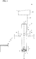
- FIG. 1 is a diagram showing a configuration of a cutting system according to an embodiment of the present disclosure.
- a cutting system 301 includes a cutting tool 101 for milling, a plurality of strain sensors 20, and a processing apparatus 201.
- Cutting system 301 is an example of a display system.
- Processing apparatus 201 is an example of a processing unit in cutting system 301.
- Cutting tool 101 performs a cutting process using two or more cutting blades.
- Cutting tool 101 is, for example, an end mill used in a machine tool such as a milling machine, and is used for milling a cutting object made of metal or the like.
- Cutting tool 101 is, for example, an indexable end mill.
- Cutting tool 101 is used in a state of being held by a tool holder 210 such as an arbor.
- Tool holder 210 is attached to a main shaft 220 of the machine tool.
- Main shaft 220 has a columnar shape and applies a rotational force to tool holder 210.
- Tool holder 210 is a columnar member disposed on an extension line of main shaft 220. Specifically, an upper end portion of tool holder 210 is held by main shaft 220. Further, a lower end portion of tool holder 210 holds cutting tool 101.
- Cutting tool 101 includes a shank portion 11, a housing 24, a battery 22, a wireless communication apparatus 23, and a blade attaching portion 12.
- housing 24 is indicated by a two dot chain line which is an imaginary line.
- Blade attaching portion 12 is provided closer to the distal end than shank portion 11 in cutting tool 101.
- Blade attaching portion 12 includes, for example, four blade fixing portions 13. A cutting blade 14 is attached to each blade fixing portion 13.
- strain sensor 20 is provided in shank portion 11 of cutting tool 101. More specifically, strain sensor 20 is attached to the peripheral surface of shank portion 11 via, for example, an adhesive or a glue.
- Housing 24 houses strain sensor 20 attached to shank portion 11. Specifically, housing 24 includes a bottom plate portion and a side wall portion (not shown). Housing 24 covers strain sensor 20 from below and from the side.
- Battery 22 and wireless communication apparatus 23 are housed in housing 24.
- battery 22 and wireless communication apparatus 23 are fixed to the bottom plate portion or the side wall portion of housing 24.
- Wireless communication apparatus 23 includes a communication circuit such as a communication integrated circuit (IC), for example.
- IC communication integrated circuit
- Battery 22 is connected to strain sensor 20 and wireless communication apparatus 23 via a power line (not shown). Battery 22 supplies power to strain sensor 20 and wireless communication apparatus 23 via the power line.
- the power line is provided with a switch for switching on and off of power supply.
- cutting system 301 includes strain sensors 20, and a number of which is irrelevant to the number of cutting blades 14 in cutting tool 101. Further, for example, cutting system 301 includes strain sensors 20, a number of which is less than the number of cutting blades 14 in cutting tool 101. More specifically, cutting system 301 includes, for example, three strain sensors 20.
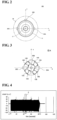
- FIG. 2 is a cross-sectional view showing a configuration of a cutting tool according to an embodiment of the present disclosure.
- FIG. 2 is a cross-sectional view viewing from the arrow direction of line II-II in FIG. 1 .
- strain sensors 20A, 20B, and 20C are provided on shank portion 11 as strain sensors 20.
- Strain sensor 20B is provided at a position shifted by 90° from the position at which strain sensor 20C is provided in the circumferential direction of shank portion 11.
- Strain sensor 20A is provided at a position shifted by 90° from the position at which strain sensor 20B is provided in the circumferential direction of shank portion 11.
- Strain sensors 20A and 20C are provided at positions that are point-symmetric with respect to a rotation axis 17 of shank portion 11.
- strain sensors 20A, 20B, and 20C may be provided at the same position in the direction along rotation axis 17 of shank portion 11, or may be provided at positions different from each other.
- Strain sensors 20A, 20B, and 20C may be provided on the peripheral surface of shank portion 11 as described above, for example, regardless of the position of blade attaching portion 12. That is, strain sensors 20A, 20B, and 20C do not need to be provided at positions along rotation axis 17 from blade fixing portion 13 on the peripheral surface of shank portion 11.
- a direction from rotation axis 17 to a position where strain sensor 20A is provided is referred to as an X direction
- a direction from rotation axis 17 to the position where strain sensor 20B is provided is referred to as a Y direction.
- FIG. 3 is an arrow view showing a configuration of a cutting tool according to an embodiment of the present disclosure.
- FIG. 3 is an arrow view seen from the direction III in FIG. 1 .
- blade attaching portion 12 includes blade fixing portions 13A, 13B, 13C, and 13D as blade fixing portions 13.
- Blade fixing portions 13A, 13B, 13C, and 13D are provided in this order at positions shifted by 90° in the clockwise direction in the circumferential direction of blade attaching portion 12.
- Cutting blades 14A, 14B, 14C and 14D are attached to blade fixing portions 13A, 13B, 13C and 13D, respectively as cutting blades 14.
- Cutting blade 14 is, for example, an indexable insert. Cutting blade 14 is attached to blade fixing portion 13, for example by screwing. Note that cutting blade 14 may be fixed to blade fixing portion 13 by means other than screwing. Further, cutting tool 101 may be a so-called solid end mill including cutting blade 14 integrated with shank portion 11 instead of blade attaching portion 12.
- Strain sensor 20 measures a physical quantity indicating a state regarding a load of cutting tool 101 at a time of the cutting process. More specifically, strain sensor 20 measures a strain ⁇ of shank portion 11 in a direction parallel to rotation axis 17 as the physical quantity indicative of the load-related state of cutting tool 101 at the time of the cutting process.
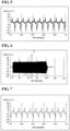
- FIGS. 4 to 7 are diagrams showing an example of measurement results of strain sensors acquired by a wireless communication unit in a processing apparatus according to an embodiment of the present disclosure.
- FIG. 4 is a time-series measurement results of strain ⁇ by strain sensor 20A
- FIG. 5 is an enlarged view of region A in FIG. 4
- FIG. 6 is a time-series measurement results of strain ⁇ by strain sensor 20B
- FIG. 7 is an enlarged view of region B in FIG. 6 .
- the horizontal axis represents time [seconds]
- the vertical axis represents strain [ ⁇ ].
- strain sensor 20 measures strain ⁇ in a period from time ts, which is a start time of the cutting process, to time te, which is an end time of the cutting process, and transmits an analog signal having a level corresponding to strain ⁇ to wireless communication apparatus 23 via a signal line (not shown), for example.
- Wireless communication apparatus 23 performs analog-to-digital (AD) conversion on the analog signal received from strain sensor 20 at a predetermined sampling period, and generates a sensor measurement value that is a digital value after the conversion. More specifically, wireless communication apparatus 23 generates the sensor measurement value sx by performing AD conversion on the analog signal of strain ⁇ received from strain sensor 20A, generates the sensor measurement value sy by performing AD conversion on the analog signal of strain ⁇ received from strain sensor 20B, and generates the sensor measurement value sr by performing AD conversion on the analog signal of strain ⁇ received from strain sensor 20C.
- AD analog-to-digital
- Wireless communication apparatus 23 adds a time stamp indicating a sampling timing to each of the generated sensor measurement values sx, sy, sr, and stores the sensor measurement values sx, sy, sr to which the time stamps are added in a storage unit (not shown).
- Wireless communication apparatus 23 acquires one or a plurality of sets of the sensor measurement values sx, sy, sr from the storage unit, generates a wireless signal including acquired sensor measurement values sx, sy, sr and an identification information of corresponding strain sensor 20, and transmits the generated wireless signal to processing apparatus 201, for example, in a predetermined cycle.
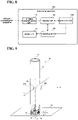
- FIG. 8 is a diagram showing a configuration of a processing apparatus in a cutting system according to an embodiment of the present disclosure.
- processing apparatus 201 includes a wireless communication unit 110, a generation unit 120, a processing unit 130, a storage unit 140, and a display unit 150.
- Wireless communication unit 110 is an example of an acquisition unit.
- Processing unit 130 is an example of a detection unit and an example of a display processing unit.
- Wireless communication unit 110 is realized by a communication circuit such as a communication IC, for example.
- Generation unit 120 and processing unit 130 are realized by processors such as a central processing unit (CPU) and a digital signal processor (DSP), for example.
- Storage unit 140 is, for example, a nonvolatile memory.
- Display unit 150 is, for example, a display. Note that display unit 150 may be provided outside processing apparatus 201.
- Wireless communication unit 110 acquires measurement results by strain sensor 20 that measures the physical quantity indicating the state related to the load of cutting tool 101 at a time of the cutting process.
- wireless communication unit 110 performs wireless communication with wireless communication apparatus 23 in cutting tool 101.
- Wireless communication apparatus 23 and wireless communication unit 110 perform wireless communication using a communication protocol such as ZigBee conforming to IEEE802.15.4, Bluetooth (trade mark) conforming to IEEE802.15.1, and UWB (Ultra Wide Band) conforming to IEEE802.15.3a.
- a communication protocol other than the above may be used between wireless communication apparatus 23 and wireless communication unit 110.
- Wireless communication unit 110 acquires the sensor measurement values sx, sy, sr and the identification information from the wireless signal received from wireless communication apparatus 23 in cutting tool 101. Then, wireless communication unit 110 stores the sensor measurement values sx, sy, sr in storage unit 140 in association with the identification information.
- Generation unit 120 generates two-dimensional data D for each measurement timing related to the load in two directions on a plane perpendicular to rotation axis 17 of shank portion 11 in cutting tool 101 based on the measurement results by each strain sensor 20 at a plurality of measurement timings, which are acquired by wireless communication unit 110.
- generation unit 120 When the sensor measurement values sx, sy, and sr are stored in storage unit 140 by wireless communication unit 110, generation unit 120 generates two-dimensional data D based on the sensor measurement values sx, sy, and sr stored in storage unit 140.
- FIG. 9 is a perspective view schematically showing a cutting tool according to an embodiment of the present disclosure.
- a load i.e., a cutting force F [N] is applied from the cutting object to cutting blade 14.
- generation unit 120 generates, based on sensor measurement values sx, sy, and sr, two-dimensional data D indicating a moment Mx generated by the load in the X direction and a moment My generated by the load in the Y direction in a cutting resistance acting surface 18 which is a plane perpendicular to rotation axis 17 of shank portion 11 and which passes through cutting blade 14.
- storage unit 140 stores a conversion formula for converting the sensor measurement values sx, sy, and sr into moments Mx and My.
- the conversion formula is created in advance using a technique described in Patent Literature 5 and Patent Literature 6. More specifically, the conversion formula is a conversion matrix created in advance based on the sensor measurement values sx, sy, and sr obtained when a known load is applied to cutting tool 101.
- Generation unit 120 generates two-dimensional data D indicating moments Mx and My based on the sensor measurement values sx, sy, sr and the transformation matrix in storage unit 140.
- Generation unit 120 sequentially generates two-dimensional data D. More specifically, generation unit 120 generates two-dimensional data D each time the sensor measurement values sx, sy, and sr are stored in storage unit 140 by wireless communication unit 110, and outputs the generated two-dimensional data D to processing unit 130.
- generation unit 120 may be configured to generate, based on sensor measurement values sx, sy, sr without using the conversion matrix, two-dimensional data D indicating strain ⁇ at the position where strain sensor 20A is provided and strain ⁇ at the position where strain sensor 20B is provided.
- FIG. 10 is a diagram showing an example of two-dimensional data generated by a generation unit in a processing apparatus according to an embodiment of the present disclosure.
- about 8000 pieces of two-dimensional data D generated based on the sensor measurement values sx, sy, sr in a period before the abnormality occurs in cutting blade 14 are plotted on a two-dimensional coordinate C (C1) in which the vertical axis is moment Mx [Nm] and the horizontal axis is moment My [Nm].
- FIG. 11 is a diagram showing another example of two-dimensional data generated by a generation unit in a processing apparatus according to the embodiment of the present disclosure.
- about 8000 pieces of two-dimensional data D generated based on the sensor measurement values sx, sy, sr in a period after certain cutting blade 14 is lacked are plotted on a two-dimensional coordinate C (C2) in which the vertical axis is moment Mx [Nm] and the horizontal axis is moment My [Nm].
- Processing unit 130 detects abnormality such as a lack of cutting blade 14 by analyzing two-dimensional data D generated by generation unit 120.
- processing unit 130 performs classification processing which is processing of classifying each two-dimensional data D generated by generation unit 120 into any one of a plurality of unit regions A whose number is equal to or greater than the number of cutting blades 14 in the plane perpendicular to rotation axis 17. For example, as classification processing, processing unit 130 classifies each two-dimensional data D into any one of a plurality of unit regions A in two-dimensional coordinate C1. Then, processing unit 130 performs detection processing which is a process of detecting the abnormality of cutting blade 14 based on two-dimensional data D for each unit region.
- Unit region A is each region when 360 degrees is divided into n.
- n is an integer equal to or greater than the number of cutting blades 14.
- unit region A is each region when a plane perpendicular to rotation axis 17 is equally divided into n regions around rotation axis 17 by a plurality of straight lines that are on the plane and pass through rotation axis 17.
- unit region A is each region when two-dimensional coordinate C1 is divided into n equal parts around the origin by a plurality of straight lines passing through the origin.
- FIG. 12 is a diagram showing an example of a classification result of two-dimensional data by a processing unit in a processing apparatus according to an embodiment of the present disclosure.
- two-dimensional data D generated by generation unit 120 has a substantially cross shape on two-dimensional coordinate C, and can be classified into four data groups extending from the origin.
- each data group corresponds to the cutting force F received by each cutting blade 14 of cutting tool 101.
- processing unit 130 classifies a plurality of two-dimensional data D received from generation unit 120 into any one of unit regions A, the number of which is equal to the number of cutting blades 14. That is, processing unit 130 classifies each two-dimensional data D into any one of unit regions A1, A2, A3, and A4 which are four unit regions A in two-dimensional coordinate C.
- Unit regions A1, A2, A3, and A4 are regions obtained by dividing two-dimensional coordinate C1 into four equal parts around the origin by two straight lines passing through the origin of two-dimensional coordinate C1.
- unit regions A1, A2, A3, and A4 are regions partitioned by boundary lines L1 and L2, which are two straight lines passing through the origin in two-dimensional coordinate C and orthogonal to each other, in two-dimensional coordinate C.
- storage unit 140 stores a quadratic function F1 indicating boundary line L1 and a quadratic function F2 indicating boundary line L2.
- processing unit 130 generates quadratic functions F1 and F2 based on the plurality of two-dimensional data D received from generation unit 120 in advance, and stores generated quadratic functions F1 and F2 in storage unit 140. The process of generating quadratic functions F1 and F2 will be described later.
- storage unit 140 stores correspondence information R indicating a correspondence relationship between each unit region A and each cutting blade 14.
- the correspondence information R is generated in advance based on two-dimensional data D generated based on the sensor measurement values sx, sy, sr acquired in processing apparatus 201 at a time of the cutting process using cutting blade 14 for testing.
- unit region A1 corresponds to cutting blade 14A
- unit region A2 corresponds to cutting blade 14B
- unit region A3 corresponds to cutting blade 14C
- unit region A4 corresponds to cutting blade 14D.
- processing unit 130 Upon receiving two-dimensional data D from generation unit 120, processing unit 130 determines unit region A to which moments Mx and My belong based on moments Mx and My indicated by the received two-dimensional data D and quadratic functions F1 and F2 in storage unit 140, and classifies two-dimensional data D into the determined unit region A.
- processing unit 130 sequentially performs classification of two-dimensional data D received from generation unit 120. More specifically, each time processing unit 130 receives two-dimensional data D from generation unit 120, processing unit 130 classifies the received two-dimensional data D into one of unit regions A. When processing unit 130 classifies two-dimensional data D into any one of unit regions A, processing unit 130 assigns classification information indicating unit region A of the classification destination to two-dimensional data D, and stores two-dimensional data D to which the classification information is assigned in storage unit 140.
- two-dimensional data D classified into unit region A1 is referred to as “two-dimensional data D1”
- two-dimensional data D classified into unit region A2 is referred to as “two-dimensional data D2”
- two-dimensional data D classified into unit region A3 is referred to as “two-dimensional data D3”
- two-dimensional data D classified into unit region A4 is referred to as "two-dimensional data D4".
- processing unit 130 performs the detection processing based on the number of unit regions A in which the temporal change of two-dimensional data D is greater than or equal to a predetermined value.
- processing unit 130 calculates an index value based on two-dimensional data D of each of the plurality of unit regions A. Then, processing unit 130 performs detection processing based on the calculated temporal change of the index value.
- processing unit 130 calculates a moving standard deviation ms of distance R from the origin of two-dimensional data D in each unit region A as the index value for each unit region A.
- processing unit 130 calculates a moving standard deviation ms1 of a distance R1 of two-dimensional data D1, a moving standard deviation ms2 of a distance R2 of two-dimensional data D2, a moving standard deviation ms3 of a distance R3 of two-dimensional data D3, and a moving standard deviation ms4 of a distance R4 of two-dimensional data D4.
- FIG. 13 is a diagram showing an example of moving standard deviation ms calculated by a processing unit in a processing apparatus according to an embodiment of the present disclosure.
- FIG. 13 shows a graph G1 in which the horizontal axis represents time [seconds] and the vertical axis represents moving standard deviation ms [Nm].
- a solid line indicates moving standard deviation ms1
- a broken line indicates moving standard deviation ms2
- a one dot chain line indicates moving standard deviation ms3
- a two dot chain line indicates moving standard deviation ms4.
- processing unit 130 performs detection processing based on the calculated temporal change of moving standard deviation ms.
- each moving standard deviation ms is a value corresponding to the cutting force F received by each cutting blade 14 in cutting tool 101.
- moving standard deviations ms in all unit regions A change due to the changes in the cutting forces F received by all cutting blades 14 according to the change in the cutting condition.
- abnormalities occur in some of cutting blades 14
- only moving standard deviations ms in unit regions A corresponding to cutting blades 14 change due to the changes in the cutting forces F received by cutting blades 14 in which the abnormalities have occurred.
- processing unit 130 monitors the change of each moving standard deviation ms, and determines that the change of moving standard deviation ms is not caused by the abnormality of cutting blade 14 when all moving standard deviations ms are changed by a predetermined value or more, while determines that the abnormality occurs in cutting blade 14 when detecting that some of moving standard deviations ms are changed by a predetermined value or more.
- processing unit 130 calculates a moving standard deviation MS of difference Dms between each moving standard deviation ms of each unit region A and an average value Ams of moving standard deviations ms of each unit region A.
- processing unit 130 calculates average value Ams of moving standard deviations ms1 to ms4. Then, processing unit 130 calculates moving standard deviation Ms of difference Dms between each moving standard deviation ms and average value Ams of the moving standard deviations ms. To be more specific, processing unit 130 calculates a moving standard deviation MS1 of difference Dms1 between moving standard deviation ms1 and average value Ams, a moving standard deviation MS2 of difference Dms2 between moving standard deviation ms2 and average value Ams, a moving standard deviation MS3 of a difference Dms3 between moving standard deviation ms3 and average value Ams, and a moving standard deviation MS4 of a difference Dms4 between moving standard deviation ms4 and average value Ams.
- FIG. 14 is a diagram showing an example of average value Ams calculated by the processing unit in the processing apparatus according to the embodiment of the present disclosure.
- FIG. 14 shows a graph G2 in which the horizontal axis represents time (seconds) and the vertical axis represents average value Ams (Nm).
- FIG. 15 is a diagram showing an example of difference Dms calculated by the processing unit in the processing apparatus according to the embodiment of the present disclosure.
- FIG. 15 shows a graph G3 in which the horizontal axis represents time (seconds) and the vertical axis represents difference Dms (Nm).
- a solid line indicates difference Dms1
- a broken line indicates difference Dms2
- a one dot chain line indicates difference Dms3
- a two dot chain line indicates difference Dms4.
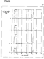
- FIG. 16 is a diagram showing an example of moving standard deviation MS calculated by the processing unit in the processing apparatus according to the embodiment of the present disclosure.
- FIG. 16 shows a graph G4 in which the horizontal axis represents time (seconds) and the vertical axis represents moving standard deviation MS (Nm).
- a solid line indicates moving standard deviation MS1
- a broken line indicates moving standard deviation MS2
- a one dot chain line indicates moving standard deviation MS3
- a two dot chain line indicates moving standard deviation MS4.
- processing unit 130 detects the abnormality of cutting blade 14 based on the calculated moving standard deviation MS. More specifically, processing unit 130 monitors a change of each moving standard deviation MS, and determines that the increase in moving standard deviation MS is not caused by the abnormality of cutting blade 14 when all moving standard deviations MS are increased, while determines that the abnormality occurs in cutting blade 14 when detecting that some of moving standard deviations MS are increased.
- processing unit 130 determines that moving standard deviations MS simultaneously increase at the time ts which is the start time of the cutting process and the time te which is the end time of the cutting process, but determines that the increase in moving standard deviations MS are not caused by the abnormality of cutting blade 14.
- processing unit 130 detects that only moving standard deviations MS2 and MS3 have increased at a time t1 and a time t2
- processing unit 130 determines that abnormality has occurred in at least one of cutting blades 14B and 14C corresponding to unit regions A2 and A3, respectively, based on the correspondence information R in storage unit 140.
- processing unit 130 determines that cutting blade 14B that first comes into contact with the cutting object among cutting blades 14B and 14C corresponding to moving standard deviations MS2 and MS3 that successively come into contact with the cutting object is broken.
- the difference in the amount of change in moving standard deviation MS for each unit region A is larger than the difference in the amount of change in moving standard deviation ms for each unit region A. Therefore, by performing detection processing using moving standard deviation MS, it is possible to more easily detect the abnormality in cutting blade 14.
- K is a specific cutting force.
- Ap is a cutting amount in the direction of rotation axis 17 of cutting blade 14.
- Hn is a positional deviation in the direction of rotation axis 17 of cutting blade 14 that cuts into the cutting object the n-th.
- Fz is a feed rate per blade.
- Rn is a positional deviation in the radial direction of shank portion 11 of cutting blade 14 that cuts into the cutting object the n-th. Note than the cutting amount ap and the feed rate fz are set values set as cutting conditions.
- the term ap ⁇ rn has a value about three times a value of the term hn ⁇ fz
- the term ap ⁇ fz has a value about ten times a value of the term ap ⁇ rn.
- Ap and fz are values determined in accordance with set values in the machining conditions.
- hn and ⁇ rn are values generated due to a deviation of the attachment position when cutting blade 14 is attached to blade fixing portion 13 or a lack of cutting blade 14, it is possible to more accurately detect a lack of cutting blade 14 by focusing on hn and ⁇ rn.
- FIGS. 17 and 18 are frequency distributions showing calculation results of the cutting force of the cutting blade in the cutting tool according to the embodiment of the present disclosure. More specifically, FIGS. 17 and 18 show the frequency distribution obtained by numerically calculating the variation of the cutting force of cutting blade 14 in consideration of the deviation of the attachment position when cutting blade 14 is attached to blade fixing portion 13.
- the horizontal axis represents the ratio P [%] of the cutting force F to the product apfz of the cutting amount ap and the feed rate fz
- the vertical axis represents the frequency.
- FIG. 17 shows the ratio Ps which is the ratio P of the cutting force F of one cutting blade 14 among four cutting blades 14 attached to cutting tool 101
- FIG. 18 shows the ratio Pm which is the ratio P of an average value Fmean of the cutting forces F of four cutting blades 14 attached to cutting tool 101.
- difference DF is obtained by eliminating the term ap ⁇ fz from equation (3), and is represented only by terms including hn or ⁇ rn. Therefore, by focusing on difference DF between the cutting force Fn and the average value Fmean, accurate detection processing can be performed.
- moving standard deviation ms is a value corresponding to the cutting force F received by each cutting blade 14 in cutting tool 101.
- average value Ams of moving standard deviations ms1 to ms4 is a value corresponding to the average value Fmean of the cutting forces F received by all cutting blades 14. Therefore, by calculating difference Dms between moving standard deviation ms and average value Ams and focusing on moving standard deviation MS of difference Dms, it is possible to more accurately detect a change in two-dimensional data D based on the occurrence of the abnormality of cutting blade 14, that is, a change in the cutting force F, and to perform more accurate detection processing.
- Processing unit 130 is not limited to the configuration in which the abnormality of cutting blade 14 is detected based on moving standard deviation MS, and may be configured to detect the abnormality of cutting blade 14 using other methods such as an autoregressive model (AR model), an autoregressive moving average model (ARMA model), and Bayesian Online Changepoint Detection.
- AR model autoregressive model
- ARMA model autoregressive moving average model
- Bayesian Online Changepoint Detection Bayesian Online Changepoint Detection.
- processing unit 130 After performing the classification processing, processing unit 130 performs a display processing, which is a processing for displaying the classification result on display unit 150.
- FIG. 19 is a diagram showing an example of a display screen displayed on a display unit in a processing apparatus according to an embodiment of the present disclosure.
- processing unit 130 performs a process of displaying a display screen DS including two-dimensional coordinate C in which the plot of two-dimensional data D and unit region A are illustrated as the classification result on display unit 150.
- processing unit 130 performs a process of displaying two-dimensional data D in a manner different for each unit region A. More specifically, for example, processing unit 130 performs a process of displaying display screen DS including two-dimensional coordinate C in which plots of different colors are illustrated for each unit region A on display unit 150. Alternatively, processing unit 130 performs a process of displaying display screen DS including two-dimensional coordinate C in which plots having different shapes are illustrated for each unit region A on display unit 150. Alternatively, processing unit 130 performs a process of displaying a display screen DS including two-dimensional coordinate C in which plots of different colors and shapes are illustrated for each unit region A on display unit 150.
- processing unit 130 performs a process of displaying a temporal change of two-dimensional data D for each unit region A. More specifically, processing unit 130 performs a process of displaying display screen DS including the graph G1 indicating the temporal change of moving standard deviation ms and the graph G4 indicating the temporal change of moving standard deviation MS together with two-dimensional coordinate C on display unit 150.
- Processing unit 130 generates quadratic functions F1 and F2 using the plurality of two-dimensional data D received from generation unit 120.
- FIG. 20 is a diagram showing a method of determining a unit region by a processing unit in a processing apparatus according to an embodiment of the present disclosure.
- processing unit 130 first converts each two-dimensional data D into a polar coordinate system. Then, processing unit 130 classifies each two-dimensional data D into four provisional unit regions Ap1, Ap2, Ap3, and Ap4 in two-dimensional coordinate C by provisional boundary lines Lp1( ⁇ ) and Lp2( ⁇ ) which are two straight lines passing through the origin in two-dimensional coordinate C and orthogonal to each other.
- processing unit 130 calculates an angle sum Asum1( ⁇ ) which is a sum of angles formed by a bisector Lb1 of provisional boundary lines Lp1( ⁇ ) and Lp2( ⁇ ) defining provisional unit region Ap1 and each two-dimensional data D classified into provisional unit region Ap1.
- processing unit 130 calculates an angle sum Asum2( ⁇ ) which is a sum of angles formed by a bisector Lb2 of provisional boundary lines Lp1( ⁇ ) and Lp2( ⁇ ) defining provisional unit region Ap2 and each two-dimensional data D classified into provisional unit region Ap2.
- processing unit 130 calculates an angle sum Asum3( ⁇ ) which is a sum of angles formed by bisector Lb1 of provisional boundary lines Lp1( ⁇ ) and Lp2( ⁇ ) defining provisional unit region Ap3 and each two-dimensional data D classified into provisional unit region Ap3.
- processing unit 130 calculates an angle sum Asum4( ⁇ ) which is a sum of angles formed by bisector Lb2 of provisional boundary lines Lp1( ⁇ ) and Lp2( ⁇ ) defining provisional unit region Ap4 and each two-dimensional data D classified into provisional unit region Ap4.
- Processing unit 130 calculates a sum of angle sums Asum1( ⁇ ), Asum2( ⁇ ), Asum3( ⁇ ), and Asum4( ⁇ ) as an evaluation value V( ⁇ ).
- processing unit 130 shifts provisional boundary lines Lp1( ⁇ ) and Lp2( ⁇ ) by a small angle, for example, 1° around the origin, and calculates an evaluation value V( ⁇ +1) in the above-described procedure using provisional boundary lines Lp1( ⁇ +1) and Lp2( ⁇ +1) obtained by shifting provisional boundary lines Lp1( ⁇ ) and Lp2( ⁇ ) by 1°.
- processing unit 130 repeatedly calculates an evaluated value V( ⁇ +n) while shifting provisional boundary lines Lp1( ⁇ ) and Lp2( ⁇ ) by 1° until provisional boundary lines Lp1( ⁇ ) and Lp2( ⁇ ) are rotated by 360° around the origin.
- n is an integer of 1 or more and 360 or less.
- Processing unit 130 determines provisional boundary lines Lp1( ⁇ +n) and Lp2( ⁇ +n) as boundary lines L1 and L2 when evaluation value V( ⁇ +n) is the minimum, generates quadratic function F1 indicating boundary line L1 and quadratic function F2 indicating boundary line L2, and stores generated quadratic functions F1 and F2 in storage unit 140.
- Processing unit 130 may generate quadratic functions F1 and F2 before the start of the cutting process each time the cutting process is performed, or may generate quadratic functions F1 and F2 each time the positional relationship between cutting blade 14 and sensor 20 is changed due to replacements of cutting blade 14 or sensor 20.
- Each apparatus in the cutting system according to the embodiment of the present disclosure is provided with a computer including a memory, and an arithmetic processing unit such as a CPU in the computer reads a program including a part or all of each step of the following flowcharts and sequences from the memory and executes the program.
- the programs of the plurality of apparatuses are distributed in a state of being stored in recording media such as an HDD (Hard Disk Drive), a CD-ROM (Compact Disc Read Only Memory), a DVD-ROM (Digital Versatile Disk Read Only Memory), and a semiconductor memory.
- the programs of the plurality of apparatuses can be installed from the outside.
- the programs of the plurality of apparatuses can be installed from the recording medium described above.
- the programs of the plurality of apparatuses can be downloaded and installed from a predetermined server or the like via a network typified by an electric communication line, a wireless communication line, a wired communication line, and the Internet. Further, for example, the programs of the plurality of apparatuses can be downloaded and installed from a predetermined server or the like by data broadcasting or the like.
- FIG. 21 is a flowchart defining an example of an operation procedure when the processing apparatus in the cutting system according to the embodiment of the present disclosure determines a state of a cutting blade.
- processing apparatus 201 waits for a wireless signal from wireless communication apparatus 23 in cutting tool 101 (NO in step S102), and upon receiving the wireless signal (YES in step S102), acquires the sensor measurement values sx, sy, sr and the identification information from the received wireless signal (step S 104).
- processing apparatus 201 generates two-dimensional data D indicating moments Mx and My based on the acquired sensor measurement values sx, sy, sr and the conversion matrix in storage unit 140 (step S106).
- processing apparatus 201 classifies generated two-dimensional data D into any one of unit regions A1, A2, A3, and A4 (step S108).
- processing apparatus 201 calculates moving standard deviation MS based on two-dimensional data D for each unit region A (step S110).
- processing apparatus 201 determines that abnormality has occurred in cutting blade 14 (step S114).
- processing apparatus 201 performs a process of displaying display screen DS including two-dimensional coordinate C in which the plot of two-dimensional data D and unit regions A are illustrated, the graph G1 indicating the temporal change of moving standard deviation ms, and the graph G3 indicating the temporal change of moving standard deviation MS on display unit 150 (Step S116).
- processing apparatus 201 waits for a new wireless signal from wireless communication apparatus 23 in cutting tool 101 (NO in step S102).
- processing apparatus 201 determines that abnormality has not occurred in cutting blade 14 (step S118).
- processing apparatus 201 performs a process of displaying display screen DS including two-dimensional coordinate C in which the plot of two-dimensional data D and unit regions A are illustrated, the graph G1 indicating the temporal change of moving standard deviation ms, and the graph G4 indicating the temporal change of moving standard deviation MS on display unit 150 (Step S116).
- processing apparatus 201 waits for a new wireless signal from wireless communication apparatus 23 in cutting tool 101 (NO in step S102).
- step 116 and steps S112, S114, S118 is not limited to the above, and the order may be changed. In addition, any one of step S116 and steps S112, S114, S118 may not be performed.
- FIG. 22 is a diagram showing an example of a sequence of detection processing and display processing in the cutting system according to the embodiment of the present disclosure.
- cutting tool 101 starts a cutting process using two or more cutting blades (step S202).
- strain sensors 20 provided in cutting tool 101 start measuring strain ⁇ of shank portion 11 (Step S204).
- cutting tool 101 includes sensor measurement values sx, sy, and sr based on the analog signals from strain sensors 20 in a wireless signal and transmits the wireless signal to processing apparatus 201 (step S206).
- processing apparatus 201 acquires the sensor measurement values sx, sy, sr from the wireless signal received from cutting tool 101, and generates two-dimensional data D indicating moments Mx and My based on the acquired sensor measurement values sx, sy, sr and the conversion matrix in storage unit 140 (step S208).
- processing apparatus 201 performs classification processing (step S210).
- processing apparatus 201 performs detection processing (step S212).
- processing apparatus 201 performs display processing (step S214).
- cutting tool 101 includes new sensor measurement values sx, sy, and sr based on the analog signals from strain sensors 20 in a wireless signal and transmits the wireless signal to processing apparatus 201 (step S216).
- cutting tool 101 is an end mill including four blade fixing portions 13, it is not limited thereto.
- Cutting tool 101 may be configured to include two, three, five or more blade fixing portions 13. Further, cutting tool 101 may be a tool other than the end mill, such as a face milling cutter.
- cutting system 301 has a configuration in which the number of strain sensors 20 is irrelevant to the number of cutting blades 14 in cutting tool 101, it is not limited thereto.
- Cutting system 301 may include a number of strain sensors 20 that has some correlation with the number of cutting blades 14.
- cutting system 301 is configured to include a smaller number of strain sensors 20 than the number of cutting blades 14 in cutting tool 101, but it is not limited thereto.
- Cutting system 301 may be configured to include a number of strain sensors 20 equal to or greater than the number of cutting blades 14 in cutting tool 101.
- strain sensors 20 are provided on shank portion 11 of cutting tool 101, but it is not limited thereto. Strain sensor 20 may be provided in blade attaching portion 12 of cutting tool 101. Further, strain sensor 20 may be provided on tool holder 210, for example.
- strain sensor 20 is configured to measure strain ⁇ of shank portion 11 in the direction parallel to rotation axis 17, but it is not limited thereto. Strain sensor 20 may be configured to measure the shear strain of shank portion 11.
- generation unit 120 generates two-dimensional data D indicating a load Fx in the X direction and a load Fy in the Y direction received by cutting tool 101 within cutting resistance acting surface 18, based on the sensor measurement value indicating the shear strain measured by strain sensor 20.
- cutting system 301 may be configured to include other sensors such as an acceleration sensor, a velocity sensor, and a displacement sensor instead of strain sensor 20 or in addition to strain sensor 20 as the plurality of sensors.
- generation unit 120 generates two-dimensional data D indicating the acceleration in the X-direction and the acceleration in the Y-direction of cutting tool 101 in cutting resistance acting surface 18, two-dimensional data D indicating the velocity in the X-direction and the velocity in the Y-direction of cutting tool 101 in cutting resistance acting surface 18, or two-dimensional data D indicating the displacement in the X-direction and the displacement in the Y-direction of cutting tool 101 in cutting resistance acting surface 18 based on the measurement results by the sensor.
- two-dimensional data D generated by generation unit 120 based on the measurement results and related to a cutting force F applied to one cutting blade 14 and two-dimensional data D related to a cutting force F applied to another cutting blade 14 point-symmetric to said cutting blade 14 with respect to rotation axis 17 appear at substantially the same position in two-dimensional coordinate C, and it may be difficult to classify two-dimensional data D for each cutting blade 14.
- cutting tool 101 in which cutting blades 14 are not provided at point symmetrical positions related to rotation axis 17.
- cutting tool 101 including three blade fixing portions 13 at equal intervals around rotation axis 17 in blade attaching portion 12, or cutting tool 101 including five blade fixing portions 13 at equal intervals around rotation axis 17 in blade attaching portion 12.
- processing unit 130 is configured to classify the plurality of two-dimensional data D received from generation unit 120 into any one of the same number of unit regions A as the number of cutting blades 14 in the plane perpendicular to rotation axis 17, where the number is four, but it is not limited thereto.
- Processing unit 130 may be configured to classify the plurality of two-dimensional data D into any one of unit regions A whose number is larger than the number of cutting blades 14 in the plane perpendicular to rotation axis 17.
- processing unit 130 performs classification processing that is a process of classifying the plurality of two-dimensional data D into any one of twelve unit regions A in the plane perpendicular to rotation axis 17.
- unit region A is each region when 360 degrees is divided every 30 degrees. That is, unit region A is each region when the plane perpendicular to rotation axis 17 is equally divided into twelve regions around rotation axis 17 by six straight lines which are straight lines on the plane and pass through rotation axis 17.
- processing unit 130 is configured to detect the abnormality of cutting blade 14 based on the temporal change of the index value based on two-dimensional data D, but it is not limited thereto. Processing unit 130 may be configured to detect the abnormality of cutting blade 14 based on an absolute value of the index value based on two-dimensional data D.
- processing unit 130 is configured to calculate moving standard deviation ms in each unit region A, but it is not limited thereto. Processing unit 130 may be configured to calculate a moving maximum value in each unit region A as the index value for each unit region A, or may be configured to calculate a moving average ma in each unit region A.
- processing unit 130 calculates moving average ma of distance R from the origin of two-dimensional data D in each unit region A. To be more specific, processing unit 130 calculates a moving average ma1 of distances R1 of two-dimensional data D1, a moving average ma2 of distances R2 of two-dimensional data D2, a moving average ma3 of distances R3 of two-dimensional data D3, and a moving average ma4 of distances R4 of two-dimensional data D4.
- FIG. 23 is a diagram showing an example of moving average ma calculated by the processing unit in the processing apparatus according to Modification 7 of the embodiment of the present disclosure.
- FIG. 23 shows a graph G5 in which the horizontal axis represents time [seconds] and the vertical axis represents moving average ma [Nm].
- a solid line indicates moving average ma1
- a broken line indicates moving average ma2
- a one dot chain line indicates moving average ma3
- a two dot chain line indicates moving average ma4.
- processing unit 130 performs detection processing based on a temporal change of calculated moving average ma.
- processing unit 130 calculates a moving standard deviation MA of a difference Dma between moving average ma for each unit region A and an average value Ama of moving average ma of each unit region A.
- processing unit 130 calculates average value Ama of moving averages ma1 to ms4. Then, processing unit 130 calculates moving standard deviation MA of difference Dma between each moving average ma and average value Ama of moving averages ma. To be more specific, processing unit 130 calculates a moving standard deviation MA1 of a difference Dma1 between moving average ma1 and average value Ama, a moving standard deviation MA2 of a difference Dma2 between moving average ma2 and average value Ama, a moving standard deviation MA3 of a difference Dma3 between moving average ma3 and average value Ama, and a moving standard deviation MA4 of a difference DMa4 between moving average ma4 and average value Ama.
- FIG. 24 is a diagram showing an example of average value Ama calculated by the processing unit in the processing apparatus according to Modification 7 of the embodiment of the present disclosure.
- FIG. 24 shows a graph G6 in which the horizontal axis represents time (seconds) and the vertical axis represents average value Ama (Nm).
- FIG. 25 is a diagram showing an example of difference Dma calculated by the processing unit in the processing apparatus according to Modification 7 of the embodiment of the present disclosure.
- FIG. 25 shows a graph G7 in which the horizontal axis represents time (seconds) and the vertical axis represents difference Dma (Nm).
- a solid line indicates difference Dma1
- a broken line indicates difference Dma2
- a one dot chain line indicates difference Dma3
- a two dot chain line indicates difference Dma4.
- FIG. 26 is a diagram showing an example of the moving standard deviation MA calculated by the processing unit in the processing apparatus according to Modification 7 of the embodiment of the present disclosure.
- FIG. 26 shows a graph G8 in which the horizontal axis represents time (seconds) and the vertical axis represents moving standard deviation MA (Nm).
- a solid line indicates moving standard deviation MA1
- a broken line indicates moving standard deviation MA2
- a one dot chain line indicates moving standard deviation MA3
- a two dot chain line indicates moving standard deviation MA4.
- processing unit 130 detects the abnormality of cutting blade 14 based on calculated moving standard deviation MA. More specifically, processing unit 130 monitors a change of each moving standard deviation MA, and when all moving standard deviations MA are increased, determines that the increase is not caused by the abnormality of cutting blade 14, while determines that the abnormality occurs in cutting blade 14 when detecting that some of moving standard deviations MA are increased.
- processing unit 130 is configured to calculate moving standard deviation ms of distance R from the origin of two-dimensional data D in each unit region A after classifying two-dimensional data D received from generation unit 120, but it is not limited thereto.
- Processing unit 130 may be configured to calculate moving standard deviation ms using only distance R equal to or greater than a predetermined threshold value in each unit region A. That is, processing unit 130 may be configured to truncate two-dimensional data D.
- the two-dimensional data in which distance R is less than the predetermined value may be data before or after cutting blade 14 comes into contact with the cutting object, and thus more accurate detection processing can be performed by performing truncation of two-dimensional data D.
- cutting system 301 is configured to include processing apparatus 201 separately from cutting tool 101, it is not limited thereto.
- Processing apparatus 201 may be provided in cutting tool 101, or may be provided in a machine tool.
- processing apparatus 201 is configured to perform detection processing and display processing, but it is not limited thereto.
- Processing apparatus 201 may be configured not to perform any one of detection processing and display processing.
- Patent Literature 1 describes that a strain sensor is attached to each cutting blade of a cutting tool, and abnormality of the corresponding cutting blade is detected based on a measurement value of each strain sensor.
- the measurement value of each strain sensor becomes a value affected by a cutting force applied to a cutting blade other than the corresponding cutting blade, that is, a value affected by cutting forces applied to the plurality of cutting blades coming into contact with the cutting object.
- a measurement value related to a cutting force applied to only one blade portion cannot be acquired from a corresponding strain sensor. Therefore, the abnormality of the cutting blade may not be accurately detected.
- the technique described in Patent Literature 1 since the number of sensors corresponding to the number of cutting blades is required, the cost increases as the number of cutting blades increases.
- Patent Literature 10 it is described that a sensor for measuring the driving force of the main shaft of the machine tool is used.
- a sensor for measuring the driving force of the main shaft of the machine tool is used.
- the process of classifying two-dimensional data D generated based on the measurement results by the sensor into unit region A is not performed, for example, the cutting force applied to the cutting blade cannot be analyzed for each cutting blade, and the abnormality of the cutting blade cannot be accurately detected in some cases.
- cutting tool 101 performs the cutting process using two or more cutting blades 14.
- Strain sensor 20 measures a physical quantity indicating a state related to the load of cutting tool 101 at a time of the cutting process.
- Processing apparatus 201 generates, based on the measurement results obtained by strain sensor 20 at a plurality of measurement timings, two-dimensional data D for each measurement timing, where two-dimensional data D relate to the loads in two directions in a plane perpendicular to the rotation axis of cutting tool 101, classifies pieces of generated two-dimensional data D into any of a plurality of unit regions A, a number of which is greater than or equal to a number of cutting blades 14 on the plane, and detects, based on two-dimensional data D for each of unit regions A, the abnormality of cutting blade 14.
- wireless communication unit 110 acquires measurement results of strain sensor 20, that is, measurement results of a physical quantity indicating a state related to the load at a time of the cutting process in cutting tool 101 for milling performing the cutting process using two or more cutting blades.
- Generation unit 120 generates, based on the measurement results obtained by each of strain sensor 20 at a plurality of measurement timings acquired by wireless communication unit 110, two-dimensional data D for each of the measurement timings, where two-dimensional data D relate to the loads in two directions in a plane perpendicular to rotation axis 17 of cutting tool 101.
- Processing unit 130 classifies pieces of two-dimensional data D generated by generation unit 120 into any of a plurality of unit regions A, a number of which is greater than or equal to a number of cutting blades 14 on the plane, and detects, based on two-dimensional data D for each of the unit regions A, the abnormality of cutting blade 14.
- the processing method according to the embodiment of the present disclosure is a processing method in processing apparatus 201.
- processing apparatus 201 acquires the measurement results of strain sensors 20, that is, the measurement results of the physical quantity indicating the state related to the load at a time of cutting process in cutting tool 101 for milling that performs the cutting process using two or more cutting blades 14.
- processing apparatus 201 generates, based on the acquired measurement results obtained by each of strain sensors 20 at a plurality of measurement timings, two-dimensional data D for each of the measurement timings, where two-dimensional data D relate to the loads in two directions on a plane perpendicular to rotation axis 17 of cutting tool 101.
- processing apparatus 201 classifies pieces of generated two-dimensional data D into any of a plurality of unit regions A, a number of which is greater than or equal to a number of cutting blades 14 on the plane, and detects, based on two-dimensional data D for each of unit regions A, the abnormality of cutting blades 14.
- the configuration and the method of classifying the pieces of two-dimensional data D generated based on the measurement results of strain sensors 20 into any one of the plurality of unit regions A in the plane perpendicular to rotation axis 17 and detecting the abnormality of cutting blade 14 based on two-dimensional data D of each unit region A the change in two-dimensional data D in only some of the unit regions caused by the occurrence of the abnormality of the cutting blade can be detected separately from the change in two-dimensional data D in all the unit regions caused by the change in the cutting condition.
- cutting tool 101 performs the cutting process using two or more cutting blades 14.
- Strain sensor 20 measures a physical quantity indicating the state related to the load of cutting tool 101 at a time of the cutting process.
- Processing apparatus 201 performs the process of generating, based on measurement results obtained by each of strain sensor 20 at a plurality of measurement timings, two-dimensional data D for each of the measurement timings, where two-dimensional data D are regarding the loads in two directions in a plane perpendicular to the rotation axis of cutting tool 101, classifying pieces of generated two-dimensional data D into any of a plurality of unit regions A, a number of which is greater than or equal to a number of cutting blades 14 on the plane, and displaying a classification result.
- wireless communication unit 110 acquires measurement results of strain sensors 20, that is, the measurement results of a physical quantity indicating the state related to the load at a time of the cutting process in cutting tool 101 for milling performing the cutting process using two or more cutting blades.
- Generation unit 120 generates based on the measurement results obtained by each of strain sensor 20 at a plurality of measurement timings acquired by wireless communication unit 110, two-dimensional data D for each of the measurement timings, where two-dimensional data D are regarding the loads in two directions on a plane perpendicular to rotation axis 17 of cutting tool 101.
- Processing unit 130 performs a process of classifying pieces of two-dimensional data D generated by generation unit 120 into any of a plurality of unit regions A, a number of which is greater than or equal to a number of cutting blades 14 on the plane, and displaying a classification result.
- the processing method according to the embodiment of the present disclosure is a processing method in processing apparatus 201.
- processing apparatus 201 acquires measurement results of strain sensors 20, that is, the measurement results of a physical quantity indicating the state related to the load at a time of the cutting process in cutting tool 101 for milling performing the cutting process using two or more cutting blades 14.
- processing apparatus 201 generates, based on the acquired measurement results obtained by each of strain sensors 20 at a plurality of measurement timings, two-dimensional data D for each of the measurement timings, where two-dimensional data D are regarding the loads in two directions on a plane perpendicular to rotation axis 17 of cutting tool 101.
- processing apparatus 201 performs a process of classifying pieces of generated two-dimensional data D into any of a plurality of unit regions A, a number of which is greater than or equal to a number of cutting blades 14 on the plane and displaying a classification result.
- each two-dimensional data D generated based on the measurement results of strain sensor 20 is classified into any one of the plurality of unit regions A in the plane perpendicular to rotation axis 17, and the classification result is displayed, for example, the state of each cutting blade can be displayed as two-dimensional data for each unit region A. Therefore, the state of each cutting blade 14 can be recognized by the user.
- a cutting system including:
- a display system including:
Landscapes
- Engineering & Computer Science (AREA)
- Mechanical Engineering (AREA)
- Human Computer Interaction (AREA)
- Manufacturing & Machinery (AREA)
- Physics & Mathematics (AREA)
- General Physics & Mathematics (AREA)
- Automation & Control Theory (AREA)
- Numerical Control (AREA)
- Machine Tool Sensing Apparatuses (AREA)
- Milling Processes (AREA)
- Instructional Devices (AREA)
- Position Fixing By Use Of Radio Waves (AREA)
Abstract
Description
- The present disclosure relates to a cutting system, a display system, a processing apparatus, a processing method, and a processing program.
- Patent Literature 1 (
Japanese Unexamined Patent Application Publication No. 2015-77658 -
- [Patent Literature 1]
Japanese Unexamined Patent Application Publication No. 2015-77658 - [Patent Literature 2]
Japanese Unexamined Patent Application Publication No. 2013-132734 - [Patent Literature 3]
Japanese Unexamined Patent Application Publication No. 2018-43317 - [Patent Literature 4]
Japanese Unexamined Patent Application Publication No. 2018-24086 - [Patent Literature 5]
Japanese Unexamined Patent Application Publication No. 2006-71485 - [Patent Literature 6]
Japanese Unexamined Patent Application Publication No. 11-118625 - [Patent Literature 7]
Japanese Unexamined Patent Application Publication No. 2016-40071 - [Patent Literature 8]
U.S. Unexamined Patent Application Publication No. 2015/0261207 - [Patent Literature 9]
European Unexamined Patent Application Publication No. 3486737 - [Patent Literature 10]
Japanese Unexamined Patent Application Publication No. 2018-24086 -
- (1) A cutting system according to the present disclosure includes a cutting tool for milling, a plurality of sensors, and a processing unit, wherein the cutting tool performs a cutting process using two or more cutting blades, the plurality of sensors measure a physical quantity indicating a state regarding a load of the cutting tool at a time of the cutting process, and the processing unit generates, based on measurement results obtained by each of the sensors at a plurality of measurement timings, two-dimensional data for each of the measurement timings, the two-dimensional data regarding the load in two directions on a plane perpendicular to a rotation axis of the cutting tool, classifies pieces of the generated two-dimensional data into any of a plurality of unit regions, a number of which is greater than or equal to a number of the cutting blades on the plane, and detects, based on the two-dimensional data for each of the unit regions, an abnormality of the cutting blades.
- (8) A processing apparatus according to the present disclosure includes an acquisition unit configured to acquire measurement results of a physical quantity indicating a state regarding a load of a cutting tool for milling, the cutting tool being configured to perform a cutting process using two or more cutting blades, at a time of the cutting process, the measurement results being obtained by a plurality of sensors, a generation unit configured to generate, based on the measurement results obtained by each of the sensors at a plurality of measurement timings, the measurement results being acquired by the acquisition unit, two-dimensional data for each of the measurement timings, the two-dimensional data regarding the load in two directions on a plane perpendicular to a rotation axis of the cutting tool, and a detection unit configured to classify pieces of the two-dimensional data generated by the generation unit into any of a plurality of unit regions, a number of which is greater than or equal to a number of the cutting blades on the plane, and detect, based on the two-dimensional data for each of the unit regions, an abnormality of the cutting blades.
- (9) A processing method according to the present disclosure is a processing method in a processing apparatus, the processing method includes acquiring measurement results of a physical quantity indicating a state regarding a load of a cutting tool for milling, the cutting tool being configured to perform a cutting process using two or more cutting blades, at a time of the cutting process, the measurement results being obtained by a plurality of sensors, generating, based on the acquired measurement results obtained by each of the sensors at a plurality of measurement timings, two-dimensional data for each of the measurement timings, the two-dimensional data regarding the load in two directions on a plane perpendicular to a rotation axis of the cutting tool, and classifying pieces of the generated two-dimensional data into any of a plurality of unit regions, a number of which is greater than or equal to a number of the cutting blades on the plane, and detecting, based on the two-dimensional data for each of the unit regions, an abnormality of the cutting blades.
- (10) A processing program according to the present disclosure is a processing program to be used in a processing apparatus, the processing program being for causing a computer to function as, an acquisition unit configured to acquire measurement results of a physical quantity indicating a state regarding a load of a cutting tool for milling, the cutting tool being configured to perform a cutting process using two or more cutting blades, at a time of the cutting process, the measurement results being obtained by a plurality of sensors, a generation unit configured to generate, based on the measurement results obtained by each of the sensors at a plurality of measurement timings, the measurement results being acquired by the acquisition unit, two-dimensional data for each of the measurement timings, the two-dimensional data regarding the load in two directions on a plane perpendicular to a rotation axis of the cutting tool, and a detection unit configured to classify pieces of the two-dimensional data generated by the generation unit into any of a plurality of unit regions, a number of which is greater than or equal to a number of the cutting blades on the plane, and detect, based on the two-dimensional data for each of the unit regions, an abnormality of the cutting blades.
- (11) A display system according to the present disclosure includes a cutting tool for milling, a plurality of sensors, and a processing apparatus, wherein the cutting tool performs a cutting process using two or more cutting blades, the plurality of sensors measure a physical quantity indicating a state regarding a load of the cutting tool at a time of the cutting process, and the processing apparatus performs a process of generating, based on measurement results obtained by each of the sensors at a plurality of measurement timings, two-dimensional data for each of the measurement timings, the two-dimensional data regarding the load in two directions on a plane perpendicular to a rotation axis of the cutting tool, classifying pieces of the generated two-dimensional data into any of a plurality of unit regions, a number of which is greater than or equal to a number of the cutting blades on the plane, and displaying a classification result.
- (14) A processing apparatus according to the present disclosure includes an acquisition unit configured to acquire measurement results of a physical quantity indicating a state regarding a load of a cutting tool for milling, the cutting tool being configured to perform a cutting process using two or more cutting blades, at a time of the cutting process, the measurement results being obtained by a plurality of sensors, a generation unit configured to generate, based on the measurement results obtained by each of the sensors at a plurality of measurement timings, the measurement results being acquired by the acquisition unit, two-dimensional data for each of the measurement timings, the two-dimensional data regarding the load in two directions on a plane perpendicular to a rotation axis of the cutting tool, and a display processing unit configured to perform a process of classifying pieces of the two-dimensional data generated by the generation unit into any of a plurality of unit regions, a number of which is greater than or equal to a number of the cutting blades on the plane, and displaying a classification result.
- (15) A processing method according to the present disclosure is a processing method in a processing apparatus, the processing method includes acquiring measurement results of a physical quantity indicating a state regarding a load of a cutting tool for milling, the cutting tool being configured to perform a cutting process using two or more cutting blades, at a time of the cutting process, the measurement results being obtained by a plurality of sensors, generating, based on the acquired measurement results obtained by each of the sensors at a plurality of measurement timings, two-dimensional data for each of the measurement timings, the two-dimensional data regarding the load in two directions on a plane perpendicular to a rotation axis of the cutting tool, and performing a process of classifying pieces of the generated two-dimensional data into any of a plurality of unit regions, a number of which is greater than or equal to a number of the cutting blades on the plane, and displaying a classification result.
- (16) A processing program according to the present disclosure is a processing program to be used in a processing apparatus, the processing program being for causing a computer to function as, an acquisition unit configured to acquire measurement results of a physical quantity indicating a state regarding a load of a cutting tool for milling, the cutting tool being configured to perform a cutting process using two or more cutting blades, at a time of the cutting process, the measurement results being obtained by a plurality of sensors, a generation unit configured to generate, based on the measurement results obtained by each of the sensors at a plurality of measurement timings, the measurement results being acquired by the acquisition unit, two-dimensional data for each of the measurement timings, the two-dimensional data regarding the load in two directions on a plane perpendicular to a rotation axis of the cutting tool, and a display processing unit configured to perform a process of classifying pieces of the two-dimensional data generated by the generation unit into any of a plurality of unit regions, a number of which is greater than or equal to a number of the cutting blades on the plane, and displaying a classification result.
- An aspect of the present disclosure can be realized not only as a cutting system including such a characteristic processing unit but also as a semiconductor integrated circuit that realizes a part or all of the cutting system. Further, one aspect of the present disclosure can be realized not only as a processing apparatus including such a characteristic processing unit but also as a semiconductor integrated circuit that realizes a part or all of the processing apparatus.
-
-
FIG. 1 is a diagram showing a configuration of a cutting system according to an embodiment of the present disclosure. -
FIG. 2 is a cross-sectional view showing a configuration of a cutting tool according to an embodiment of the present disclosure. -
FIG. 3 is an arrow view showing a configuration of a cutting tool according to an embodiment of the present disclosure. -
FIG. 4 is a diagram showing an example of measurement results of a strain sensor acquired by a wireless communication unit in a processing apparatus according to an embodiment of the present disclosure. -
FIG. 5 is a diagram showing an example of measurement results of a strain sensor acquired by a wireless communication unit in a processing apparatus according to an embodiment of the present disclosure. -
FIG. 6 is a diagram showing an example of measurement results of a strain sensor acquired by a wireless communication unit in a processing apparatus according to an embodiment of the present disclosure. -
FIG. 7 is a diagram showing an example of measurement results of a strain sensor acquired by a wireless communication unit in a processing apparatus according to an embodiment of the present disclosure. -
FIG. 8 is a diagram showing a configuration of a processing apparatus in a cutting system according to an embodiment of the present disclosure. -
FIG. 9 is a perspective view schematically showing a cutting tool according to an embodiment of the present disclosure. -
FIG. 10 is a diagram showing an example of two-dimensional data generated by a generation unit in a processing apparatus according to an embodiment of the present disclosure. -
FIG. 11 is a diagram showing another example of two-dimensional data generated by a generation unit in a processing apparatus according to an embodiment of the present disclosure. -
FIG. 12 is a diagram showing an example of a classification result of two-dimensional data by a processing unit in a processing apparatus according to an embodiment of the present disclosure. -
FIG. 13 is a diagram showing an example of a moving standard deviation ms calculated by a processing unit in a processing apparatus according to an embodiment of the present disclosure. -
FIG. 14 is a diagram showing an example of an average value Ams calculated by a processing unit in a processing apparatus according to an embodiment of the present disclosure. -
FIG. 15 is a diagram showing an example of a difference Dms calculated by a processing unit in a processing apparatus according to an embodiment of the present disclosure. -
FIG. 16 is a diagram showing an example of a moving standard deviation MS calculated by a processing unit in a processing apparatus according to an embodiment of the present disclosure. -
FIG. 17 is a frequency distribution showing a calculation result of a cutting force of a cutting blade in a cutting tool according to an embodiment of the present disclosure. -
FIG. 18 is a frequency distribution showing a calculation result of a cutting force of a cutting blade in a cutting tool according to an embodiment of the present disclosure. -
FIG. 19 is a diagram showing an example of a display screen displayed on a display unit in a processing apparatus according to an embodiment of the present disclosure. -
FIG. 20 is a diagram showing a method of determining a unit region by a processing unit in a processing apparatus according to an embodiment of the present disclosure. -
FIG. 21 is a flowchart defining an example of an operation procedure when a processing apparatus in a cutting system according to an embodiment of the present disclosure determines a state of a cutting blade. -
FIG. 22 is a diagram showing an example of a sequence of detection processing and display processing in a cutting system according to an embodiment of the present disclosure. -
FIG. 23 is a diagram showing an example of a moving average ma calculated by a processing unit in a processing apparatus according to Modification 7 of an embodiment of the present disclosure. -
FIG. 24 is a diagram showing an example of an average value Ama calculated by a processing unit in a processing apparatus according to Modification 7 of an embodiment of the present disclosure. -
FIG. 25 is a diagram showing an example of a difference Dma calculated by a processing unit in a processing apparatus according to Modification 7 of an embodiment of the present disclosure. -
FIG. 26 is a diagram showing an example of a moving standard deviation MA calculated by a processing unit in a processing apparatus according to Modification 7 of an embodiment of the present disclosure. - Conventionally, there has been proposed a technique in which a sensor is attached to a cutting tool and abnormality of a cutting blade in the cutting tool is detected based on measurement results by the sensor at a time of the cutting process.
- Beyond such a technique of
Patent Literature 1, a technique capable of realizing an excellent function related to a cutting blade in a cutting tool is desired. - The present disclosure has been made to solve the above-described problem, and an object thereof is to provide a cutting system, a display system, a processing apparatus, a processing method, and a processing program capable of realizing excellent functions related to a cutting blade in a cutting tool.
- According to the present disclosure, excellent functions of a cutting blade in a cutting tool can be realized.
- First, the contents of the embodiments of the present disclosure will be listed and explained.
- (1) A cutting system according to an embodiment of the present disclosure includes a cutting tool for milling, a plurality of sensors, and a processing unit. The cutting tool performs a cutting process using two or more cutting blades, the plurality of sensors measure a physical quantity indicating a state regarding a load of the cutting tool at a time of the cutting process, and the processing unit generates, based on measurement results obtained by each of the sensors at a plurality of measurement timings, two-dimensional data for each of the measurement timings, the two-dimensional data regarding the load in two directions on a plane perpendicular to a rotation axis of the cutting tool, classifies pieces of the generated two-dimensional data into any of a plurality of unit regions, a number of which is greater than or equal to a number of the cutting blades on the plane, and detects, based on the two-dimensional data for each of the unit regions, an abnormality of the cutting blades.
As describe above, each two-dimensional data generated based on the measurement results of the plurality of sensors is classified into any one of the plurality of unit regions in the plane perpendicular to rotation axis, and the abnormality of the cutting blade is detected based on the two dimensional data of each unit region. According to such a configuration, changes in two-dimensional data caused by the occurrence of cutting blade abnormality which occur only in some of unit regions can be detected distinctively from changes in two-dimensional data caused by changes in cutting conditions which occur in all unit regions. Thus, the abnormality of the cutting blade can be detected accurately. Therefore, excellent functions regarding the cutting blade in the cutting tool can be realized. - (2) Preferably, the processing unit classifies the pieces of the two-dimensional data into any of the unit regions, the number of which is equal to the number of the cutting blades.
With such a configuration, the cutting force applied to each cutting blade can be analyzed using the two-dimensional data in each unit region, so that the cutting blade corresponding to the unit region can be specified as the cutting blade in which abnormality has occurred when the two-dimensional data change only in some of unit regions. In addition, the two-dimensional data in each unit region can be used for various analyses other than detection of the abnormality of the cutting blade. - (3) Preferably, the processing unit sequentially generates and classifies the two-dimensional data, and detects, based on the number of the unit regions, for which a temporal change of the two-dimensional data is greater than or equal to a predetermined value, the abnormality of the cutting blades.
With such a configuration, it is possible to more reliably detect a slight change in the two-dimensional data in each unit region, and thus it is possible to more accurately detect the abnormality of the cutting blade. - (4) More preferably, the processing unit calculates an index value based on the two-dimensional data for the plurality of unit regions, calculates a standard deviation of a difference between the index value for each of the unit regions and an average value of the index values for the unit regions, and detects, based on the calculated standard deviation, the abnormality of the cutting blades.
As described above, by focusing on the standard deviation of the difference between the index value of each unit region and the average value of the index values of each of the unit regions, it is possible to more accurately detect a change in the two-dimensional data based on the occurrence of the abnormality of the cutting blade, and thus it is possible to more accurately detect the abnormality of the cutting blade. - (5) More preferably, the cutting system includes the sensors, a number of which is irrelevant to the number of the cutting blades in the cutting tool.
With such a configuration, it is possible to construct a cutting system using various cutting tools and a predetermined number of sensors regardless of the number of the cutting blades. - (6) More preferably, the cutting system includes the sensors, a number of which is less than the number of the cutting blades in the cutting tool.
With such a configuration, it is possible to reduce the number of necessary sensors compared to a system including the sensors, the number of which is equal to the number of the cutting blades, for example, and thus it is possible to construct a cutting system at lower cost. - (7) More preferably, the cutting tool includes a shank portion, and the plurality of sensors are provided in the shank portion.
With such a configuration, since the physical quantity indicating the state of each cutting blade can be measured more accurately, the abnormality of the cutting blade can be detected more accurately. - (8) A processing apparatus according to an embodiment of the present disclosure includes an acquisition unit configured to acquire measurement results of a physical quantity indicating a state regarding a load of a cutting tool for milling, the cutting tool being configured to perform a cutting process using two or more cutting blades, at a time of the cutting process, the measurement results being obtained by a plurality of sensors, a generation unit configured to generate, based on the measurement results obtained by each of the sensors at a plurality of measurement timings, the measurement results being acquired by the acquisition unit, two-dimensional data for each of the measurement timings, the two-dimensional data regarding the load in two directions on a plane perpendicular to a rotation axis of the cutting tool, and a detection unit configured to classify pieces of the two-dimensional data generated by the generation unit into any of a plurality of unit regions, a number of which is greater than or equal to a number of the cutting blades on the plane, and detect, based on the two-dimensional data for each of the unit regions, an abnormality of the cutting blades.
As describe above, each two-dimensional data generated based on the measurement results of the plurality of sensors is classified into any one of the plurality of unit regions in the plane perpendicular to rotation axis, and the abnormality of the cutting blade is detected based on the two dimensional data of each unit region. According to such a configuration, changes in two-dimensional data caused by the occurrence of cutting blade abnormality which occur only in some of unit regions can be detected distinctively from changes in two-dimensional data caused by changes in cutting conditions which occur in all unit regions. Thus, the abnormality of the cutting blade can be detected accurately. Therefore, excellent functions regarding the cutting blade in the cutting tool can be realized. - (9) A processing method according to an embodiment of the present disclosure is a processing method in a processing apparatus, the processing method includes acquiring measurement results of a physical quantity indicating a state regarding a load of a cutting tool for milling, the cutting tool being configured to perform a cutting process using two or more cutting blades, at a time of the cutting process, the measurement results being obtained by a plurality of sensors, generating, based on the acquired measurement results obtained by each of the sensors at a plurality of measurement timings, two-dimensional data for each of the measurement timings, the two-dimensional data regarding the load in two directions on a plane perpendicular to a rotation axis of the cutting tool, and classifying pieces of the generated two-dimensional data into any of a plurality of unit regions, a number of which is greater than or equal to a number of the cutting blades on the plane, and detecting, based on the two-dimensional data for each of the unit regions, an abnormality of the cutting blades.
As describe above, each two-dimensional data generated based on the measurement results of the plurality of sensors is classified into any one of the plurality of unit regions in the plane perpendicular to rotation axis, and the abnormality of the cutting blade is detected based on the two dimensional data of each unit region. According to such a method, changes in two-dimensional data caused by the occurrence of cutting blade abnormality which occur only in some of unit regions can be detected distinctively from changes in two-dimensional data caused by changes in cutting conditions which occur in all unit regions. Thus, the abnormality of the cutting blade can be detected accurately. Therefore, excellent functions regarding the cutting blade in the cutting tool can be realized. - (10) A processing program according to an embodiment of the present disclosure to be used in a processing apparatus, the processing program being for causing a computer to function as an acquisition unit configured to acquire measurement results of a physical quantity indicating a state regarding a load of a cutting tool for milling, the cutting tool being configured to perform a cutting process using two or more cutting blades, at a time of the cutting process, the measurement results being obtained by a plurality of sensors, a generation unit configured to generate, based on the measurement results obtained by each of the sensors at a plurality of measurement timings, the measurement results being acquired by the acquisition unit, two-dimensional data for each of the measurement timings, the two-dimensional data regarding the load in two directions on a plane perpendicular to a rotation axis of the cutting tool, and a detection unit configured to classify pieces of the two-dimensional data generated by the generation unit into any of a plurality of unit regions, a number of which is greater than or equal to a number of the cutting blades on the plane, and detect, based on the two-dimensional data for each of the unit regions, an abnormality of the cutting blades.
As describe above, each two-dimensional data generated based on the measurement results of the plurality of sensors is classified into any one of the plurality of unit regions in the plane perpendicular to rotation axis, and the abnormality of the cutting blade is detected based on the two dimensional data of each unit region. According to such a configuration, changes in two-dimensional data caused by the occurrence of cutting blade abnormality which occur only in some of unit regions can be detected distinctively from changes in two-dimensional data caused by changes in cutting conditions which occur in all unit regions. Thus, the abnormality of the cutting blade can be detected accurately. Therefore, excellent functions regarding the cutting blade in the cutting tool can be realized. - (11) A display system according to an embodiment of the present disclosure includes a cutting tool for milling, a plurality of sensors, and a processing apparatus. The cutting tool performs a cutting process using two or more cutting blades, the plurality of sensors measure a physical quantity indicating a state regarding a load of the cutting tool at a time of the cutting process, and the processing apparatus performs a process of generating, based on measurement results obtained by each of the sensors at a plurality of measurement timings, two-dimensional data for each of the measurement timings, the two-dimensional data regarding the load in two directions on a plane perpendicular to a rotation axis of the cutting tool, classifying pieces of the generated two-dimensional data into any of a plurality of unit regions, a number of which is greater than or equal to a number of the cutting blades on the plane, and displaying a classification result.
As described above, by the configuration of classifying each two-dimensional data generated based on the measurement results of the plurality of sensors into any one of the plurality of unit regions in the plane perpendicular to rotation axis and displaying the classification result, for example, since the state of each cutting blade can be displayed as two-dimensional data for each unit region, the state of each cutting blade can be recognized by the user. Therefore, excellent functions related to the cutting blade in the cutting tool can be realized. - (12) Preferably, the processing apparatus performs a process of displaying, as the classification result, the two-dimensional data in a manner different for each of the unit regions.
With such a configuration, it is possible to display the classification result of the two-dimensional data in a more easily visible manner. - (13) Preferably, the processing apparatus performs a process of sequentially generating and classifying the two-dimensional data, and further displaying information indicating a temporal change of the two-dimensional data for each of the unit regions.
With such a configuration, for example, it is possible to cause the user to recognize a temporal change in the state of the cutting blade as a temporal change in two-dimensional data for each unit region. - (14) A processing apparatus according to an embodiment of the present disclosure includes an acquisition unit configured to acquire measurement results of a physical quantity indicating a state regarding a load of a cutting tool for milling, the cutting tool being configured to perform a cutting process using two or more cutting blades, at a time of the cutting process, the measurement results being obtained by a plurality of sensors, a generation unit configured to generate, based on the measurement results obtained by each of the sensors at a plurality of measurement timings, the measurement results being acquired by the acquisition unit, two-dimensional data for each of the measurement timings, the two-dimensional data regarding the load in two directions on a plane perpendicular to a rotation axis of the cutting tool, and a display processing unit configured to perform a process of classifying pieces of the two-dimensional data generated by the generation unit into any of a plurality of unit regions, a number of which is greater than or equal to a number of the cutting blades on the plane, and displaying a classification result.
As described above, by the configuration of classifying each two-dimensional data generated based on the measurement results of the plurality of sensors into any one of the plurality of unit regions in the plane perpendicular to rotation axis and displaying the classification result, for example, since the state of each cutting blade can be displayed as two-dimensional data for each unit region, the state of each cutting blade can be recognized by the user. Therefore, excellent functions related to the cutting blade in the cutting tool can be realized. - (15) A processing method according to an embodiment of the present disclosure is a processing method in a processing apparatus, the processing method includes acquiring measurement results of a physical quantity indicating a state regarding a load of a cutting tool for milling, the cutting tool being configured to perform a cutting process using two or more cutting blades, at a time of the cutting process, the measurement results being obtained by a plurality of sensors, generating, based on the acquired measurement results obtained by each of the sensors at a plurality of measurement timings, two-dimensional data for each of the measurement timings, the two-dimensional data regarding the load in two directions on a plane perpendicular to a rotation axis of the cutting tool, and performing a process of classifying pieces of the generated two-dimensional data into any of a plurality of unit regions, a number of which is greater than or equal to a number of the cutting blades on the plane, and displaying a classification result.
As described above, by the method of classifying each two-dimensional data generated based on the measurement results of the plurality of sensors into any one of the plurality of unit regions in the plane perpendicular to rotation axis and displaying the classification result, for example, since the state of each cutting blade can be displayed as two-dimensional data for each unit region, the state of each cutting blade can be recognized by the user. Therefore, excellent functions related to the cutting blade in the cutting tool can be realized. - (16) A processing program according to an embodiment of the present disclosure is a processing program to be used in a processing apparatus, the processing program being for causing a computer to function as an acquisition unit configured to acquire measurement results of a physical quantity indicating a state regarding a load of a cutting tool for milling, the cutting tool being configured to perform a cutting process using two or more cutting blades, at a time of the cutting process, the measurement results being obtained by a plurality of sensors, a generation unit configured to generate, based on the measurement results obtained by each of the sensors at a plurality of measurement timings, the measurement results being acquired by the acquisition unit, two-dimensional data for each of the measurement timings, the two-dimensional data regarding the load in two directions on a plane perpendicular to a rotation axis of the cutting tool, and a display processing unit configured to perform a process of classifying pieces of the two-dimensional data generated by the generation unit into any of a plurality of unit regions, a number of which is greater than or equal to a number of the cutting blades on the plane, and displaying a classification result.
- As described above, by the configuration of classifying each two-dimensional data generated based on the measurement results of the plurality of sensors into any one of the plurality of unit regions in the plane perpendicular to rotation axis and displaying the classification result, for example, since the state of each cutting blade can be displayed as two-dimensional data for each unit region, the state of each cutting blade can be recognized by the user. Therefore, excellent functions related to the cutting blade in the cutting tool can be realized.
- Hereinafter, embodiments of the present disclosure will be described with reference to the drawings. In the drawings, the same or corresponding portions are denoted by the same reference numerals, and description thereof will not be repeated. Further, at least a part of the embodiments described below may be arbitrarily combined.
-
FIG. 1 is a diagram showing a configuration of a cutting system according to an embodiment of the present disclosure. - Referring to
FIG. 1 , acutting system 301 includes acutting tool 101 for milling, a plurality ofstrain sensors 20, and aprocessing apparatus 201. Cuttingsystem 301 is an example of a display system.Processing apparatus 201 is an example of a processing unit in cuttingsystem 301. - Cutting
tool 101 performs a cutting process using two or more cutting blades. Cuttingtool 101 is, for example, an end mill used in a machine tool such as a milling machine, and is used for milling a cutting object made of metal or the like. Cuttingtool 101 is, for example, an indexable end mill. Cuttingtool 101 is used in a state of being held by atool holder 210 such as an arbor. -
Tool holder 210 is attached to amain shaft 220 of the machine tool.Main shaft 220 has a columnar shape and applies a rotational force totool holder 210.Tool holder 210 is a columnar member disposed on an extension line ofmain shaft 220. Specifically, an upper end portion oftool holder 210 is held bymain shaft 220. Further, a lower end portion oftool holder 210 holds cuttingtool 101. - Cutting
tool 101 includes ashank portion 11, ahousing 24, abattery 22, awireless communication apparatus 23, and ablade attaching portion 12. InFIG. 1 ,housing 24 is indicated by a two dot chain line which is an imaginary line. -
Blade attaching portion 12 is provided closer to the distal end thanshank portion 11 in cuttingtool 101.Blade attaching portion 12 includes, for example, fourblade fixing portions 13. Acutting blade 14 is attached to eachblade fixing portion 13. - For example,
strain sensor 20 is provided inshank portion 11 of cuttingtool 101. More specifically,strain sensor 20 is attached to the peripheral surface ofshank portion 11 via, for example, an adhesive or a glue. -
Housing 24 houses strainsensor 20 attached toshank portion 11. Specifically,housing 24 includes a bottom plate portion and a side wall portion (not shown).Housing 24 coversstrain sensor 20 from below and from the side. -
Battery 22 andwireless communication apparatus 23 are housed inhousing 24. For example,battery 22 andwireless communication apparatus 23 are fixed to the bottom plate portion or the side wall portion ofhousing 24.Wireless communication apparatus 23 includes a communication circuit such as a communication integrated circuit (IC), for example. -
Battery 22 is connected to strainsensor 20 andwireless communication apparatus 23 via a power line (not shown).Battery 22 supplies power to strainsensor 20 andwireless communication apparatus 23 via the power line. The power line is provided with a switch for switching on and off of power supply. - For example, cutting
system 301 includesstrain sensors 20, and a number of which is irrelevant to the number ofcutting blades 14 in cuttingtool 101. Further, for example, cuttingsystem 301 includesstrain sensors 20, a number of which is less than the number ofcutting blades 14 in cuttingtool 101. More specifically, cuttingsystem 301 includes, for example, threestrain sensors 20. -
FIG. 2 is a cross-sectional view showing a configuration of a cutting tool according to an embodiment of the present disclosure.FIG. 2 is a cross-sectional view viewing from the arrow direction of line II-II inFIG. 1 . - Referring to
FIG. 2 ,strain sensors shank portion 11 asstrain sensors 20.Strain sensor 20B is provided at a position shifted by 90° from the position at whichstrain sensor 20C is provided in the circumferential direction ofshank portion 11.Strain sensor 20A is provided at a position shifted by 90° from the position at whichstrain sensor 20B is provided in the circumferential direction ofshank portion 11.Strain sensors rotation axis 17 ofshank portion 11. For example,strain sensors rotation axis 17 ofshank portion 11, or may be provided at positions different from each other. -
Strain sensors shank portion 11 as described above, for example, regardless of the position ofblade attaching portion 12. That is,strain sensors rotation axis 17 fromblade fixing portion 13 on the peripheral surface ofshank portion 11. - Hereinafter, for the sake of description, in a plane orthogonal to
rotation axis 17, a direction fromrotation axis 17 to a position wherestrain sensor 20A is provided is referred to as an X direction, and a direction fromrotation axis 17 to the position wherestrain sensor 20B is provided is referred to as a Y direction. -
FIG. 3 is an arrow view showing a configuration of a cutting tool according to an embodiment of the present disclosure.FIG. 3 is an arrow view seen from the direction III inFIG. 1 . - Referring to
FIG. 3 ,blade attaching portion 12 includesblade fixing portions blade fixing portions 13.Blade fixing portions blade attaching portion 12. - Cutting
blades blade fixing portions blades 14. - Cutting
blade 14 is, for example, an indexable insert. Cuttingblade 14 is attached toblade fixing portion 13, for example by screwing. Note that cuttingblade 14 may be fixed toblade fixing portion 13 by means other than screwing. Further, cuttingtool 101 may be a so-called solid end mill including cuttingblade 14 integrated withshank portion 11 instead ofblade attaching portion 12. -
Strain sensor 20 measures a physical quantity indicating a state regarding a load of cuttingtool 101 at a time of the cutting process. More specifically,strain sensor 20 measures a strain ε ofshank portion 11 in a direction parallel torotation axis 17 as the physical quantity indicative of the load-related state of cuttingtool 101 at the time of the cutting process. -
FIGS. 4 to 7 are diagrams showing an example of measurement results of strain sensors acquired by a wireless communication unit in a processing apparatus according to an embodiment of the present disclosure.FIG. 4 is a time-series measurement results of strain ε bystrain sensor 20A, andFIG. 5 is an enlarged view of region A inFIG. 4 .FIG. 6 is a time-series measurement results of strain ε bystrain sensor 20B, andFIG. 7 is an enlarged view of region B inFIG. 6 . InFIGS. 4 to 7 , the horizontal axis represents time [seconds], and the vertical axis represents strain [µε]. - Referring to
FIGS. 4 to 7 , for example,strain sensor 20 measures strain ε in a period from time ts, which is a start time of the cutting process, to time te, which is an end time of the cutting process, and transmits an analog signal having a level corresponding to strain ε towireless communication apparatus 23 via a signal line (not shown), for example. -
Wireless communication apparatus 23 performs analog-to-digital (AD) conversion on the analog signal received fromstrain sensor 20 at a predetermined sampling period, and generates a sensor measurement value that is a digital value after the conversion. More specifically,wireless communication apparatus 23 generates the sensor measurement value sx by performing AD conversion on the analog signal of strain ε received fromstrain sensor 20A, generates the sensor measurement value sy by performing AD conversion on the analog signal of strain ε received fromstrain sensor 20B, and generates the sensor measurement value sr by performing AD conversion on the analog signal of strain ε received fromstrain sensor 20C. -
Wireless communication apparatus 23 adds a time stamp indicating a sampling timing to each of the generated sensor measurement values sx, sy, sr, and stores the sensor measurement values sx, sy, sr to which the time stamps are added in a storage unit (not shown). -
Wireless communication apparatus 23 acquires one or a plurality of sets of the sensor measurement values sx, sy, sr from the storage unit, generates a wireless signal including acquired sensor measurement values sx, sy, sr and an identification information of correspondingstrain sensor 20, and transmits the generated wireless signal toprocessing apparatus 201, for example, in a predetermined cycle. -
FIG. 8 is a diagram showing a configuration of a processing apparatus in a cutting system according to an embodiment of the present disclosure. - Referring to
FIG. 8 ,processing apparatus 201 includes awireless communication unit 110, ageneration unit 120, aprocessing unit 130, astorage unit 140, and adisplay unit 150.Wireless communication unit 110 is an example of an acquisition unit.Processing unit 130 is an example of a detection unit and an example of a display processing unit. -
Wireless communication unit 110 is realized by a communication circuit such as a communication IC, for example.Generation unit 120 andprocessing unit 130 are realized by processors such as a central processing unit (CPU) and a digital signal processor (DSP), for example.Storage unit 140 is, for example, a nonvolatile memory.Display unit 150 is, for example, a display. Note thatdisplay unit 150 may be provided outsideprocessing apparatus 201. -
Wireless communication unit 110 acquires measurement results bystrain sensor 20 that measures the physical quantity indicating the state related to the load of cuttingtool 101 at a time of the cutting process. - More specifically,
wireless communication unit 110 performs wireless communication withwireless communication apparatus 23 in cuttingtool 101.Wireless communication apparatus 23 andwireless communication unit 110 perform wireless communication using a communication protocol such as ZigBee conforming to IEEE802.15.4, Bluetooth (trade mark) conforming to IEEE802.15.1, and UWB (Ultra Wide Band) conforming to IEEE802.15.3a. A communication protocol other than the above may be used betweenwireless communication apparatus 23 andwireless communication unit 110. -
Wireless communication unit 110 acquires the sensor measurement values sx, sy, sr and the identification information from the wireless signal received fromwireless communication apparatus 23 in cuttingtool 101. Then,wireless communication unit 110 stores the sensor measurement values sx, sy, sr instorage unit 140 in association with the identification information. -
Generation unit 120 generates two-dimensional data D for each measurement timing related to the load in two directions on a plane perpendicular torotation axis 17 ofshank portion 11 in cuttingtool 101 based on the measurement results by eachstrain sensor 20 at a plurality of measurement timings, which are acquired bywireless communication unit 110. - When the sensor measurement values sx, sy, and sr are stored in
storage unit 140 bywireless communication unit 110,generation unit 120 generates two-dimensional data D based on the sensor measurement values sx, sy, and sr stored instorage unit 140. -
FIG. 9 is a perspective view schematically showing a cutting tool according to an embodiment of the present disclosure. - Referring to
FIG. 9 , when the cutting process is performed by cuttingtool 101, a load, i.e., a cutting force F [N] is applied from the cutting object to cuttingblade 14. - For example,
generation unit 120 generates, based on sensor measurement values sx, sy, and sr, two-dimensional data D indicating a moment Mx generated by the load in the X direction and a moment My generated by the load in the Y direction in a cuttingresistance acting surface 18 which is a plane perpendicular torotation axis 17 ofshank portion 11 and which passes through cuttingblade 14. - More specifically,
storage unit 140 stores a conversion formula for converting the sensor measurement values sx, sy, and sr into moments Mx and My. For example, the conversion formula is created in advance using a technique described in Patent Literature 5 andPatent Literature 6. More specifically, the conversion formula is a conversion matrix created in advance based on the sensor measurement values sx, sy, and sr obtained when a known load is applied to cuttingtool 101. -
Generation unit 120 generates two-dimensional data D indicating moments Mx and My based on the sensor measurement values sx, sy, sr and the transformation matrix instorage unit 140. -
Generation unit 120 sequentially generates two-dimensional data D. More specifically,generation unit 120 generates two-dimensional data D each time the sensor measurement values sx, sy, and sr are stored instorage unit 140 bywireless communication unit 110, and outputs the generated two-dimensional data D to processingunit 130. - Note that
generation unit 120 may be configured to generate, based on sensor measurement values sx, sy, sr without using the conversion matrix, two-dimensional data D indicating strain ε at the position wherestrain sensor 20A is provided and strain ε at the position wherestrain sensor 20B is provided. -
FIG. 10 is a diagram showing an example of two-dimensional data generated by a generation unit in a processing apparatus according to an embodiment of the present disclosure. InFIG. 10 , about 8000 pieces of two-dimensional data D generated based on the sensor measurement values sx, sy, sr in a period before the abnormality occurs in cuttingblade 14 are plotted on a two-dimensional coordinate C (C1) in which the vertical axis is moment Mx [Nm] and the horizontal axis is moment My [Nm]. -
FIG. 11 is a diagram showing another example of two-dimensional data generated by a generation unit in a processing apparatus according to the embodiment of the present disclosure. InFIG. 11 , about 8000 pieces of two-dimensional data D generated based on the sensor measurement values sx, sy, sr in a period aftercertain cutting blade 14 is lacked are plotted on a two-dimensional coordinate C (C2) in which the vertical axis is moment Mx [Nm] and the horizontal axis is moment My [Nm]. - Referring to
FIGS. 10 and 11 , a slight change occurs in two-dimensional data D generated bygeneration unit 120 before and after cuttingblade 14 is lacked.Processing unit 130 detects abnormality such as a lack of cuttingblade 14 by analyzing two-dimensional data D generated bygeneration unit 120. - More specifically, processing
unit 130 performs classification processing which is processing of classifying each two-dimensional data D generated bygeneration unit 120 into any one of a plurality of unit regions A whose number is equal to or greater than the number ofcutting blades 14 in the plane perpendicular torotation axis 17. For example, as classification processing,processing unit 130 classifies each two-dimensional data D into any one of a plurality of unit regions A in two-dimensional coordinate C1. Then, processingunit 130 performs detection processing which is a process of detecting the abnormality of cuttingblade 14 based on two-dimensional data D for each unit region. - Unit region A is each region when 360 degrees is divided into n. Here, n is an integer equal to or greater than the number of
cutting blades 14. For example, unit region A is each region when a plane perpendicular torotation axis 17 is equally divided into n regions aroundrotation axis 17 by a plurality of straight lines that are on the plane and pass throughrotation axis 17. Alternatively, unit region A is each region when two-dimensional coordinate C1 is divided into n equal parts around the origin by a plurality of straight lines passing through the origin. -
FIG. 12 is a diagram showing an example of a classification result of two-dimensional data by a processing unit in a processing apparatus according to an embodiment of the present disclosure. - Referring to
FIG. 12 , two-dimensional data D generated bygeneration unit 120 has a substantially cross shape on two-dimensional coordinate C, and can be classified into four data groups extending from the origin. Here, each data group corresponds to the cutting force F received by each cuttingblade 14 of cuttingtool 101. - Therefore, for example, processing
unit 130 classifies a plurality of two-dimensional data D received fromgeneration unit 120 into any one of unit regions A, the number of which is equal to the number ofcutting blades 14. That is, processingunit 130 classifies each two-dimensional data D into any one of unit regions A1, A2, A3, and A4 which are four unit regions A in two-dimensional coordinate C. Unit regions A1, A2, A3, and A4 are regions obtained by dividing two-dimensional coordinate C1 into four equal parts around the origin by two straight lines passing through the origin of two-dimensional coordinate C1. - More specifically, unit regions A1, A2, A3, and A4 are regions partitioned by boundary lines L1 and L2, which are two straight lines passing through the origin in two-dimensional coordinate C and orthogonal to each other, in two-dimensional coordinate C.
- For example,
storage unit 140 stores a quadratic function F1 indicating boundary line L1 and a quadratic function F2 indicating boundary line L2. For example, processingunit 130 generates quadratic functions F1 and F2 based on the plurality of two-dimensional data D received fromgeneration unit 120 in advance, and stores generated quadratic functions F1 and F2 instorage unit 140. The process of generating quadratic functions F1 and F2 will be described later. - In addition, for example,
storage unit 140 stores correspondence information R indicating a correspondence relationship between each unit region A and eachcutting blade 14. For example, the correspondence information R is generated in advance based on two-dimensional data D generated based on the sensor measurement values sx, sy, sr acquired inprocessing apparatus 201 at a time of the cutting process usingcutting blade 14 for testing. Hereinafter, it is assumed that unit region A1 corresponds to cuttingblade 14A, unit region A2 corresponds to cuttingblade 14B, unit region A3 corresponds to cuttingblade 14C, and unit region A4 corresponds to cuttingblade 14D. - Upon receiving two-dimensional data D from
generation unit 120, processingunit 130 determines unit region A to which moments Mx and My belong based on moments Mx and My indicated by the received two-dimensional data D and quadratic functions F1 and F2 instorage unit 140, and classifies two-dimensional data D into the determined unit region A. - For example, processing
unit 130 sequentially performs classification of two-dimensional data D received fromgeneration unit 120. More specifically, eachtime processing unit 130 receives two-dimensional data D fromgeneration unit 120, processingunit 130 classifies the received two-dimensional data D into one of unit regions A. When processingunit 130 classifies two-dimensional data D into any one of unit regions A,processing unit 130 assigns classification information indicating unit region A of the classification destination to two-dimensional data D, and stores two-dimensional data D to which the classification information is assigned instorage unit 140. - Hereinafter, two-dimensional data D classified into unit region A1 is referred to as "two-dimensional data D1", two-dimensional data D classified into unit region A2 is referred to as "two-dimensional data D2", two-dimensional data D classified into unit region A3 is referred to as "two-dimensional data D3 ", and two-dimensional data D classified into unit region A4 is referred to as "two-dimensional data D4".
- For example, processing
unit 130 performs the detection processing based on the number of unit regions A in which the temporal change of two-dimensional data D is greater than or equal to a predetermined value. - For example, processing
unit 130 calculates an index value based on two-dimensional data D of each of the plurality of unit regions A. Then, processingunit 130 performs detection processing based on the calculated temporal change of the index value. - More specifically, when processing
unit 130 classifies two-dimensional data D received fromgeneration unit 120, processingunit 130 calculates a moving standard deviation ms of distance R from the origin of two-dimensional data D in each unit region A as the index value for each unit region A. To be more specific, processingunit 130 calculates a moving standard deviation ms1 of a distance R1 of two-dimensional data D1, a moving standard deviation ms2 of a distance R2 of two-dimensional data D2, a moving standard deviation ms3 of a distance R3 of two-dimensional data D3, and a moving standard deviation ms4 of a distance R4 of two-dimensional data D4. -
FIG. 13 is a diagram showing an example of moving standard deviation ms calculated by a processing unit in a processing apparatus according to an embodiment of the present disclosure.FIG. 13 shows a graph G1 in which the horizontal axis represents time [seconds] and the vertical axis represents moving standard deviation ms [Nm]. InFIG. 13 , a solid line indicates moving standard deviation ms1, a broken line indicates moving standard deviation ms2, a one dot chain line indicates moving standard deviation ms3, and a two dot chain line indicates moving standard deviation ms4. - Referring to
FIG. 13 , processingunit 130 performs detection processing based on the calculated temporal change of moving standard deviation ms. - Here, each moving standard deviation ms is a value corresponding to the cutting force F received by each cutting
blade 14 in cuttingtool 101. When a cutting condition such as a depth of cut changes, moving standard deviations ms in all unit regions A change due to the changes in the cutting forces F received by all cuttingblades 14 according to the change in the cutting condition. On the other hand, when abnormalities occur in some of cuttingblades 14, only moving standard deviations ms in unit regions A corresponding to cuttingblades 14 change due to the changes in the cutting forces F received by cuttingblades 14 in which the abnormalities have occurred. - Therefore, processing
unit 130 monitors the change of each moving standard deviation ms, and determines that the change of moving standard deviation ms is not caused by the abnormality of cuttingblade 14 when all moving standard deviations ms are changed by a predetermined value or more, while determines that the abnormality occurs in cuttingblade 14 when detecting that some of moving standard deviations ms are changed by a predetermined value or more. - However, the change in moving standard deviation ms due to the occurrence of the abnormality in cutting
blade 14 is minute and may not be easily detected. Therefore, for example, processingunit 130 calculates a moving standard deviation MS of difference Dms between each moving standard deviation ms of each unit region A and an average value Ams of moving standard deviations ms of each unit region A. - More specifically, processing
unit 130 calculates average value Ams of moving standard deviations ms1 to ms4. Then, processingunit 130 calculates moving standard deviation Ms of difference Dms between each moving standard deviation ms and average value Ams of the moving standard deviations ms. To be more specific, processingunit 130 calculates a moving standard deviation MS1 of difference Dms1 between moving standard deviation ms1 and average value Ams, a moving standard deviation MS2 of difference Dms2 between moving standard deviation ms2 and average value Ams, a moving standard deviation MS3 of a difference Dms3 between moving standard deviation ms3 and average value Ams, and a moving standard deviation MS4 of a difference Dms4 between moving standard deviation ms4 and average value Ams. -
FIG. 14 is a diagram showing an example of average value Ams calculated by the processing unit in the processing apparatus according to the embodiment of the present disclosure.FIG. 14 shows a graph G2 in which the horizontal axis represents time (seconds) and the vertical axis represents average value Ams (Nm). -
FIG. 15 is a diagram showing an example of difference Dms calculated by the processing unit in the processing apparatus according to the embodiment of the present disclosure.FIG. 15 shows a graph G3 in which the horizontal axis represents time (seconds) and the vertical axis represents difference Dms (Nm). InFIG. 15 , a solid line indicates difference Dms1, a broken line indicates difference Dms2, a one dot chain line indicates difference Dms3, and a two dot chain line indicates difference Dms4. -
FIG. 16 is a diagram showing an example of moving standard deviation MS calculated by the processing unit in the processing apparatus according to the embodiment of the present disclosure.FIG. 16 shows a graph G4 in which the horizontal axis represents time (seconds) and the vertical axis represents moving standard deviation MS (Nm). InFIG. 16 , a solid line indicates moving standard deviation MS1, a broken line indicates moving standard deviation MS2, a one dot chain line indicates moving standard deviation MS3, and a two dot chain line indicates moving standard deviation MS4. - Referring to
FIG. 16 , for example, processingunit 130 detects the abnormality of cuttingblade 14 based on the calculated moving standard deviation MS. More specifically, processingunit 130 monitors a change of each moving standard deviation MS, and determines that the increase in moving standard deviation MS is not caused by the abnormality of cuttingblade 14 when all moving standard deviations MS are increased, while determines that the abnormality occurs in cuttingblade 14 when detecting that some of moving standard deviations MS are increased. - Specifically, processing
unit 130 determines that moving standard deviations MS simultaneously increase at the time ts which is the start time of the cutting process and the time te which is the end time of the cutting process, but determines that the increase in moving standard deviations MS are not caused by the abnormality of cuttingblade 14. On the other hand, when processingunit 130 detects that only moving standard deviations MS2 and MS3 have increased at a time t1 and a time t2, processingunit 130 determines that abnormality has occurred in at least one of cuttingblades storage unit 140. - Here, when
certain cutting blade 14 is lacked, the cutting amount ofsuch cutting blade 14 is reduced, and thus the cutting force F in cuttingblade 14 that comes into contact with the cutting object next tosuch cutting blade 14 is increased. To be specific, when cuttingblade 14A is lacked, the cutting force F in cuttingblade 14B that comes into contact with the cutting object next to cuttingblade 14A is increased. As a result, not only moving standard deviation MS1 corresponding to lacked cuttingblade 14A but also moving standard deviation MS2 corresponding to cuttingblade 14B that comes into contact with the cutting object immediately after cuttingblade 14A comes into contact with the cutting object may be increased. - Therefore, when moving standard deviations MS2 and MS3 in plurality of adjacent unit regions A2 and A3 increase, processing
unit 130 determines that cuttingblade 14B that first comes into contact with the cutting object among cuttingblades - As is clear from
FIG. 13 andFIG. 15 , the difference in the amount of change in moving standard deviation MS for each unit region A is larger than the difference in the amount of change in moving standard deviation ms for each unit region A. Therefore, by performing detection processing using moving standard deviation MS, it is possible to more easily detect the abnormality in cuttingblade 14. - Hereinafter, the significance of calculating moving standard deviation MS of difference Dms between moving standard deviation ms and average value Ams will be described in detail.
- After the start of the cutting process using
cutting tool 101, a cutting force Fn applied to cuttingblade 14 that cuts into the cutting object the n-th is represented by the following equation (1).
[Equation 1]
- Here, K is a specific cutting force. Ap is a cutting amount in the direction of
rotation axis 17 of cuttingblade 14. Hn is a positional deviation in the direction ofrotation axis 17 of cuttingblade 14 that cuts into the cutting object the n-th. Fz is a feed rate per blade. Rn is a positional deviation in the radial direction ofshank portion 11 of cuttingblade 14 that cuts into the cutting object the n-th. Note than the cutting amount ap and the feed rate fz are set values set as cutting conditions. - In equation (1), setting rn-r(n-1) to Δrn and expanding equation (1), the cutting force Fn is represented by following equation (2).
[Equation 2]
- In equation (2), since the term hn×Δrn is a negligibly small value, the cutting force Fn can be represented by the following equation (3).
[Equation 3]
- In equation (3), for example, the term ap×Δrn has a value about three times a value of the term hn×fz, and the term ap×fz has a value about ten times a value of the term ap×Δrn. Ap and fz are values determined in accordance with set values in the machining conditions. On the other hand, since hn and Δrn are values generated due to a deviation of the attachment position when cutting
blade 14 is attached toblade fixing portion 13 or a lack of cuttingblade 14, it is possible to more accurately detect a lack of cuttingblade 14 by focusing on hn and Δrn. -
FIGS. 17 and 18 are frequency distributions showing calculation results of the cutting force of the cutting blade in the cutting tool according to the embodiment of the present disclosure. More specifically,FIGS. 17 and 18 show the frequency distribution obtained by numerically calculating the variation of the cutting force of cuttingblade 14 in consideration of the deviation of the attachment position when cuttingblade 14 is attached toblade fixing portion 13. In each ofFIGS. 17 and 18 , the horizontal axis represents the ratio P [%] of the cutting force F to the product apfz of the cutting amount ap and the feed rate fz, and the vertical axis represents the frequency.FIG. 17 shows the ratio Ps which is the ratio P of the cutting force F of onecutting blade 14 among four cuttingblades 14 attached to cuttingtool 101, andFIG. 18 shows the ratio Pm which is the ratio P of an average value Fmean of the cutting forces F of fourcutting blades 14 attached to cuttingtool 101. - Referring to
FIG. 17 , it is considered that the variation in the ratio Ps of the cutting force F of onecutting blade 14 is caused by the deviation of the attachment position when cuttingblade 14 is attached toblade fixing portion 13. On the other hand, referring toFIG. 18 , the ratio Pm of the average value Fmean of the cutting forces F of each cuttingblade 14 has a smaller variation than the ratio Ps, and the ratio Pm can be regarded as 100%. That is, the average value Fmean can be assumed to be a value substantially equal to a value determined on the basis of the cutting amount ap and the feed rate fz which are set values set as the cutting conditions, and can be specifically represented by the following equation (4).
[Equation 4]
- From the equations (3) and (4), a difference DF between the cutting force Fn and the average value Fmean can be represented by the following equation (5).
[Equation 5]
- As shown in equation (5), difference DF is obtained by eliminating the term ap×fz from equation (3), and is represented only by terms including hn or Δrn. Therefore, by focusing on difference DF between the cutting force Fn and the average value Fmean, accurate detection processing can be performed.
- Here, as described above, moving standard deviation ms is a value corresponding to the cutting force F received by each cutting
blade 14 in cuttingtool 101. On the other hand, average value Ams of moving standard deviations ms1 to ms4 is a value corresponding to the average value Fmean of the cutting forces F received by all cuttingblades 14. Therefore, by calculating difference Dms between moving standard deviation ms and average value Ams and focusing on moving standard deviation MS of difference Dms, it is possible to more accurately detect a change in two-dimensional data D based on the occurrence of the abnormality of cuttingblade 14, that is, a change in the cutting force F, and to perform more accurate detection processing. -
Processing unit 130 is not limited to the configuration in which the abnormality of cuttingblade 14 is detected based on moving standard deviation MS, and may be configured to detect the abnormality of cuttingblade 14 using other methods such as an autoregressive model (AR model), an autoregressive moving average model (ARMA model), and Bayesian Online Changepoint Detection. - After performing the classification processing,
processing unit 130 performs a display processing, which is a processing for displaying the classification result ondisplay unit 150. -
FIG. 19 is a diagram showing an example of a display screen displayed on a display unit in a processing apparatus according to an embodiment of the present disclosure. - Referring to
FIG. 19 , for example, processingunit 130 performs a process of displaying a display screen DS including two-dimensional coordinate C in which the plot of two-dimensional data D and unit region A are illustrated as the classification result ondisplay unit 150. - For example, processing
unit 130 performs a process of displaying two-dimensional data D in a manner different for each unit region A. More specifically, for example, processingunit 130 performs a process of displaying display screen DS including two-dimensional coordinate C in which plots of different colors are illustrated for each unit region A ondisplay unit 150. Alternatively, processingunit 130 performs a process of displaying display screen DS including two-dimensional coordinate C in which plots having different shapes are illustrated for each unit region A ondisplay unit 150. Alternatively, processingunit 130 performs a process of displaying a display screen DS including two-dimensional coordinate C in which plots of different colors and shapes are illustrated for each unit region A ondisplay unit 150. - In addition, for example, processing
unit 130 performs a process of displaying a temporal change of two-dimensional data D for each unit region A. More specifically, processingunit 130 performs a process of displaying display screen DS including the graph G1 indicating the temporal change of moving standard deviation ms and the graph G4 indicating the temporal change of moving standard deviation MS together with two-dimensional coordinate C ondisplay unit 150. -
Processing unit 130 generates quadratic functions F1 and F2 using the plurality of two-dimensional data D received fromgeneration unit 120. -
FIG. 20 is a diagram showing a method of determining a unit region by a processing unit in a processing apparatus according to an embodiment of the present disclosure. - Referring to
FIG. 20 , for example, processingunit 130 first converts each two-dimensional data D into a polar coordinate system. Then, processingunit 130 classifies each two-dimensional data D into four provisional unit regions Ap1, Ap2, Ap3, and Ap4 in two-dimensional coordinate C by provisional boundary lines Lp1(θ) and Lp2(θ) which are two straight lines passing through the origin in two-dimensional coordinate C and orthogonal to each other. - Then, processing
unit 130 calculates an angle sum Asum1(θ) which is a sum of angles formed by a bisector Lb1 of provisional boundary lines Lp1(θ) and Lp2(θ) defining provisional unit region Ap1 and each two-dimensional data D classified into provisional unit region Ap1. Similarly, processingunit 130 calculates an angle sum Asum2(θ) which is a sum of angles formed by a bisector Lb2 of provisional boundary lines Lp1(θ) and Lp2(θ) defining provisional unit region Ap2 and each two-dimensional data D classified into provisional unit region Ap2. In addition, processingunit 130 calculates an angle sum Asum3(θ) which is a sum of angles formed by bisector Lb1 of provisional boundary lines Lp1(θ) and Lp2(θ) defining provisional unit region Ap3 and each two-dimensional data D classified into provisional unit region Ap3. In addition, processingunit 130 calculates an angle sum Asum4(θ) which is a sum of angles formed by bisector Lb2 of provisional boundary lines Lp1(θ) and Lp2(θ) defining provisional unit region Ap4 and each two-dimensional data D classified into provisional unit region Ap4. -
Processing unit 130 calculates a sum of angle sums Asum1(θ), Asum2(θ), Asum3(θ), and Asum4(θ) as an evaluation value V(θ). - Then, processing
unit 130 shifts provisional boundary lines Lp1(θ) and Lp2(θ) by a small angle, for example, 1° around the origin, and calculates an evaluation value V(θ+1) in the above-described procedure using provisional boundary lines Lp1(θ+1) and Lp2(θ+1) obtained by shifting provisional boundary lines Lp1(θ) and Lp2(θ) by 1°. In this way, processingunit 130 repeatedly calculates an evaluated value V(θ+n) while shifting provisional boundary lines Lp1(θ) and Lp2(θ) by 1° until provisional boundary lines Lp1(θ) and Lp2(θ) are rotated by 360° around the origin. Here, n is an integer of 1 or more and 360 or less. -
Processing unit 130 determines provisional boundary lines Lp1(θ+n) and Lp2(θ+n) as boundary lines L1 and L2 when evaluation value V(θ+n) is the minimum, generates quadratic function F1 indicating boundary line L1 and quadratic function F2 indicating boundary line L2, and stores generated quadratic functions F1 and F2 instorage unit 140. -
Processing unit 130 may generate quadratic functions F1 and F2 before the start of the cutting process each time the cutting process is performed, or may generate quadratic functions F1 and F2 each time the positional relationship between cuttingblade 14 andsensor 20 is changed due to replacements of cuttingblade 14 orsensor 20. - Each apparatus in the cutting system according to the embodiment of the present disclosure is provided with a computer including a memory, and an arithmetic processing unit such as a CPU in the computer reads a program including a part or all of each step of the following flowcharts and sequences from the memory and executes the program. The programs of the plurality of apparatuses are distributed in a state of being stored in recording media such as an HDD (Hard Disk Drive), a CD-ROM (Compact Disc Read Only Memory), a DVD-ROM (Digital Versatile Disk Read Only Memory), and a semiconductor memory. The programs of the plurality of apparatuses can be installed from the outside. For example, the programs of the plurality of apparatuses can be installed from the recording medium described above. Further, for example, the programs of the plurality of apparatuses can be downloaded and installed from a predetermined server or the like via a network typified by an electric communication line, a wireless communication line, a wired communication line, and the Internet. Further, for example, the programs of the plurality of apparatuses can be downloaded and installed from a predetermined server or the like by data broadcasting or the like.
-
FIG. 21 is a flowchart defining an example of an operation procedure when the processing apparatus in the cutting system according to the embodiment of the present disclosure determines a state of a cutting blade. - Referring to
FIG. 21 , first,processing apparatus 201 waits for a wireless signal fromwireless communication apparatus 23 in cutting tool 101 (NO in step S102), and upon receiving the wireless signal (YES in step S102), acquires the sensor measurement values sx, sy, sr and the identification information from the received wireless signal (step S 104). - Next,
processing apparatus 201 generates two-dimensional data D indicating moments Mx and My based on the acquired sensor measurement values sx, sy, sr and the conversion matrix in storage unit 140 (step S106). - Next,
processing apparatus 201 classifies generated two-dimensional data D into any one of unit regions A1, A2, A3, and A4 (step S108). - Next,
processing apparatus 201 calculates moving standard deviation MS based on two-dimensional data D for each unit region A (step S110). - Next, when only some of moving standard deviations MS among the plurality of moving standard deviations MS corresponding to respective unit regions A have increased (YES in step 5112),
processing apparatus 201 determines that abnormality has occurred in cutting blade 14 (step S114). - Next,
processing apparatus 201 performs a process of displaying display screen DS including two-dimensional coordinate C in which the plot of two-dimensional data D and unit regions A are illustrated, the graph G1 indicating the temporal change of moving standard deviation ms, and the graph G3 indicating the temporal change of moving standard deviation MS on display unit 150 (Step S116). - Next,
processing apparatus 201 waits for a new wireless signal fromwireless communication apparatus 23 in cutting tool 101 (NO in step S102). - On the other hand, when all moving standard deviations MS corresponding to respective unit regions A have not increased or when all moving standard deviations MS have increased (NO in step S112),
processing apparatus 201 determines that abnormality has not occurred in cutting blade 14 (step S118). - Next,
processing apparatus 201 performs a process of displaying display screen DS including two-dimensional coordinate C in which the plot of two-dimensional data D and unit regions A are illustrated, the graph G1 indicating the temporal change of moving standard deviation ms, and the graph G4 indicating the temporal change of moving standard deviation MS on display unit 150 (Step S116). - Next,
processing apparatus 201 waits for a new wireless signal fromwireless communication apparatus 23 in cutting tool 101 (NO in step S102). - Note that the order of
step 116 and steps S112, S114, S118 is not limited to the above, and the order may be changed. In addition, any one of step S116 and steps S112, S114, S118 may not be performed. -
FIG. 22 is a diagram showing an example of a sequence of detection processing and display processing in the cutting system according to the embodiment of the present disclosure. - Referring to
FIG. 22 , first, cuttingtool 101 starts a cutting process using two or more cutting blades (step S202). - Next,
strain sensors 20 provided in cuttingtool 101 start measuring strain ε of shank portion 11 (Step S204). - Next, cutting
tool 101 includes sensor measurement values sx, sy, and sr based on the analog signals fromstrain sensors 20 in a wireless signal and transmits the wireless signal to processing apparatus 201 (step S206). - Next,
processing apparatus 201 acquires the sensor measurement values sx, sy, sr from the wireless signal received from cuttingtool 101, and generates two-dimensional data D indicating moments Mx and My based on the acquired sensor measurement values sx, sy, sr and the conversion matrix in storage unit 140 (step S208). - Next,
processing apparatus 201 performs classification processing (step S210). - Next,
processing apparatus 201 performs detection processing (step S212). - Next,
processing apparatus 201 performs display processing (step S214). - Next, cutting
tool 101 includes new sensor measurement values sx, sy, and sr based on the analog signals fromstrain sensors 20 in a wireless signal and transmits the wireless signal to processing apparatus 201 (step S216). - Although cutting
tool 101 according to the embodiment of the present disclosure is an end mill including fourblade fixing portions 13, it is not limited thereto. Cuttingtool 101 may be configured to include two, three, five or moreblade fixing portions 13. Further, cuttingtool 101 may be a tool other than the end mill, such as a face milling cutter. - Although cutting
system 301 according to the embodiment of the present disclosure has a configuration in which the number ofstrain sensors 20 is irrelevant to the number ofcutting blades 14 in cuttingtool 101, it is not limited thereto. Cuttingsystem 301 may include a number ofstrain sensors 20 that has some correlation with the number ofcutting blades 14. - In addition, cutting
system 301 is configured to include a smaller number ofstrain sensors 20 than the number ofcutting blades 14 in cuttingtool 101, but it is not limited thereto. Cuttingsystem 301 may be configured to include a number ofstrain sensors 20 equal to or greater than the number ofcutting blades 14 in cuttingtool 101. - In cutting
system 301 according to the embodiment of the present disclosure,strain sensors 20 are provided onshank portion 11 of cuttingtool 101, but it is not limited thereto.Strain sensor 20 may be provided inblade attaching portion 12 of cuttingtool 101. Further,strain sensor 20 may be provided ontool holder 210, for example. - In cutting
system 301 according to the embodiment of the present disclosure,strain sensor 20 is configured to measure strain ε ofshank portion 11 in the direction parallel torotation axis 17, but it is not limited thereto.Strain sensor 20 may be configured to measure the shear strain ofshank portion 11. - In this case, for example,
generation unit 120 generates two-dimensional data D indicating a load Fx in the X direction and a load Fy in the Y direction received by cuttingtool 101 within cuttingresistance acting surface 18, based on the sensor measurement value indicating the shear strain measured bystrain sensor 20. - Further, cutting
system 301 may be configured to include other sensors such as an acceleration sensor, a velocity sensor, and a displacement sensor instead ofstrain sensor 20 or in addition tostrain sensor 20 as the plurality of sensors. - In this case,
generation unit 120 generates two-dimensional data D indicating the acceleration in the X-direction and the acceleration in the Y-direction of cuttingtool 101 in cuttingresistance acting surface 18, two-dimensional data D indicating the velocity in the X-direction and the velocity in the Y-direction of cuttingtool 101 in cuttingresistance acting surface 18, or two-dimensional data D indicating the displacement in the X-direction and the displacement in the Y-direction of cuttingtool 101 in cuttingresistance acting surface 18 based on the measurement results by the sensor. - When the acceleration sensor or the velocity sensor is used, two-dimensional data D generated by
generation unit 120 based on the measurement results and related to a cutting force F applied to onecutting blade 14 and two-dimensional data D related to a cutting force F applied to anothercutting blade 14 point-symmetric to said cuttingblade 14 with respect torotation axis 17 appear at substantially the same position in two-dimensional coordinate C, and it may be difficult to classify two-dimensional data D for eachcutting blade 14. - Therefore, when the acceleration sensor or the velocity sensor is used, it is preferable to use cutting
tool 101 in whichcutting blades 14 are not provided at point symmetrical positions related torotation axis 17. Specifically, when the acceleration sensor or the velocity sensor is used, it is preferable to use, for example, cuttingtool 101 including threeblade fixing portions 13 at equal intervals aroundrotation axis 17 inblade attaching portion 12, or cuttingtool 101 including fiveblade fixing portions 13 at equal intervals aroundrotation axis 17 inblade attaching portion 12. - In
processing apparatus 201 according to the embodiment of the present disclosure, processingunit 130 is configured to classify the plurality of two-dimensional data D received fromgeneration unit 120 into any one of the same number of unit regions A as the number ofcutting blades 14 in the plane perpendicular torotation axis 17, where the number is four, but it is not limited thereto.Processing unit 130 may be configured to classify the plurality of two-dimensional data D into any one of unit regions A whose number is larger than the number ofcutting blades 14 in the plane perpendicular torotation axis 17. - For example, processing
unit 130 performs classification processing that is a process of classifying the plurality of two-dimensional data D into any one of twelve unit regions A in the plane perpendicular torotation axis 17. In this case, unit region A is each region when 360 degrees is divided every 30 degrees. That is, unit region A is each region when the plane perpendicular torotation axis 17 is equally divided into twelve regions aroundrotation axis 17 by six straight lines which are straight lines on the plane and pass throughrotation axis 17. - In
processing apparatus 201 according to the embodiment of the present disclosure, processingunit 130 is configured to detect the abnormality of cuttingblade 14 based on the temporal change of the index value based on two-dimensional data D, but it is not limited thereto.Processing unit 130 may be configured to detect the abnormality of cuttingblade 14 based on an absolute value of the index value based on two-dimensional data D. - In
processing apparatus 201 according to the embodiment of the present disclosure, processingunit 130 is configured to calculate moving standard deviation ms in each unit region A, but it is not limited thereto.Processing unit 130 may be configured to calculate a moving maximum value in each unit region A as the index value for each unit region A, or may be configured to calculate a moving average ma in each unit region A. - For example, processing
unit 130 calculates moving average ma of distance R from the origin of two-dimensional data D in each unit region A. To be more specific, processingunit 130 calculates a moving average ma1 of distances R1 of two-dimensional data D1, a moving average ma2 of distances R2 of two-dimensional data D2, a moving average ma3 of distances R3 of two-dimensional data D3, and a moving average ma4 of distances R4 of two-dimensional data D4. -
FIG. 23 is a diagram showing an example of moving average ma calculated by the processing unit in the processing apparatus according to Modification 7 of the embodiment of the present disclosure.FIG. 23 shows a graph G5 in which the horizontal axis represents time [seconds] and the vertical axis represents moving average ma [Nm]. InFIG. 23 , a solid line indicates moving average ma1, a broken line indicates moving average ma2, a one dot chain line indicates moving average ma3, and a two dot chain line indicates moving average ma4. - Referring to
FIG. 23 , processingunit 130 performs detection processing based on a temporal change of calculated moving average ma. - For example, processing
unit 130 calculates a moving standard deviation MA of a difference Dma between moving average ma for each unit region A and an average value Ama of moving average ma of each unit region A. - More specifically, processing
unit 130 calculates average value Ama of moving averages ma1 to ms4. Then, processingunit 130 calculates moving standard deviation MA of difference Dma between each moving average ma and average value Ama of moving averages ma. To be more specific, processingunit 130 calculates a moving standard deviation MA1 of a difference Dma1 between moving average ma1 and average value Ama, a moving standard deviation MA2 of a difference Dma2 between moving average ma2 and average value Ama, a moving standard deviation MA3 of a difference Dma3 between moving average ma3 and average value Ama, and a moving standard deviation MA4 of a difference DMa4 between moving average ma4 and average value Ama. -
FIG. 24 is a diagram showing an example of average value Ama calculated by the processing unit in the processing apparatus according to Modification 7 of the embodiment of the present disclosure.FIG. 24 shows a graph G6 in which the horizontal axis represents time (seconds) and the vertical axis represents average value Ama (Nm). -
FIG. 25 is a diagram showing an example of difference Dma calculated by the processing unit in the processing apparatus according to Modification 7 of the embodiment of the present disclosure.FIG. 25 shows a graph G7 in which the horizontal axis represents time (seconds) and the vertical axis represents difference Dma (Nm). InFIG. 25 , a solid line indicates difference Dma1, a broken line indicates difference Dma2, a one dot chain line indicates difference Dma3, and a two dot chain line indicates difference Dma4. -
FIG. 26 is a diagram showing an example of the moving standard deviation MA calculated by the processing unit in the processing apparatus according to Modification 7 of the embodiment of the present disclosure.FIG. 26 shows a graph G8 in which the horizontal axis represents time (seconds) and the vertical axis represents moving standard deviation MA (Nm). InFIG. 26 , a solid line indicates moving standard deviation MA1, a broken line indicates moving standard deviation MA2, a one dot chain line indicates moving standard deviation MA3, and a two dot chain line indicates moving standard deviation MA4. - Referring to
FIG. 26 , for example, processingunit 130 detects the abnormality of cuttingblade 14 based on calculated moving standard deviation MA. More specifically, processingunit 130 monitors a change of each moving standard deviation MA, and when all moving standard deviations MA are increased, determines that the increase is not caused by the abnormality of cuttingblade 14, while determines that the abnormality occurs in cuttingblade 14 when detecting that some of moving standard deviations MA are increased. - In cutting
system 301 according to the embodiment of the present disclosure, processingunit 130 is configured to calculate moving standard deviation ms of distance R from the origin of two-dimensional data D in each unit region A after classifying two-dimensional data D received fromgeneration unit 120, but it is not limited thereto.Processing unit 130 may be configured to calculate moving standard deviation ms using only distance R equal to or greater than a predetermined threshold value in each unit region A. That is, processingunit 130 may be configured to truncate two-dimensional data D. The two-dimensional data in which distance R is less than the predetermined value may be data before or after cuttingblade 14 comes into contact with the cutting object, and thus more accurate detection processing can be performed by performing truncation of two-dimensional data D. - Although cutting
system 301 according to the embodiment of the present disclosure is configured to includeprocessing apparatus 201 separately from cuttingtool 101, it is not limited thereto.Processing apparatus 201 may be provided in cuttingtool 101, or may be provided in a machine tool. In addition,processing apparatus 201 is configured to perform detection processing and display processing, but it is not limited thereto.Processing apparatus 201 may be configured not to perform any one of detection processing and display processing. - Meanwhile, there is a demand for a technique capable of realizing excellent functions related to a cutting blade in a cutting tool.
- For example,
Patent Literature 1 describes that a strain sensor is attached to each cutting blade of a cutting tool, and abnormality of the corresponding cutting blade is detected based on a measurement value of each strain sensor. However, in the technique described inPatent Literature 1, when a cutting process in which a plurality of cutting blades come into contact with a cutting object is performed at a certain timing, the measurement value of each strain sensor becomes a value affected by a cutting force applied to a cutting blade other than the corresponding cutting blade, that is, a value affected by cutting forces applied to the plurality of cutting blades coming into contact with the cutting object. In other words, in the technique described inPatent Literature 1, a measurement value related to a cutting force applied to only one blade portion cannot be acquired from a corresponding strain sensor. Therefore, the abnormality of the cutting blade may not be accurately detected. In addition, in the technique described inPatent Literature 1, since the number of sensors corresponding to the number of cutting blades is required, the cost increases as the number of cutting blades increases. - Further, in the technique described in
Patent Literature 2, when a sampling frequency at the time of AD conversion of measurement results by the sensor is not sufficient with respect to cutting conditions such as the number of cutting blades and the rotation speed of the cutting tool, a peak of a measurement value by the sensor may not be accurately detected, and abnormality of the cutting blade may not be accurately detected. - In addition, in the techniques described in
Patent Literatures 8 and 9, a two dimensional projection view obtained from measurement results of the sensor becomes asymmetric due to an influence of a positional deviation in a rotation axis direction of each cutting blade and a radial direction of the shank, and abnormality of the cutting blade may not be accurately detected. - Further, in the technique described in
Patent Literature 10, it is described that a sensor for measuring the driving force of the main shaft of the machine tool is used. However, in order to detect the abnormality of the cutting blade based on measurement results by such a sensor, it is necessary to perform analysis using a machining condition such as a rotation speed of the cutting tool, for example, and the configuration and the processing become complicated. Further, in the technique described inPatent Literature 10, since the process of classifying two-dimensional data D generated based on the measurement results by the sensor into unit region A is not performed, for example, the cutting force applied to the cutting blade cannot be analyzed for each cutting blade, and the abnormality of the cutting blade cannot be accurately detected in some cases. - In contrast, in cutting
system 301 according to the embodiment of the present disclosure, cuttingtool 101 performs the cutting process using two ormore cutting blades 14.Strain sensor 20 measures a physical quantity indicating a state related to the load of cuttingtool 101 at a time of the cutting process.Processing apparatus 201 generates, based on the measurement results obtained bystrain sensor 20 at a plurality of measurement timings, two-dimensional data D for each measurement timing, where two-dimensional data D relate to the loads in two directions in a plane perpendicular to the rotation axis of cuttingtool 101, classifies pieces of generated two-dimensional data D into any of a plurality of unit regions A, a number of which is greater than or equal to a number ofcutting blades 14 on the plane, and detects, based on two-dimensional data D for each of unit regions A, the abnormality of cuttingblade 14. - In
processing apparatus 201 according to the embodiment of the present disclosure,wireless communication unit 110 acquires measurement results ofstrain sensor 20, that is, measurement results of a physical quantity indicating a state related to the load at a time of the cutting process in cuttingtool 101 for milling performing the cutting process using two or more cutting blades.Generation unit 120 generates, based on the measurement results obtained by each ofstrain sensor 20 at a plurality of measurement timings acquired bywireless communication unit 110, two-dimensional data D for each of the measurement timings, where two-dimensional data D relate to the loads in two directions in a plane perpendicular torotation axis 17 of cuttingtool 101.Processing unit 130 classifies pieces of two-dimensional data D generated bygeneration unit 120 into any of a plurality of unit regions A, a number of which is greater than or equal to a number ofcutting blades 14 on the plane, and detects, based on two-dimensional data D for each of the unit regions A, the abnormality of cuttingblade 14. - The processing method according to the embodiment of the present disclosure is a processing method in
processing apparatus 201. In this processing method, first,processing apparatus 201 acquires the measurement results ofstrain sensors 20, that is, the measurement results of the physical quantity indicating the state related to the load at a time of cutting process in cuttingtool 101 for milling that performs the cutting process using two ormore cutting blades 14. Next,processing apparatus 201 generates, based on the acquired measurement results obtained by each ofstrain sensors 20 at a plurality of measurement timings, two-dimensional data D for each of the measurement timings, where two-dimensional data D relate to the loads in two directions on a plane perpendicular torotation axis 17 of cuttingtool 101. Next,processing apparatus 201 classifies pieces of generated two-dimensional data D into any of a plurality of unit regions A, a number of which is greater than or equal to a number ofcutting blades 14 on the plane, and detects, based on two-dimensional data D for each of unit regions A, the abnormality of cuttingblades 14. - As described above, by the configuration and the method of classifying the pieces of two-dimensional data D generated based on the measurement results of
strain sensors 20 into any one of the plurality of unit regions A in the plane perpendicular torotation axis 17 and detecting the abnormality of cuttingblade 14 based on two-dimensional data D of each unit region A, the change in two-dimensional data D in only some of the unit regions caused by the occurrence of the abnormality of the cutting blade can be detected separately from the change in two-dimensional data D in all the unit regions caused by the change in the cutting condition. - Therefore, in the cutting system, the processing apparatus, and the processing method according to the embodiments of the present disclosure, it is possible to realize excellent functions related to the cutting blade in the cutting tool.
- In cutting
system 101 according to the embodiment of the present disclosure, cuttingtool 101 performs the cutting process using two ormore cutting blades 14.Strain sensor 20 measures a physical quantity indicating the state related to the load of cuttingtool 101 at a time of the cutting process.Processing apparatus 201 performs the process of generating, based on measurement results obtained by each ofstrain sensor 20 at a plurality of measurement timings, two-dimensional data D for each of the measurement timings, where two-dimensional data D are regarding the loads in two directions in a plane perpendicular to the rotation axis of cuttingtool 101, classifying pieces of generated two-dimensional data D into any of a plurality of unit regions A, a number of which is greater than or equal to a number ofcutting blades 14 on the plane, and displaying a classification result. - In
processing apparatus 201 according to the embodiment of the present disclosure,wireless communication unit 110 acquires measurement results ofstrain sensors 20, that is, the measurement results of a physical quantity indicating the state related to the load at a time of the cutting process in cuttingtool 101 for milling performing the cutting process using two or more cutting blades.Generation unit 120 generates based on the measurement results obtained by each ofstrain sensor 20 at a plurality of measurement timings acquired bywireless communication unit 110, two-dimensional data D for each of the measurement timings, where two-dimensional data D are regarding the loads in two directions on a plane perpendicular torotation axis 17 of cuttingtool 101.Processing unit 130 performs a process of classifying pieces of two-dimensional data D generated bygeneration unit 120 into any of a plurality of unit regions A, a number of which is greater than or equal to a number ofcutting blades 14 on the plane, and displaying a classification result. - The processing method according to the embodiment of the present disclosure is a processing method in
processing apparatus 201. In this processing method, first,processing apparatus 201 acquires measurement results ofstrain sensors 20, that is, the measurement results of a physical quantity indicating the state related to the load at a time of the cutting process in cuttingtool 101 for milling performing the cutting process using two ormore cutting blades 14. Next,processing apparatus 201 generates, based on the acquired measurement results obtained by each ofstrain sensors 20 at a plurality of measurement timings, two-dimensional data D for each of the measurement timings, where two-dimensional data D are regarding the loads in two directions on a plane perpendicular torotation axis 17 of cuttingtool 101. Next,processing apparatus 201 performs a process of classifying pieces of generated two-dimensional data D into any of a plurality of unit regions A, a number of which is greater than or equal to a number ofcutting blades 14 on the plane and displaying a classification result. - As described above, by the configuration and the method in which each two-dimensional data D generated based on the measurement results of
strain sensor 20 is classified into any one of the plurality of unit regions A in the plane perpendicular torotation axis 17, and the classification result is displayed, for example, the state of each cutting blade can be displayed as two-dimensional data for each unit region A. Therefore, the state of each cuttingblade 14 can be recognized by the user. - Therefore, by the display system, the processing apparatus, and the processing method according to the embodiments of the present disclosure, it is possible to realize excellent functions related to the cutting blade in the cutting tool.
- The above-described embodiments are to be considered in all respects as illustrative and not restrictive. The scope of the present invention is defined not by the above description but by the claims, and is intended to include meanings equivalent to the claims and all modifications within the scope.
- The foregoing description includes the following additional features.
- A cutting system including:
- a cutting tool for milling;
- a plurality of sensors; and
- a processing unit, wherein
- the cutting tool performs a cutting process using two or more cutting blades,
the plurality of sensors measure a physical quantity indicating a state regarding a load of the cutting tool at a time of the cutting process, - the processing unit generates, based on measurement results obtained by each of the sensors at a plurality of measurement timings, two-dimensional data for each of the measurement timings, the two-dimensional data regarding the load in two directions on a plane perpendicular to a rotation axis of the cutting tool, classifies pieces of the generated two-dimensional data into any of a plurality of unit regions, a number of which is greater than or equal to a number of the cutting blades on the plane, and detects, based on the two-dimensional data for each of the unit regions, an abnormality of the cutting blades,
- the processing unit calculates an index value based on the two-dimensional data for the plurality of unit regions, calculates a standard deviation of a difference between the index value for each of the unit regions and an average of the index values for the unit regions, and detects, based on the calculated standard deviation, the abnormality of the cutting blades,
- the processing unit calculates an index value based on the two-dimensional data for the plurality of unit regions, calculates a standard deviation of a difference between the index value for each of the unit regions and a mean of the index values for the unit regions, and detects, based on the calculated standard deviation, the abnormality of the cutting blades, and
- the processing unit calculates a moving average or a moving standard deviation of a distance from an origin in the plane of the two-dimensional data in each of the unit regions as the index value.
- A display system including:
- a cutting tool for milling;
- a plurality of sensors; and
- a processing apparatus, wherein
- the cutting tool performs a cutting process using two or more cutting blades,
- the plurality of sensors measure a physical quantity indicating a state regarding a load of the cutting tool at a time of the cutting process,
- the processing apparatus performs a process of generating, based on measurement results obtained by each of the sensors at a plurality of measurement timings, two-dimensional data for each of the measurement timings, the two-dimensional data regarding the load in two directions on a plane perpendicular to a rotation axis of the cutting tool, classifying pieces of the generated two-dimensional data into any of a plurality of unit regions, a number of which is greater than or equal to a number of the cutting blades on the plane, and displaying a classification result,
- the processing unit classifies the pieces of the two-dimensional data into any of the unit regions, the number of which is equal to the number of the cutting blades, and
- the processing apparatus performs a process of displaying, as the classification result, the two-dimensional data in a manner different for each of the unit regions.
-
- 11 shank portion
- 12 blade attaching portion
- 13 blade fixing portion
- 17 rotation axis
- 18 cutting resistance acting surface
- 20 strain sensor
- 22 battery
- 23 wireless communication apparatus
- 24 housing
- 101 cutting tool
- 110 wireless communication unit
- 120 generation unit
- 130 processing unit
- 140 storage unit
- 150 display unit
- 201 processing apparatus
- 210 tool holder
- 220 main shaft
- 301 cutting system
Claims (16)
- A cutting system comprising:a cutting tool for milling;a plurality of sensors; anda processing unit, whereinthe cutting tool performs a cutting process using two or more cutting blades,the plurality of sensors measure a physical quantity indicating a state regarding a load of the cutting tool at a time of the cutting process, andthe processing unit generates, based on measurement results obtained by each of the sensors at a plurality of measurement timings, two-dimensional data for each of the measurement timings, the two-dimensional data regarding the load in two directions on a plane perpendicular to a rotation axis of the cutting tool, classifies pieces of the generated two-dimensional data into any of a plurality of unit regions, a number of which is greater than or equal to a number of the cutting blades on the plane, and detects, based on the two-dimensional data for each of the unit regions, an abnormality of the cutting blades.
- The cutting system according to claim 1, wherein the processing unit classifies the pieces of the two-dimensional data into any of the unit regions, the number of which is equal to the number of the cutting blades.
- The cutting system according to claim 1 or 2, wherein the processing unit sequentially generates and classifies the two-dimensional data, and detects, based on the number of the unit regions, for which a temporal change of the two-dimensional data is greater than or equal to a predetermined value, the abnormality of the cutting blades.
- The cutting system according to claim 3, wherein the processing unit calculates an index value based on the two-dimensional data for the plurality of unit regions, calculates a standard deviation of a difference between the index value for each of the unit regions and an average value of the index values for the unit regions, and detects, based on the calculated standard deviation, the abnormality of the cutting blades.
- The cutting system according to any one of claims 1 to 4, wherein the cutting system comprises the sensors, a number of which is irrelevant to the number of the cutting blades in the cutting tool.
- The cutting system according to any one of claims 1 to 5, wherein the cutting system comprises the sensors, a number of which is less than the number of the cutting blades in the cutting tool.
- The cutting system according to any one of claims 1 to 6, whereinthe cutting tool comprises a shank portion, andthe plurality of sensors are provided in the shank portion.
- A processing apparatus comprising:an acquisition unit configured to acquire measurement results of a physical quantity indicating a state regarding a load of a cutting tool for milling, the cutting tool being configured to perform a cutting process using two or more cutting blades, at a time of the cutting process, the measurement results being obtained by a plurality of sensors;a generation unit configured to generate, based on the measurement results obtained by each of the sensors at a plurality of measurement timings, the measurement results being acquired by the acquisition unit, two-dimensional data for each of the measurement timings, the two-dimensional data regarding the load in two directions on a plane perpendicular to a rotation axis of the cutting tool; anda detection unit configured to classify pieces of the two-dimensional data generated by the generation unit into any of a plurality of unit regions, a number of which is greater than or equal to a number of the cutting blades on the plane, and detect, based on the two-dimensional data for each of the unit regions, an abnormality of the cutting blades.
- A processing method in a processing apparatus, the processing method comprising:acquiring measurement results of a physical quantity indicating a state regarding a load of a cutting tool for milling, the cutting tool being configured to perform a cutting process using two or more cutting blades, at a time of the cutting process, the measurement results being obtained by a plurality of sensors;generating, based on the acquired measurement results obtained by each of the sensors at a plurality of measurement timings, two-dimensional data for each of the measurement timings, the two-dimensional data regarding the load in two directions on a plane perpendicular to a rotation axis of the cutting tool; andclassifying pieces of the generated two-dimensional data into any of a plurality of unit regions, a number of which is greater than or equal to a number of the cutting blades on the plane, and detecting, based on the two-dimensional data for each of the unit regions, an abnormality of the cutting blades.
- A processing program to be used in a processing apparatus, the processing program being for causing a computer to function as:an acquisition unit configured to acquire measurement results of a physical quantity indicating a state regarding a load of a cutting tool for milling, the cutting tool being configured to perform a cutting process using two or more cutting blades, at a time of the cutting process, the measurement results being obtained by a plurality of sensors;a generation unit configured to generate, based on the measurement results obtained by each of the sensors at a plurality of measurement timings, the measurement results being acquired by the acquisition unit, two-dimensional data for each of the measurement timings, the two-dimensional data regarding the load in two directions on a plane perpendicular to a rotation axis of the cutting tool; anda detection unit configured to classify pieces of the two-dimensional data generated by the generation unit into any of a plurality of unit regions, a number of which is greater than or equal to a number of the cutting blades on the plane, and detect, based on the two-dimensional data for each of the unit regions, an abnormality of the cutting blades.
- A display system comprising:a cutting tool for milling;a plurality of sensors; anda processing apparatus, whereinthe cutting tool performs a cutting process using two or more cutting blades,the plurality of sensors measure a physical quantity indicating a state regarding a load of the cutting tool at a time of the cutting process, andthe processing apparatus performs a process of generating, based on measurement results obtained by each of the sensors at a plurality of measurement timings, two-dimensional data for each of the measurement timings, the two-dimensional data regarding the load in two directions on a plane perpendicular to a rotation axis of the cutting tool, classifying pieces of the generated two-dimensional data into any of a plurality of unit regions, a number of which is greater than or equal to a number of the cutting blades on the plane, and displaying a classification result.
- The display system according to claim 11, wherein the processing apparatus performs a process of displaying, as the classification result, the two-dimensional data in a manner different for each of the unit regions.
- The display system according to claim 11 or 12, wherein the processing apparatus performs a process of sequentially generating and classifying the two-dimensional data, and further displaying information indicating a temporal change of the two-dimensional data for each of the unit regions.
- A processing apparatus comprising:an acquisition unit configured to acquire measurement results of a physical quantity indicating a state regarding a load of a cutting tool for milling, the cutting tool being configured to perform a cutting process using two or more cutting blades, at a time of the cutting process, the measurement results being obtained by a plurality of sensors;a generation unit configured to generate, based on the measurement results obtained by each of the sensors at a plurality of measurement timings, the measurement results being acquired by the acquisition unit, two-dimensional data for each of the measurement timings, the two-dimensional data regarding the load in two directions on a plane perpendicular to a rotation axis of the cutting tool; anda display processing unit configured to perform a process of classifying pieces of the two-dimensional data generated by the generation unit into any of a plurality of unit regions, a number of which is greater than or equal to a number of the cutting blades on the plane, and displaying a classification result.
- A processing method in a processing apparatus, the processing method comprising:acquiring measurement results of a physical quantity indicating a state regarding a load of a cutting tool for milling, the cutting tool being configured to perform a cutting process using two or more cutting blades, at a time of the cutting process, the measurement results being obtained by a plurality of sensors;generating, based on the acquired measurement results obtained by each of the sensors at a plurality of measurement timings, two-dimensional data for each of the measurement timings, the two-dimensional data regarding the load in two directions on a plane perpendicular to a rotation axis of the cutting tool; andperforming a process of classifying pieces of the generated two-dimensional data into any of a plurality of unit regions, a number of which is greater than or equal to a number of the cutting blades on the plane, and displaying a classification result.
- A processing program to be used in a processing apparatus, the processing program being for causing a computer to function as:an acquisition unit configured to acquire measurement results of a physical quantity indicating a state regarding a load of a cutting tool for milling, the cutting tool being configured to perform a cutting process using two or more cutting blades, at a time of the cutting process, the measurement results being obtained by a plurality of sensors;a generation unit configured to generate, based on the measurement results obtained by each of the sensors at a plurality of measurement timings, the measurement results being acquired by the acquisition unit, two-dimensional data for each of the measurement timings, the two-dimensional data regarding the load in two directions on a plane perpendicular to a rotation axis of the cutting tool; anda display processing unit configured to perform a process of classifying pieces of the two-dimensional data generated by the generation unit into any of a plurality of unit regions, a number of which is greater than or equal to a number of the cutting blades on the plane, and displaying a classification result.
Applications Claiming Priority (1)
| Application Number | Priority Date | Filing Date | Title |
|---|---|---|---|
| PCT/JP2020/016248 WO2021210037A1 (en) | 2020-04-13 | 2020-04-13 | Cutting system, display system, processing device, processing method, and processing program |
Publications (3)
| Publication Number | Publication Date |
|---|---|
| EP4137258A1 true EP4137258A1 (en) | 2023-02-22 |
| EP4137258A4 EP4137258A4 (en) | 2023-05-17 |
| EP4137258B1 EP4137258B1 (en) | 2025-12-10 |
Family
ID=78083561
Family Applications (2)
| Application Number | Title | Priority Date | Filing Date |
|---|---|---|---|
| EP20931242.0A Active EP4137258B1 (en) | 2020-04-13 | 2020-04-13 | Cutting system, display system, processing device, processing method, and processing program |
| EP20931181.0A Active EP4137257B1 (en) | 2020-04-13 | 2020-11-06 | Processing system, display system, processing device, processing method and processing program |
Family Applications After (1)
| Application Number | Title | Priority Date | Filing Date |
|---|---|---|---|
| EP20931181.0A Active EP4137257B1 (en) | 2020-04-13 | 2020-11-06 | Processing system, display system, processing device, processing method and processing program |
Country Status (5)
| Country | Link |
|---|---|
| US (2) | US20230166376A1 (en) |
| EP (2) | EP4137258B1 (en) |
| JP (3) | JP6973689B1 (en) |
| CN (2) | CN115297983B (en) |
| WO (2) | WO2021210037A1 (en) |
Families Citing this family (11)
| Publication number | Priority date | Publication date | Assignee | Title |
|---|---|---|---|---|
| EP4137258B1 (en) * | 2020-04-13 | 2025-12-10 | Sumitomo Electric Industries, Ltd. | Cutting system, display system, processing device, processing method, and processing program |
| WO2022029988A1 (en) * | 2020-08-07 | 2022-02-10 | 住友電気工業株式会社 | Cutting system, display system, processing device, processing method, and processing program |
| JP7120486B1 (en) | 2020-12-10 | 2022-08-17 | 住友電気工業株式会社 | Processing system, display system, processing device, processing method and processing program |
| CN119585077A (en) * | 2022-08-08 | 2025-03-07 | 住友电气工业株式会社 | Abnormality detection system, abnormality detection device, abnormality detection method and computer program |
| JP7243945B1 (en) * | 2022-09-06 | 2023-03-22 | 住友電気工業株式会社 | Condition detection system, method and program |
| WO2024100693A1 (en) * | 2022-11-07 | 2024-05-16 | 住友電気工業株式会社 | Processing device, processing method, system, and computer program |
| CN122341940A (en) * | 2024-01-24 | 2026-07-03 | 住友电工硬质合金株式会社 | Tool information prompting system, tool information prompting device, and tool information prompting method |
| WO2025234200A1 (en) * | 2024-05-09 | 2025-11-13 | 村田機械株式会社 | Information processing device, information processing method, and machine tool |
| WO2025234201A1 (en) * | 2024-05-09 | 2025-11-13 | 村田機械株式会社 | Information processing device, information processing method, and machine tool |
| TWI918043B (en) * | 2024-07-30 | 2026-03-11 | 馬森科技股份有限公司 | Method for displaying force on knife handle |
| JP7796301B1 (en) * | 2024-10-30 | 2026-01-08 | 住友電工ハードメタル株式会社 | Management device, control method for management device, program used therefor, and cutting system |
Family Cites Families (37)
| Publication number | Priority date | Publication date | Assignee | Title |
|---|---|---|---|---|
| JPH07121499B2 (en) * | 1986-09-03 | 1995-12-25 | 洋太郎 畑村 | Force detector for turning machines |
| JPH031744U (en) * | 1989-05-31 | 1991-01-09 | ||
| WO1992004665A1 (en) * | 1990-09-04 | 1992-03-19 | Fellows Corporation | Control graphics system for gear shaping machines |
| JP2693664B2 (en) * | 1991-06-28 | 1997-12-24 | 衛 光石 | Machining state judgment device in end mill machining |
| JPH0596445A (en) * | 1991-09-06 | 1993-04-20 | Tsugami Corp | Tool information file creation device in NC device |
| JPH11118625A (en) | 1997-10-13 | 1999-04-30 | Toyota Central Res & Dev Lab Inc | Load measuring device |
| JP4990483B2 (en) * | 2004-06-29 | 2012-08-01 | 京セラ株式会社 | Mobile terminal device |
| JP4175648B2 (en) * | 2004-07-20 | 2008-11-05 | 国立大学法人広島大学 | Processing equipment |
| JP4719443B2 (en) | 2004-09-02 | 2011-07-06 | 学校法人 関西大学 | 6-axis sensor |
| JP2006142460A (en) * | 2004-11-24 | 2006-06-08 | Toyota Motor Corp | Processing load measuring method and measuring apparatus for rotary processing machine |
| DE102008015005A1 (en) * | 2008-03-19 | 2009-09-24 | Mtu Aero Engines Gmbh | Chuck-integrated force measuring system |
| JP5351639B2 (en) * | 2009-07-17 | 2013-11-27 | 国立大学法人京都大学 | On-machine measuring method and measuring apparatus |
| JP5793200B2 (en) * | 2011-11-15 | 2015-10-14 | 株式会社日立製作所 | Machine tool cutting force detection device, cutting force detection method, machining abnormality detection method, and machining condition control system |
| JP6019582B2 (en) | 2011-12-27 | 2016-11-02 | 株式会社ジェイテクト | Machining condition pass / fail judgment method and judgment device |
| JP2013215809A (en) * | 2012-04-04 | 2013-10-24 | Hitachi Ltd | Cutting system and method |
| JP5670501B2 (en) * | 2013-03-21 | 2015-02-18 | ファナック株式会社 | Cutting condition display device |
| JP6001518B2 (en) * | 2013-10-17 | 2016-10-05 | 株式会社神戸製鋼所 | State measuring device and state measuring system |
| DE102014103240A1 (en) | 2014-03-11 | 2015-10-01 | Pro-Micron Gmbh & Co. Kg | Method for setting up and / or monitoring operating parameters of a workpiece processing machine |
| JP6501155B2 (en) | 2014-08-11 | 2019-04-17 | 日立金属株式会社 | Tool abnormality detection method |
| JP6140115B2 (en) * | 2014-08-12 | 2017-05-31 | ファナック株式会社 | Processing simulation equipment |
| FR3034693B1 (en) * | 2015-04-13 | 2018-01-12 | Centre Technique Des Industries Mecaniques Et Du Decolletage | METHOD OF MONITORING A MILLING PROCESS |
| JP6637687B2 (en) * | 2015-07-01 | 2020-01-29 | オークマ株式会社 | Spindle load monitoring device for machine tools |
| US10850360B2 (en) * | 2016-07-29 | 2020-12-01 | Okuma Corporation | Information measuring device |
| JP6754722B2 (en) | 2016-07-29 | 2020-09-16 | オークマ株式会社 | Information measuring device |
| JP6726579B2 (en) * | 2016-09-14 | 2020-07-22 | オークマ株式会社 | Machine Tools |
| JP2018072221A (en) * | 2016-10-31 | 2018-05-10 | オムロン株式会社 | Control system, method for controlling the same, and program therefor |
| EP3486737A1 (en) * | 2017-11-21 | 2019-05-22 | pro-micron GmbH | Process parameter invariant wear detection for tools for machining workpieces |
| CN111511501B (en) * | 2017-12-25 | 2022-05-27 | 株式会社尼康 | Machining system, shape measuring probe, shape calculating device, and storage medium |
| DE102019001177B4 (en) * | 2018-02-19 | 2024-01-18 | Fanuc Corporation | Controller, machine learning device and system |
| JP6936178B2 (en) * | 2018-03-23 | 2021-09-15 | ファナック株式会社 | Anomaly detection device |
| CN108481088A (en) * | 2018-04-17 | 2018-09-04 | 哈尔滨理工大学 | A kind of wireless dynamometric system and its method for Milling Process |
| JP6748153B2 (en) * | 2018-07-10 | 2020-08-26 | ファナック株式会社 | Machine tool abnormality detection device |
| JP6987030B2 (en) * | 2018-07-18 | 2021-12-22 | 株式会社日立製作所 | Analytical method for system and machine tool abnormalities or machining work |
| EP3715977A1 (en) * | 2019-03-27 | 2020-09-30 | Renishaw PLC | Calibration method and method of obtaining workpiece information |
| CN109940459B (en) * | 2019-04-10 | 2020-06-05 | 哈尔滨理工大学 | Efficient multi-scale identification method for damage of milling cutter |
| EP4137258B1 (en) | 2020-04-13 | 2025-12-10 | Sumitomo Electric Industries, Ltd. | Cutting system, display system, processing device, processing method, and processing program |
| US11630005B1 (en) * | 2022-01-13 | 2023-04-18 | Eli Yudkevich | Machining monitor and a method for monitoring a machining of an object |
-
2020
- 2020-04-13 EP EP20931242.0A patent/EP4137258B1/en active Active
- 2020-04-13 US US17/916,055 patent/US20230166376A1/en active Pending
- 2020-04-13 CN CN202080098769.5A patent/CN115297983B/en active Active
- 2020-04-13 WO PCT/JP2020/016248 patent/WO2021210037A1/en not_active Ceased
- 2020-04-13 JP JP2021521075A patent/JP6973689B1/en active Active
- 2020-11-06 JP JP2021564918A patent/JP7060174B2/en active Active
- 2020-11-06 US US17/916,029 patent/US12353190B2/en active Active
- 2020-11-06 CN CN202080098834.4A patent/CN115315337B/en active Active
- 2020-11-06 WO PCT/JP2020/041484 patent/WO2021210207A1/en not_active Ceased
- 2020-11-06 EP EP20931181.0A patent/EP4137257B1/en active Active
-
2021
- 2021-11-01 JP JP2021178717A patent/JP7435576B2/en active Active
Also Published As
| Publication number | Publication date |
|---|---|
| JP7060174B2 (en) | 2022-04-26 |
| JP7435576B2 (en) | 2024-02-21 |
| US12353190B2 (en) | 2025-07-08 |
| WO2021210037A1 (en) | 2021-10-21 |
| EP4137257A1 (en) | 2023-02-22 |
| US20230161320A1 (en) | 2023-05-25 |
| EP4137257A4 (en) | 2023-08-16 |
| JPWO2021210207A1 (en) | 2021-10-21 |
| EP4137258B1 (en) | 2025-12-10 |
| US20230166376A1 (en) | 2023-06-01 |
| CN115297983B (en) | 2025-09-19 |
| JPWO2021210037A1 (en) | 2021-10-21 |
| CN115297983A (en) | 2022-11-04 |
| WO2021210207A1 (en) | 2021-10-21 |
| CN115315337B (en) | 2023-09-19 |
| EP4137258A4 (en) | 2023-05-17 |
| CN115315337A (en) | 2022-11-08 |
| JP6973689B1 (en) | 2021-12-01 |
| EP4137257B1 (en) | 2026-04-15 |
| JP2022020722A (en) | 2022-02-01 |
Similar Documents
| Publication | Publication Date | Title |
|---|---|---|
| EP4137258B1 (en) | Cutting system, display system, processing device, processing method, and processing program | |
| US10990085B2 (en) | Machine-tool-state determination system and machine-tool-state determination method | |
| EP3547057B1 (en) | Abnormality detection system, support device, and abnormality detection method | |
| US10010991B2 (en) | State measuring device and state measuring system | |
| EP2232892B1 (en) | Maintaining the integrity of configuration information of a network of access points for use in positioning an apparatus | |
| US20080231497A1 (en) | Method for detecting interference in radar system and radar using the same | |
| EP4261512B1 (en) | Processing system | |
| JP2022020722A5 (en) | ||
| US8866635B2 (en) | Smart meter evaluation device and smart meter evaluation method | |
| EP4570429A1 (en) | Abnormality detection system, abnormality detection device, abnormality detection method, and computer program | |
| JP7099646B2 (en) | Management device, display processing method and display processing program | |
| WO2025022632A1 (en) | Processing system, processing device, processing method, and processing program | |
| EP4541507A1 (en) | Anomaly detection system, anomaly detection device, anomaly detection method, and computer program | |
| JP2018004469A (en) | Structure changed state detection system, structure changed state detection method, and program | |
| CN112130203B (en) | Position quality determining method and device for excitation point and receiving point of seismic exploration | |
| CN121069351B (en) | Real-time Deformation Mapping System for Railway Tunnels Based on 3D Scanning Technology | |
| CN105045220A (en) | Quality control method based on Z-score quality control chart for multiple variables | |
| JP7811889B2 (en) | Machining condition management system, machining control device, machining system, and machining program | |
| EP1491911B1 (en) | Terminal with position-measuring functions | |
| US20250229341A1 (en) | Analysis device, analysis method, machining system, and program | |
| CN102879770B (en) | Target vibration detection method on basis of SAL (Synthetic Aperture Radar) echo data | |
| CN112381420A (en) | Risk early warning method, device and equipment based on desert wind speed and storage medium | |
| EP2436816B1 (en) | Sewing machine work analyzing device and sewing machine work analysis method | |
| CN110304509A (en) | A kind of elevator platform positioning system based on nine axis gyroscopes | |
| US20240280404A1 (en) | Monitoring system, method of monitoring and storage medium |
Legal Events
| Date | Code | Title | Description |
|---|---|---|---|
| STAA | Information on the status of an ep patent application or granted ep patent |
Free format text: STATUS: THE INTERNATIONAL PUBLICATION HAS BEEN MADE |
|
| PUAI | Public reference made under article 153(3) epc to a published international application that has entered the european phase |
Free format text: ORIGINAL CODE: 0009012 |
|
| STAA | Information on the status of an ep patent application or granted ep patent |
Free format text: STATUS: REQUEST FOR EXAMINATION WAS MADE |
|
| 17P | Request for examination filed |
Effective date: 20221007 |
|
| AK | Designated contracting states |
Kind code of ref document: A1 Designated state(s): AL AT BE BG CH CY CZ DE DK EE ES FI FR GB GR HR HU IE IS IT LI LT LU LV MC MK MT NL NO PL PT RO RS SE SI SK SM TR |
|
| A4 | Supplementary search report drawn up and despatched |
Effective date: 20230419 |
|
| RIC1 | Information provided on ipc code assigned before grant |
Ipc: B23C 5/10 20060101ALI20230413BHEP Ipc: G05B 19/4065 20060101ALI20230413BHEP Ipc: B23Q 17/09 20060101ALI20230413BHEP Ipc: B23C 9/00 20060101AFI20230413BHEP |
|
| DAV | Request for validation of the european patent (deleted) | ||
| DAX | Request for extension of the european patent (deleted) | ||
| STAA | Information on the status of an ep patent application or granted ep patent |
Free format text: STATUS: EXAMINATION IS IN PROGRESS |
|
| 17Q | First examination report despatched |
Effective date: 20240606 |
|
| GRAP | Despatch of communication of intention to grant a patent |
Free format text: ORIGINAL CODE: EPIDOSNIGR1 |
|
| STAA | Information on the status of an ep patent application or granted ep patent |
Free format text: STATUS: GRANT OF PATENT IS INTENDED |
|
| INTG | Intention to grant announced |
Effective date: 20250717 |
|
| P01 | Opt-out of the competence of the unified patent court (upc) registered |
Free format text: CASE NUMBER: UPC_APP_6245_4137258/2025 Effective date: 20250908 |
|
| GRAS | Grant fee paid |
Free format text: ORIGINAL CODE: EPIDOSNIGR3 |
|
| GRAA | (expected) grant |
Free format text: ORIGINAL CODE: 0009210 |
|
| STAA | Information on the status of an ep patent application or granted ep patent |
Free format text: STATUS: THE PATENT HAS BEEN GRANTED |
|
| AK | Designated contracting states |
Kind code of ref document: B1 Designated state(s): AL AT BE BG CH CY CZ DE DK EE ES FI FR GB GR HR HU IE IS IT LI LT LU LV MC MK MT NL NO PL PT RO RS SE SI SK SM TR |
|
| REG | Reference to a national code |
Ref country code: CH Ref legal event code: F10 Free format text: ST27 STATUS EVENT CODE: U-0-0-F10-F00 (AS PROVIDED BY THE NATIONAL OFFICE) Effective date: 20251210 Ref country code: GB Ref legal event code: FG4D |
|
| REG | Reference to a national code |
Ref country code: DE Ref legal event code: R096 Ref document number: 602020063866 Country of ref document: DE |
|
| REG | Reference to a national code |
Ref country code: IE Ref legal event code: FG4D |
|
| PGFP | Annual fee paid to national office [announced via postgrant information from national office to epo] |
Ref country code: SE Payment date: 20260312 Year of fee payment: 7 |
|
| PG25 | Lapsed in a contracting state [announced via postgrant information from national office to epo] |
Ref country code: ES Free format text: LAPSE BECAUSE OF FAILURE TO SUBMIT A TRANSLATION OF THE DESCRIPTION OR TO PAY THE FEE WITHIN THE PRESCRIBED TIME-LIMIT Effective date: 20251210 |
|
| REG | Reference to a national code |
Ref country code: LT Ref legal event code: MG9D |
|
| PG25 | Lapsed in a contracting state [announced via postgrant information from national office to epo] |
Ref country code: NO Free format text: LAPSE BECAUSE OF FAILURE TO SUBMIT A TRANSLATION OF THE DESCRIPTION OR TO PAY THE FEE WITHIN THE PRESCRIBED TIME-LIMIT Effective date: 20260310 |
|
| PG25 | Lapsed in a contracting state [announced via postgrant information from national office to epo] |
Ref country code: FI Free format text: LAPSE BECAUSE OF FAILURE TO SUBMIT A TRANSLATION OF THE DESCRIPTION OR TO PAY THE FEE WITHIN THE PRESCRIBED TIME-LIMIT Effective date: 20251210 Ref country code: HR Free format text: LAPSE BECAUSE OF FAILURE TO SUBMIT A TRANSLATION OF THE DESCRIPTION OR TO PAY THE FEE WITHIN THE PRESCRIBED TIME-LIMIT Effective date: 20251210 |
|
| REG | Reference to a national code |
Ref country code: NL Ref legal event code: MP Effective date: 20251210 |
|
| PG25 | Lapsed in a contracting state [announced via postgrant information from national office to epo] |
Ref country code: RS Free format text: LAPSE BECAUSE OF FAILURE TO SUBMIT A TRANSLATION OF THE DESCRIPTION OR TO PAY THE FEE WITHIN THE PRESCRIBED TIME-LIMIT Effective date: 20260310 |
|
| PG25 | Lapsed in a contracting state [announced via postgrant information from national office to epo] |
Ref country code: LV Free format text: LAPSE BECAUSE OF FAILURE TO SUBMIT A TRANSLATION OF THE DESCRIPTION OR TO PAY THE FEE WITHIN THE PRESCRIBED TIME-LIMIT Effective date: 20251210 |
|
| PG25 | Lapsed in a contracting state [announced via postgrant information from national office to epo] |
Ref country code: BG Free format text: LAPSE BECAUSE OF FAILURE TO SUBMIT A TRANSLATION OF THE DESCRIPTION OR TO PAY THE FEE WITHIN THE PRESCRIBED TIME-LIMIT Effective date: 20251210 |
|
| REG | Reference to a national code |
Ref country code: AT Ref legal event code: MK05 Ref document number: 1865701 Country of ref document: AT Kind code of ref document: T Effective date: 20251210 |
|
| PG25 | Lapsed in a contracting state [announced via postgrant information from national office to epo] |
Ref country code: NL Free format text: LAPSE BECAUSE OF FAILURE TO SUBMIT A TRANSLATION OF THE DESCRIPTION OR TO PAY THE FEE WITHIN THE PRESCRIBED TIME-LIMIT Effective date: 20251210 |
|
| PG25 | Lapsed in a contracting state [announced via postgrant information from national office to epo] |
Ref country code: LT Free format text: LAPSE BECAUSE OF FAILURE TO SUBMIT A TRANSLATION OF THE DESCRIPTION OR TO PAY THE FEE WITHIN THE PRESCRIBED TIME-LIMIT Effective date: 20251210 |
|
| PG25 | Lapsed in a contracting state [announced via postgrant information from national office to epo] |
Ref country code: SM Free format text: LAPSE BECAUSE OF FAILURE TO SUBMIT A TRANSLATION OF THE DESCRIPTION OR TO PAY THE FEE WITHIN THE PRESCRIBED TIME-LIMIT Effective date: 20251210 |
|
| PG25 | Lapsed in a contracting state [announced via postgrant information from national office to epo] |
Ref country code: PL Free format text: LAPSE BECAUSE OF FAILURE TO SUBMIT A TRANSLATION OF THE DESCRIPTION OR TO PAY THE FEE WITHIN THE PRESCRIBED TIME-LIMIT Effective date: 20251210 |
|
| PG25 | Lapsed in a contracting state [announced via postgrant information from national office to epo] |
Ref country code: IT Free format text: LAPSE BECAUSE OF FAILURE TO SUBMIT A TRANSLATION OF THE DESCRIPTION OR TO PAY THE FEE WITHIN THE PRESCRIBED TIME-LIMIT Effective date: 20251210 |
|
| PGFP | Annual fee paid to national office [announced via postgrant information from national office to epo] |
Ref country code: DE Payment date: 20260305 Year of fee payment: 7 |
|
| PG25 | Lapsed in a contracting state [announced via postgrant information from national office to epo] |
Ref country code: AT Free format text: LAPSE BECAUSE OF FAILURE TO SUBMIT A TRANSLATION OF THE DESCRIPTION OR TO PAY THE FEE WITHIN THE PRESCRIBED TIME-LIMIT Effective date: 20251210 |
|
| PG25 | Lapsed in a contracting state [announced via postgrant information from national office to epo] |
Ref country code: EE Free format text: LAPSE BECAUSE OF FAILURE TO SUBMIT A TRANSLATION OF THE DESCRIPTION OR TO PAY THE FEE WITHIN THE PRESCRIBED TIME-LIMIT Effective date: 20251210 |
|
| PG25 | Lapsed in a contracting state [announced via postgrant information from national office to epo] |
Ref country code: PT Free format text: LAPSE BECAUSE OF FAILURE TO SUBMIT A TRANSLATION OF THE DESCRIPTION OR TO PAY THE FEE WITHIN THE PRESCRIBED TIME-LIMIT Effective date: 20260410 Ref country code: IS Free format text: LAPSE BECAUSE OF FAILURE TO SUBMIT A TRANSLATION OF THE DESCRIPTION OR TO PAY THE FEE WITHIN THE PRESCRIBED TIME-LIMIT Effective date: 20260410 |
|
| PG25 | Lapsed in a contracting state [announced via postgrant information from national office to epo] |
Ref country code: CZ Free format text: LAPSE BECAUSE OF FAILURE TO SUBMIT A TRANSLATION OF THE DESCRIPTION OR TO PAY THE FEE WITHIN THE PRESCRIBED TIME-LIMIT Effective date: 20251210 |
|
| PG25 | Lapsed in a contracting state [announced via postgrant information from national office to epo] |
Ref country code: SK Free format text: LAPSE BECAUSE OF FAILURE TO SUBMIT A TRANSLATION OF THE DESCRIPTION OR TO PAY THE FEE WITHIN THE PRESCRIBED TIME-LIMIT Effective date: 20251210 |