EP4137192A1 - Insertion device for one-handed insertion of a guidewire into the lumen of a vessel/cavity - Google Patents

Insertion device for one-handed insertion of a guidewire into the lumen of a vessel/cavity Download PDF

Info

Publication number
EP4137192A1
EP4137192A1 EP22000213.3A EP22000213A EP4137192A1 EP 4137192 A1 EP4137192 A1 EP 4137192A1 EP 22000213 A EP22000213 A EP 22000213A EP 4137192 A1 EP4137192 A1 EP 4137192A1
Authority
EP
European Patent Office
Prior art keywords
guidewire
syringe
plunger
hand
wire
Prior art date
Legal status (The legal status is an assumption and is not a legal conclusion. Google has not performed a legal analysis and makes no representation as to the accuracy of the status listed.)
Pending
Application number
EP22000213.3A
Other languages
German (de)
French (fr)
Inventor
Daniel B. STONE
Panozzo
Current Assignee (The listed assignees may be inaccurate. Google has not performed a legal analysis and makes no representation or warranty as to the accuracy of the list.)
Eva Innovations
Original Assignee
Eva Innovations
Priority date (The priority date is an assumption and is not a legal conclusion. Google has not performed a legal analysis and makes no representation as to the accuracy of the date listed.)
Filing date
Publication date
Application filed by Eva Innovations filed Critical Eva Innovations
Publication of EP4137192A1 publication Critical patent/EP4137192A1/en
Pending legal-status Critical Current

Links

Images

Classifications

    • AHUMAN NECESSITIES
    • A61MEDICAL OR VETERINARY SCIENCE; HYGIENE
    • A61MDEVICES FOR INTRODUCING MEDIA INTO, OR ONTO, THE BODY; DEVICES FOR TRANSDUCING BODY MEDIA OR FOR TAKING MEDIA FROM THE BODY; DEVICES FOR PRODUCING OR ENDING SLEEP OR STUPOR
    • A61M25/00Catheters; Hollow probes
    • A61M25/01Introducing, guiding, advancing, emplacing or holding catheters
    • A61M25/09Guide wires
    • A61M25/09041Mechanisms for insertion of guide wires
    • AHUMAN NECESSITIES
    • A61MEDICAL OR VETERINARY SCIENCE; HYGIENE
    • A61MDEVICES FOR INTRODUCING MEDIA INTO, OR ONTO, THE BODY; DEVICES FOR TRANSDUCING BODY MEDIA OR FOR TAKING MEDIA FROM THE BODY; DEVICES FOR PRODUCING OR ENDING SLEEP OR STUPOR
    • A61M25/00Catheters; Hollow probes
    • A61M25/01Introducing, guiding, advancing, emplacing or holding catheters
    • A61M25/06Body-piercing guide needles or the like
    • A61M25/065Guide needles
    • AHUMAN NECESSITIES
    • A61MEDICAL OR VETERINARY SCIENCE; HYGIENE
    • A61MDEVICES FOR INTRODUCING MEDIA INTO, OR ONTO, THE BODY; DEVICES FOR TRANSDUCING BODY MEDIA OR FOR TAKING MEDIA FROM THE BODY; DEVICES FOR PRODUCING OR ENDING SLEEP OR STUPOR
    • A61M39/00Tubes, tube connectors, tube couplings, valves, access sites or the like, specially adapted for medical use
    • A61M39/10Tube connectors; Tube couplings
    • AHUMAN NECESSITIES
    • A61MEDICAL OR VETERINARY SCIENCE; HYGIENE
    • A61BDIAGNOSIS; SURGERY; IDENTIFICATION
    • A61B17/00Surgical instruments, devices or methods, e.g. tourniquets
    • A61B17/34Trocars; Puncturing needles
    • A61B17/3403Needle locating or guiding means
    • A61B2017/3405Needle locating or guiding means using mechanical guide means
    • AHUMAN NECESSITIES
    • A61MEDICAL OR VETERINARY SCIENCE; HYGIENE
    • A61MDEVICES FOR INTRODUCING MEDIA INTO, OR ONTO, THE BODY; DEVICES FOR TRANSDUCING BODY MEDIA OR FOR TAKING MEDIA FROM THE BODY; DEVICES FOR PRODUCING OR ENDING SLEEP OR STUPOR
    • A61M25/00Catheters; Hollow probes
    • A61M25/01Introducing, guiding, advancing, emplacing or holding catheters
    • A61M25/09Guide wires
    • A61M2025/09116Design of handles or shafts or gripping surfaces thereof for manipulating guide wires
    • AHUMAN NECESSITIES
    • A61MEDICAL OR VETERINARY SCIENCE; HYGIENE
    • A61MDEVICES FOR INTRODUCING MEDIA INTO, OR ONTO, THE BODY; DEVICES FOR TRANSDUCING BODY MEDIA OR FOR TAKING MEDIA FROM THE BODY; DEVICES FOR PRODUCING OR ENDING SLEEP OR STUPOR
    • A61M25/00Catheters; Hollow probes
    • A61M25/01Introducing, guiding, advancing, emplacing or holding catheters
    • A61M25/09Guide wires
    • A61M2025/09125Device for locking a guide wire in a fixed position with respect to the catheter or the human body
    • AHUMAN NECESSITIES
    • A61MEDICAL OR VETERINARY SCIENCE; HYGIENE
    • A61MDEVICES FOR INTRODUCING MEDIA INTO, OR ONTO, THE BODY; DEVICES FOR TRANSDUCING BODY MEDIA OR FOR TAKING MEDIA FROM THE BODY; DEVICES FOR PRODUCING OR ENDING SLEEP OR STUPOR
    • A61M25/00Catheters; Hollow probes
    • A61M25/01Introducing, guiding, advancing, emplacing or holding catheters
    • A61M25/0105Steering means as part of the catheter or advancing means; Markers for positioning
    • A61M25/0133Tip steering devices
    • A61M25/0136Handles therefor
    • AHUMAN NECESSITIES
    • A61MEDICAL OR VETERINARY SCIENCE; HYGIENE
    • A61MDEVICES FOR INTRODUCING MEDIA INTO, OR ONTO, THE BODY; DEVICES FOR TRANSDUCING BODY MEDIA OR FOR TAKING MEDIA FROM THE BODY; DEVICES FOR PRODUCING OR ENDING SLEEP OR STUPOR
    • A61M25/00Catheters; Hollow probes
    • A61M25/01Introducing, guiding, advancing, emplacing or holding catheters
    • A61M25/06Body-piercing guide needles or the like
    • A61M25/0693Flashback chambers

Definitions

  • Insertion of a guidewire, particularly a central line of considerable length, into the lumen of a vessel can be a particularly technically difficult and time consuming procedure as it must often be accomplished quite rapidly when the patient is in distress; yet the common practical procedures heretofore available have largely either required the use of an assistant with an imaging device, typically an ultrasound, and concomitant coordination therewith, or have deprived the physician inserting the guidewire of the critical sense of feel and touch for the progress of the guidewire which can make a vital difference between successful and proper insertion of the guidewire into the vessel/cavity, penetrating only one wall thereof and failure occasioned by penetration of the opposite wall of the vessel/cavity or missing a critical turn in directing the wire to its desired location.
  • an assistant typically an ultrasound, and concomitant coordination therewith
  • This invention relates to a device enabling the practitioner to introduce the guidewire into a vessel/cavity and advance it along the desired path using one hand, freeing the other to control other equipment such as an ultrasound, while retaining the critical sense of feel and touch to know both when the wire is advancing properly into the vessel/cavity and when the wire is attempting to deviate from the desired course.
  • the ability to perceive the precise amount of resistance that the tip is experiencing, while leaving the other hand free for other devices, can be absolutely crucial to proper introduction of a guidewire and can literally make a difference between life and death.
  • the procedure is applicable to central line placement in arteries and other circulatory vessels as well as for less common procedures in which it is desired to introduce a guidewire of considerable length into other organs in a living body for a variety of therapeutic reasons. It is particularly useful in retrograde intubation as time is almost always critical when retrograde intubation is called for.
  • the guidewire is advanced by contact with the clinician's thumb enabling the clinician to gauge the amount of resistance being encountered while using the remainder of the hand to control advancement of the needle and manipulate the plunger of the syringe as required and leaving the other hand free to manipulate an ultrasound probe or transducer.
  • a device for one-handed insertion of a guidewire into the lumen of a vessel or other cavity comprising: a body having: a rearwardly relieved handle, a guideway defined by said body, a clip mounted on said body adapted to receive and retain the barrel of a syringe; a syringe having: a barrel and a finger flange, said syringe being retained by said clip, a plunger having a plunger flange and a guidewire passage therethrough and a hollow needle co-linear with said guidewire passage through said plunger; an actuator carriage slidable along said guideway of said body, having attached thereto: a trigger, a flange trap adapted to grasp the plunger flange of said plunger of said syringe, a generally annular cassette mounted on said plunger of said syringe and having mounted therebetween a wire feed module having a receiver adapted to couple with said generally annular cassette, a rear wire control tube
  • pistol grip fixtures will have downwardly facing wire feed surfaces where the tip of the thumb engages the wire with the clinician's hand in a "thumbs-up" posture.
  • the device of the present invention will be provided as a stand-alone device to be used with standardized guidewire cassettes having attached thereto: a forward wire module adapted to couple with said finger flange and direct said guidewire into said guidewire passage through the plunger of said syringe; and a wire feed surface between said generally annular cassette and said forward guide fitting, and a line insertion syringe having a barrel, a plunger having a plunger flange and a guidewire passage therethrough and a hollow needle co-linear with said guidewire passage through said plunger.
  • the present invention will comprise: a device for insertion of a guidewire disposed within a generally annular cassette through a syringe into the lumen of a vessel/cavity, comprising: a body having: a rearwardly relieved handle, a guideway defined by said body, a clip mounted on said body adapted to receive and retain the barrel of a syringe; an actuator carriage slidable along said guideway of said body, having attached thereto: a trigger, a flange trap adapted to grasp the plunger flange of said plunger of said syringe, a receiver adapted to couple with said generally annular cassette, wherein said handle, said trigger and said feed surface are disposed such that when the handle is grasped by the digits of one hand, a digit of said one hand can urge the trigger of said syringe rearwardly either to create a slight pressure differential allowing fluid to flow through said needle into said syringe when said needle is properly positioned,
  • a device for one-handed insertion of a guidewire into the lumen of a vessel/cavity comprising: a body having: a grip defined thereupon, a guideway defined by said body, a clip mounted on said body adapted to receive and retain the barrel of a syringe; a syringe having: a barrel and a finger flange, said syringe being retained by said clip, a plunger having a plunger flange and a guidewire passage therethrough and a hollow needle co-linear with said guidewire passage through said plunger; an actuator carriage slidable along said guideway of said body, having attached thereto: a trigger, a flange trap adapted to grasp the plunger flange of said plunger of said syringe, a generally annular cassette mounted on said plunger of said syringe and having mounted therebetween a wire feed module having a receiver adapted to couple with said generally annular cassette, a
  • hilt-handle fixtures In many cases, clinicians will find the hilt-handle fixtures preferable because it is easy to configure these devices such that the feed surface for the wire can be oriented facing upwardly so that the flat of the ball of the digit can be used to advance the wire giving the clinician excellent tactile feedback to the resistance that the wire is encountering while being advanced along the lumen of the vessel.
  • Preferred cassettes are substantially similar to those illustrated in Fleck, USP 5,125,906, Hand-Held Device for Feeding a Spring Wire Guide, issued June 30, 1992 .
  • the operator is able to manipulate the wire with the digit, usually the thumb, of the hand holding the device as well as to manipulate the plunger with a digit of the same hand.
  • the ability to manipulate the plunger using a digit of the same hand on the trigger enables the practitioner to urge the plunger of the syringe rearwardly creating a slight pressure differential enabling the practitioner to detect flashback, the ingress of blood or other fluid or matter into the syringe when the tip of the needle has entered the vessel or other structure.
  • the use of an ultrasound will enable the practitioner to ascertain when the tip of the needle has been properly placed.
  • the raison d'etre of the present invention is to allow clinicians to practice the Seldinger technique using only one hand for both needle placement as well as for manipulation of the guidewire while using the other to position a visualization device, such as an ultrasound, thus enabling the clinician to ensure that the ultrasound is placed properly for optimum viewing of the needle/guidewire as it enters the lumen while freeing assistants to perform other functions as needed.
  • a visualization device such as an ultrasound
  • time will absolutely be of the essence and the ability of the clinician to insert the line with minimal delay will be of the utmost importance. It is believed that reliable, expedient and practical methods of practicing the Seldinger technique while using only one hand to manipulate the syringe and guidewire and retaining a good haptic feel on the guidewire have not heretofore been available.
  • a syringe having a beveled needle is inserted into the body with the bevel oriented in such a fashion that the point of the bevel first enters the skin so that when the guidewire exits the bore of the syringe, it will be oriented generally parallel to the longitudinal axis of the body passageway in question or in some known other orientation if a guidewire is to be introduced into some other bodily structure.
  • the needle of the syringe make about a 45° angle with the surface of the skin with the point of the bevel engaging the skin first.
  • the clinician applies slight negative pressure so as to be able to detect entry of the bore of the needle into the body passageway by flashback of blood, air, other body fluid, or even tissue into the barrel of the syringe.
  • the fixtures of the present invention enable the clinician to apply this negative pressure by pulling back slightly on the plunger of the syringe with one hand whereas in the conventional technique the use of 2 hands can be somewhat awkward or clumsy.
  • the clinician will be able to manipulate the plunger using a single digit, perhaps the index finger, on the hand holding the fixture.
  • the use of the fixture of the present invention markedly decreases that danger as less effort is required to stabilize the needle, it will not be necessary to seal the pathway for air into the bore of the needle using the digit as in a conventional technique where the syringe is removed from needle. Further, as the guidewire will usually be joined to the syringe beforehand, there will be no need to either search out or insert in the guidewire as might otherwise be required in the clamor of an urgent procedure.
  • the clinician may have increased ability to perceive the amount of resistance being encountered by the wire while also being able to more expeditiously use the ultrasound to ensure the guidewire enters into, and remains in, the lumen of the vessel or other desired location.
  • This can be extremely significant as it avoids the contingencies in which the clinician might be tempted to withdraw the guidewire slightly to re-orient it in the lumen of the vessel.
  • the guidewire may be cut by the bevel on the needle particularly when the guidewire is curved at the tip or is for some other reason bent.
  • the clinician restrains the guidewire with one hand and retracts the needle with his other hand.
  • the clinician moves the fixture rearwardly and only is required to begin using his other hand to restrain the guidewire as the bevel of the needle exits the body since the grip of surrounding tissue will often be sufficient to hold the guidewire in place while the fixture is being withdrawn, particularly if light restraint is applied above the entry point.
  • Arrow ® /Teleflex ® offers a peripheral catheter styled "Endurance" extended dwell peripheral catheter adapted to be inserted with one hand.
  • Arrow ® /Teleflex ® are registered trademarks of Teleflex, Inc. See web site at teleflex.com.
  • the style of catheter insertion fixture is, as advertised, suitable for peripheral catheters but is not readily adaptable for insertion of central lines, or guidewires therefor, as the tube of the catheter is deployed around the needle during the insertion procedure while the guidewire therefor may be advanced through the needle by urging a guidewire slider rearwardly, the interposition of the slider possibly interfering with the clinician's tactile feedback during manipulation of the wire.
  • the maximum length of catheter currently offered in this format is about 8 cm, while the guidewires used for central line placement often have lengths of a half meter or more.
  • the fixture is removed, and the central line passed over the guidewire into the vessel, thereby allowing use of a central line of an indefinite length.
  • the central line is being inserted through the groin and must extend into the region of the heart or coronary arteries, it is quite common to use a guidewire having a length of substantially over one meter.
  • any upper limit recited may, of course, be combined with any lower limit for selected sub-ranges.
  • Insertion device 10 is adapted to allow one-handed insertion of guidewire 12 .
  • Guidewire 12 is commonly disposed within generally annular cassette 14 having exit opening 16 .
  • Insertion device 10 comprises body 22 with longitudinally extending guideway 24 defined therethrough.
  • Actuator 28 sliding within longitudinally extending guideway 24 has trigger 26 mounted thereupon which trigger 26 slides within longitudinally extending slot 30 defined in lower forward portion 32 of body 22 .
  • Rearwardly extending handle 34 attached to body 22 is highly relieved.
  • Wire guide feed module 36 comprises: receiver 38 adapted to couple with exit 16 of generally annular cassette 14 ; rear wire guide 39 having rear tube 41 defined therethrough; forward guide fitting 40 comprising forward tube 42 with feed surface 44 being defined between rear tube 41 and forward tube 42 .
  • Preferably medial ridge or salient 46 is defined on feed surface 44 to ease and facilitate handling and control of guidewire 12 .
  • Forward guide fitting 40 is adapted to mate with adapter cone 48 which is capable of penetrating and being frictionally retained within guide wire passage 50 of plunger 52 of syringe 54 which is carried in groove 56 defined atop body 22 of insertion device 10.
  • Syringe 54 is retained in position by forward ring 58 and barrel clip 60 grasping barrel 62 of syringe 54 .
  • Longitudinal movement of barrel 62 of syringe 54 is restrained by finger flange stop 64 located just rearwardly of barrel clip 60 such that finger flange 66 is trapped between finger flange stop 64 and barrel clip 60 .
  • Finger flange 66 rests within finger flange slot 68 .
  • Plunger flange 70 is joined to plunger 52 via plunger header 72 .
  • Plunger flange clip 74 mounted on actuator 28 grasps plunger flange 70 between arms 76 and 78 defining groove 77 so that plunger 52 may be advanced or withdrawn within barrel 62 by manipulation of trigger 26 .
  • resilient arms 80 and 82 of barrel clip 60 embrace more than 180° of the circumference of barrel 62 urging it downwardly into groove 56 atop body 22 of insertion device 10 while forward ring 58 further restrains both lateral and longitudinal motion of barrel 62 .
  • actuator 28 sliding along guideway 24 in body 22 , is somewhat retracted from body 22 of insertion device 10, feed surface 44 for guidewire 12 , and particularly medial ridge 46 , is conveniently reachable by the digit of the hand grasping handle 34 while another digit of that same hand controls trigger 26 .
  • guidewire 12 located within guidewire cassette 14 may be drawn through guidewire exit opening 16 as the tip of the digit on the hand grasping handle 34 urges guidewire 12 forwardly or rearwardly by forward or rearward movement across medial ridge and guidewire 12 may be thereby advanced into the vessel/cavity with the operator being able to accurately sense the degree or amount of resistance guidewire 12 encounters as it is being advanced.
  • Figure 8 is an illustration of a guidewire cassette 14 having guidewire 12 disposed therein with wire guide feed module 36 attached to exit 16 of guidewire cassette with wire 12 extending across feed surface 44 and medial ridge 46 through forward tube 42 in forward guide fitting 40 thence through adapter cone 48 .
  • Figures 9 through 13 illustrate a hand-held device for feeding a spring wire guide substantially similar to that described in Fleck, USP 5,125,906 which we have described as wire guide feed module 36 herein.
  • Wire guide feed module 36 can be introduced into retainer 88 longitudinally, snapping into place when properly positioned thereby providing haptic feedback to the operator confirming completion of proper insertion.
  • right sidewall 90 of retainer 88 has positioning protrusions 92 placed to locate wire guide feed module 36 .
  • Figures 19 and 20 illustrate the configuration of positioning protrusions 92 which generally have the shape of one fourth of a sphere with relieved flanks 94 as shown in Figure 20 which help to guide wire guide feed module 36 into position.
  • protrusion 96 will bear against forward surface 98 of cassette mounting pylon 100, while protrusions 102 will bear against medial ridge 46 and protrusions 104 will snap into position as soon as medial ridge 46 has advanced into position.
  • adapter cone 48 is disposed within retainer 88.
  • retainer 88 may be disposed forwardly of wall 106 of retainer 88 .
  • retainer 88 is shown with left side wall 108 in position with crossbar 110 preventing over insertion of wire guide feed module 36 into retainer 88 by interference with pylon 100 .
  • sidewalls 90 and 108 are highly scarfed away adjacent medial ridge 46 to allow the operator free access thereto.
  • crossbar 112 prevents improper insertion of wire guide feed module 36
  • crossbar 110 prevents over insertion and protrusions 102 and 104 signal complete insertion hapticly to the operator. It can also be appreciated that access to medial ridge 46 and guidewire 12 passing thereover is facilitated by scarfing the way of medial portion of sidewalls 90 and 108 .
  • Figure 23 illustrates an assembled insertion device 10 with syringe 54 disposed thereabove. It can be appreciated how forward end 120 of syringe 54 will be restrained by forward retention ring 58 while finger flange 66 and barrel 62 will be restrained by finger flange stop 64 , finger flange slot 68 and barrel clip 60 while plunger flange 70 is restrained by arms 76 and 78 of plunger flange clip 74 .
  • mounting recesses 114 and 115 have been provided in actuator 28 whereby pin 116 and slat 117 on mounting arms 118 may be inserted to mount retainer 88 fast to actuator 28 with details being illustrated in Figure 25 .
  • slat 117 is too large, too wide, to be inserted into mounting recess 115 , improper mounting of retainer 88 and guidewire cassette 14 is thereby prevented.
  • insertion device 10 can be provided with retainer 88 permanently attached to actuator carriage 28 .
  • Figures 26 through 28 illustrate a variant of the insertion device 10 of the present invention meant for situations such as emergency rooms in which the operator may be required to assemble the insertion device 10, syringe 54 , wire guide feed module 36 and cassette 14 with considerable urgency.
  • retention ring 58 has been replaced by retention cone 86
  • finger flange stop 64 , barrel clip 60 and plunger flange clip 74 have been provided with exterior guides 64G, 60G and 74G to facilitate rapid insertion of the mating portions of syringe 54 thereinto.
  • Figure 27 illustrates how finger flange 66 can be mounted either horizontally or vertically in finger flange slot 68 .
  • Figure 28 illustrates mating of plunger flange 70 with plunger flange clip 74 .
  • Figures 29 through 38 illustrate a manufacturing design for a hilt grip fixture of the present invention wherein parts performing the same function are given the same numbers as those performing that function in the conceptual design of a pistol grip fixture illustrated in Figures 1 through 28 .
  • the grip is incorporated into body 22 of the fixture of Figures 29 - 38 and adapter/receiver 36 for annular wire cassette 14 is oriented with feed surface 44 oriented upwardly so that a clinician holding fixture 10 is able to manipulate guidewire 12 with the flat of his digit while using his index finger to advance and retract actuator 28 while engaging plunger flange 70 of syringe 54 providing an enhanced haptic feel to evaluate resistance being met by guidewire 12 as it is advanced into the body.
  • the handle of the previous embodiment is largely dispensed with leaving only trigger 26 directly connected to actuator 28 deployed directly under body 22 such that, when a digit of one hand extends through trigger 26 , the ball of the thumb of that hand easily falls on medial ridge 46 over which guidewire 12 is passed allowing the clinician to advance the guidewire 12 while retaining good tactile feel for the resistance being encountered.
  • flanges 66 and 70 are well secured in slots 68 and 74 respectively, while barrel 62 of syringe 54 is secured by forward ring 58 , thereby providing positive location of syringe 54 .
  • the hand engages the fixture much like a hand would grasp the hilt of a sword.
  • FIGs 31-37 illustrate details of the internal construction of the fixture of the present invention, note particularly " T" -shaped longitudinal channel 24 (See also Fig.42 ) formed in body 22 as shown in Figure 36 so that actuator 28 , having mating " T " shaped portion 25 as shown in Figure 40 , may be advanced and retracted therealong.
  • the fixture has been disassembled illustrating how the constituent parts are assembled.
  • Figures 41-48 illustrate other details of the constituent parts. Note longitudinally extending guideway 24 formed in body 22 to restrain movement of slider/actuator 28 thereupon. Note also undercut slot 68 in body 22 engages finger flange 66 for positive positioning thereof. In Figures 49-55 , details of retention slot 74 having undercut groove 77 for marrying plunger flange 70 to actuator 28 are illustrated. Note again that retention slot 74 encompasses slightly more than 180° of plunger flange 70 thereby enabling positive positioning between the two by virtue of the elasticity of plunger flange 70 and, to a lesser extent, slider actuator 28 . Note also the longitudinal undercut as illustrated in Figure 54 . As shown in Figures 42, 44 , 48 , the undercut of groove 77 accommodates the conventional cupping of plunger flange 70 further fixing the relative position thereof.
  • Figures 56 and 57 are lower perspectives illustrating motion of slider/actuator 28 along longitudinally extending guideway 24 in body 22 with Figure 56 illustrating actuator 28 as rearwardly positioned to induce partial vacuum in syringe 54 .
  • Figures 58 and 59 illustrate still another embodiment of the present invention in which shield/hood 97 positively prevents improper insertion of generally annular guidewire cassette 14 (not shown) when generally annular guidewire cassette 14 enters through tunnel 95 .
  • ramp 99 interlockingly mates with pylon 100 of wire guide feed module 36 for more positive positioning thereof back to slider/actuator 28 .
  • finger flange slot 68 is longitudinally undercut with undercut groove 67 accepting finger flange 66 to positively position finger flange 66 in body 22 while flexible wall 63 serves to more positively lock finger flange 66 into position in finger flange slot 68 .
  • T-Bar 25 is formed in body 22 in this embodiment while slot 24 is formed in slider/actuator 28 .
  • FIGs 84-85 a lower perspective illustrates slider/actuator 28 in a rearward position ( Figure 84 ) as well as a forward position ( Figure 85 ).

Abstract

A device (10) for one-handed insertion of a guidewire, comprising: a body (22) defining a guideway and having a grip and and a clip (60) for a syringe barrel (62), the syringe (54) with a plunger (52) having a flange (70) and a guidewire passage (50); an actuator (28) slidable along the guideway having a trigger (26) and a plunger flange clip (74); a rear and forward wire control tubes (41,42) and a wire feed surface (44) between them, wherein when the grip is engaged by the digits of one hand, one digit of this hand is able to advance/retract the wire through the syringe by engaging the wire between the digit and the wire feed surface, with another digit of the hand being able to urge the trigger rearwardly and/or forwardly, while the digits of the one hand continue to engage the grip.

Description

    Claim for Priority
  • This application is a National Phase Entry of International Application PCT/US2017/61046, filed November 10, 2017 . PCT/US2017/61046 is based on United States Provisional Patent Application Serial No. 62/420,269, filed on November 10, 2016 . The priority of the foregoing applications is hereby claimed.
  • Background of the Invention
  • Insertion of a guidewire, particularly a central line of considerable length, into the lumen of a vessel can be a particularly technically difficult and time consuming procedure as it must often be accomplished quite rapidly when the patient is in distress; yet the common practical procedures heretofore available have largely either required the use of an assistant with an imaging device, typically an ultrasound, and concomitant coordination therewith, or have deprived the physician inserting the guidewire of the critical sense of feel and touch for the progress of the guidewire which can make a vital difference between successful and proper insertion of the guidewire into the vessel/cavity, penetrating only one wall thereof and failure occasioned by penetration of the opposite wall of the vessel/cavity or missing a critical turn in directing the wire to its desired location. Either situation can lead to an adverse outcome particularly in the case of a gunshot wound, rapid blood loss or any other situation making it critical to insert a wire into a vessel or cavity quickly and accurately. This invention relates to a device enabling the practitioner to introduce the guidewire into a vessel/cavity and advance it along the desired path using one hand, freeing the other to control other equipment such as an ultrasound, while retaining the critical sense of feel and touch to know both when the wire is advancing properly into the vessel/cavity and when the wire is attempting to deviate from the desired course. The ability to perceive the precise amount of resistance that the tip is experiencing, while leaving the other hand free for other devices, can be absolutely crucial to proper introduction of a guidewire and can literally make a difference between life and death. The procedure is applicable to central line placement in arteries and other circulatory vessels as well as for less common procedures in which it is desired to introduce a guidewire of considerable length into other organs in a living body for a variety of therapeutic reasons. It is particularly useful in retrograde intubation as time is almost always critical when retrograde intubation is called for.
  • Summary of the Invention
  • There have been many attempts to address these issues previously. There are numerous patents directed to guidewires coiled in cassettes with a fixture at the exit to allow the practitioner to advance the guidewire into the vessel/cavity. However, these attempts cannot be considered entirely successful. In particular, where prior art devices have been claimed to make one-handed insertion and guidance possible, these often introduced gearing, drive wheels, or other devices between the operator's hand and the wire being introduced thereby degrading the operator's sense of feel for the precise amount of resistance being encountered by the guidewire. In this invention the guidewire is advanced by contact with the clinician's thumb enabling the clinician to gauge the amount of resistance being encountered while using the remainder of the hand to control advancement of the needle and manipulate the plunger of the syringe as required and leaving the other hand free to manipulate an ultrasound probe or transducer.
  • This invention addresses this issue by providing a device for one-handed insertion of a guidewire into the lumen of a vessel or other cavity, comprising: a body having: a rearwardly relieved handle, a guideway defined by said body, a clip mounted on said body adapted to receive and retain the barrel of a syringe; a syringe having: a barrel and a finger flange, said syringe being retained by said clip, a plunger having a plunger flange and a guidewire passage therethrough and a hollow needle co-linear with said guidewire passage through said plunger; an actuator carriage slidable along said guideway of said body, having attached thereto: a trigger, a flange trap adapted to grasp the plunger flange of said plunger of said syringe, a generally annular cassette mounted on said plunger of said syringe and having mounted therebetween a wire feed module having a receiver adapted to couple with said generally annular cassette, a rear wire control tube, a forward wire control tube, a wire feed surface between said rear wire control tube and said forward wire control tube, wherein said handle, said trigger and said feed surface are disposed such that when the handle is grasped by the digits of one hand, a digit of said one hand can urge the trigger and the plunger of said syringe rearwardly to create a slight pressure differential allowing fluid, whether liquid or gas, to flow through said needle into said syringe when said needle is properly positioned, a phenomenon often referred to as "flashback", or to withdraw fluid through said needle, if need be, while the digit of said one hand can advance and retract the wire through said syringe by engaging the wire between the digit and the feed surface, sensing resistance encountered by the tip of said wire. I term the embodiments of this invention having a downwardly extending handle as "pistol grip" fixtures. In many cases, pistol grip fixtures will have downwardly facing wire feed surfaces where the tip of the thumb engages the wire with the clinician's hand in a "thumbs-up" posture.
  • In many cases, the device of the present invention will be provided as a stand-alone device to be used with standardized guidewire cassettes having attached thereto: a forward wire module adapted to couple with said finger flange and direct said guidewire into said guidewire passage through the plunger of said syringe; and a wire feed surface between said generally annular cassette and said forward guide fitting, and a line insertion syringe having a barrel, a plunger having a plunger flange and a guidewire passage therethrough and a hollow needle co-linear with said guidewire passage through said plunger. In such a case, the present invention will comprise: a device for insertion of a guidewire disposed within a generally annular cassette through a syringe into the lumen of a vessel/cavity, comprising: a body having: a rearwardly relieved handle, a guideway defined by said body, a clip mounted on said body adapted to receive and retain the barrel of a syringe; an actuator carriage slidable along said guideway of said body, having attached thereto: a trigger, a flange trap adapted to grasp the plunger flange of said plunger of said syringe, a receiver adapted to couple with said generally annular cassette, wherein said handle, said trigger and said feed surface are disposed such that when the handle is grasped by the digits of one hand, a digit of said one hand can urge the trigger of said syringe rearwardly either to create a slight pressure differential allowing fluid to flow through said needle into said syringe when said needle is properly positioned, a phenomenon often referred to as "flashback", or to withdraw fluid through said needle, if need be, while the thumb of said one hand can advance and retract the wire through said syringe by engaging the wire between the thumb of said one hand and the wire feed surface, sensing resistance encountered by the tip of said wire.
  • An alternative embodiment of this invention addresses this issue by providing a device for one-handed insertion of a guidewire into the lumen of a vessel/cavity, comprising: a body having: a grip defined thereupon, a guideway defined by said body, a clip mounted on said body adapted to receive and retain the barrel of a syringe; a syringe having: a barrel and a finger flange, said syringe being retained by said clip, a plunger having a plunger flange and a guidewire passage therethrough and a hollow needle co-linear with said guidewire passage through said plunger; an actuator carriage slidable along said guideway of said body, having attached thereto: a trigger, a flange trap adapted to grasp the plunger flange of said plunger of said syringe, a generally annular cassette mounted on said plunger of said syringe and having mounted therebetween a wire feed module having a receiver adapted to couple with said generally annular cassette, a rear wire control tube, a forward wire control tube, a wire feed surface between said rear wire control tube and said forward wire control tube, wherein said grip, said trigger and said feed surface are disposed such that when the grip is grasped by the digits of one hand, a digit of said one hand can urge the trigger and the plunger of said syringe rearwardly to create a slight pressure differential allowing fluid to flow through said needle into said syringe when said needle is properly positioned, a phenomenon often referred to as "flashback", or to withdraw fluid through said needle, if need be, while the digit of said one hand can advance and retract the wire through said syringe by engaging the wire between the digit and the feed surface, sensing resistance encountered by the tip of said wire. I term the embodiments of this invention having a grip defined about the body as "hilt-handle" fixtures. In many cases, clinicians will find the hilt-handle fixtures preferable because it is easy to configure these devices such that the feed surface for the wire can be oriented facing upwardly so that the flat of the ball of the digit can be used to advance the wire giving the clinician excellent tactile feedback to the resistance that the wire is encountering while being advanced along the lumen of the vessel.
  • Preferred cassettes are substantially similar to those illustrated in Fleck, USP 5,125,906, Hand-Held Device for Feeding a Spring Wire Guide, issued June 30, 1992 .
  • It is of particular importance that the operator is able to manipulate the wire with the digit, usually the thumb, of the hand holding the device as well as to manipulate the plunger with a digit of the same hand. The ability to manipulate the plunger using a digit of the same hand on the trigger enables the practitioner to urge the plunger of the syringe rearwardly creating a slight pressure differential enabling the practitioner to detect flashback, the ingress of blood or other fluid or matter into the syringe when the tip of the needle has entered the vessel or other structure. At the same time, the use of an ultrasound will enable the practitioner to ascertain when the tip of the needle has been properly placed. Being able to manipulate the fixture while gripping it enables the practitioner to have precise sensation of the amount of force required to advance the wire while leaving the other hand free to manipulate an imaging or sensing device, such as an ultrasound, so that the location of the needle can be visualized and thereafter the location of the tip of the guidewire can be visualized as it is advanced into the patient
  • One-handed Seldinger Technique
  • As alluded to earlier, the raison d'etre of the present invention is to allow clinicians to practice the Seldinger technique using only one hand for both needle placement as well as for manipulation of the guidewire while using the other to position a visualization device, such as an ultrasound, thus enabling the clinician to ensure that the ultrasound is placed properly for optimum viewing of the needle/guidewire as it enters the lumen while freeing assistants to perform other functions as needed. In many cases, where a central line is needed, time will absolutely be of the essence and the ability of the clinician to insert the line with minimal delay will be of the utmost importance. It is believed that reliable, expedient and practical methods of practicing the Seldinger technique while using only one hand to manipulate the syringe and guidewire and retaining a good haptic feel on the guidewire have not heretofore been available.
  • In the Seldinger technique, a syringe having a beveled needle is inserted into the body with the bevel oriented in such a fashion that the point of the bevel first enters the skin so that when the guidewire exits the bore of the syringe, it will be oriented generally parallel to the longitudinal axis of the body passageway in question or in some known other orientation if a guidewire is to be introduced into some other bodily structure. Where body conformation allows, it is usually preferable that the needle of the syringe make about a 45° angle with the surface of the skin with the point of the bevel engaging the skin first. As is well known, once the needle has entered the skin, the clinician applies slight negative pressure so as to be able to detect entry of the bore of the needle into the body passageway by flashback of blood, air, other body fluid, or even tissue into the barrel of the syringe. The fixtures of the present invention enable the clinician to apply this negative pressure by pulling back slightly on the plunger of the syringe with one hand whereas in the conventional technique the use of 2 hands can be somewhat awkward or clumsy. In many cases, the clinician will be able to manipulate the plunger using a single digit, perhaps the index finger, on the hand holding the fixture.
  • In those cases where an air embolism is possible, the use of the fixture of the present invention markedly decreases that danger as less effort is required to stabilize the needle, it will not be necessary to seal the pathway for air into the bore of the needle using the digit as in a conventional technique where the syringe is removed from needle. Further, as the guidewire will usually be joined to the syringe beforehand, there will be no need to either search out or insert in the guidewire as might otherwise be required in the clamor of an urgent procedure.
  • Once the guidewire is passing through the bore of the needle, the clinician may have increased ability to perceive the amount of resistance being encountered by the wire while also being able to more expeditiously use the ultrasound to ensure the guidewire enters into, and remains in, the lumen of the vessel or other desired location. This can be extremely significant as it avoids the contingencies in which the clinician might be tempted to withdraw the guidewire slightly to re-orient it in the lumen of the vessel. In particular, if such a withdrawal is not handled properly there is a possibility that the guidewire may be cut by the bevel on the needle particularly when the guidewire is curved at the tip or is for some other reason bent. In many cases, it is of course conventional, for the guidewire to have a "J" shaped tip to guard against inadvertent perforation of a vessel wall.
  • After the guidewire is properly positioned, in the conventional procedure, the clinician restrains the guidewire with one hand and retracts the needle with his other hand. In contrast, with the fixture of the present invention, the clinician moves the fixture rearwardly and only is required to begin using his other hand to restrain the guidewire as the bevel of the needle exits the body since the grip of surrounding tissue will often be sufficient to hold the guidewire in place while the fixture is being withdrawn, particularly if light restraint is applied above the entry point.
  • Once the guidewire has been properly positioned, and the means of inserting it have been cleared away, the clinician using the fixture of the present invention will proceed generally in accordance with the conventional procedure.
  • At present, Arrow®/Teleflex® offers a peripheral catheter styled "Endurance" extended dwell peripheral catheter adapted to be inserted with one hand. Arrow®/Teleflex® are registered trademarks of Teleflex, Inc. See web site at teleflex.com.
  • It is submitted that the style of catheter insertion fixture is, as advertised, suitable for peripheral catheters but is not readily adaptable for insertion of central lines, or guidewires therefor, as the tube of the catheter is deployed around the needle during the insertion procedure while the guidewire therefor may be advanced through the needle by urging a guidewire slider rearwardly, the interposition of the slider possibly interfering with the clinician's tactile feedback during manipulation of the wire. Thus, it is noted that, apparently, the maximum length of catheter currently offered in this format is about 8 cm, while the guidewires used for central line placement often have lengths of a half meter or more. In the procedure of the present invention, once the guidewire has been inserted into the vessel or other bodily structure, the fixture is removed, and the central line passed over the guidewire into the vessel, thereby allowing use of a central line of an indefinite length. Particularly in the case where the central line is being inserted through the groin and must extend into the region of the heart or coronary arteries, it is quite common to use a guidewire having a length of substantially over one meter.
  • Other aspects and advantages of the present invention are described in the detailed description below and in the claims.
  • Brief Description of the Drawings
  • The invention is described in detail below with reference to the appended drawings, wherein like numerals designate similar parts. In the Figures:
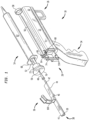
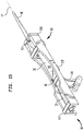
    • Figure 1 is a schematic isometric perspective of an insertion device of the present invention, partially exploded, showing the plunger of the syringe in position prior to attachment of the guidewire feed module;
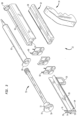
    • Figure 2 is an exploded schematic isometric perspective of an insertion device of the present invention;
    • Figure 3 is an exploded schematic isometric perspective of an insertion device of the present invention, showing details of the finger flange retention clip which retains the syringe upon the body while fixing the finger flange of the syringe in location longitudinally;
    • Figures 4 and 5 illustrate the details of the syringe retention ring at the front of the body;
    • Figures 6 and 7 illustrate the details of the syringe retention clip at the rear of the body;
    • Figure 8 is a schematic isometric perspective of a wire guide feed module suitable for use with an insertion device of the present invention;
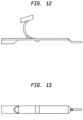
    • Figures 9 - 13 illustrate the details of the wire guide feed module of Figure 8 particularly illustrating the medial salient preferred for enhanced haptics during wire manipulation;
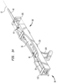
    • Figures 14 and 15 illustrate the lower surface of the wire guide feed of Figures 8 - 13 when mounted in a wire guide feed mounting fixture or retainer making it possible to mount the wire guide feed and a large cassette on the actuator carriage rather than the syringe when the cassette is of a size which is less conducive to mounting on the plunger of the syringe;
    • Figures 16 - 21 illustrate the details of the wire guide feed mounting fixture or retainer of Figures 14 and 15 ;
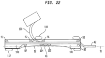
    • Figure 22 is a schematic illustrating the details of the click to fit retention mechanism for holding the wire guide feed of Figures 8 -13 in the wire guide feed mounting fixture or retainer of Figures 14 - 21;
    • Figure 23 is a schematic isometric perspective of an insertion device of the present invention with the syringe just above the mating clips on the body and actuating carriage;
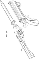
    • Figure 24 is a schematic isometric perspective of a wire guide feed mounting fixture illustrating mounting thereof on the actuating carriage prior to insertion of the wire guide feed;
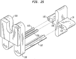
    • Figure 25 is an enlarged schematic isometric perspective of the wire guide feed mounting fixture of Figure 24 illustrating details of the mounting mechanism preventing incorrect mounting of the retainer on the actuating carriage prior to insertion of the wire guide feed module;
    • Figure 26 is a schematic isometric perspective illustrating an alternative insertion device of the present invention which is configured to allow the operator to positively and quickly mount the syringe on the insertion device;
    • Figure 27 is a detail drawing of the schematic isometric perspective of Figure 26 illustrating the interaction of the finger flange on the syringe with its mating groove in the body;
    • Figure 28 is a detail drawing of the schematic isometric perspective of Figure 26 illustrating the interaction of the plunger flange with the plunger flange clip;
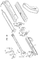
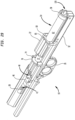
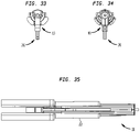
    • Figures 29 and 30 illustrate an alternative embodiment of the present invention which many clinicians may find preferable ergonomically as it positions the wire control surface above the trigger mechanism with the wire control surface facing upwardly so that the wire is more easily engaged by the flat of the digit rather than the tip of the digit as in the previous embodiment;
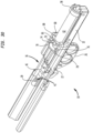
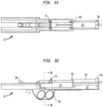
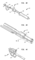
    • Figures 31 - 37 are respectively a plan view, a right side elevation, a rear elevation, a front elevation, a bottom view, a sectional view along line 36 - 36 in Figure 32 , and a left side elevation of the alternative embodiment of Figures 29 and 30 ;
    • Figures 38 -40 are exploded views of the embodiment illustrated in Figure 30 ;
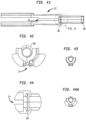
    • Figures 41 - 55 are detail views illustrating securement of the barrel, plunger and guidewire attachments for the embodiment of Figures 29 and 30 , in particular Figure 48 is a detail of finger flange slot 68 in Figure 39 , while Figure 44 is a detail of Figure 41 illustrating finger flange slot 68 with finger flange 66 in situ and Figure 43 is a sectional view along line 43-43 of Figure 45 , Figure 50 is a sectional view along line 50-50 of Figure 54 ;
    • Figures 56 and 57 illustrate how suction can be supplied to the syringe barrel by drawing finger rings rearwardly as shown in Figure 56 and how the plunger of the syringe can be advanced by moving finger rings forwardly as in Figure 57 , which should normally only be done with the syringe out of the body as when the clinician feels that a new start is desirable;
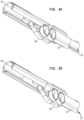
    • Figure 58 illustrates an embodiment of the invention having a "hilt handle" configuration;
    • Figure 59 illustrates the hilt handle embodiment of the invention of Figure 58 with the slider advanced as would be usual at the beginning of a Seldinger Procedure, while in Figure 58 , the slider has been retracted to induce a slight vacuum in the syringe allowing the practitioner to determine when the needle has entered a fluid filled region, while in making it possible to use the other hand to manipulate an ultrasound for confirmation that the needle is properly positioned;
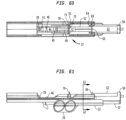
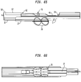
    • Figures 60-66 are respectively a plan view, front elevation, a sectional view taken along 62 - 62 in Figure 61 , a left side elevation, a right side elevation, a rear elevation, and a bottom view of the embodiments of Figures 58 and 59 ;
    • Figure 67 is an exploded view of the embodiment of Figures 58 and 59 ;
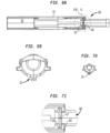
    • Figures 68-76 are detail views illustrating mounting features for ensuring reliable, hold fast, snap-into-position placement of the flange on the barrel of the syringe, in particular Figure 76 is a detail of finger flange slot 68 in Figure 67 , while Figure 71 is a detail of Figure 68 illustrating finger flange slot 68 with finger flange 66 in situ and Figure 70 is a sectional view along line 70-70 of Figure 73 ;
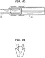
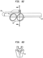
    • Figures 77-83 are detail views illustrating mounting features for ensuring reliable, hold fast, snap-into-position placement of the flange on the plunger of the syringe; and
    • Figures 84-85 are lower perspective views illustrating the fixture of the present invention with the slider in the rearward and frontal positions respectively.
    Description of Preferred Embodiments
  • The invention is described in detail below with reference to several embodiments and numerous examples. Such discussion is for purposes of illustration only. Modifications to particular examples within the spirit and scope of the present invention, set forth in the appended claims, will be readily apparent to one of skill in the art. Terminology used herein is given its ordinary meaning consistent with the exemplary definitions set forth immediately below.
  • With respect to the various ranges set forth herein, any upper limit recited may, of course, be combined with any lower limit for selected sub-ranges.
  • The transitional phrase "consisting essentially of" limits the scope of a claim to the specified materials or steps "and those that do not materially affect the basic and novel characteristic(s)" of the claimed invention. As used herein with respect to article claims, "consisting essentially of" and like terminology refers to the recited components and excludes other components which would substantially change the basic and novel characteristics of the article. Unless otherwise indicated or readily apparent, an article consists essentially of the recited components when the article includes 90% or more by weight of the recited components. That is, the terminology excludes more than 10% unrecited components.
  • In Figures 1 through 8 , insertion device 10 is adapted to allow one-handed insertion of guidewire 12. Guidewire 12 is commonly disposed within generally annular cassette 14 having exit opening 16. Insertion device 10 comprises body 22 with longitudinally extending guideway 24 defined therethrough. Actuator 28 sliding within longitudinally extending guideway 24 has trigger 26 mounted thereupon which trigger 26 slides within longitudinally extending slot 30 defined in lower forward portion 32 of body 22. Rearwardly extending handle 34 attached to body 22 is highly relieved.
  • Guidewire 12 may be withdrawn from generally annular cassette 14 through wire guide feed module 36 mounted thereupon at exit 16. Wire guide feed module 36 comprises: receiver 38 adapted to couple with exit 16 of generally annular cassette 14; rear wire guide 39 having rear tube 41 defined therethrough; forward guide fitting 40 comprising forward tube 42 with feed surface 44 being defined between rear tube 41 and forward tube 42. Preferably medial ridge or salient 46 is defined on feed surface 44 to ease and facilitate handling and control of guidewire 12. Forward guide fitting 40 is adapted to mate with adapter cone 48 which is capable of penetrating and being frictionally retained within guide wire passage 50 of plunger 52 of syringe 54 which is carried in groove 56 defined atop body 22 of insertion device 10. Syringe 54 is retained in position by forward ring 58 and barrel clip 60 grasping barrel 62 of syringe 54. Longitudinal movement of barrel 62 of syringe 54 is restrained by finger flange stop 64 located just rearwardly of barrel clip 60 such that finger flange 66 is trapped between finger flange stop 64 and barrel clip 60. Finger flange 66 rests within finger flange slot 68. Plunger flange 70 is joined to plunger 52 via plunger header 72. Plunger flange clip 74 mounted on actuator 28 grasps plunger flange 70 between arms 76 and 78 defining groove 77 so that plunger 52 may be advanced or withdrawn within barrel 62 by manipulation of trigger 26. As shown in Figures 6 and 7 , resilient arms 80 and 82 of barrel clip 60 embrace more than 180° of the circumference of barrel 62 urging it downwardly into groove 56 atop body 22 of insertion device 10 while forward ring 58 further restrains both lateral and longitudinal motion of barrel 62.
  • Dimensions, configuration and orientation of the foregoing parts are chosen such that when actuator 28, sliding along guideway 24 in body 22, is somewhat retracted from body 22 of insertion device 10, feed surface 44 for guidewire 12, and particularly medial ridge 46, is conveniently reachable by the digit of the hand grasping handle 34 while another digit of that same hand controls trigger 26. (Throughout this specification and claims, where we refer to "digit" we are referring to the digits of the hand, particularly any of the fingers or the thumb.) Accordingly, guidewire 12 located within guidewire cassette 14 may be drawn through guidewire exit opening 16 as the tip of the digit on the hand grasping handle 34 urges guidewire 12 forwardly or rearwardly by forward or rearward movement across medial ridge and guidewire 12 may be thereby advanced into the vessel/cavity with the operator being able to accurately sense the degree or amount of resistance guidewire 12 encounters as it is being advanced.
  • Figure 8 is an illustration of a guidewire cassette 14 having guidewire 12 disposed therein with wire guide feed module 36 attached to exit 16 of guidewire cassette with wire 12 extending across feed surface 44 and medial ridge 46 through forward tube 42 in forward guide fitting 40 thence through adapter cone 48.
  • Figures 9 through 13 illustrate a hand-held device for feeding a spring wire guide substantially similar to that described in Fleck, USP 5,125,906 which we have described as wire guide feed module 36 herein.
  • In many cases, it will be possible to mount wire guide feed module 36 directly on plunger 52 by insertion of adapter cone 48 into guidewire passage 50 in plunger 52, particularly when the length of wire 12 required is relatively short and accordingly cassette 14 can be relatively light and thus be capable of being retained in position by frictional forces between forward guide fitting 40, adapter cone 48 and plunger 52. However, in some cases, a more robust mounting method is appropriate such as, for example when the weight of cassette 14 is too great or when pressure might be applied to wire guide feed module 36. For such occasions, we provide retainer 88 as illustrated in Figures 14 through 22 which is capable of being mounted on actuator 28. In such cases, however it is necessary to ensure that the operator has open, or as near to unrestricted as may be practicable, access to wires 12 as it passes over medial ridge 46 in feed surface 44 of wire guide feed module 36. Wire guide feed module 36 can be introduced into retainer 88 longitudinally, snapping into place when properly positioned thereby providing haptic feedback to the operator confirming completion of proper insertion.
  • As shown in Figure 16, right sidewall 90 of retainer 88 has positioning protrusions 92 placed to locate wire guide feed module 36. Figures 19 and 20 illustrate the configuration of positioning protrusions 92 which generally have the shape of one fourth of a sphere with relieved flanks 94 as shown in Figure 20 which help to guide wire guide feed module 36 into position. Notably protrusion 96 will bear against forward surface 98 of cassette mounting pylon 100, while protrusions 102 will bear against medial ridge 46 and protrusions 104 will snap into position as soon as medial ridge 46 has advanced into position. In the embodiment shown in Figures 14 through 22 , adapter cone 48 is disposed within retainer 88. In alternative embodiments, it may be disposed forwardly of wall 106 of retainer 88. In Figure 21, retainer 88 is shown with left side wall 108 in position with crossbar 110 preventing over insertion of wire guide feed module 36 into retainer 88 by interference with pylon 100. Notably, sidewalls 90 and 108 are highly scarfed away adjacent medial ridge 46 to allow the operator free access thereto. In Figure 22 , it can be appreciated how crossbar 112 prevents improper insertion of wire guide feed module 36, while crossbar 110 prevents over insertion and protrusions 102 and 104 signal complete insertion hapticly to the operator. It can also be appreciated that access to medial ridge 46 and guidewire 12 passing thereover is facilitated by scarfing the way of medial portion of sidewalls 90 and 108.
  • Figure 23 illustrates an assembled insertion device 10 with syringe 54 disposed thereabove. It can be appreciated how forward end 120 of syringe 54 will be restrained by forward retention ring 58 while finger flange 66 and barrel 62 will be restrained by finger flange stop 64, finger flange slot 68 and barrel clip 60 while plunger flange 70 is restrained by arms 76 and 78 of plunger flange clip 74.
  • In Figures 24 and 25 , mounting recesses 114 and 115 have been provided in actuator 28 whereby pin 116 and slat 117 on mounting arms 118 may be inserted to mount retainer 88 fast to actuator 28 with details being illustrated in Figure 25 . Inasmuch as slat 117 is too large, too wide, to be inserted into mounting recess 115, improper mounting of retainer 88 and guidewire cassette 14 is thereby prevented. Alternatively, insertion device 10 can be provided with retainer 88 permanently attached to actuator carriage 28.
  • Figures 26 through 28 illustrate a variant of the insertion device 10 of the present invention meant for situations such as emergency rooms in which the operator may be required to assemble the insertion device 10, syringe 54, wire guide feed module 36 and cassette 14 with considerable urgency. It can be appreciated that retention ring 58 has been replaced by retention cone 86, while finger flange stop 64, barrel clip 60 and plunger flange clip 74 have been provided with exterior guides 64G, 60G and 74G to facilitate rapid insertion of the mating portions of syringe 54 thereinto. Figure 27 illustrates how finger flange 66 can be mounted either horizontally or vertically in finger flange slot 68. Similarly, Figure 28 illustrates mating of plunger flange 70 with plunger flange clip 74.
  • Figures 29 through 38 illustrate a manufacturing design for a hilt grip fixture of the present invention wherein parts performing the same function are given the same numbers as those performing that function in the conceptual design of a pistol grip fixture illustrated in Figures 1 through 28 . It will be apparent that the primary difference between the two designs is that the grip is incorporated into body 22 of the fixture of Figures 29 - 38 and adapter/receiver 36 for annular wire cassette 14 is oriented with feed surface 44 oriented upwardly so that a clinician holding fixture 10 is able to manipulate guidewire 12 with the flat of his digit while using his index finger to advance and retract actuator 28 while engaging plunger flange 70 of syringe 54 providing an enhanced haptic feel to evaluate resistance being met by guidewire 12 as it is advanced into the body.
  • In Figure 29 , the handle of the previous embodiment is largely dispensed with leaving only trigger 26 directly connected to actuator 28 deployed directly under body 22 such that, when a digit of one hand extends through trigger 26, the ball of the thumb of that hand easily falls on medial ridge 46 over which guidewire 12 is passed allowing the clinician to advance the guidewire 12 while retaining good tactile feel for the resistance being encountered. It should be observed that in the embodiment of Figures 29 and 30 , flanges 66 and 70 are well secured in slots 68 and 74 respectively, while barrel 62 of syringe 54 is secured by forward ring 58, thereby providing positive location of syringe 54. It should be noted that in the embodiment of Figures 29-30 , the hand engages the fixture much like a hand would grasp the hilt of a sword.
  • Figures 31-37 illustrate details of the internal construction of the fixture of the present invention, note particularly "T"-shaped longitudinal channel 24 (See also Fig.42 ) formed in body 22 as shown in Figure 36 so that actuator 28, having mating "T" shaped portion 25 as shown in Figure 40 , may be advanced and retracted therealong. In Figures 38 and 39 , the fixture has been disassembled illustrating how the constituent parts are assembled.
  • Figures 41-48 illustrate other details of the constituent parts. Note longitudinally extending guideway 24 formed in body 22 to restrain movement of slider/actuator 28 thereupon. Note also undercut slot 68 in body 22 engages finger flange 66 for positive positioning thereof. In Figures 49-55 , details of retention slot 74 having undercut groove 77 for marrying plunger flange 70 to actuator 28 are illustrated. Note again that retention slot 74 encompasses slightly more than 180° of plunger flange 70 thereby enabling positive positioning between the two by virtue of the elasticity of plunger flange 70 and, to a lesser extent, slider actuator 28. Note also the longitudinal undercut as illustrated in Figure 54 . As shown in Figures 42, 44 , 48 , the undercut of groove 77 accommodates the conventional cupping of plunger flange 70 further fixing the relative position thereof.
  • Figures 56 and 57 are lower perspectives illustrating motion of slider/actuator 28 along longitudinally extending guideway 24 in body 22 with Figure 56 illustrating actuator 28 as rearwardly positioned to induce partial vacuum in syringe 54.
  • Figures 58 and 59 illustrate still another embodiment of the present invention in which shield/hood 97 positively prevents improper insertion of generally annular guidewire cassette 14 (not shown) when generally annular guidewire cassette 14 enters through tunnel 95.
  • In Figures 60-66 , details of the internal construction of the fixture are illustrated. Note that longitudinally extending guideway 24 is now incorporated into slider/actuator 28 as shown in Figure 62 .
  • In Figure 67 , note that ramp 99 interlockingly mates with pylon 100 of wire guide feed module 36 for more positive positioning thereof back to slider/actuator 28.
  • In Figures 68-76 , details of construction of body 22 are illustrated. Particularly note that in Figure 71 , finger flange slot 68 is longitudinally undercut with undercut groove 67 accepting finger flange 66 to positively position finger flange 66 in body 22 while flexible wall 63 serves to more positively lock finger flange 66 into position in finger flange slot 68. Note also that T-Bar 25 is formed in body 22 in this embodiment while slot 24 is formed in slider/actuator 28.
  • In Figures 77-83 , details of the construction of slider/actuator 28 are illustrated. Note particularly that groove 77 engages more than 180° of plunger flange 70 in interference fit to more positively position plunger flange 70 respect to slider/actuator 28.
  • In Figures 84-85 , a lower perspective illustrates slider/actuator 28 in a rearward position ( Figure 84 ) as well as a forward position ( Figure 85 ).
  • While the invention has been described in detail, modifications within the spirit and scope of the invention will be readily apparent to those of skill in the art. In view of the foregoing discussion, relevant knowledge in the art and references discussed above in connection with the Background and Detailed Description further description is deemed unnecessary. In addition, it should be understood that aspects of the invention and portions of various embodiments may be combined or interchanged either in whole or in part. Furthermore, those of ordinary skill in the art will appreciate that the foregoing description is by way of example only, and is not intended to limit the invention.

Claims (3)

  1. A device for one-handed insertion of a guidewire into the lumen of a vessel or other cavity, comprising:
    a body (22) having:
    a grip formed in said body (22) or attached thereto,
    a guideway (24),
    a barrel clip (60) mounted on said body adapted to receive and retain the barrel (62) of a syringe (54);
    a syringe (54) having a barrel (62) and a finger flange (66), said syringe (54) being retained by said barrel clip (60);
    a plunger (52) having a plunger flange (70) and a guidewire passage (50) therethrough and a hollow needle co-linear with said guidewire passage (50) through said plunger (52);
    an actuator (28) slidable along said guideway (24), having attached thereto:
    a trigger (26),
    a plunger flange clip (74) adapted to grasp the plunger flange (70) of said plunger (52) of said syringe (54),
    a rear wire control tube (41),
    a forward wire control tube (42) ,
    a wire feed surface (44) between said rear wire control tube (41) and said forward wire control tube (42)
    wherein said grip, said trigger (26) and said wire feed surface (44) are disposed such that when the grip is engaged by digits of one hand, a digit of said one hand is able to advance the guidewire through said syringe (54) by engaging the guidewire between the digit of said one hand and the wire feed surface (44), sensing a degree of resistance encountered by a tip of said guidewire, with another digit of said one hand being able to urge the trigger (26) of said syringe (54) rearwardly and/or forwardly, drawing said plunger (52) rearwardly and/or forwardly while said digits of said one hand continue to engage said grip.
  2. The device according to claim 1, wherein the body (22) is slidably coupled to the actuator (28) by way of a guideway (24) formed in either the body (22) or actuator (28).
  3. The device according to claim 1 or 2, wherein the hollow needle is joined to said syringe (54).
EP22000213.3A 2016-11-10 2017-11-10 Insertion device for one-handed insertion of a guidewire into the lumen of a vessel/cavity Pending EP4137192A1 (en)

Applications Claiming Priority (3)

Application Number Priority Date Filing Date Title
US201662420269P 2016-11-10 2016-11-10
EP17869129.1A EP3538193B1 (en) 2016-11-10 2017-11-10 Insertion device for one-handed insertion of a guidewire into the lumen of a vessel/cavity
PCT/US2017/061046 WO2018089758A1 (en) 2016-11-10 2017-11-10 Insertion device for one-handed insertion of a guidewire into the lumen of a vessel/cavity

Related Parent Applications (1)

Application Number Title Priority Date Filing Date
EP17869129.1A Division EP3538193B1 (en) 2016-11-10 2017-11-10 Insertion device for one-handed insertion of a guidewire into the lumen of a vessel/cavity

Publications (1)

Publication Number Publication Date
EP4137192A1 true EP4137192A1 (en) 2023-02-22

Family

ID=62109983

Family Applications (2)

Application Number Title Priority Date Filing Date
EP17869129.1A Active EP3538193B1 (en) 2016-11-10 2017-11-10 Insertion device for one-handed insertion of a guidewire into the lumen of a vessel/cavity
EP22000213.3A Pending EP4137192A1 (en) 2016-11-10 2017-11-10 Insertion device for one-handed insertion of a guidewire into the lumen of a vessel/cavity

Family Applications Before (1)

Application Number Title Priority Date Filing Date
EP17869129.1A Active EP3538193B1 (en) 2016-11-10 2017-11-10 Insertion device for one-handed insertion of a guidewire into the lumen of a vessel/cavity

Country Status (5)

Country Link
US (2) US11260206B2 (en)
EP (2) EP3538193B1 (en)
JP (2) JP7015843B2 (en)
CA (1) CA3043614A1 (en)
WO (1) WO2018089758A1 (en)

Families Citing this family (5)

* Cited by examiner, † Cited by third party
Publication number Priority date Publication date Assignee Title
JP7015843B2 (en) * 2016-11-10 2022-02-03 イーブイエイ・イノベーションズ Insertion device for inserting a guide wire into the lumen / lumen of a vessel with one hand
JP7151252B2 (en) 2018-08-01 2022-10-12 住友ベークライト株式会社 medical inserter
BR112022020408A2 (en) 2020-04-23 2022-11-22 Bard Access Systems Inc QUICK INSERTION CENTRAL CATHETERS INCLUDING CATHETER SETS
AU2021303150A1 (en) * 2020-06-29 2023-02-02 Bard Access Systems, Inc. Rapidly insertable central catheters including catheter assemblies and methods thereof
WO2023200943A1 (en) * 2022-04-14 2023-10-19 The Regents Of The University Of Michigan Medical device for guidewire placement and related method

Citations (3)

* Cited by examiner, † Cited by third party
Publication number Priority date Publication date Assignee Title
US5125906A (en) 1990-11-02 1992-06-30 Arrow International Investment Corporation Hand-held device for feeding a spring wire guide
WO1999012600A1 (en) * 1997-09-09 1999-03-18 Becton Dickinson Critical Care Systems Pte Limited Guide wire introducer
WO2014118172A1 (en) * 2013-01-31 2014-08-07 Ventinova Medical B.V. Catheter with positioning system

Family Cites Families (12)

* Cited by examiner, † Cited by third party
Publication number Priority date Publication date Assignee Title
US4747831A (en) * 1987-04-29 1988-05-31 Phase Medical, Inc. Cannula insertion set with safety retracting needle
US7150724B2 (en) * 2002-06-05 2006-12-19 Cardinal Health 303, Inc. Syringe plunger driver system
JP2008023128A (en) 2006-07-21 2008-02-07 Terumo Corp Guidewire supply instrument and guidewire insertion instrument
US9956382B2 (en) * 2011-12-29 2018-05-01 Yonsei University Wonju Industry—Academic Cooperation Foundation Guide wire insertion apparatus used in catheterization
EP2961462A4 (en) * 2013-02-27 2017-01-18 The George Washington University Ultrasound assisted catheter placement system
JP2014212906A (en) 2013-04-25 2014-11-17 日本コヴィディエン株式会社 Guide wire insertion aid
CA2955841C (en) * 2014-09-10 2017-06-27 Vascular Solutions, Inc. Capture assembly and method
CA2962811A1 (en) * 2014-10-14 2016-04-21 Sanford Health Anchoring guidewire
US10238790B2 (en) * 2015-03-06 2019-03-26 Carefusion 2200, Inc. Syringe holder
US11027099B2 (en) * 2015-04-30 2021-06-08 Smiths Medical Asd, Inc. Vascular access device
CN109640833A (en) * 2016-04-17 2019-04-16 阿坎塔医疗有限责任公司 Device and method for singlehanded intervention and insertion article
JP7015843B2 (en) * 2016-11-10 2022-02-03 イーブイエイ・イノベーションズ Insertion device for inserting a guide wire into the lumen / lumen of a vessel with one hand

Patent Citations (3)

* Cited by examiner, † Cited by third party
Publication number Priority date Publication date Assignee Title
US5125906A (en) 1990-11-02 1992-06-30 Arrow International Investment Corporation Hand-held device for feeding a spring wire guide
WO1999012600A1 (en) * 1997-09-09 1999-03-18 Becton Dickinson Critical Care Systems Pte Limited Guide wire introducer
WO2014118172A1 (en) * 2013-01-31 2014-08-07 Ventinova Medical B.V. Catheter with positioning system

Also Published As

Publication number Publication date
EP3538193A4 (en) 2020-07-29
CA3043614A1 (en) 2018-05-17
JP2022125001A (en) 2022-08-26
WO2018089758A1 (en) 2018-05-17
EP3538193B1 (en) 2022-10-19
JP7224426B2 (en) 2023-02-17
US20220126068A1 (en) 2022-04-28
US11260206B2 (en) 2022-03-01
US20190282788A1 (en) 2019-09-19
JP7015843B2 (en) 2022-02-03
US11819643B2 (en) 2023-11-21
JP2019535469A (en) 2019-12-12
EP3538193A1 (en) 2019-09-18

Similar Documents

Publication Publication Date Title
US11819643B2 (en) Insertion device for one-handed insertion of a guidewire into the lumen of a vessel/cavity
JP7249382B2 (en) catheter insertion device
US20210008347A1 (en) Catheter assembly with segmented stabilization system
CN112190816B (en) Assembled venous catheter device
US6398743B1 (en) Medical device for inserting a guide wire having a retractable needle
JP6600377B2 (en) Catheter insertion device
US5685855A (en) Protected needle catheter placement device with sampling provisions and method for its use
US9616201B2 (en) Intravenous catheter and insertion device with reduced blood spatter
US20150051584A1 (en) Catheter insertion device
US20050027256A1 (en) Medical device with shield having a retractable needle
US8512363B2 (en) Channeled wire guide for a scalpel
JPH02177952A (en) Surgical instrument and assembly thereof
JP4393885B2 (en) Guide wire feeder and guide wire inserter
JP2008023128A (en) Guidewire supply instrument and guidewire insertion instrument
US20220203075A1 (en) Wire And Catheter Placement Device
CN117881452A (en) Catheter with integrated dispenser and related manufacturing method
WO2023200943A1 (en) Medical device for guidewire placement and related method
CN116916996A (en) Wire and catheter placement device
JP2008036173A (en) Guide wire feeder and guide wire insertion device
MXPA97005013A (en) Needle probe placement device protected with sampling provisions and metodopara su

Legal Events

Date Code Title Description
PUAI Public reference made under article 153(3) epc to a published international application that has entered the european phase

Free format text: ORIGINAL CODE: 0009012

STAA Information on the status of an ep patent application or granted ep patent

Free format text: STATUS: THE APPLICATION HAS BEEN PUBLISHED

AC Divisional application: reference to earlier application

Ref document number: 3538193

Country of ref document: EP

Kind code of ref document: P

AK Designated contracting states

Kind code of ref document: A1

Designated state(s): AL AT BE BG CH CY CZ DE DK EE ES FI FR GB GR HR HU IE IS IT LI LT LU LV MC MK MT NL NO PL PT RO RS SE SI SK SM TR

STAA Information on the status of an ep patent application or granted ep patent

Free format text: STATUS: REQUEST FOR EXAMINATION WAS MADE

17P Request for examination filed

Effective date: 20230822

RBV Designated contracting states (corrected)

Designated state(s): AL AT BE BG CH CY CZ DE DK EE ES FI FR GB GR HR HU IE IS IT LI LT LU LV MC MK MT NL NO PL PT RO RS SE SI SK SM TR