EP4137101A1 - Bile duct stent and manufacturing method thereof - Google Patents
Bile duct stent and manufacturing method thereof Download PDFInfo
- Publication number
- EP4137101A1 EP4137101A1 EP21788864.3A EP21788864A EP4137101A1 EP 4137101 A1 EP4137101 A1 EP 4137101A1 EP 21788864 A EP21788864 A EP 21788864A EP 4137101 A1 EP4137101 A1 EP 4137101A1
- Authority
- EP
- European Patent Office
- Prior art keywords
- backflow
- pin
- pattern film
- preventing pattern
- metal wires
- Prior art date
- Legal status (The legal status is an assumption and is not a legal conclusion. Google has not performed a legal analysis and makes no representation as to the accuracy of the status listed.)
- Pending
Links
Images


Classifications
-
- A—HUMAN NECESSITIES
- A61—MEDICAL OR VETERINARY SCIENCE; HYGIENE
- A61F—FILTERS IMPLANTABLE INTO BLOOD VESSELS; PROSTHESES; DEVICES PROVIDING PATENCY TO, OR PREVENTING COLLAPSING OF, TUBULAR STRUCTURES OF THE BODY, e.g. STENTS; ORTHOPAEDIC, NURSING OR CONTRACEPTIVE DEVICES; FOMENTATION; TREATMENT OR PROTECTION OF EYES OR EARS; BANDAGES, DRESSINGS OR ABSORBENT PADS; FIRST-AID KITS
- A61F2/00—Filters implantable into blood vessels; Prostheses, i.e. artificial substitutes or replacements for parts of the body; Appliances for connecting them with the body; Devices providing patency to, or preventing collapsing of, tubular structures of the body, e.g. stents
- A61F2/0077—Special surfaces of prostheses, e.g. for improving ingrowth
-
- A—HUMAN NECESSITIES
- A61—MEDICAL OR VETERINARY SCIENCE; HYGIENE
- A61F—FILTERS IMPLANTABLE INTO BLOOD VESSELS; PROSTHESES; DEVICES PROVIDING PATENCY TO, OR PREVENTING COLLAPSING OF, TUBULAR STRUCTURES OF THE BODY, e.g. STENTS; ORTHOPAEDIC, NURSING OR CONTRACEPTIVE DEVICES; FOMENTATION; TREATMENT OR PROTECTION OF EYES OR EARS; BANDAGES, DRESSINGS OR ABSORBENT PADS; FIRST-AID KITS
- A61F2/00—Filters implantable into blood vessels; Prostheses, i.e. artificial substitutes or replacements for parts of the body; Appliances for connecting them with the body; Devices providing patency to, or preventing collapsing of, tubular structures of the body, e.g. stents
- A61F2/02—Prostheses implantable into the body
- A61F2/04—Hollow or tubular parts of organs, e.g. bladders, tracheae, bronchi or bile ducts
-
- A—HUMAN NECESSITIES
- A61—MEDICAL OR VETERINARY SCIENCE; HYGIENE
- A61F—FILTERS IMPLANTABLE INTO BLOOD VESSELS; PROSTHESES; DEVICES PROVIDING PATENCY TO, OR PREVENTING COLLAPSING OF, TUBULAR STRUCTURES OF THE BODY, e.g. STENTS; ORTHOPAEDIC, NURSING OR CONTRACEPTIVE DEVICES; FOMENTATION; TREATMENT OR PROTECTION OF EYES OR EARS; BANDAGES, DRESSINGS OR ABSORBENT PADS; FIRST-AID KITS
- A61F2/00—Filters implantable into blood vessels; Prostheses, i.e. artificial substitutes or replacements for parts of the body; Appliances for connecting them with the body; Devices providing patency to, or preventing collapsing of, tubular structures of the body, e.g. stents
- A61F2/82—Devices providing patency to, or preventing collapsing of, tubular structures of the body, e.g. stents
- A61F2/856—Single tubular stent with a side portal passage
-
- A—HUMAN NECESSITIES
- A61—MEDICAL OR VETERINARY SCIENCE; HYGIENE
- A61F—FILTERS IMPLANTABLE INTO BLOOD VESSELS; PROSTHESES; DEVICES PROVIDING PATENCY TO, OR PREVENTING COLLAPSING OF, TUBULAR STRUCTURES OF THE BODY, e.g. STENTS; ORTHOPAEDIC, NURSING OR CONTRACEPTIVE DEVICES; FOMENTATION; TREATMENT OR PROTECTION OF EYES OR EARS; BANDAGES, DRESSINGS OR ABSORBENT PADS; FIRST-AID KITS
- A61F2/00—Filters implantable into blood vessels; Prostheses, i.e. artificial substitutes or replacements for parts of the body; Appliances for connecting them with the body; Devices providing patency to, or preventing collapsing of, tubular structures of the body, e.g. stents
- A61F2/82—Devices providing patency to, or preventing collapsing of, tubular structures of the body, e.g. stents
- A61F2/86—Stents in a form characterised by the wire-like elements; Stents in the form characterised by a net-like or mesh-like structure
- A61F2/90—Stents in a form characterised by the wire-like elements; Stents in the form characterised by a net-like or mesh-like structure characterised by a net-like or mesh-like structure
-
- A—HUMAN NECESSITIES
- A61—MEDICAL OR VETERINARY SCIENCE; HYGIENE
- A61L—METHODS OR APPARATUS FOR STERILISING MATERIALS OR OBJECTS IN GENERAL; DISINFECTION, STERILISATION OR DEODORISATION OF AIR; CHEMICAL ASPECTS OF BANDAGES, DRESSINGS, ABSORBENT PADS OR SURGICAL ARTICLES; MATERIALS FOR BANDAGES, DRESSINGS, ABSORBENT PADS OR SURGICAL ARTICLES
- A61L31/00—Materials for other surgical articles, e.g. stents, stent-grafts, shunts, surgical drapes, guide wires, materials for adhesion prevention, occluding devices, surgical gloves, tissue fixation devices
- A61L31/02—Inorganic materials
- A61L31/022—Metals or alloys
-
- A—HUMAN NECESSITIES
- A61—MEDICAL OR VETERINARY SCIENCE; HYGIENE
- A61L—METHODS OR APPARATUS FOR STERILISING MATERIALS OR OBJECTS IN GENERAL; DISINFECTION, STERILISATION OR DEODORISATION OF AIR; CHEMICAL ASPECTS OF BANDAGES, DRESSINGS, ABSORBENT PADS OR SURGICAL ARTICLES; MATERIALS FOR BANDAGES, DRESSINGS, ABSORBENT PADS OR SURGICAL ARTICLES
- A61L31/00—Materials for other surgical articles, e.g. stents, stent-grafts, shunts, surgical drapes, guide wires, materials for adhesion prevention, occluding devices, surgical gloves, tissue fixation devices
- A61L31/14—Materials characterised by their function or physical properties, e.g. injectable or lubricating compositions, shape-memory materials, surface modified materials
-
- B—PERFORMING OPERATIONS; TRANSPORTING
- B21—MECHANICAL METAL-WORKING WITHOUT ESSENTIALLY REMOVING MATERIAL; PUNCHING METAL
- B21F—WORKING OR PROCESSING OF METAL WIRE
- B21F45/00—Wire-working in the manufacture of other particular articles
-
- B—PERFORMING OPERATIONS; TRANSPORTING
- B21—MECHANICAL METAL-WORKING WITHOUT ESSENTIALLY REMOVING MATERIAL; PUNCHING METAL
- B21F—WORKING OR PROCESSING OF METAL WIRE
- B21F45/00—Wire-working in the manufacture of other particular articles
- B21F45/008—Wire-working in the manufacture of other particular articles of medical instruments, e.g. stents, corneal rings
-
- A—HUMAN NECESSITIES
- A61—MEDICAL OR VETERINARY SCIENCE; HYGIENE
- A61B—DIAGNOSIS; SURGERY; IDENTIFICATION
- A61B17/00—Surgical instruments, devices or methods, e.g. tourniquets
- A61B2017/00526—Methods of manufacturing
-
- A—HUMAN NECESSITIES
- A61—MEDICAL OR VETERINARY SCIENCE; HYGIENE
- A61F—FILTERS IMPLANTABLE INTO BLOOD VESSELS; PROSTHESES; DEVICES PROVIDING PATENCY TO, OR PREVENTING COLLAPSING OF, TUBULAR STRUCTURES OF THE BODY, e.g. STENTS; ORTHOPAEDIC, NURSING OR CONTRACEPTIVE DEVICES; FOMENTATION; TREATMENT OR PROTECTION OF EYES OR EARS; BANDAGES, DRESSINGS OR ABSORBENT PADS; FIRST-AID KITS
- A61F2/00—Filters implantable into blood vessels; Prostheses, i.e. artificial substitutes or replacements for parts of the body; Appliances for connecting them with the body; Devices providing patency to, or preventing collapsing of, tubular structures of the body, e.g. stents
- A61F2/01—Filters implantable into blood vessels
- A61F2/0105—Open ended, i.e. legs gathered only at one side
-
- A—HUMAN NECESSITIES
- A61—MEDICAL OR VETERINARY SCIENCE; HYGIENE
- A61F—FILTERS IMPLANTABLE INTO BLOOD VESSELS; PROSTHESES; DEVICES PROVIDING PATENCY TO, OR PREVENTING COLLAPSING OF, TUBULAR STRUCTURES OF THE BODY, e.g. STENTS; ORTHOPAEDIC, NURSING OR CONTRACEPTIVE DEVICES; FOMENTATION; TREATMENT OR PROTECTION OF EYES OR EARS; BANDAGES, DRESSINGS OR ABSORBENT PADS; FIRST-AID KITS
- A61F2/00—Filters implantable into blood vessels; Prostheses, i.e. artificial substitutes or replacements for parts of the body; Appliances for connecting them with the body; Devices providing patency to, or preventing collapsing of, tubular structures of the body, e.g. stents
- A61F2/02—Prostheses implantable into the body
- A61F2/24—Heart valves ; Vascular valves, e.g. venous valves; Heart implants, e.g. passive devices for improving the function of the native valve or the heart muscle; Transmyocardial revascularisation [TMR] devices; Valves implantable in the body
- A61F2/2476—Valves implantable in the body not otherwise provided for
-
- A—HUMAN NECESSITIES
- A61—MEDICAL OR VETERINARY SCIENCE; HYGIENE
- A61F—FILTERS IMPLANTABLE INTO BLOOD VESSELS; PROSTHESES; DEVICES PROVIDING PATENCY TO, OR PREVENTING COLLAPSING OF, TUBULAR STRUCTURES OF THE BODY, e.g. STENTS; ORTHOPAEDIC, NURSING OR CONTRACEPTIVE DEVICES; FOMENTATION; TREATMENT OR PROTECTION OF EYES OR EARS; BANDAGES, DRESSINGS OR ABSORBENT PADS; FIRST-AID KITS
- A61F2/00—Filters implantable into blood vessels; Prostheses, i.e. artificial substitutes or replacements for parts of the body; Appliances for connecting them with the body; Devices providing patency to, or preventing collapsing of, tubular structures of the body, e.g. stents
- A61F2/02—Prostheses implantable into the body
- A61F2/04—Hollow or tubular parts of organs, e.g. bladders, tracheae, bronchi or bile ducts
- A61F2002/041—Bile ducts
-
- A—HUMAN NECESSITIES
- A61—MEDICAL OR VETERINARY SCIENCE; HYGIENE
- A61F—FILTERS IMPLANTABLE INTO BLOOD VESSELS; PROSTHESES; DEVICES PROVIDING PATENCY TO, OR PREVENTING COLLAPSING OF, TUBULAR STRUCTURES OF THE BODY, e.g. STENTS; ORTHOPAEDIC, NURSING OR CONTRACEPTIVE DEVICES; FOMENTATION; TREATMENT OR PROTECTION OF EYES OR EARS; BANDAGES, DRESSINGS OR ABSORBENT PADS; FIRST-AID KITS
- A61F2210/00—Particular material properties of prostheses classified in groups A61F2/00 - A61F2/26 or A61F2/82 or A61F9/00 or A61F11/00 or subgroups thereof
- A61F2210/0014—Particular material properties of prostheses classified in groups A61F2/00 - A61F2/26 or A61F2/82 or A61F9/00 or A61F11/00 or subgroups thereof using shape memory or superelastic materials, e.g. nitinol
-
- A—HUMAN NECESSITIES
- A61—MEDICAL OR VETERINARY SCIENCE; HYGIENE
- A61F—FILTERS IMPLANTABLE INTO BLOOD VESSELS; PROSTHESES; DEVICES PROVIDING PATENCY TO, OR PREVENTING COLLAPSING OF, TUBULAR STRUCTURES OF THE BODY, e.g. STENTS; ORTHOPAEDIC, NURSING OR CONTRACEPTIVE DEVICES; FOMENTATION; TREATMENT OR PROTECTION OF EYES OR EARS; BANDAGES, DRESSINGS OR ABSORBENT PADS; FIRST-AID KITS
- A61F2230/00—Geometry of prostheses classified in groups A61F2/00 - A61F2/26 or A61F2/82 or A61F9/00 or A61F11/00 or subgroups thereof
- A61F2230/0002—Two-dimensional shapes, e.g. cross-sections
- A61F2230/0004—Rounded shapes, e.g. with rounded corners
- A61F2230/0008—Rounded shapes, e.g. with rounded corners elliptical or oval
-
- A—HUMAN NECESSITIES
- A61—MEDICAL OR VETERINARY SCIENCE; HYGIENE
- A61F—FILTERS IMPLANTABLE INTO BLOOD VESSELS; PROSTHESES; DEVICES PROVIDING PATENCY TO, OR PREVENTING COLLAPSING OF, TUBULAR STRUCTURES OF THE BODY, e.g. STENTS; ORTHOPAEDIC, NURSING OR CONTRACEPTIVE DEVICES; FOMENTATION; TREATMENT OR PROTECTION OF EYES OR EARS; BANDAGES, DRESSINGS OR ABSORBENT PADS; FIRST-AID KITS
- A61F2230/00—Geometry of prostheses classified in groups A61F2/00 - A61F2/26 or A61F2/82 or A61F9/00 or A61F11/00 or subgroups thereof
- A61F2230/0002—Two-dimensional shapes, e.g. cross-sections
- A61F2230/0028—Shapes in the form of latin or greek characters
- A61F2230/005—Rosette-shaped, e.g. star-shaped
-
- A—HUMAN NECESSITIES
- A61—MEDICAL OR VETERINARY SCIENCE; HYGIENE
- A61F—FILTERS IMPLANTABLE INTO BLOOD VESSELS; PROSTHESES; DEVICES PROVIDING PATENCY TO, OR PREVENTING COLLAPSING OF, TUBULAR STRUCTURES OF THE BODY, e.g. STENTS; ORTHOPAEDIC, NURSING OR CONTRACEPTIVE DEVICES; FOMENTATION; TREATMENT OR PROTECTION OF EYES OR EARS; BANDAGES, DRESSINGS OR ABSORBENT PADS; FIRST-AID KITS
- A61F2240/00—Manufacturing or designing of prostheses classified in groups A61F2/00 - A61F2/26 or A61F2/82 or A61F9/00 or A61F11/00 or subgroups thereof
- A61F2240/001—Designing or manufacturing processes
- A61F2240/002—Designing or making customized prostheses
-
- A—HUMAN NECESSITIES
- A61—MEDICAL OR VETERINARY SCIENCE; HYGIENE
- A61F—FILTERS IMPLANTABLE INTO BLOOD VESSELS; PROSTHESES; DEVICES PROVIDING PATENCY TO, OR PREVENTING COLLAPSING OF, TUBULAR STRUCTURES OF THE BODY, e.g. STENTS; ORTHOPAEDIC, NURSING OR CONTRACEPTIVE DEVICES; FOMENTATION; TREATMENT OR PROTECTION OF EYES OR EARS; BANDAGES, DRESSINGS OR ABSORBENT PADS; FIRST-AID KITS
- A61F2250/00—Special features of prostheses classified in groups A61F2/00 - A61F2/26 or A61F2/82 or A61F9/00 or A61F11/00 or subgroups thereof
- A61F2250/0014—Special features of prostheses classified in groups A61F2/00 - A61F2/26 or A61F2/82 or A61F9/00 or A61F11/00 or subgroups thereof having different values of a given property or geometrical feature, e.g. mechanical property or material property, at different locations within the same prosthesis
- A61F2250/0039—Special features of prostheses classified in groups A61F2/00 - A61F2/26 or A61F2/82 or A61F9/00 or A61F11/00 or subgroups thereof having different values of a given property or geometrical feature, e.g. mechanical property or material property, at different locations within the same prosthesis differing in diameter
Definitions
- the present invention relates to a bile duct stent and a method of manufacturing the same, and more particularly, to a bile duct stent for preventing the backflow of food in the duodenum and a method of manufacturing the same.
- a bile duct serves as a passage that allows bile, which is concentrated after being produced by the liver and stored in the gallbladder, to flow to the duodenum.
- a biliary stricture is a disease in which the bile duct is constricted and the passage is narrowed or blocked due to tumors such as pancreatitis/pancreatic cancer and cholangitis/cholangiocarcinoma.
- a biliary stricture can be treated with surgery, but endoscopic biliary stenting has been used in recent years.
- stenting is widely practiced when surgery is not possible due to the onset of a malignant biliary stricture in terminal cancer patients.
- Korean Patent Registration No. 0170220 discloses a stent having a backflow preventing means formed of tricuspid valve/ tricuspid valve type valves made of a resin material.
- valves disclosed in Korean Patent Registration No. 0170220 have a disadvantage in that, when an expansile force of the stent is weak or when the stent does not maintain a sufficiently expanded state, openings of the valves are not sufficiently opened and reach a closed state, thus obstructing the supply of bile and causing solidification of stagnant bile.
- the backflow preventing means is made of a resin material, there is a disadvantage in that durability is lowered due to an occurrence of film damage caused by bile as in the conventional tubular stent.
- Embodiments of the present invention are directed to providing a bile duct stent, in which a backflow-preventing pattern film utilizing a pattern member made of threads (Lasso) or metal wires is formed at a duodenum-side outlet of the stent, which is inserted into the bile duct, to prevent food in the duodenum from flowing back into the bile duct, and a method of manufacturing the same.
- a backflow-preventing pattern film utilizing a pattern member made of threads (Lasso) or metal wires is formed at a duodenum-side outlet of the stent, which is inserted into the bile duct, to prevent food in the duodenum from flowing back into the bile duct, and a method of manufacturing the same.
- a bile duct stent having a backflow preventing means
- the bile duct stent including: a cylindrical body having a mesh structure formed by zigzagging metal wires of a shape memory alloy on a plurality of pins each disposed in a circumferential direction (X) and a longitudinal direction (Y) of a cylindrical jig; a film portion coated on cells of the metal wires of the mesh structure; and a backflow-preventing pattern film in which a hole is formed in the film portion of each cell formed at an outlet end of the cylindrical body and threads (Lasso) fixed by zigzagging to the cells of the metal wires in the circumferential direction by passing through any one hole (h) cross the outlet end one time or more to form a network structure.
- Lasso threads
- a bile duct stent having a backflow preventing means
- the bile duct stent including: a cylindrical body having a mesh structure formed by zigzagging metal wires of a shape memory alloy on a plurality of pins each disposed in a circumferential direction (X) and a longitudinal direction (Y) of a cylindrical jig; and a backflow-preventing pattern film in which the metal wires are woven on a pin (P) and another pin (P) disposed in the circumferential direction (X) at a lower end of the jig and the metal wires cross an outlet end of the cylindrical body one time or more to form a network structure.
- the backflow-preventing pattern film may be formed as any one of a cross-shaped backflow-preventing pattern film, a straight backflow-preventing pattern film, a zigzag-shaped backflow-preventing pattern film, a polygonal backflow-preventing pattern film, and a star-shaped backflow-preventing pattern film in which the metal wires cross the outlet end and intersect each other.
- the backflow-preventing pattern film may be finished with a twist knot after one line of metal wires is continuously woven from a start-point pin (P) to an end-point pin (P) via at least one pin (P).
- one line of metal wires may be knotted by twisting at least once or more after a first line crossing the center of the outlet end from a first pin (P1), which is a start point, is woven on a second pin, extends and moves 90° in the circumferential direction, and is woven on a third pin, and then a second line crossing the outlet end from the third pin vertically intersects the first line and is woven on a fourth pin, which is an end point.
- P1 first pin
- P1 which is a start point
- the backflow-preventing pattern film may be formed as a radial backflow-preventing pattern film by sequentially weaving the metal wires on pins (P) disposed in the circumferential direction (X) at a lower end of the jig and a single vertical pin (Py) disposed at the center of a lower surface of the jig.
- multiple lines of metal wires woven on the vertical pin (Py) may be fixed by intersecting each other in a bent state.
- the backflow-preventing pattern film may be formed as a conical backflow-preventing pattern film in which an inclined outer peripheral surface having a conical shape is formed at a lower surface of the jig, the vertical pin (Py) is fixed to a vertex at the center of the outer peripheral surface, the metal wires are sequentially woven between the vertical pin (Py) and the pins (P), which are disposed in the circumferential direction (X) at the lower end of the jig, to form a radial pattern, and the center protrudes due to the inclined outer peripheral surface having the conical shape.
- the conical backflow-preventing pattern film may form a triangular structure as bent portions caused by the vertical pin (Py) are formed on the metal wire lines constituting the radial pattern and may form an inclined structure in which the bent portions intersect and radiate while interfering with each other.
- the backflow-preventing pattern film may be formed as a radial backflow-preventing pattern film in which a circular array of vertical pins is formed around the center of the lower surface of the jig, and the pins (P) disposed in the circumferential direction (X) at the lower end and the array of vertical pins (Py) each corresponding to the pins (P) are sequentially woven.
- the backflow-preventing pattern film may be formed as a truncated conical backflow-preventing pattern film in which a truncated cone outer peripheral surface, which is inclined, and a truncated cone lower surface are formed at the lower end of the jig to constitute a shape that is broad at the top and gets narrower toward the bottom, a circular array of the vertical pins (Py) is formed around the center of the truncated cone lower surface, and the pins (P) disposed in the circumferential direction and the array of the vertical pins (Py) each corresponding to the pins (P) are sequentially woven using the metal wires.
- a bent portion caused by the vertical pin (Py) may be formed on each metal wire line, and the bent portions may form an inclined structure in which the lines radiate without interfering with each other.
- one aspect of the present invention provides a method of manufacturing a bile duct stent using a jig, the method including: a) forming a cylindrical body having a mesh structure by zigzagging metal wires of a shape memory alloy material on a plurality of pins each disposed in a circumferential direction (X) and a longitudinal direction (Y) of a cylindrical jig; and b) forming a backflow-preventing pattern film having a network structure by causing a pattern member made of threads (Lasso) or metal wires to cross an outlet end of a passage of the cylindrical body one time or more.
- a pattern member made of threads (Lasso) or metal wires to cross an outlet end of a passage of the cylindrical body one time or more.
- the step b) may include forming a conical backflow-preventing pattern film in which a lower surface of the jig, which has an inclined outer peripheral surface having a conical shape and the vertical pin (Py) fixed to a vertex at the center of the outer peripheral surface, and the pins (P), which are disposed in the circumferential direction (X) at the lower end of the jig, are sequentially woven using the metal wires to form a radial pattern, and the center protrudes due to the inclined outer peripheral surface having the conical shape.
- the step b) may include: a step in which the metal wire is woven from a first pin (P1), which is a start point, to the vertical pin (Py) at the center to form a bent portion, is woven on a second pin, and then extends and moves to a third pin in a circumferential direction; a step in which the metal wire is woven from the third pin to the vertical pin (Py) at the center to form a bent portion, is woven on a fourth pin, and then extends and moves to a fifth pin in the circumferential direction; and a step in which the metal wire is woven from the fifth pin to the vertical pin (Py) at the center to form a bent portion, is woven on a sixth pin which is an end point, and then is knotted by twisting at least once or more.
- backflow-preventing pattern films of various dense patterns can be easily manufactured with a single line of thread or metal wire on an outlet end of the bile duct stent, and by configuring the backflow-preventing pattern films using nylon threads or metal wires, there is an effect of securing durability.
- first or second may be used to describe various elements, but the elements are not limited by the terms. The terms are only used for the purpose of distinguishing one element from another element. For example, without departing from the scope of rights according to the concept of the present invention, a first element may be referred to as a second element, and likewise, a second element may also be referred to as a first element.
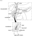
- FIG. 1 is a conceptual diagram illustrating a state in which a bile duct stent according to an embodiment of the present invention is placed.
- FIG. 1 a state in which a bile duct stent 10 according to an embodiment of the present invention is inserted into the bile duct connected to the duodenum is shown.
- the bile duct stent 10 has a cylindrical mesh structure formed using metal wires and has self-elasticity and thus contracts when an external force is applied thereto and expands when the external force is removed.
- the bile duct stent 10 is inserted into a luminal lesion site where a biliary stricture has occurred.
- the bile duct stent 10 expands a lumen by its self-expansile force and maintains the lumen in an expanded state so that the lumen is not narrowed again, and in this way, the bile duct stent 10 serves to facilitate the flow of bile in the duodenum.
- embodiments of the present invention are directed to providing a bile duct stent, in which a backflow-preventing pattern film is formed by weaving a pattern member made of threads (Lasso) or metal wires with a duodenum-side outlet end that is inserted into the bile duct to prevent the backflow of food from the duodenum into the bile duct, and a method of manufacturing the same.
- a backflow-preventing pattern film is formed by weaving a pattern member made of threads (Lasso) or metal wires with a duodenum-side outlet end that is inserted into the bile duct to prevent the backflow of food from the duodenum into the bile duct
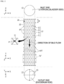
- FIG. 2 illustrates a state in which a bile duct stent is manufactured using a jig according to a first embodiment of the present invention.
- a bile duct stent 10 (hereinafter referred to as "stent" for convenience) according to the first embodiment of the present invention is manufactured by zigzagging metal wires 11 on a plurality of pins P disposed in a circumferential direction X and a longitudinal direction Y of a cylindrical jig 20.
- the stent 10 may be manufactured to have a cylindrical body 12 whose diameter is in a range of 8 mm to 10 mm and a length is in a range of 5 cm to 7 cm, but the stent 10 is not limited thereto and may be made to order by extending the length of the jig 20 according to the size of a lesion site of a patient.
- the metal wires 11 may be made of a shape memory alloy such as nitinol to allow a certain expansile force to act at a certain temperature as in the lumen of the bile duct, but other known stent-manufacturing wires may be utilized as the metal wires 11.
- the metal wires 11 form zigzag patterns by being woven in the circumferential direction X in which the plurality of pins P are disposed at certain intervals, and the stent 10 having the cylindrical body 12 having a mesh structure in which the zigzag patterns formed in the circumferential direction X intersect each other while interfering with each other and are arranged at predetermined intervals W in the longitudinal direction Y is manufactured.
- the cylindrical mesh structure of the stent 10 is shown as having a shape in which rhombic patterns, each with all four sides the same length, are arranged in the circumferential direction X and the longitudinal direction Y of the stent 10.
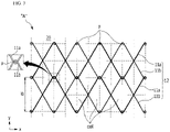
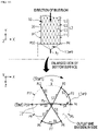
- FIG. 3 is a development view illustrating a weaving structure of a stent body according to the first embodiment of the present invention.
- the metal wires 11 include first metal wires 11a and second metal wires 11b each of which is able to contract and expand by itself, has flexibility, and is formed to have a unit length.
- FIG. 3 a state in which zigzag patterns of the first metal wires 11a and the second metal wires 11b are woven while interfering with each other to form rhombic patterns and are each rotated twice is shown.
- vertical intersection points of a checkerboard shape formed by dotted lines are positions of holes H where the pins P are inserted into the jig 20, and round points at the intersection points indicate a state in which the pins P are installed in the holes H.
- the first metal wires 11a and the second metal wires 11b are woven to manufacture the cylindrical body 12 having the mesh structure.
- first metal wires 11a and the second metal wires 11b are configured to be bent due to the pins P and to only intersect each other without being twisted. In this way, flexibility can be secured, and an easily collapsible structure can be secured upon loading on a catheter afterwards.
- a passage of the cylindrical body 12 is directed according to a direction in which bile flows in the bile duct, and an upper end of the passage that is formed at the liver or gallbladder side is defined as an inlet end (IN) while a lower end of the passage that is formed at the duodenum side is defined as an outlet end (OUT).
- a backflow-preventing pattern film 13 formed of a network structure using nylon threads (Lasso) 15 is formed at the duodenum-side outlet end (OUT) of the cylindrical body 12 that is inserted into the bile duct, and in this way, the backflow of food from the duodenum into the bile duct is prevented.
- the overall process of manufacturing the stent 10 according to the first embodiment of the present invention includes a step in which the metal wires 11 are woven through the jig 20 and then heat-treated to form the cylindrical body 12 having elasticity, a step in which the cylindrical body 12 separated from the jig 20 is fitted to a film jig (not illustrated) and coated with a silicone coating solution and then dried to form a silicone film portion 14, and a step in which the threads 15 are woven to the outlet end of the cylindrical body 12 to manufacture the backflow-preventing pattern film 13 having a network structure.
- FIG. 4 illustrates an example of manufacturing a cross-shaped backflow-preventing pattern film using threads according to the first embodiment of the present invention.
- the stent 10 may be manufactured so that a diameter of the outlet end of the cylindrical body (e.g., 10 mm) is greater than a diameter of the central portion thereof (e.g., 8 mm).
- FIG. 4 shows a state in which the silicone film portion 14 is formed on the cylindrical body 12.
- cells made of the metal wires 11 are arranged in a circular shape about the center like petals of a sunflower.
- a hole h is formed in the silicone film portion 14 of each cell formed at the outlet end of the cylindrical body 12.
- the backflow-preventing pattern film 13 may be formed to have a network structure by repeating a process in which the thread 15 fixed by zigzagging to the cell made of the metal wires 11, which is formed in the circumferential direction through any one hole h at a start point, crosses the outlet end one time or more, and passes through another hole h.
- the thread 15 passes through a first hole h1 from a start point (Start) and then crosses the outlet end and passes through a second hole h2 (S1), passes through a third hole h3 of a cell made of the metal wires 11, which is formed in the circumferential direction, to be woven to another thread 15 so that the threads 15 interfere with each other (S2), passes through a fourth hole h4 and then crosses the outlet end and passes through a fifth hole h5 (S3), then passes through a sixth hole h6, which is formed in the circumferential direction, and then is knotted at an end point (End) (S4).
- the thread 15 may sequentially pass through the holes h of the silicone film portion 14, which is formed on each cell, from the start point (Start) and be woven as if stitched to the cells made of the metal wires 11 to form the cross-shaped backflow-preventing pattern film 13 at the outlet end and then may be knotted at the end point (End) which is the same as the start point (Start).
- the backflow-preventing pattern film 13 according to the first embodiment of the present invention is not limited to the cross-shaped backflow-preventing pattern film 13 described above, and backflow-preventing patterns of various other forms may be applied.
- FIG. 5 illustrates an example of implementing various backflow-preventing pattern films using the threads according to the first embodiment of the present invention.
- backflow-preventing patterns #n since backflow-preventing patterns #n according to various embodiments may be applied to the backflow-preventing pattern film 13 according to the embodiment of the present invention, like "13#n," the reference numeral of the backflow-preventing pattern film 13 and the reference numeral of the backflow-preventing pattern #n will be combined to distinguish the backflow-preventing pattern films 13 having different patterns.
- the backflow-preventing pattern film 13 may be formed as backflow-preventing pattern films 13 having various other patterns such as a straight backflow-preventing pattern film 13#2, a zigzag-shaped backflow-preventing pattern film 13#3, a V-shaped backflow-preventing pattern film 13#3', a polygonal backflow-preventing pattern film 13#4, and a star-shaped backflow-preventing pattern film 13#5 in which the thread 15 is woven between a hole h and another hole h and crosses the outlet end.
- the stent 10 may be manufactured to have various backflow-preventing pattern films 13 according to ways in which the thread 15 is utilized and woven to the outlet end (OUT) of the cylindrical body 12.
- the thread 15 forms a network structure of the backflow-preventing pattern.
- the stent 10 has an effect of preventing the backflow of food from the duodenum into the bile duct.
- the backflow-preventing pattern film 13 may be manufactured by stitching and weaving the thread 15 with a needle passing through the silicone film portion 14 formed on the periphery of the outlet end.
- the stent 10 can be easily loaded on a catheter without difficulty of reducing the diameter of the stent 10, and since, during placement of the stent 10, the stent 10 is unfolded especially to have a pattern simultaneously as the cylindrical body 12 develops at a lesion site of the bile duct, the stent 10 has an effect of preventing the backflow of food from the duodenum into the bile duct.
- the pattern member of the backflow-preventing pattern film 13 of the stent 10 can be manufactured by utilizing the metal wires 11 as well as the threads 15, and a method of manufacturing the backflow-preventing pattern film 13 using the metal wires 11 will be described in detail below according to another embodiment.
- FIG. 6 illustrates a state in which a bile duct stent is manufactured using a jig according to a second embodiment of the present invention.
- a backflow-preventing pattern film 13 using metal wires 11 is formed at the duodenum-side outlet end (OUT) of the cylindrical body 12 that is inserted into the bile duct, and in this way, the backflow of food from the duodenum into the bile duct is prevented.
- the overall process of manufacturing the stent 10 according to the second embodiment of the present invention is different from that according to the first embodiment in that, in a state in which the metal wires 11 are woven through the jig 20 to form the cylindrical body 12, the backflow-preventing pattern film 13 using the metal wires 11 is formed at the outlet end (OUT) and then heat-treated so that the cylindrical body 12 having elasticity and the backflow-preventing pattern film 13 are simultaneously manufactured. Then, the cylindrical body 12 of the stent 10 that is separated from the jig 20 is fitted to a silicone film jig (not illustrated) and coated with a coating solution and then dried to complete the manufacturing process.
- the backflow-preventing pattern film 13 may be formed as the cross-shaped backflow-preventing pattern film 13#1 in which the metal wires 11 are woven between a pin P and another pin P, which are disposed in the circumferential direction X at one end (that is, a lower end) of the jig 20, and cross the outlet end (OUT) and intersect each other.
- pins P1 to P12 disposed in the circumferential direction X at the lower end of the jig 20 are almost collinear with the outlet end at the one end surface.
- the metal wires 11 are knotted by twisting at least once or more after a first line 13a crossing the outlet end from a first pin P1, which is a start point (Start), is woven on a seventh pin P7 and extends and moves 90° to a tenth pin P10 in the circumferential direction X, and then a second line 13b crossing the outlet end (OUT) from the tenth pin P10 vertically intersects the first line 13a and is woven on a fourth pin P4, which is an end point (End).
- the metal wires 11 may be twisted one time or more with the metal wire 11 forming the outlet end when being woven on each pin P and may be fixed to interfere with each other.
- the backflow-preventing pattern film 13 can be easily manufactured. Further, since it is possible to first manufacture the cylindrical body 12 from the inlet end (IN) to the outlet end (OUT) through the jig 20 and then form the backflow-preventing pattern film 13 using the metal wires 11 at the outlet end (OUT) without a pause, there is an advantage in that the manufacturing process is reduced.
- the stent 10 When the task of weaving the metal wires 11 to the backflow-preventing pattern film 13 is completed on the jig 20 as described above, the stent 10 may be separated from the jig 20 and undergo washing and sterilizing processes and then may be shipped out as a finished product.
- a process of coating the cylindrical body 12 with a coating material and forming the film portion 14 may be further performed on the stent 10, and then the stent 10 may be shipped out as a covered-type metal stent product.
- the film portion 14 may be formed by coating the cylindrical body 12 with a coating solution such as polyurethane in a state in which the stent 10 is heated to a certain temperature.
- the backflow-preventing pattern film 13 using the metal wires 11 according to the second embodiment of the present invention is not limited to the cross-shaped backflow-preventing pattern film 13#1 described above, and backflow-preventing patterns of various other forms may be applied.
- FIG. 7 illustrates an example of implementing various backflow-preventing pattern films using metal wires according to the second embodiment of the present invention.
- the backflow-preventing pattern film 13 according to the second embodiment of the present invention is not limited to the cross-shaped backflow-preventing pattern film 13#1 and may also be formed as the zigzag-shaped backflow-preventing pattern film 13#3, the polygonal backflow-preventing pattern film 13#4, and the star-shaped backflow-preventing pattern film 13#5 in which the metal wire 11 is woven between a pin P and another pin P and crosses the outlet end.
- the zigzag-shaped backflow-preventing pattern film 13#3 may be formed by the metal wire 11 being knotted after crossing the outlet end from an eleventh pin P11, which is a start point (Start), and being woven on a third pin P3, and then sequentially crossing the outlet end and being woven on a ninth pin P9, crossing the outlet end and being woven on a fifth pin P5, and crossing the outlet end and being woven on the eleventh pin P 11, which is an end point (End).
- the start point (Start) and the end point (End) are the same.
- a triangular backflow-preventing pattern film may be formed by the metal wire 11 being knotted after crossing the outlet end from the first pin P1, which is a start point (Start), and being woven on the ninth pin P9, and then sequentially crossing the outlet end and being woven on the fifth pin P5, and crossing the outlet end and being woven on the first pin P1, which is an end point (End).
- the polygonal backflow-preventing pattern film 13#4 may be formed in various other polygonal shapes such as a quadrangular shape in addition to being formed in a triangular shape, and the start point (Start) and the end point (End) are the same.
- the star-shaped backflow-preventing pattern film 13#5 may be formed by the metal wire 11 being knotted after crossing the outlet end from the first pin P1, which is the start point (Start), and being woven on an eighth pin P8, and then sequentially crossing the outlet end and being woven on the third pin P3, crossing the outlet end and being woven on the eleventh pin P11, crossing the outlet end and being woven on a sixth pin P6, and crossing the outlet end and being woven on the first pin P1, which is the end point (End).
- the stent 10 may be manufactured to have various backflow-preventing pattern films 13 according to ways in which the jig 20 is utilized and the metal wire 11 is woven to the outlet end (OUT) of the cylindrical body 12. Also, during placement of the stent 10, in a state in which the stent 10 is developed at a lesion site in the bile duct, the stent 10 has an effect of, by the backflow-preventing pattern film 13, preventing the backflow of food from the duodenum into the bile duct.
- the stent 10 may be manufactured to have a denser backflow-preventing pattern film 13 with an increase in the number of lines of the metal wire 11 that connect a pin P and another pin P and cross the outlet end (OUT). This will be described next according to a third embodiment.
- FIG. 8 illustrates a state in which a bile duct stent is manufactured using a jig having a vertical pin formed thereon according to a third embodiment of the present invention.
- the jig 20 includes at least one vertical pin Py formed on a lower surface 21 that corresponds to the outlet end (OUT) of the stent 10.
- the metal wires 11 are sequentially woven between the pins P, which are disposed in the circumferential direction X on the lower end of the jig 20, and the vertical pin Py to form a radial backflow-preventing pattern film 13#6 on the outlet end of the cylindrical body 12.
- the radial backflow-preventing pattern film 13#6 is formed by, in the clockwise direction, the metal wire 11 being woven on the vertical pin Py at the center from a twelfth pin P12 which is a start point (Start) and then being woven on a second pin P2 and extending and moving to the fourth pin P4 in the circumferential direction X (steps S 1, S2, and S3), and then being woven on the vertical pin Py at the center from the fourth pin P4 and then being woven on the sixth pin P6 and extending and moving to the eighth pin P8 in the circumferential direction X (steps S4, S5, and S6), and then being woven on the vertical pin Py at the center from the eighth pin P8 and then being woven on the tenth pin P10 which is an end point (End).
- steps S3 and S5 for extending and moving may be omitted according to changes in the manufacturing method, and a triangular line connecting a pair of pins and the vertical pin Py may be independently formed.
- the metal wires 11 having the three reciprocating lines woven through the vertical pin Py may be fixed by intersecting each other in a bent state.
- the backflow-preventing pattern film 13 may be manufactured to be denser with an increase in the number of lines of the metal wire 11 that cross the outlet end (OUT).
- the backflow-preventing pattern film 13 is not limited to the radial backflow-preventing pattern film 13#6 described above and may be manufactured to have other dense radial backflow-preventing patterns according to various modifications.
- FIG. 9 illustrates various forms of dense radial backflow-preventing pattern films according to the third embodiment of the present invention.
- a first radial backflow-preventing pattern film 13#7 which is denser than the above-described radial backflow-preventing pattern film 13#6 due to an increase in the number of lines of the metal wire 11 woven on the vertical pin Py of the jig 20 of the stent 10 is shown.
- the metal wires 11 are more densely sequentially woven between the pins P, which are disposed in the circumferential direction X on the lower end of the jig 20, and the vertical pin Py to form six reciprocating lines that are woven through the vertical pin Py.
- the six reciprocating lines may be woven with each other and fixed.
- a second radial backflow-preventing pattern film 13#8 is shown which is densely formed by a circular array of vertical pins Py being formed around the center of the lower surface 21 of the jig 20 and the metal wires 11 being woven therethrough.
- the metal wires 11 may be sequentially woven between six pins P, which are disposed in the circumferential direction X at the lower end of the jig 20, and the array of vertical pins Py corresponding thereto to form dense the second radial backflow-preventing pattern film 13#8 on the outlet end of the cylindrical body 12.
- optimal conditions for a bile duct stent in consideration of clinically important physical factors include high flexibility, an excellent radial expansile force, conformability with low axial force to allow the stent to maintain its shape while being bent along the flexion of the bile duct, minimization of a degree of shortening in order to place the stent at a correct position at a lesion site, reduction of a size of a cell between metal wires to reduce growth in a tumor, durability, and a high level of ease of loading the stent on a catheter which is a stent transfer system.
- the ease of loading the stent on a catheter relates to loading the stent 10 in a diameter-reduced state on a catheter to facilitate placement of the stent 10.
- a structure in which it is difficult to physically reduce the diameter of the stent 10 has a disadvantage in that the level of ease of loading is low and a diameter of a catheter is increased, which makes it difficult to insert the catheter into the bile duct and adversely affects the operation carried out by a surgeon.
- the bile duct stent 10 according to the third embodiment of the present invention has a characteristic in that the radial backflow-preventing pattern films 13 of various shapes are formed by the metal wires 11 crossing the outlet end. Since such a characteristic may be disadvantageous for diameter reduction, the level of ease of loading the stent 10 on a catheter may be considered.
- a bile duct stent 10 with a structure in which the level of ease of loading on a catheter is improved will be described next according to a fourth embodiment of the present invention.
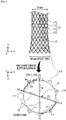
- FIG. 10 illustrates a state in which a bile duct stent is manufactured using a conical jig according to a fourth embodiment of the present invention.
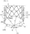
- FIG. 11 is a perspective view illustrating a conical backflow-preventing pattern film according to the fourth embodiment of the present invention.
- the jig 20 according to the fourth embodiment of the present invention includes an outer peripheral surface 22, which is inclined in a conical shape at an outlet end (OUT) of the stent 10, and a vertical pin Py fixed to a vertex of the center of the outer peripheral surface 22.
- a conical backflow-preventing pattern film 13#9 is formed in which the metal wires 11 are sequentially woven between the pins P, which are disposed in the circumferential direction X on the lower end of the jig 20, and the vertical pin Py to form a radial pattern, and the center protrudes due to the outer peripheral surface 22 inclined in the conical shape.
- the process of manufacturing the radial backflow-preventing pattern film 13#6 that has been described above with reference to FIG. 8 may be referenced.
- the conical backflow-preventing pattern film 13#9 may be manufactured to have a denser structure by increasing the number of times the metal wires 11 are woven as in FIG. 9A .
- the lines of the metal wires 11 forming the conical backflow-preventing pattern film 13#9 form a triangular structure as bent portions 11c are formed due to the vertical pin Py and form an inclined structure in which the bent portions 11c intersect and radiate while interfering with each other.
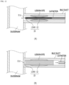
- FIG. 12 illustrates an example in which the stent according to the fourth embodiment of the present invention is placed at a lesion site of the bile duct.
- FIG. 12A shows a state in which the stent 10 according to the embodiment of the present invention is in a diameter-reduced state, loaded on a catheter, and moved past a lesion site in the bile duct.
- the conical backflow-preventing pattern film 13#9 is configured so that, when the stent 10 is loaded in an inner diameter of a catheter for stent placement, a diameter of the cylindrical body 12 is reduced due to an external pressure, and simultaneously, the bent portions 11c are folded without any physical resistance. Thus, there is an effect of facilitating loading of the stent 10 on the catheter.
- FIG. 12B shows a state in which the stent 10 exposed due to the catheter retracting is expanded, causing the lesion site in the bile duct to be expanded.
- the conical backflow-preventing pattern film 13#9 is expanded at a duodenum-side passage of the bile duct to prevent the backflow of food from the duodenum into the bile duct and discharge bile, which flows in the bile duct, to the duodenum.
- FIG. 13 is a perspective view illustrating a truncated conical backflow-preventing pattern film according to the fourth embodiment of the present invention.
- the jig 20 includes a truncated cone outer peripheral surface 23a, which is inclined, and a truncated cone lower surface 23b formed at an outlet end (OUT) of the stent 10 in order to constitute a truncated conical structure which is broad at the top and gets narrower toward the bottom and also includes a circular array of vertical pins Py formed around the center of the truncated cone lower surface 23b.
- a truncated conical backflow-preventing pattern film 13#10 may be formed on the outlet end of the cylindrical body 12.
- the bent portion 11c may be formed due to the vertical pin Py, and the bent portions 11c may radiate and form an inclined structure without interfering with each other.
- backflow-preventing pattern films of various dense patterns can be easily manufactured with a single line of thread or metal wire on an outlet end of the bile duct stent, and by configuring the backflow-preventing pattern films using nylon threads or metal wires, there is an effect of securing durability.
- the embodiments of the present invention are not implemented only through the device and/or method described above and may be implemented through programs for realizing functions corresponding to configurations of the embodiments of the present invention, recording media in which the programs are recorded, etc. Such implementations may be easily carried out by those of ordinary skill in the art to which the present invention pertains from the above description of the embodiments.
Landscapes
- Health & Medical Sciences (AREA)
- Engineering & Computer Science (AREA)
- General Health & Medical Sciences (AREA)
- Heart & Thoracic Surgery (AREA)
- Vascular Medicine (AREA)
- Biomedical Technology (AREA)
- Veterinary Medicine (AREA)
- Public Health (AREA)
- Life Sciences & Earth Sciences (AREA)
- Animal Behavior & Ethology (AREA)
- Transplantation (AREA)
- Oral & Maxillofacial Surgery (AREA)
- Cardiology (AREA)
- Surgery (AREA)
- Epidemiology (AREA)
- Gastroenterology & Hepatology (AREA)
- Pulmonology (AREA)
- Chemical & Material Sciences (AREA)
- Inorganic Chemistry (AREA)
- Mechanical Engineering (AREA)
- Media Introduction/Drainage Providing Device (AREA)
- Prostheses (AREA)
Abstract
Description
- The present invention relates to a bile duct stent and a method of manufacturing the same, and more particularly, to a bile duct stent for preventing the backflow of food in the duodenum and a method of manufacturing the same.
- Generally, a bile duct serves as a passage that allows bile, which is concentrated after being produced by the liver and stored in the gallbladder, to flow to the duodenum. A biliary stricture is a disease in which the bile duct is constricted and the passage is narrowed or blocked due to tumors such as pancreatitis/pancreatic cancer and cholangitis/cholangiocarcinoma.
- A biliary stricture can be treated with surgery, but endoscopic biliary stenting has been used in recent years. In particular, stenting is widely practiced when surgery is not possible due to the onset of a malignant biliary stricture in terminal cancer patients.
- However, regarding the conventional bile duct stent, a problem has been pointed out in that food passing through the duodenum frequently flows back into the bile duct, obstructing the flow of bile and causing side effects due to cholangitis or stent malfunction.
- In order to address such a problem, a bile duct stent having a backflow preventing means has been proposed in the past, but it is difficult to prove its effectiveness due to various shortcomings.
- For example,
Korean Patent Registration No. 0170220 - However, the valves disclosed in
Korean Patent Registration No. 0170220 - Therefore, there is a need for ways to address the conventional backflow prevention problem and secure durability to expand the effects of stent placement in the bile duct.
- Matters described in the "Background Art" section are intended to enhance understanding of the background of the invention and may include matters that are not related art already known to those of ordinary skill in the art to which the present invention pertains.
- Embodiments of the present invention are directed to providing a bile duct stent, in which a backflow-preventing pattern film utilizing a pattern member made of threads (Lasso) or metal wires is formed at a duodenum-side outlet of the stent, which is inserted into the bile duct, to prevent food in the duodenum from flowing back into the bile duct, and a method of manufacturing the same.
- One aspect of the present invention provides a bile duct stent having a backflow preventing means, the bile duct stent including: a cylindrical body having a mesh structure formed by zigzagging metal wires of a shape memory alloy on a plurality of pins each disposed in a circumferential direction (X) and a longitudinal direction (Y) of a cylindrical jig; a film portion coated on cells of the metal wires of the mesh structure; and a backflow-preventing pattern film in which a hole is formed in the film portion of each cell formed at an outlet end of the cylindrical body and threads (Lasso) fixed by zigzagging to the cells of the metal wires in the circumferential direction by passing through any one hole (h) cross the outlet end one time or more to form a network structure.
- Also, another aspect of the present invention provides a bile duct stent having a backflow preventing means, the bile duct stent including: a cylindrical body having a mesh structure formed by zigzagging metal wires of a shape memory alloy on a plurality of pins each disposed in a circumferential direction (X) and a longitudinal direction (Y) of a cylindrical jig; and a backflow-preventing pattern film in which the metal wires are woven on a pin (P) and another pin (P) disposed in the circumferential direction (X) at a lower end of the jig and the metal wires cross an outlet end of the cylindrical body one time or more to form a network structure.
- The backflow-preventing pattern film may be formed as any one of a cross-shaped backflow-preventing pattern film, a straight backflow-preventing pattern film, a zigzag-shaped backflow-preventing pattern film, a polygonal backflow-preventing pattern film, and a star-shaped backflow-preventing pattern film in which the metal wires cross the outlet end and intersect each other.
- Also, the backflow-preventing pattern film may be finished with a twist knot after one line of metal wires is continuously woven from a start-point pin (P) to an end-point pin (P) via at least one pin (P).
- Also, as the cross-shaped backflow-preventing pattern film, one line of metal wires may be knotted by twisting at least once or more after a first line crossing the center of the outlet end from a first pin (P1), which is a start point, is woven on a second pin, extends and moves 90° in the circumferential direction, and is woven on a third pin, and then a second line crossing the outlet end from the third pin vertically intersects the first line and is woven on a fourth pin, which is an end point.
- Also, the backflow-preventing pattern film may be formed as a radial backflow-preventing pattern film by sequentially weaving the metal wires on pins (P) disposed in the circumferential direction (X) at a lower end of the jig and a single vertical pin (Py) disposed at the center of a lower surface of the jig.
- Also, in the radial backflow-preventing pattern film, multiple lines of metal wires woven on the vertical pin (Py) may be fixed by intersecting each other in a bent state.
- Also, the backflow-preventing pattern film may be formed as a conical backflow-preventing pattern film in which an inclined outer peripheral surface having a conical shape is formed at a lower surface of the jig, the vertical pin (Py) is fixed to a vertex at the center of the outer peripheral surface, the metal wires are sequentially woven between the vertical pin (Py) and the pins (P), which are disposed in the circumferential direction (X) at the lower end of the jig, to form a radial pattern, and the center protrudes due to the inclined outer peripheral surface having the conical shape.
- Also, the conical backflow-preventing pattern film may form a triangular structure as bent portions caused by the vertical pin (Py) are formed on the metal wire lines constituting the radial pattern and may form an inclined structure in which the bent portions intersect and radiate while interfering with each other.
- Also, the backflow-preventing pattern film may be formed as a radial backflow-preventing pattern film in which a circular array of vertical pins is formed around the center of the lower surface of the jig, and the pins (P) disposed in the circumferential direction (X) at the lower end and the array of vertical pins (Py) each corresponding to the pins (P) are sequentially woven.
- Also, the backflow-preventing pattern film may be formed as a truncated conical backflow-preventing pattern film in which a truncated cone outer peripheral surface, which is inclined, and a truncated cone lower surface are formed at the lower end of the jig to constitute a shape that is broad at the top and gets narrower toward the bottom, a circular array of the vertical pins (Py) is formed around the center of the truncated cone lower surface, and the pins (P) disposed in the circumferential direction and the array of the vertical pins (Py) each corresponding to the pins (P) are sequentially woven using the metal wires.
- Also, in the truncated conical backflow-preventing pattern film, a bent portion caused by the vertical pin (Py) may be formed on each metal wire line, and the bent portions may form an inclined structure in which the lines radiate without interfering with each other.
- Meanwhile, one aspect of the present invention provides a method of manufacturing a bile duct stent using a jig, the method including: a) forming a cylindrical body having a mesh structure by zigzagging metal wires of a shape memory alloy material on a plurality of pins each disposed in a circumferential direction (X) and a longitudinal direction (Y) of a cylindrical jig; and b) forming a backflow-preventing pattern film having a network structure by causing a pattern member made of threads (Lasso) or metal wires to cross an outlet end of a passage of the cylindrical body one time or more.
- Also, the step b) may include forming a conical backflow-preventing pattern film in which a lower surface of the jig, which has an inclined outer peripheral surface having a conical shape and the vertical pin (Py) fixed to a vertex at the center of the outer peripheral surface, and the pins (P), which are disposed in the circumferential direction (X) at the lower end of the jig, are sequentially woven using the metal wires to form a radial pattern, and the center protrudes due to the inclined outer peripheral surface having the conical shape.
- In addition, the step b) may include: a step in which the metal wire is woven from a first pin (P1), which is a start point, to the vertical pin (Py) at the center to form a bent portion, is woven on a second pin, and then extends and moves to a third pin in a circumferential direction; a step in which the metal wire is woven from the third pin to the vertical pin (Py) at the center to form a bent portion, is woven on a fourth pin, and then extends and moves to a fifth pin in the circumferential direction; and a step in which the metal wire is woven from the fifth pin to the vertical pin (Py) at the center to form a bent portion, is woven on a sixth pin which is an end point, and then is knotted by twisting at least once or more.
- According to embodiments of the present invention, by forming various backflow-preventing pattern films using a pattern member made of threads or metal wires at a duodenum-side outlet end of a cylindrical body of a bile duct stent, there is an effect of preventing the backflow of food into the stent (the bile duct).
- Also, backflow-preventing pattern films of various dense patterns can be easily manufactured with a single line of thread or metal wire on an outlet end of the bile duct stent, and by configuring the backflow-preventing pattern films using nylon threads or metal wires, there is an effect of securing durability.
- In addition, by forming a radial backflow-preventing pattern film, which has a bent portion formed at the center, using metal wires having a self-expansile force, there is an effect of facilitating diameter reduction of the bile duct stent when loading the bile duct stent on a catheter. Further, there is an effect of allowing the backflow preventing performance to be maintained regardless of whether any deformation occurs in the cylindrical body of the stent due to pressure on a lesion site.
-
-
FIG. 1 is a conceptual diagram illustrating a state in which a bile duct stent according to an embodiment of the present invention is placed. -
FIG. 2 illustrates a state in which a bile duct stent is manufactured using a jig according to a first embodiment of the present invention. -
FIG. 3 is a development view illustrating a weaving structure of a stent body according to the first embodiment of the present invention. -
FIG. 4 illustrates an example of manufacturing a cross-shaped backflow-preventing pattern film using threads according to the first embodiment of the present invention. -
FIG. 5 illustrates an example of implementing various backflow-preventing pattern films using the threads according to the first embodiment of the present invention. -
FIG. 6 illustrates a state in which a bile duct stent is manufactured using a jig according to a second embodiment of the present invention. -
FIG. 7 illustrates an example of implementing various backflow-preventing pattern films using metal wires according to the second embodiment of the present invention. -
FIG. 8 illustrates a state in which a bile duct stent is manufactured using a jig having a vertical pin formed thereon according to a third embodiment of the present invention. -
FIG. 9 illustrates various forms of dense radial backflow-preventing pattern films according to the third embodiment of the present invention. -
FIG. 10 illustrates a state in which a bile duct stent is manufactured using a conical jig according to a fourth embodiment of the present invention. -
FIG. 11 is a perspective view illustrating a conical backflow-preventing pattern film according to the fourth embodiment of the present invention. -
FIG. 12 illustrates an example in which the stent according to the fourth embodiment of the present invention is placed at a lesion site of the bile duct. -
FIG. 13 is a perspective view illustrating a truncated conical backflow-preventing pattern film according to the fourth embodiment of the present invention. - Hereinafter, embodiments of the present invention will be described in detail with reference to the accompanying drawings to allow those of ordinary skill in the art to which the present invention pertains to easily carry out the invention. However, the present invention may be implemented in various different forms and is not limited to the embodiments described herein. Also, in the drawings, parts unrelated to the description have been omitted to clearly describe the present invention, and like parts are denoted by like reference numerals throughout the specification.
- Throughout the specification, when a certain part is described as "including" a certain element, unless otherwise stated, this does not exclude the inclusion of other elements but in fact the certain part may further include other elements. Also, terms such as "portion," "-er/or," and "module" indicate units of processing at least one function or operation.
- Throughout the specification, terms such as "first" or "second" may be used to describe various elements, but the elements are not limited by the terms. The terms are only used for the purpose of distinguishing one element from another element. For example, without departing from the scope of rights according to the concept of the present invention, a first element may be referred to as a second element, and likewise, a second element may also be referred to as a first element.
- Now, a bile duct stent and a method of manufacturing the same according to embodiments of the present invention will be described in detail with reference to the drawings.
-
FIG. 1 is a conceptual diagram illustrating a state in which a bile duct stent according to an embodiment of the present invention is placed. - Referring to
FIG. 1 , a state in which abile duct stent 10 according to an embodiment of the present invention is inserted into the bile duct connected to the duodenum is shown. - The
bile duct stent 10 has a cylindrical mesh structure formed using metal wires and has self-elasticity and thus contracts when an external force is applied thereto and expands when the external force is removed. - Through stenting, the
bile duct stent 10 is inserted into a luminal lesion site where a biliary stricture has occurred. Thebile duct stent 10 expands a lumen by its self-expansile force and maintains the lumen in an expanded state so that the lumen is not narrowed again, and in this way, thebile duct stent 10 serves to facilitate the flow of bile in the duodenum. - In the previous description, it has been pointed out that, in the conventional stent structure, food passing through the duodenum may flow back into the expanded bile duct, and when the food flows back into the stent, the flow of bile may be obstructed and various problems may occur.
- Thus, embodiments of the present invention are directed to providing a bile duct stent, in which a backflow-preventing pattern film is formed by weaving a pattern member made of threads (Lasso) or metal wires with a duodenum-side outlet end that is inserted into the bile duct to prevent the backflow of food from the duodenum into the bile duct, and a method of manufacturing the same.
- Hereinafter, in describing the bile duct stent and the method of manufacturing the same according to the present invention, a stent with a backflow-preventing pattern film of various patterns according to the type of the pattern member and a method of manufacturing the same will be described in detail below according to various embodiments.
- First, a stent with a backflow-preventing pattern film using threads and a method of manufacturing the same will be described according to a first embodiment of the present invention.
-
FIG. 2 illustrates a state in which a bile duct stent is manufactured using a jig according to a first embodiment of the present invention. - Referring to
FIG. 2 , a bile duct stent 10 (hereinafter referred to as "stent" for convenience) according to the first embodiment of the present invention is manufactured by zigzaggingmetal wires 11 on a plurality of pins P disposed in a circumferential direction X and a longitudinal direction Y of acylindrical jig 20. - The
stent 10 may be manufactured to have acylindrical body 12 whose diameter is in a range of 8 mm to 10 mm and a length is in a range of 5 cm to 7 cm, but thestent 10 is not limited thereto and may be made to order by extending the length of thejig 20 according to the size of a lesion site of a patient. - The
metal wires 11 may be made of a shape memory alloy such as nitinol to allow a certain expansile force to act at a certain temperature as in the lumen of the bile duct, but other known stent-manufacturing wires may be utilized as themetal wires 11. - The
metal wires 11 form zigzag patterns by being woven in the circumferential direction X in which the plurality of pins P are disposed at certain intervals, and thestent 10 having thecylindrical body 12 having a mesh structure in which the zigzag patterns formed in the circumferential direction X intersect each other while interfering with each other and are arranged at predetermined intervals W in the longitudinal direction Y is manufactured. The cylindrical mesh structure of thestent 10 is shown as having a shape in which rhombic patterns, each with all four sides the same length, are arranged in the circumferential direction X and the longitudinal direction Y of thestent 10. - For example,
FIG. 3 is a development view illustrating a weaving structure of a stent body according to the first embodiment of the present invention. - The
metal wires 11 according to the embodiment of the present invention includefirst metal wires 11a andsecond metal wires 11b each of which is able to contract and expand by itself, has flexibility, and is formed to have a unit length. - Referring to
FIG. 3 , a state in which zigzag patterns of thefirst metal wires 11a and thesecond metal wires 11b are woven while interfering with each other to form rhombic patterns and are each rotated twice is shown. - Here, vertical intersection points of a checkerboard shape formed by dotted lines are positions of holes H where the pins P are inserted into the
jig 20, and round points at the intersection points indicate a state in which the pins P are installed in the holes H. In the state in which the pins P are disposed in thejig 20, thefirst metal wires 11a and thesecond metal wires 11b are woven to manufacture thecylindrical body 12 having the mesh structure. - Also, the
first metal wires 11a and thesecond metal wires 11b are configured to be bent due to the pins P and to only intersect each other without being twisted. In this way, flexibility can be secured, and an easily collapsible structure can be secured upon loading on a catheter afterwards. - A passage of the
cylindrical body 12 is directed according to a direction in which bile flows in the bile duct, and an upper end of the passage that is formed at the liver or gallbladder side is defined as an inlet end (IN) while a lower end of the passage that is formed at the duodenum side is defined as an outlet end (OUT). - Here, in the
stent 10 according to the first embodiment of the present invention, a backflow-preventingpattern film 13 formed of a network structure using nylon threads (Lasso) 15 is formed at the duodenum-side outlet end (OUT) of thecylindrical body 12 that is inserted into the bile duct, and in this way, the backflow of food from the duodenum into the bile duct is prevented. - The overall process of manufacturing the
stent 10 according to the first embodiment of the present invention includes a step in which themetal wires 11 are woven through thejig 20 and then heat-treated to form thecylindrical body 12 having elasticity, a step in which thecylindrical body 12 separated from thejig 20 is fitted to a film jig (not illustrated) and coated with a silicone coating solution and then dried to form asilicone film portion 14, and a step in which thethreads 15 are woven to the outlet end of thecylindrical body 12 to manufacture the backflow-preventingpattern film 13 having a network structure. - For example,
FIG. 4 illustrates an example of manufacturing a cross-shaped backflow-preventing pattern film using threads according to the first embodiment of the present invention. - Referring to
FIG. 4 , thestent 10 according to the first embodiment of the present invention may be manufactured so that a diameter of the outlet end of the cylindrical body (e.g., 10 mm) is greater than a diameter of the central portion thereof (e.g., 8 mm).FIG. 4 shows a state in which thesilicone film portion 14 is formed on thecylindrical body 12. Here, from an enlarged view of the bottom surface of the outlet end of thecylindrical body 12, it can be seen that cells made of themetal wires 11 are arranged in a circular shape about the center like petals of a sunflower. - Here, a hole h is formed in the
silicone film portion 14 of each cell formed at the outlet end of thecylindrical body 12. - The backflow-preventing
pattern film 13 may be formed to have a network structure by repeating a process in which thethread 15 fixed by zigzagging to the cell made of themetal wires 11, which is formed in the circumferential direction through any one hole h at a start point, crosses the outlet end one time or more, and passes through another hole h. - For example, looking at the process of manufacturing the cross-shaped backflow-preventing
pattern film 13 in detail with reference toFIG. 4 , thethread 15 passes through a first hole h1 from a start point (Start) and then crosses the outlet end and passes through a second hole h2 (S1), passes through a third hole h3 of a cell made of themetal wires 11, which is formed in the circumferential direction, to be woven to anotherthread 15 so that thethreads 15 interfere with each other (S2), passes through a fourth hole h4 and then crosses the outlet end and passes through a fifth hole h5 (S3), then passes through a sixth hole h6, which is formed in the circumferential direction, and then is knotted at an end point (End) (S4). - In this way, with one task, the
thread 15 may sequentially pass through the holes h of thesilicone film portion 14, which is formed on each cell, from the start point (Start) and be woven as if stitched to the cells made of themetal wires 11 to form the cross-shaped backflow-preventingpattern film 13 at the outlet end and then may be knotted at the end point (End) which is the same as the start point (Start). - Meanwhile, the backflow-preventing
pattern film 13 according to the first embodiment of the present invention is not limited to the cross-shaped backflow-preventingpattern film 13 described above, and backflow-preventing patterns of various other forms may be applied. - For example,
FIG. 5 illustrates an example of implementing various backflow-preventing pattern films using the threads according to the first embodiment of the present invention. - Referring to
FIG. 5 , hereinafter, since backflow-preventing patterns #n according to various embodiments may be applied to the backflow-preventingpattern film 13 according to the embodiment of the present invention, like "13#n," the reference numeral of the backflow-preventingpattern film 13 and the reference numeral of the backflow-preventing pattern #n will be combined to distinguish the backflow-preventingpattern films 13 having different patterns. - That is, in addition to the above-described cross-shaped backflow-preventing
pattern film 13#1, the backflow-preventingpattern film 13 may be formed as backflow-preventingpattern films 13 having various other patterns such as a straight backflow-preventingpattern film 13#2, a zigzag-shaped backflow-preventingpattern film 13#3, a V-shaped backflow-preventingpattern film 13#3', a polygonal backflow-preventingpattern film 13#4, and a star-shaped backflow-preventingpattern film 13#5 in which thethread 15 is woven between a hole h and another hole h and crosses the outlet end. - In this way, the
stent 10 according to an embodiment of the present invention may be manufactured to have various backflow-preventingpattern films 13 according to ways in which thethread 15 is utilized and woven to the outlet end (OUT) of thecylindrical body 12. During placement of thestent 10, in a state in which thestent 10 is developed at a lesion site in the bile duct, thethread 15 forms a network structure of the backflow-preventing pattern. In this way, thestent 10 has an effect of preventing the backflow of food from the duodenum into the bile duct. - Also, the backflow-preventing
pattern film 13 may be manufactured by stitching and weaving thethread 15 with a needle passing through thesilicone film portion 14 formed on the periphery of the outlet end. - Since the backflow-preventing
pattern film 13 is manufactured using threads, thestent 10 can be easily loaded on a catheter without difficulty of reducing the diameter of thestent 10, and since, during placement of thestent 10, thestent 10 is unfolded especially to have a pattern simultaneously as thecylindrical body 12 develops at a lesion site of the bile duct, thestent 10 has an effect of preventing the backflow of food from the duodenum into the bile duct. - Meanwhile, the pattern member of the backflow-preventing
pattern film 13 of thestent 10 according to the embodiment of the present invention can be manufactured by utilizing themetal wires 11 as well as thethreads 15, and a method of manufacturing the backflow-preventingpattern film 13 using themetal wires 11 will be described in detail below according to another embodiment. -
FIG. 6 illustrates a state in which a bile duct stent is manufactured using a jig according to a second embodiment of the present invention. - Hereinafter, since structures of a
jig 20 and astent 10 manufactured according thereto according to the second embodiment of the present invention are similar to those in the first embodiment described above, overlapping description will be omitted, and differences from the first embodiment will be mainly described. - Referring to
FIG. 6 , in thestent 10 according to the second embodiment of the present invention, a backflow-preventingpattern film 13 usingmetal wires 11 is formed at the duodenum-side outlet end (OUT) of thecylindrical body 12 that is inserted into the bile duct, and in this way, the backflow of food from the duodenum into the bile duct is prevented. - The overall process of manufacturing the
stent 10 according to the second embodiment of the present invention is different from that according to the first embodiment in that, in a state in which themetal wires 11 are woven through thejig 20 to form thecylindrical body 12, the backflow-preventingpattern film 13 using themetal wires 11 is formed at the outlet end (OUT) and then heat-treated so that thecylindrical body 12 having elasticity and the backflow-preventingpattern film 13 are simultaneously manufactured. Then, thecylindrical body 12 of thestent 10 that is separated from thejig 20 is fitted to a silicone film jig (not illustrated) and coated with a coating solution and then dried to complete the manufacturing process. - The backflow-preventing
pattern film 13 may be formed as the cross-shaped backflow-preventingpattern film 13#1 in which themetal wires 11 are woven between a pin P and another pin P, which are disposed in the circumferential direction X at one end (that is, a lower end) of thejig 20, and cross the outlet end (OUT) and intersect each other. Here, pins P1 to P12 disposed in the circumferential direction X at the lower end of thejig 20 are almost collinear with the outlet end at the one end surface. - Specifically, in order to form the cross-shaped backflow-preventing
pattern film 13#1, themetal wires 11 are knotted by twisting at least once or more after afirst line 13a crossing the outlet end from a first pin P1, which is a start point (Start), is woven on a seventh pin P7 and extends and moves 90° to a tenth pin P10 in the circumferential direction X, and then asecond line 13b crossing the outlet end (OUT) from the tenth pin P10 vertically intersects thefirst line 13a and is woven on a fourth pin P4, which is an end point (End). In the above process, themetal wires 11 may be twisted one time or more with themetal wire 11 forming the outlet end when being woven on each pin P and may be fixed to interfere with each other. - In this way, by one line of the
metal wires 11 being continuously woven from the first pin P1, which is the start point (Start), to the fourth pin P4, which is the end point (End), and then being finished with a twist knot to another line, the backflow-preventingpattern film 13 can be easily manufactured. Further, since it is possible to first manufacture thecylindrical body 12 from the inlet end (IN) to the outlet end (OUT) through thejig 20 and then form the backflow-preventingpattern film 13 using themetal wires 11 at the outlet end (OUT) without a pause, there is an advantage in that the manufacturing process is reduced. - When the task of weaving the
metal wires 11 to the backflow-preventingpattern film 13 is completed on thejig 20 as described above, thestent 10 may be separated from thejig 20 and undergo washing and sterilizing processes and then may be shipped out as a finished product. Here, a process of coating thecylindrical body 12 with a coating material and forming thefilm portion 14 may be further performed on thestent 10, and then thestent 10 may be shipped out as a covered-type metal stent product. Thefilm portion 14 may be formed by coating thecylindrical body 12 with a coating solution such as polyurethane in a state in which thestent 10 is heated to a certain temperature. - Meanwhile, the backflow-preventing
pattern film 13 using themetal wires 11 according to the second embodiment of the present invention is not limited to the cross-shaped backflow-preventingpattern film 13#1 described above, and backflow-preventing patterns of various other forms may be applied. - For example,
FIG. 7 illustrates an example of implementing various backflow-preventing pattern films using metal wires according to the second embodiment of the present invention. - Referring to
FIG. 7 , the backflow-preventingpattern film 13 according to the second embodiment of the present invention is not limited to the cross-shaped backflow-preventingpattern film 13#1 and may also be formed as the zigzag-shaped backflow-preventingpattern film 13#3, the polygonal backflow-preventingpattern film 13#4, and the star-shaped backflow-preventingpattern film 13#5 in which themetal wire 11 is woven between a pin P and another pin P and crosses the outlet end. - Referring to
FIG. 7A , the zigzag-shaped backflow-preventingpattern film 13#3 may be formed by themetal wire 11 being knotted after crossing the outlet end from an eleventh pin P11, which is a start point (Start), and being woven on a third pin P3, and then sequentially crossing the outlet end and being woven on a ninth pin P9, crossing the outlet end and being woven on a fifth pin P5, and crossing the outlet end and being woven on theeleventh pin P 11, which is an end point (End). The start point (Start) and the end point (End) are the same. - Referring to
FIG. 7B , a triangular backflow-preventing pattern film may be formed by themetal wire 11 being knotted after crossing the outlet end from the first pin P1, which is a start point (Start), and being woven on the ninth pin P9, and then sequentially crossing the outlet end and being woven on the fifth pin P5, and crossing the outlet end and being woven on the first pin P1, which is an end point (End). Here, the polygonal backflow-preventingpattern film 13#4 may be formed in various other polygonal shapes such as a quadrangular shape in addition to being formed in a triangular shape, and the start point (Start) and the end point (End) are the same. - Referring to
FIG. 7C , the star-shaped backflow-preventingpattern film 13#5 may be formed by themetal wire 11 being knotted after crossing the outlet end from the first pin P1, which is the start point (Start), and being woven on an eighth pin P8, and then sequentially crossing the outlet end and being woven on the third pin P3, crossing the outlet end and being woven on the eleventh pin P11, crossing the outlet end and being woven on a sixth pin P6, and crossing the outlet end and being woven on the first pin P1, which is the end point (End). - In addition, the
stent 10 according to the embodiment of the present invention may be manufactured to have various backflow-preventingpattern films 13 according to ways in which thejig 20 is utilized and themetal wire 11 is woven to the outlet end (OUT) of thecylindrical body 12. Also, during placement of thestent 10, in a state in which thestent 10 is developed at a lesion site in the bile duct, thestent 10 has an effect of, by the backflow-preventingpattern film 13, preventing the backflow of food from the duodenum into the bile duct. - Meanwhile, the
stent 10 may be manufactured to have a denser backflow-preventingpattern film 13 with an increase in the number of lines of themetal wire 11 that connect a pin P and another pin P and cross the outlet end (OUT). This will be described next according to a third embodiment. -
FIG. 8 illustrates a state in which a bile duct stent is manufactured using a jig having a vertical pin formed thereon according to a third embodiment of the present invention. - Hereinafter, since structures of a
jig 20 and astent 10 manufactured according thereto according to the third embodiment of the present invention are similar to those in the second embodiment described above, overlapping description will be omitted, and differences from the second embodiment will be mainly described. - Referring to
FIG. 8 , thejig 20 according to the third embodiment of the present invention includes at least one vertical pin Py formed on a lower surface 21 that corresponds to the outlet end (OUT) of thestent 10. - In the
stent 10, themetal wires 11 are sequentially woven between the pins P, which are disposed in the circumferential direction X on the lower end of thejig 20, and the vertical pin Py to form a radial backflow-preventingpattern film 13#6 on the outlet end of thecylindrical body 12. - As a specific example, the radial backflow-preventing
pattern film 13#6 is formed by, in the clockwise direction, themetal wire 11 being woven on the vertical pin Py at the center from a twelfth pin P12 which is a start point (Start) and then being woven on a second pin P2 and extending and moving to the fourth pin P4 in the circumferential direction X (stepsS 1, S2, and S3), and then being woven on the vertical pin Py at the center from the fourth pin P4 and then being woven on the sixth pin P6 and extending and moving to the eighth pin P8 in the circumferential direction X (steps S4, S5, and S6), and then being woven on the vertical pin Py at the center from the eighth pin P8 and then being woven on the tenth pin P10 which is an end point (End). Here, the steps S3 and S5 for extending and moving may be omitted according to changes in the manufacturing method, and a triangular line connecting a pair of pins and the vertical pin Py may be independently formed. Here, themetal wires 11 having the three reciprocating lines woven through the vertical pin Py may be fixed by intersecting each other in a bent state. - Meanwhile, the backflow-preventing
pattern film 13 may be manufactured to be denser with an increase in the number of lines of themetal wire 11 that cross the outlet end (OUT). Thus, the backflow-preventingpattern film 13 is not limited to the radial backflow-preventingpattern film 13#6 described above and may be manufactured to have other dense radial backflow-preventing patterns according to various modifications. - For example,
FIG. 9 illustrates various forms of dense radial backflow-preventing pattern films according to the third embodiment of the present invention. - First, referring to
FIG. 9A , a first radial backflow-preventingpattern film 13#7 which is denser than the above-described radial backflow-preventingpattern film 13#6 due to an increase in the number of lines of themetal wire 11 woven on the vertical pin Py of thejig 20 of thestent 10 is shown. - Here, in the first radial backflow-preventing
pattern film 13#7, themetal wires 11 are more densely sequentially woven between the pins P, which are disposed in the circumferential direction X on the lower end of thejig 20, and the vertical pin Py to form six reciprocating lines that are woven through the vertical pin Py. The six reciprocating lines may be woven with each other and fixed. - Next, referring to
FIG. 9B , as a modification of the first dense radial backflow-preventingpattern film 13#7, a second radial backflow-preventingpattern film 13#8 is shown which is densely formed by a circular array of vertical pins Py being formed around the center of the lower surface 21 of thejig 20 and themetal wires 11 being woven therethrough. - That is, the
metal wires 11 may be sequentially woven between six pins P, which are disposed in the circumferential direction X at the lower end of thejig 20, and the array of vertical pins Py corresponding thereto to form dense the second radial backflow-preventingpattern film 13#8 on the outlet end of thecylindrical body 12. - In this way, according to the third embodiment of the present invention, by utilizing at least one vertical pin Py formed on the lower surface 21 of the
jig 20, there is an effect of allowing a radial pattern film, in which lines are denser and disposed at more uniform intervals as compared to the first and second embodiments, to be formed on the outlet end of thestent 10. - Meanwhile, optimal conditions for a bile duct stent in consideration of clinically important physical factors include high flexibility, an excellent radial expansile force, conformability with low axial force to allow the stent to maintain its shape while being bent along the flexion of the bile duct, minimization of a degree of shortening in order to place the stent at a correct position at a lesion site, reduction of a size of a cell between metal wires to reduce growth in a tumor, durability, and a high level of ease of loading the stent on a catheter which is a stent transfer system.
- Among the above conditions, the ease of loading the stent on a catheter relates to loading the
stent 10 in a diameter-reduced state on a catheter to facilitate placement of thestent 10. A structure in which it is difficult to physically reduce the diameter of thestent 10 has a disadvantage in that the level of ease of loading is low and a diameter of a catheter is increased, which makes it difficult to insert the catheter into the bile duct and adversely affects the operation carried out by a surgeon. - Here, the
bile duct stent 10 according to the third embodiment of the present invention has a characteristic in that the radial backflow-preventingpattern films 13 of various shapes are formed by themetal wires 11 crossing the outlet end. Since such a characteristic may be disadvantageous for diameter reduction, the level of ease of loading thestent 10 on a catheter may be considered. - Thus, a
bile duct stent 10 with a structure in which the level of ease of loading on a catheter is improved will be described next according to a fourth embodiment of the present invention. -
FIG. 10 illustrates a state in which a bile duct stent is manufactured using a conical jig according to a fourth embodiment of the present invention. -
FIG. 11 is a perspective view illustrating a conical backflow-preventing pattern film according to the fourth embodiment of the present invention. - Hereinafter, since structures of a
jig 20 and astent 10 manufactured according thereto according to the fourth embodiment of the present invention are similar to those in the third embodiment described above, overlapping description will be omitted, and the structure in which the level of ease of loading on a catheter is improved will be mainly described. - Referring to
FIGS. 10 and11 , thejig 20 according to the fourth embodiment of the present invention includes an outerperipheral surface 22, which is inclined in a conical shape at an outlet end (OUT) of thestent 10, and a vertical pin Py fixed to a vertex of the center of the outerperipheral surface 22. - Also, in the
stent 10, a conical backflow-preventingpattern film 13#9 is formed in which themetal wires 11 are sequentially woven between the pins P, which are disposed in the circumferential direction X on the lower end of thejig 20, and the vertical pin Py to form a radial pattern, and the center protrudes due to the outerperipheral surface 22 inclined in the conical shape. For a specific method of weaving themetal wires 11 to form the conical backflow-preventingpattern film 13#9, the process of manufacturing the radial backflow-preventingpattern film 13#6 that has been described above with reference toFIG. 8 may be referenced. Further, the conical backflow-preventingpattern film 13#9 may be manufactured to have a denser structure by increasing the number of times themetal wires 11 are woven as inFIG. 9A . - Here, the lines of the
metal wires 11 forming the conical backflow-preventingpattern film 13#9 form a triangular structure asbent portions 11c are formed due to the vertical pin Py and form an inclined structure in which thebent portions 11c intersect and radiate while interfering with each other. - Meanwhile,
FIG. 12 illustrates an example in which the stent according to the fourth embodiment of the present invention is placed at a lesion site of the bile duct. -
FIG. 12A shows a state in which thestent 10 according to the embodiment of the present invention is in a diameter-reduced state, loaded on a catheter, and moved past a lesion site in the bile duct. - Here, the conical backflow-preventing
pattern film 13#9 is configured so that, when thestent 10 is loaded in an inner diameter of a catheter for stent placement, a diameter of thecylindrical body 12 is reduced due to an external pressure, and simultaneously, thebent portions 11c are folded without any physical resistance. Thus, there is an effect of facilitating loading of thestent 10 on the catheter. - Also,
FIG. 12B shows a state in which thestent 10 exposed due to the catheter retracting is expanded, causing the lesion site in the bile duct to be expanded. - Here, the conical backflow-preventing
pattern film 13#9 is expanded at a duodenum-side passage of the bile duct to prevent the backflow of food from the duodenum into the bile duct and discharge bile, which flows in the bile duct, to the duodenum. - Meanwhile,
FIG. 13 is a perspective view illustrating a truncated conical backflow-preventing pattern film according to the fourth embodiment of the present invention. - Referring to
FIG. 13 , thejig 20 according to the fourth embodiment of the present invention includes a truncated cone outerperipheral surface 23a, which is inclined, and a truncated conelower surface 23b formed at an outlet end (OUT) of thestent 10 in order to constitute a truncated conical structure which is broad at the top and gets narrower toward the bottom and also includes a circular array of vertical pins Py formed around the center of the truncated conelower surface 23b. - Here, in the
stent 10, by themetal wires 11 being sequentially woven between the pins P, which are disposed in the circumferential direction X at the lower end of thejig 20, and the array of vertical pins Py which correspond to the pins P and are arranged in a circular shape on the truncated conelower surface 23b, a truncated conical backflow-preventingpattern film 13#10 may be formed on the outlet end of thecylindrical body 12. - Here, in each of the lines of the
metal wires 11 constituting the truncated conical backflow-preventingpattern film 13#10, thebent portion 11c may be formed due to the vertical pin Py, and thebent portions 11c may radiate and form an inclined structure without interfering with each other. - In this way, according to the embodiments of the present invention, by forming various backflow-preventing pattern films using a pattern member made of threads or metal wires at a duodenum-side outlet end of a cylindrical body of a bile duct stent, there is an effect of preventing the backflow of food into the stent (the bile duct).
- Also, backflow-preventing pattern films of various dense patterns can be easily manufactured with a single line of thread or metal wire on an outlet end of the bile duct stent, and by configuring the backflow-preventing pattern films using nylon threads or metal wires, there is an effect of securing durability.
- In addition, by forming a radial backflow-preventing pattern film, which has a bent portion formed at the center, using metal wires having a self-expansile force, there is an effect of facilitating diameter reduction of the bile duct stent when loading the bile duct stent on a catheter. Further, there is an effect of allowing the backflow preventing performance to be maintained regardless of whether any deformation occurs in the cylindrical body of the stent due to a pressure in a lesion site.
- The embodiments of the present invention are not implemented only through the device and/or method described above and may be implemented through programs for realizing functions corresponding to configurations of the embodiments of the present invention, recording media in which the programs are recorded, etc. Such implementations may be easily carried out by those of ordinary skill in the art to which the present invention pertains from the above description of the embodiments.
- The embodiments of the present invention have been described in detail above, but the scope of rights of the present invention is not limited thereto, and various modifications and improvements made by those of ordinary skill in the art using the basic concept of the present invention defined in the attached claims also fall within the scope of rights of the present invention.
Claims (15)
- A bile duct stent comprising:a cylindrical body having a mesh structure formed by zigzagging metal wires of a shape memory alloy on a plurality of pins each disposed in a circumferential direction (X) and a longitudinal direction (Y) of a cylindrical jig;a film portion coated on cells of the metal wires of the mesh structure; anda backflow-preventing pattern film in which a hole is formed in the film portion of each cell formed at an outlet end of the cylindrical body and threads (Lasso) fixed by zigzagging to the cells of the metal wires in the circumferential direction by passing through any one hole (h) cross the outlet end one time or more to form a network structure.
- A bile duct stent comprising:a cylindrical body having a mesh structure formed by zigzagging metal wires of a shape memory alloy on a plurality of pins each disposed in a circumferential direction (X) and a longitudinal direction (Y) of a cylindrical jig; anda backflow-preventing pattern film in which the metal wires are woven on a pin (P) and another pin (P) disposed in the circumferential direction (X) at a lower end of the jig and the metal wires cross an outlet end of the cylindrical body one time or more to form a network structure.
- The bile duct stent of claim 1 or 2, wherein the backflow-preventing pattern film is formed as any one of a cross-shaped backflow-preventing pattern film, a straight backflow-preventing pattern film, a zigzag-shaped backflow-preventing pattern film, a polygonal backflow-preventing pattern film, and a star-shaped backflow-preventing pattern film in which the metal wires cross the outlet end and intersect each other.
- The bile duct stent of claim 2, wherein the backflow-preventing pattern film is finished with a twist knot after one line of metal wires is continuously woven from a start-point pin (P) to an end-point pin (P) via at least one pin (P).
- The bile duct stent of claim 3, wherein, as the cross-shaped backflow-preventing pattern film, one line of metal wires is knotted by twisting at least once or more after a first line crossing the center of the outlet end from a first pin (P1), which is a start point, is woven on a second pin, extends and moves 90° in the circumferential direction, and is woven on a third pin, and then a second line crossing the outlet end from the third pin vertically intersects the first line and is woven on a fourth pin, which is an end point.
- The bile duct stent of claim 2, wherein the backflow-preventing pattern film is formed as a radial backflow-preventing pattern film by sequentially weaving the metal wires on pins (P) disposed in the circumferential direction (X) at a lower end of the jig and a single vertical pin (Py) disposed at the center of a lower surface of the jig.
- The bile duct stent of claim 6, wherein, in the radial backflow-preventing pattern film, multiple lines of metal wires woven on the vertical pin (Py) are fixed by intersecting each other in a bent state.
- The bile duct stent of claim 1, wherein the backflow-preventing pattern film is formed as a conical backflow-preventing pattern film in which an inclined outer peripheral surface having a conical shape is formed at a lower surface of the jig, the vertical pin (Py) is fixed to a vertex at the center of the outer peripheral surface, the metal wires are sequentially woven between the vertical pin (Py) and the pins (P), which are disposed in the circumferential direction (X) at the lower end of the jig, to form a radial pattern, and the center protrudes due to the inclined outer peripheral surface having the conical shape.
- The bile duct stent of claim 8, wherein the conical backflow-preventing pattern film forms a triangular structure as bent portions caused by the vertical pin (Py) are formed on the metal wire lines constituting the radial pattern and forms an inclined structure in which the bent portions intersect and radiate while interfering with each other.
- The bile duct stent of claim 1, wherein the backflow-preventing pattern film is formed as a radial backflow-preventing pattern film in which a circular array of vertical pins is formed around the center of the lower surface of the jig, and the pins (P) disposed in the circumferential direction (X) at the lower end and the array of vertical pins (Py) each corresponding to the pins (P) are sequentially woven.
- The bile duct stent of claim 1, wherein the backflow-preventing pattern film is formed as a truncated conical backflow-preventing pattern film in which a truncated cone outer peripheral surface, which is inclined, and a truncated cone lower surface are formed at the lower end of the jig to constitute a shape that is broad at the top and gets narrower toward the bottom, a circular array of the vertical pins (Py) is formed around the center of the truncated cone lower surface, and the pins (P) disposed in the circumferential direction and the array of the vertical pins (Py) each corresponding to the pins (P) are sequentially woven using the metal wires.
- The bile duct stent of claim 11, wherein, in the truncated conical backflow-preventing pattern film, a bent portion caused by the vertical pin (Py) is formed on each metal wire line, and the bent portions form an inclined structure in which the lines radiate without interfering with each other.
- A method of manufacturing a bile duct stent using a jig, the method comprising:a) forming a cylindrical body having a mesh structure by zigzagging metal wires of a shape memory alloy material on a plurality of pins each disposed in a circumferential direction (X) and a longitudinal direction (Y) of a cylindrical jig; andb) forming a backflow-preventing pattern film having a network structure by causing a pattern member made of threads (Lasso) or metal wires to cross an outlet end of a passage of the cylindrical body one time or more.
- The method of claim 13, wherein the step b) includes forming a conical backflow-preventing pattern film in which a lower surface of the jig, which has an inclined outer peripheral surface having a conical shape and the vertical pin (Py) fixed to a vertex at the center of the outer peripheral surface, and the pins (P), which are disposed in the circumferential direction (X) at the lower end of the jig, are sequentially woven using the metal wires to form a radial pattern, and the center protrudes due to the inclined outer peripheral surface having the conical shape.
- The method of claim 13 or 14, wherein the step b) includes:a step in which the metal wire is woven from a first pin (P1), which is a start point, to the vertical pin (Py) at the center to form a bent portion, is woven on a second pin, and then extends and moves to a third pin in a circumferential direction;a step in which the metal wire is woven from the third pin to the vertical pin (Py) at the center to form a bent portion, is woven on a fourth pin, and then extends and moves to a fifth pin in the circumferential direction; anda step in which the metal wire is woven from the fifth pin to the vertical pin (Py) at the center to form a bent portion, is woven on a sixth pin which is an end point, and then is knotted by twisting at least once or more.
Applications Claiming Priority (2)
| Application Number | Priority Date | Filing Date | Title |
|---|---|---|---|
| KR1020200046815A KR102409245B1 (en) | 2020-04-17 | 2020-04-17 | Stent for bile duct and method of manufacture the same |
| PCT/KR2021/004125 WO2021210821A1 (en) | 2020-04-17 | 2021-04-02 | Bile duct stent and manufacturing method thereof |
Publications (2)
| Publication Number | Publication Date |
|---|---|
| EP4137101A1 true EP4137101A1 (en) | 2023-02-22 |
| EP4137101A4 EP4137101A4 (en) | 2023-09-13 |
Family
ID=78085030
Family Applications (1)
| Application Number | Title | Priority Date | Filing Date |
|---|---|---|---|
| EP21788864.3A Pending EP4137101A4 (en) | 2020-04-17 | 2021-04-02 | Bile duct stent and manufacturing method thereof |
Country Status (6)
| Country | Link |
|---|---|
| US (1) | US20220304796A1 (en) |
| EP (1) | EP4137101A4 (en) |
| JP (1) | JP7385043B2 (en) |
| KR (1) | KR102409245B1 (en) |
| CN (1) | CN114901220A (en) |
| WO (1) | WO2021210821A1 (en) |
Families Citing this family (2)
| Publication number | Priority date | Publication date | Assignee | Title |
|---|---|---|---|---|
| CN115553972B (en) * | 2022-10-19 | 2023-10-20 | 常州乐奥医疗科技股份有限公司 | Biliary tract stent manufacturing method and biliary tract stent |
| CN116350411A (en) * | 2023-04-11 | 2023-06-30 | 江苏唯德康医疗科技有限公司 | Support braiding method and support braided by using same |
Family Cites Families (8)
| Publication number | Priority date | Publication date | Assignee | Title |
|---|---|---|---|---|
| KR0170220B1 (en) | 1996-08-31 | 1999-03-20 | 김광호 | Stent having means preventing counter-current flow |
| US6790237B2 (en) * | 2001-10-09 | 2004-09-14 | Scimed Life Systems, Inc. | Medical stent with a valve and related methods of manufacturing |
| KR100442330B1 (en) * | 2002-09-03 | 2004-07-30 | 주식회사 엠아이텍 | Stent and manufacturing method the same |
| KR101006972B1 (en) | 2009-02-19 | 2011-01-12 | 신경민 | The stent that food counter current prevention and internal decomposition are possible |
| EP2361594A4 (en) * | 2009-07-10 | 2014-11-05 | Taewoong Medical Co Ltd | Stent |
| US9226812B2 (en) * | 2012-01-30 | 2016-01-05 | Kawasumi Laboratories, Inc. | Biliary stent |
| KR20140094144A (en) * | 2013-01-21 | 2014-07-30 | 주식회사 엠아이텍 | Stent for preventing migration and apparatus and method thereof |
| KR101996524B1 (en) * | 2017-08-02 | 2019-07-04 | (주)태웅메디칼 | A stent for biliary tract |
-
2020
- 2020-04-17 KR KR1020200046815A patent/KR102409245B1/en active IP Right Grant
-
2021
- 2021-04-02 WO PCT/KR2021/004125 patent/WO2021210821A1/en unknown
- 2021-04-02 EP EP21788864.3A patent/EP4137101A4/en active Pending
- 2021-04-02 CN CN202180007500.6A patent/CN114901220A/en active Pending
- 2021-04-02 JP JP2022537361A patent/JP7385043B2/en active Active
-
2022
- 2022-06-15 US US17/840,626 patent/US20220304796A1/en active Pending
Also Published As
| Publication number | Publication date |
|---|---|
| CN114901220A (en) | 2022-08-12 |
| JP2023508863A (en) | 2023-03-06 |
| WO2021210821A1 (en) | 2021-10-21 |
| KR102409245B1 (en) | 2022-06-15 |
| JP7385043B2 (en) | 2023-11-21 |
| KR20210128756A (en) | 2021-10-27 |
| EP4137101A4 (en) | 2023-09-13 |
| US20220304796A1 (en) | 2022-09-29 |
Similar Documents
| Publication | Publication Date | Title |
|---|---|---|
| US20220304796A1 (en) | Bile duct stent and method of manufacturing the same | |
| JP4669699B2 (en) | Reticulated stent and manufacturing method thereof | |
| RU2452432C2 (en) | Implantable device | |
| EP2344069B1 (en) | Implantable prosthesis with reduced density regions | |
| JP7075660B2 (en) | Stent | |
| US10058440B2 (en) | Carotid stent apparatus and methods for treatment via body lumens | |
| JP2006506168A5 (en) | ||
| EP2918246B1 (en) | Heart valve assembly comprising twofold sealing | |
| JP6533463B2 (en) | Implant | |
| US20210298929A1 (en) | Vascular implant | |
| EP2918245B1 (en) | Heart valve comprising a crown piece interconnected to leaflets, a top cuff and a bottom cuff; and a medical implant | |
| EP1512381A2 (en) | Side branch stent with split proximal end | |
| JP2003513748A (en) | Multi-part filamentous endoluminal stent | |
| WO2004058100A2 (en) | Vascular prosthesis and methods of use | |
| JP2023106141A (en) | stent | |
| KR102196226B1 (en) | Stent and method for production the same | |
| WO2021058512A1 (en) | Artificial cardiac valve | |
| WO2020059101A1 (en) | Stent and medical device |
Legal Events
| Date | Code | Title | Description |
|---|---|---|---|
| STAA | Information on the status of an ep patent application or granted ep patent |
Free format text: STATUS: THE INTERNATIONAL PUBLICATION HAS BEEN MADE |
|
| PUAI | Public reference made under article 153(3) epc to a published international application that has entered the european phase |
Free format text: ORIGINAL CODE: 0009012 |
|
| STAA | Information on the status of an ep patent application or granted ep patent |
Free format text: STATUS: REQUEST FOR EXAMINATION WAS MADE |
|
| 17P | Request for examination filed |
Effective date: 20220706 |
|
| AK | Designated contracting states |
Kind code of ref document: A1 Designated state(s): AL AT BE BG CH CY CZ DE DK EE ES FI FR GB GR HR HU IE IS IT LI LT LU LV MC MK MT NL NO PL PT RO RS SE SI SK SM TR |
|
| DAV | Request for validation of the european patent (deleted) | ||
| DAX | Request for extension of the european patent (deleted) | ||
| STAA | Information on the status of an ep patent application or granted ep patent |
Free format text: STATUS: EXAMINATION IS IN PROGRESS |
|
| A4 | Supplementary search report drawn up and despatched |
Effective date: 20230810 |
|
| RIC1 | Information provided on ipc code assigned before grant |
Ipc: A61B 17/00 20060101ALN20230804BHEP Ipc: B21F 45/00 20060101ALI20230804BHEP Ipc: A61F 2/00 20060101ALI20230804BHEP Ipc: A61L 31/14 20060101ALI20230804BHEP Ipc: A61L 31/02 20060101ALI20230804BHEP Ipc: A61F 2/04 20130101ALI20230804BHEP Ipc: A61F 2/856 20130101ALI20230804BHEP Ipc: A61F 2/90 20130101AFI20230804BHEP |
|
| 17Q | First examination report despatched |
Effective date: 20230823 |