EP4137090B1 - Slave end device for interventional surgical robot - Google Patents
Slave end device for interventional surgical robot Download PDFInfo
- Publication number
- EP4137090B1 EP4137090B1 EP22782655.9A EP22782655A EP4137090B1 EP 4137090 B1 EP4137090 B1 EP 4137090B1 EP 22782655 A EP22782655 A EP 22782655A EP 4137090 B1 EP4137090 B1 EP 4137090B1
- Authority
- EP
- European Patent Office
- Prior art keywords
- catheter
- drive mechanism
- guide wire
- assembly
- clamp
- Prior art date
- Legal status (The legal status is an assumption and is not a legal conclusion. Google has not performed a legal analysis and makes no representation as to the accuracy of the status listed.)
- Active
Links
Images


Classifications
-
- A—HUMAN NECESSITIES
- A61—MEDICAL OR VETERINARY SCIENCE; HYGIENE
- A61B—DIAGNOSIS; SURGERY; IDENTIFICATION
- A61B34/00—Computer-aided surgery; Manipulators or robots specially adapted for use in surgery
- A61B34/30—Surgical robots
- A61B34/37—Leader-follower robots
-
- B—PERFORMING OPERATIONS; TRANSPORTING
- B25—HAND TOOLS; PORTABLE POWER-DRIVEN TOOLS; MANIPULATORS
- B25J—MANIPULATORS; CHAMBERS PROVIDED WITH MANIPULATION DEVICES
- B25J3/00—Manipulators of leader-follower type, i.e. both controlling unit and controlled unit perform corresponding spatial movements
-
- A—HUMAN NECESSITIES
- A61—MEDICAL OR VETERINARY SCIENCE; HYGIENE
- A61B—DIAGNOSIS; SURGERY; IDENTIFICATION
- A61B34/00—Computer-aided surgery; Manipulators or robots specially adapted for use in surgery
- A61B34/30—Surgical robots
- A61B2034/301—Surgical robots for introducing or steering flexible instruments inserted into the body, e.g. catheters or endoscopes
-
- A—HUMAN NECESSITIES
- A61—MEDICAL OR VETERINARY SCIENCE; HYGIENE
- A61M—DEVICES FOR INTRODUCING MEDIA INTO, OR ONTO, THE BODY; DEVICES FOR TRANSDUCING BODY MEDIA OR FOR TAKING MEDIA FROM THE BODY; DEVICES FOR PRODUCING OR ENDING SLEEP OR STUPOR
- A61M25/00—Catheters; Hollow probes
-
- A—HUMAN NECESSITIES
- A61—MEDICAL OR VETERINARY SCIENCE; HYGIENE
- A61M—DEVICES FOR INTRODUCING MEDIA INTO, OR ONTO, THE BODY; DEVICES FOR TRANSDUCING BODY MEDIA OR FOR TAKING MEDIA FROM THE BODY; DEVICES FOR PRODUCING OR ENDING SLEEP OR STUPOR
- A61M25/00—Catheters; Hollow probes
- A61M25/01—Introducing, guiding, advancing, emplacing or holding catheters
- A61M25/0105—Steering means as part of the catheter or advancing means; Markers for positioning
- A61M25/0113—Mechanical advancing means, e.g. catheter dispensers
-
- A—HUMAN NECESSITIES
- A61—MEDICAL OR VETERINARY SCIENCE; HYGIENE
- A61M—DEVICES FOR INTRODUCING MEDIA INTO, OR ONTO, THE BODY; DEVICES FOR TRANSDUCING BODY MEDIA OR FOR TAKING MEDIA FROM THE BODY; DEVICES FOR PRODUCING OR ENDING SLEEP OR STUPOR
- A61M25/00—Catheters; Hollow probes
- A61M25/01—Introducing, guiding, advancing, emplacing or holding catheters
- A61M25/06—Body-piercing guide needles or the like
- A61M25/0662—Guide tubes
-
- A—HUMAN NECESSITIES
- A61—MEDICAL OR VETERINARY SCIENCE; HYGIENE
- A61M—DEVICES FOR INTRODUCING MEDIA INTO, OR ONTO, THE BODY; DEVICES FOR TRANSDUCING BODY MEDIA OR FOR TAKING MEDIA FROM THE BODY; DEVICES FOR PRODUCING OR ENDING SLEEP OR STUPOR
- A61M25/00—Catheters; Hollow probes
- A61M25/01—Introducing, guiding, advancing, emplacing or holding catheters
- A61M25/09—Guide wires
Definitions
- the present disclosure relates to the technical field of medical robots, applicable to master-slave vascular interventional robots, and in particular, relates to a slave-end apparatus for an interventional robot.
- Minimally invasive vascular intervention refers to a physician, guided by a digital subtraction angiography (DSA) system, manipulating the movement of a catheter and a guide wire in human blood vessels to treat lesions, so as to achieve the purpose of embolization of abnormal vessels, thrombolysis, dilation of narrow vessels, and the like.
- DSA digital subtraction angiography
- interventional therapy has played an important role in the diagnosis and treatment of hundreds of diseases, such as tumor, peripheral vessel disease, great vessel disease, digestive tract disease, nervous system disease, and non-vascular disease.
- the interventional therapy covers all diseases from the head to the foot of the human body, and has become the first choice for some diseases. Interventional therapy can treat many diseases that cannot be treated in the past or have a poor curative effect without incision of human tissues. In the interventional therapy, the incision (puncture point) only has the size of rice grains.
- the interventional therapy has the characteristics of no incision, small trauma, rapid recovery and good curative effect, which has been highly valued by
- WO2021011554 discloses a robotic drive system for driving one or more elongated medical devices, the robotic drive can include a linear member and at least four device modules coupled to the linear member. Each device module may be independently controllable. The plurality of device modules may be switched between a first configuration where each device module is populated with an elongated medical device and a second configuration where a subset of the at least four device modules is populated with an elongated medical device.
- the master and slave actuators contain sensors that sense translation and rotation of the controls and tools with respect to their longitudinal axes, and provide sense signals indicative of these motions to the interface circuitry.
- the master and slave actuators also contain motors respectively engaging the controls and tools to cause translational and rotational movement of these components in response to the drive signals generated by the interface circuitry.
- US20140276391 discloses a robotic instrument driver for elongate members, which includes a first carriage positionable on a bed and beside a patient access site for manipulating a first elongate member, and a second carriage positionable proximate the bed, the second carriage configured to articulate the first elongate member, wherein the second carriage is movable independent from the first carriage.
- a technical problem to be solved by the present disclosure is to provide a slave-end apparatus for an interventional robot which facilitates a physician in interventional procedures.
- the present disclosure provides a slave-end apparatus for an interventional robot according to claim 1.
- the apparatus includes: a body, a first drive mechanism, a second drive mechanism, a third drive mechanism and a front clamper proximal to the first drive mechanism that are successively mounted on the body; wherein
- the apparatus further includes: a plurality of front clampers; wherein a plurality of first catheters one-by-one pushed by the first drive mechanism to desired positions are respectively clamped by the plurality of front clampers.
- the second drive mechanism is configured to clamp and rotate, together with the first drive mechanism, the first catheter or the second catheter.
- the second drive mechanism includes: a first assembly configured to clamp and rotate the first catheter or the second catheter, and a second assembly configured to clamp and rotate the second catheter or the third catheter.
- the first assembly of the second drive mechanism is configured to clamp an Y adapter connected to the first catheter and the second catheter to clamp the first catheter and the second catheter, and rotate a Luer connector of the Y adapter to drive the first catheter and the second catheter to rotate.
- the third drive mechanism is configured to clamp and rotate, together with the second drive mechanism, the second catheter or the third catheter.
- the third drive mechanism includes: a first assembly configured to clamp and rotate the second catheter or the third catheter, and a second assembly configured to clamp and rotate the first guide wire or the second guide wire.
- the first assembly of the third drive mechanism is configured to clamp an Y adapter connected to the second catheter and the third catheter to clamp the second catheter and the third catheter, and rotate a Luer connector of the Y adapter to drive the second catheter and the third catheter to rotate.
- the second assembly is a slave-end guide wire and catheter twisting apparatus for the interventional robot.
- the apparatus further includes: a rear clamper; wherein in a case that the third drive mechanism moves to an extreme position and is to be restored to release the second guide wire, the rear clamper is configured to clamp the second guide wire to prevent movement thereof.
- the front clamper and the rear clamper are respectively positioned at a front portion and a rear portion of the body;
- the fourth drive mechanism and the fifth drive mechanism move along the same axial direction as the first drive mechanism, the second drive mechanism and the third drive mechanism.
- the terms “mounted,” “coupled,” “connected,” “fixed,” and derivative forms thereof shall be understood in a broad sense, which, for example, may be understood as fixed connection, detachable connection or integral connection or even connected in a relative movement fashion; may be understood as mechanical connection or electrical connection, or understood as direct connection, indirect connection via an intermediate medium, or communication between the interiors of two elements or interactions between two elements. Persons of ordinary skill in the art may understand the specific meanings of the above terms in the present application according to the actual circumstances and contexts.
- distal from indicates a direction facing towards a patient
- proximal to indicates a direction facing away from the patient.
- up and “upper” indicate a direction facing away from a direction of gravity
- bottom indicate a direction facing away from a direction of gravity
- forward indicates a direction along which a guide wire or a catheter moves to the body of the patient.
- backward indicates a direction along which the guide wire or the catheter moves out of the body of the patient.
- inwardly indicates an inner portion of a feature.
- outwardly indicates an outer portion of a feature.
- first and second are only used for description, but shall not be understood as indication or implication of relative importance or implicit indication of the number of the specific technical features. Therefore, the features defined by the terms “first” and “second” may explicitly or implicitly include one or more of these features.
- the term “multiple,” “more,” or “a plurality of” refers to at least two unless otherwise specified.
- the body 10 is elongated, and is provided with a linear guide rail 102.
- the drive mechanisms 12, 14 and 16 are successively fixed on the guide rail 102, and are slidable along the guide rail 102.
- the drive mechanism 14 includes: a first assembly configured to cooperate with the drive mechanism 12 to clamp and rotate one catheter, and a second assembly configured to cooperate with the drive mechanism 12 to clamp and rotate another catheter.
- the drive mechanism 16 includes: a first assembly configured to cooperate with the second assembly of the drive mechanism 14 to clamp and rotate the another catheter, and a second assembly configured to cooperate with the second assembly of the drive mechanism 14 to clamp and rotate the guide wire.
- the drive mechanism 16 includes a rapid exchange mechanism 162 configured to cooperate with the first assembly of the drive mechanism 16.
- the front clamper 18 is positioned at a front portion of the body 10, proximal to the drive mechanisms 12 and 14.
- the rear clamper is positioned at a rear portion of the body 10.
- the front clamper 18 and the rear clamper are fixed on the body 10, and may be movable relative to the body 10 where necessary. In other embodiments, the front clamper 18 and the rear clamper may also be mounted separately from the body 10.
- a master-end console for example, the master-end operation handle for the interventional robot as disclosed in Chinese Patent Application No. 202110654379.8 and the master-end control module as disclosed in Chinese Patent Application No. 202110649908.5
- the drive mechanisms 12, 14 and 16 cooperate to clamp the first catheter, the second catheter and the first guide wire and move along the guide rail 102 to drive the first catheter, the second catheter and the first guide wire to move forward, and the drive mechanisms 12, 14 and 16 simultaneously or non-simultaneously rotate the first catheter, the second catheter and the first guide wire, such that the first catheter, the second catheter and the first guide wire are collaboratively pushed forward.
- the first assemblies of the drive mechanisms 14 and 16 respectively clamp, via the Y adapter, the first catheter and the second catheter. That is, the first catheter and the second catheter are both connected to the Y adapter; the Y adapter is fixed on the drive mechanisms 14 and 16; the first assemblies of the drive mechanisms 14 and 16 clamp the Y adapter and rotate a Luer connector of the Y adapter; and under cooperation of the second assemblies of drive mechanisms 12 and 14, the first catheter and the second catheter are rotated.
- the first catheter moves forward to a desired position
- the first catheter is manually taken off from the first assemblies of the drive mechanisms 12 and 14; and the front clamper 18 clamps the first catheter to prevent movement thereof.
- the second catheter is manually taken off from the second assembly of the drive mechanism 14 and the first assembly of the drive mechanism 16, and the drive mechanisms 12 and 14 are caused to move backward along the guide rail 102 to clamp the second catheter.
- the drive mechanism 16 may be remotely manipulated by the master-end console to drive the first guide wire to move backward, or the first guide wire may be manually moved backward.
- the first guide wire moves backward to the introducer
- the first guide wire is taken off from the second assembly of the drive mechanism 16, and is soaked into heparin water. It should be noted that in this process, the first catheter shall not be pushed, to prevent the head of the first catheter from moving in the vessel.
- the drive mechanism 16 is caused to move backward to a suitable position.
- a third catheter for example, a micro catheter
- a second guide wire that are thinner for example, with a diameter of 0.014 in - 0.035 cm
- the second guide wire is manually led into the third catheter, which are then led into the second catheter, and the third catheter and the second guide wire are respectively clamped by the second assembly of the drive mechanism 14, the first assembly of the drive mechanism 16 and the second assembly of the drive mechanism 16. In this way, the third catheter and the second guide wire are fixed.
- the third catheter is connected to the Y adapter; the Y adapter is fixed on the drive mechanism 16, and is clamped by the first assembly of the drive mechanism 16; and a Luer connector of the Y adapter is rotated, under cooperation of the second assembly of the drive mechanism 14, to drive the third catheter to rotate.
- the front clamper 18 may also rotate the first catheter by rotating the Luer connector of the Y adapter.
- the drive mechanism 16 is remotely manipulated to cause the third catheter to move backward.
- the second guide wire is maintained as not moving.
- the rear clamper takes over to clamp the second guide wire to prevent movement thereof.
- the third catheter is manually taken off from the drive mechanisms 14 and 16, and is soaked into heparin water.
- the drive mechanism 16 may take over to clamp the second guide wire, and maintain the front clamper, the drive mechanisms 12 and 14 and the drive mechanism 16 as respectively fixing the first catheter, the second catheter and the second guide wire.
- the tail of the second guide wire is caused to run into a rapid exchange balloon dilatation catheter.
- the rapid exchange balloon dilatation catheter moves forward along with the second guide wire.
- the rapid exchange mechanism 162 clamps the rapid exchange balloon dilatation catheter.
- the rapid exchange mechanism 162 is remotely manipulated to move backward to the introducer.
- the position of the second guide wire remains unchanged.
- vasodilation needs to be performed for multiple times. Therefore, the rapid exchange balloon dilatation catheter may move forward and move backward for multiple times.
- the rapid exchange balloon dilatation catheter is manually taken off from the rapid exchange mechanism 162, and then causes a balloon-expandable stent catheter is caused to run into the second guide wire and to be clamped on the rapid exchange mechanism 162.
- a balloon-expandable stent catheter is caused to run into the second guide wire and to be clamped on the rapid exchange mechanism 162.
- the rapid exchange mechanism 162 is remotely manipulated, such that the rapid exchange balloon dilatation catheter is pushed along the second guide wire to the lesion of the patient for operation (a narrow vessel site that has been expanded).
- the position and angle of the second guide wire need to be finely adjusted by forward rotation, reverse rotation, forward movement, and backward movement according to actual needs.
- the placement of the balloon-expandable stent is correct, i.e., the contrast medium may be extracted and the rapid exchange mechanism 162 is manipulated to drive the rapid exchange balloon-expandable stent catheter to move backward to the introducer, whereas the balloon-expandable stent remains in the lesion of the patient for operation.
- the rapid exchange balloon-expandable stent catheter is manually taken off from the rapid exchange mechanism 162, and is put into the heparin water.
- the rapid exchange catheter is used, and therefore, the catheter needs to be clamped, pushed and rotated by a rapid exchange mechanism 162.
- a coaxial exchange catheter where the tail of the second guide wire is caused to run into the coaxial exchange catheter, the coaxial exchange catheter is clamped, pushed and rotated by the coaxial exchange mechanism, such that the coaxial exchange catheter moves forward to an appropriate position along the second guide wire or moves backward to the introducer.
- the clamping, pushing and rotating of the rapid exchange catheter and the coaxial exchange catheter may be practiced by means of roller driving.
- the master-end control module includes two operation levers, wherein one operation lever is configured to manipulate the drive mechanisms 12 and 14 and the rapid exchange mechanism 162, and this operation lever may manipulate the drive mechanisms 12 and 14 and the rapid exchange mechanism 162 in a time-division manner, and the other operation lever is configured to manipulate the drive mechanism 16.
- the master-end console includes more than two operation levers, for example, four operation levers, which are respectively configured to remotely manipulate the drive mechanisms 12, 14 and 16 and the rapid exchange mechanism 162.
- the movement and control process of the present disclosure has been described by taking "balloon-expandable stent angioplasty" as an example.
- the present disclosure may also be used in a variety of procedures including contrast radiography, embolization, thrombectomy, and the like.
- the drive mechanisms 12, 14 and 16 and the front clamper 18 may be freely adapted according to the actual needs of the operation, i.e., the drive mechanisms 12, 14 and 16 and the front clamper 18 may all be easily disassembled and assembled. Where more complicated operations are performed, more drive mechanisms and front clampers may be deployed.
- a rapid exchange mechanism is provided for each drive mechanism that constantly clamps the catheter, and is either removably mounted to the drive mechanism or integrally formed with the drive mechanism.
- the drive mechanisms 12 and 16 or the drive mechanisms 12 and 14, wherein a rapid exchange mechanism may be disposed on the drive mechanism 14 according to the actual needs
- the front clamper 162 are used. In the case, the other drive mechanisms are removed from the body 10.
- two catheters a thick catheter and a thin catheter
- two guide wires a thick guide wire and a thin guide wire
- appropriate diameters and lengths are selected according to the position of a vascular lesion, and the two catheters are washed with normal saline and exhausted.
- An interventional robot is started to complete initialization.
- An introducer is placed for a patient for operation.
- the thick guide wire is manually led into the thick catheter and is caused to move out of the thick catheter by a distance, and then the thick guide wire and the thick catheter are together placed into the introducer.
- the first assemblies of the drive mechanism 12 and the drive mechanism 16 are caused to cooperate to clamp the thick catheter (connected to the Y adapter), and the second assembly of the drive mechanism 16 is caused to clamp the thick guide wire. In this way, the thick catheter and the thick guide wire are fixed.
- the drive mechanisms 12 and 16 are remotely manipulated to move.
- the thick catheter and the thick guide wire are respectively caused to collaboratively move forward to the narrow vessel site.
- the heads of the thick catheter and the thick guide wire are maintained within an image field of view.
- the thick catheter is manually taken off from the first assemblies of the drive mechanisms 12 and 16; and the front clamper 18 clamps the thick catheter to prevent movement thereof. It should be noted that in this process, the thick catheter shall not be pushed, to prevent the head of the thick catheter from moving in the vessel.
- the drive mechanism 16 may be remotely manipulated by the master-end console to drive the thick guide wire to move backward, or the thick guide wire may be manually moved backward. In a case that the thick guide wire moves backward to the introducer, the thick guide wire is taken off from the second assembly of the drive mechanism 16, and is soaked into the heparin water.
- the drive mechanisms 12 and 16 are caused to move backward to a suitable position.
- the thin guide wire is manually led into the thin catheter, which are then led into the thick catheter, and the thin catheter and the thin guide wire are collaboratively clamped by the drive mechanisms 12 and 16.
- the thin catheter and the thin guide wire are fixed.
- the thin catheter is connected to the Y adapter; the Y adapter is fixed on the drive mechanism 16, and is clamped by the first assembly of the drive mechanism 16; and under cooperation of the drive mechanism 14, a Luer connector of the Y adapter is rotated to drive the thin catheter to rotate.
- the drive mechanisms 12 and 16 are remotely manipulated to move.
- the thin catheter and the thin guide wire are pushed to the lesion of the patient for operation (the target narrow vessel site) that is farther.
- the positions of the thin catheter and the thin guide wire are determined by contrast radiography.
- the drive mechanisms 12 and 16 respectively fix the thin catheter and the thin guide wire.
- the tail of the thin guide wire is caused to run into a rapid exchange balloon-expandable stent catheter.
- the rapid exchange balloon-expandable stent catheter moves forward along with the thin guide wire and runs into the thin catheter, specifically, the Y adapter connecting the thin catheter.
- the rapid 20 exchange mechanism 162 clamps the rapid exchange balloon-expandable stent catheter.
- the rapid exchange mechanism 162 is remotely manipulated, such that the rapid exchange balloon dilatation catheter moves forward to the lesion of the patient for operation (not going beyond the head of the thin guide wire).
- the position and angle of the thin catheter and the thin guide wire need to be finely adjusted by forward rotation, reverse rotation, forward movement, and backward movement according to actual needs.
- the rapid exchange balloon-expandable stent catheter reaches the lesion of the patient for operation, the position of the rapid exchange balloon-expandable stent catheter is fine-tuned, after determination, the rapid exchange balloon-expandable stent catheter is filled with the contrast medium in the catheter room, such that the stent is shaped.
- the placement of the balloon-expandable stent is correct, i.e., the contrast medium may be extracted and the rapid exchange mechanism 162 is manipulated to drive the rapid exchange balloon-expandable stent catheter to move backward to the introducer, whereas the balloon-expandable stent remains in the lesion of the patient for operation.
- the rapid exchange balloon-expandable stent catheter moves backwards, the positions of the thick catheter, the thin catheter and the thin guide wire remain unchanged.
- the rapid exchange balloon-expandable stent catheter is manually taken off from the rapid exchange mechanism 162, and is put into the heparin water.
- the drive mechanisms 12 and 16 are remotely manipulated to move, such that the thin catheter and the thin guide wire move backward to the introducer.
- the thick catheter is manually pulled out to the introducer, the thick catheter, the thin catheter and the thin guide wire are manually taken off from the front clamper 18 and the drive mechanisms 12 and 16, and are soaked into the heparin water, and then the introducer is removed and post-operation treatment is carried out to complete the operation.
- the coaxial exchange catheter in a case that a coaxial exchange catheter is used, where the tail of the thin guide wire is caused to run into the coaxial exchange catheter, the coaxial exchange catheter is clamped, pushed and rotated by the coaxial exchange mechanism, such that the coaxial exchange catheter moves forward to an appropriate position along the thin guide wire or moves backward to the introducer.
- a second embodiment of the present disclosure provides a slave-end apparatus for an interventional robot.
- the apparatus includes: a body 19, drive mechanisms 20, 30, 40, 50 and 60, a rear clamper 70, a rapid exchange mechanism 80 and a front clamper 82 that are movably mounted on the body 19.
- the body 19 is elongated, and is provided with a linear channel 192.
- the drive mechanisms 20, 30, 40, 50 and 60 are successively disposed on the channel 192, and are movable along the channel.
- the drive mechanisms 20, 30, 40, 50 and 60 may directly slide on the body 19.
- a linear guide rail is fixed on the body 19, and the drive mechanisms 20, 30, 40, 50 and 60 may all slide along the guide rail.
- Each of the drive mechanisms is configured to clamp, push (including forward movement and backward movement) and rotate (including forward rotation and reverse rotation) the catheter and the guide wire, or may be configured to simultaneously clamp, push (including forward movement and backward movement) and rotate (including forward rotation and reverse rotation) both the catheter and the guide wire, such that a plurality of catheters and one guide wire collaboratively move.
- Each of the drive mechanisms includes: a clamping assembly configured to clamp the catheter or the guide wire, and a rotating assembly configured to rotate the catheter or the guide wire.
- the rotating assembly may be an active rotating assembly or a passive rotating assembly.
- the rotating assemblies may be all active rotating assemblies, or may be partially active rotating assemblies and partially passive rotating assemblies. Clamping of the catheters by the drive mechanisms 20 and 40 does not hinder rotation of the catheters.
- the clamping assemblies and rotating assemblies of the drive mechanisms 20, 30, 40, 50 and 60 may be the slave-end guide wire and catheter twisting apparatus for the interventional robot as disclosed in Chinese Patent Application No. 202110674959 3 .
- the specific structures of the drive mechanisms 20, 30, 40, 50 and 60 are not necessarily identical, but may be different from each other, as long as the catheter and the guide wire can be clamped, pushed and/or rotated.
- the clamping assemblies may be identical, but the rotating assemblies may be different; or the clamping assemblies may be different, but the rotating assemblies may be identical; or some of the clamping assemblies and rotating assemblies may be identical, and the others of the clamping assemblies and rotating assemblies may be different.
- the drive mechanisms 20 and 30 are spaced apart from each other, and are configured to cooperate with each other to clamp, push and rotate a same guide catheter 90 (that is, a first catheter) to prevent the guide catheter 90 from being bent.
- the drive mechanisms 20 and 30 synchronously push the guide catheter 90, such that the guide catheter 90 is stretched straight, without being bent.
- the drive mechanisms 40 and 50 are spaced apart from each other, and are configured to cooperate with each other to clamp, push and rotate a same multifunctional catheter 91 (that is, a second catheter, or also referred to as a middle catheter).
- the drive mechanism 60 is configured to clamp, push and rotate a guide wire 92.
- the rear clamper 70 is configured to clamp and push the guide wire 92.
- the rapid exchange mechanism 80 and the drive mechanism 50 may be detachably fixed to each other, and may be configured to clamp and push a rapid exchange catheter.
- the rear clamper 70 is positioned at a rear portion of the body 19.
- the front clamper 82 is positioned at a front portion of the body 19, proximal to the drive mechanisms 20 and 30.
- the front clamper 82 and the rear clamper 70 are fixed on the body 19, and may be movable relative to the body 19 where necessary.
- the front clamper 82 and the rear clamper 70 may also be mounted separately from the body 19.
- a guide catheter 90, a multifunctional catheter 91 and a guide wire 92 that are suitable need to selected, and the selected guide catheter 90 and multifunctional catheter 91 are washed with normal saline and exhausted.
- the multifunctional catheter 91 is manually led into the guide catheter 90 to go beyond the guide catheter 90 by a distance
- the guide wire 92 is led into the multifunctional catheter 91 to go beyond the multifunctional catheter 91 by a distance, for example, the head of the guide wire 92 goes beyond the multifunctional catheter 91 by about 10 cm.
- the drive mechanisms 20, 30, 40, 50 and 60 are disposed at proper positions, the guide catheter 90, the multifunctional catheter 91 and the guide wire 92 are together placed and led into an introducer (for example, femoral artery, radial artery or the like) of a patient for operation, the clamping assemblies of the drive mechanisms 20 and 30 are caused to clamp the guide catheter 90, the clamping assemblies of the drive mechanisms 40 and 50 are caused to clamp the multifunctional catheter 91, and the clamping assembly of the drive mechanism 60 and a rear clamper 70 are caused to clamp the guide wire 92. In this way, the guide catheter 90, the multifunctional catheter 91 and the guide wire 92 are fixed.
- an introducer for example, femoral artery, radial artery or the like
- a master-end console for example, the master-end operation handle for the interventional robot as disclosed in Chinese Patent Application No. 202110654379.8 and the master-end control module as disclosed in Chinese Patent Application No. 202110649908 5
- the drive mechanisms 20 and 30 collaboratively clamp the guide catheter 90 and move along a channel 192 to drive the guide catheter 90 to move forward, and the rotating assemblies of the drive mechanisms 20 and 30 simultaneously or non-simultaneously rotate the guide catheter 90.
- the drive mechanism 30 clamps the guide catheter 90 to prevent movement thereof.
- the drive mechanism 20 is restored to a position proximal to the drive mechanism 30, the clamping assembly of the drive mechanism 20 clamps the guide catheter 90 again, and the drive mechanisms 20 and 30 are caused to collaboratively drive the guide catheter 90 to move forward, and the rotating assemblies of the drive mechanisms 20 and 30 simultaneously or non-simultaneously rotate the guide catheter 90. Such operations are repeated until the guide catheter 90 moves to a desired position.
- the drive mechanisms 40 and 50 simultaneously or non-simultaneously collaboratively clamp the multifunctional catheter 91 and move along the channel 192 to drive the multifunctional catheter 91 to move forward, and the rotating assemblies of the drive mechanisms 40 and 50 simultaneously or non-simultaneously rotate the multifunctional catheter 91.
- the drive mechanism 40 moves to an extreme position (for example, a distance from the drive mechanism 40 to the drive mechanism 30 approaches a threshold) and is to be restored to release the multifunctional catheter 91
- the drive mechanism 50 clamps the multifunctional catheter 91 to prevent movement thereof.
- the clamping assembly of the drive mechanism 40 clamps the multifunctional catheter 91 again, the drive mechanisms 40 and 50 are caused to collaboratively drive the multifunctional catheter 91 to move forward, and the rotating assemblies of the drive mechanisms 40 and 50 simultaneously or non-simultaneously rotate the multifunctional catheter 91. Such operations are repeated until the multifunctional catheter 91 moves to a desired position.
- the drive mechanism 60 and the rear clamper 70 simultaneously or non-simultaneously collaboratively clamp the guide wire 92 and move along the channel 192 to drive the guide wire 92 to move forward, and the rotating assembly of the drive mechanism 60 simultaneously or non-simultaneously rotates the guide wire 92.
- the drive mechanism 60 moves to an extreme position (for example, a distance from the drive mechanism 60 to the drive mechanism 50 approaches a threshold) and is to be restored to release the guide wire 92
- the rear clamper 70 clamps the guide wire 92 to prevent movement thereof.
- the drive mechanisms 30 and 50 respectively clamp the guide catheter 90 and the multifunctional catheter 91 via an Y adapter. That is, the guide catheter 90 and the multifunctional catheter 91 are respectively connected to the Y adapter; the Y adapter is fixed to the drive mechanisms 30 and 50; and the clamping assemblies of the drive mechanisms 30 and 50 clamp the Y adapter, and the rotating assemblies of the drive mechanisms 30 and 50 rotate a Luer connector of the Y adapter to drive the guide catheter 90 and the multifunctional catheter 91 to rotate.
- the guide catheter 90 moves forward to a desired position, the guide catheter 90 is fixed.
- the drive mechanism 60 and the rear clamper 70 are remotely manipulated by the master-end console, to drive the guide wire 92 to move backward.
- the process of backward movement is similar to the above process of forward movement.
- the guide wire 92 is manually taken off from the clamping assembly of the drive mechanism 60 and the rear clamper 70, and is soaked into the heparin water.
- the guide catheter 90 is manually taken off from the clamping assemblies of the drive mechanisms 20 and 30, and the front clamper 82 takes over to clamp the guide catheter 90 to prevent movement thereof. It should be noted that in this process, the guide catheter 90 shall not be pushed, to prevent the head of the guide catheter 90 from moving in the vessel.
- the multifunctional catheter 91 is manually taken off from the clamping assemblies of the drive mechanisms 40 and 50, and the clamping assemblies of the drive mechanisms 20 and 30 take over to clamp the multifunctional catheter 91.
- the drive mechanisms 40, 50 and 60 and the rear clamper 70 are adjusted to suitable positions.
- a micro catheter 94 and a micro guide wire 96 that are thinner (for example, with a diameter of 0.014 in - 0.035 cm) are selected.
- the micro guide wire 96 is manually led into the micro catheter 94 and the micro guide wire 96 and the micro catheter 94 are led into the multifunctional catheter 91, and the micro catheter 94 and the micro guide wire 96 are respectively clamped by the clamping assemblies of the drive mechanisms 40 and 50, the clamping assembly of the drive mechanism 60, and the rear clamper 70.
- the micro catheter 94 and the micro guide wire 96 are fixed.
- the micro catheter 94 is connected to an Y adapter.
- the Y adapter is fixed to the drive mechanism 50.
- the clamping assembly of the drive mechanism 50 clamps the Y adapter, and the rotating assembly of the drive mechanism 50 rotates a Luer connector of the Y adapter to drive the micro catheter 94 to rotate.
- the drive mechanisms 20, 30, 40, 50 and 60 and the rear clamper 70 are remotely manipulated to move.
- the multifunctional catheter 91 is caused to move forward to the vessel farther.
- the micro catheter 94 and the micro guide wire 96 move forward to the head of the multifunctional catheter 91, the micro catheter 94 and the micro guide wire 96 are further pushed to a lesion (that is, a target vessel stenosis site) of the patient for operation.
- the position of the micro guide wire 96 is determined by contrast radiography.
- the drive mechanisms 20 and 30, the drive mechanisms 40 and 50, the drive mechanism 60 and the rear clamper 70 respectively fix the multifunctional catheter 91, the micro catheter 94 and the micro guide wire 96.
- the drive mechanisms 20, 30, 40, 50 and 60 and the rear clamper 70 are repeatedly remotely manipulated to move, until the micro guide wire 96 reaches the designated position.
- the drive mechanisms 40, 50 and 60 and the rear clamper 70 may be remotely manipulated, by using the master-end console, to drive the multifunctional catheter 91 and the guide wire 92 to move backward together.
- the multifunctional catheter 91 and the guide wire 92 are manually taken off from the clamping assemblies of the drive mechanisms 40, 50 and 60 and the rear clamper 70, and are soaked into the heparin water.
- the guide catheter 90 is taken off from the clamping assemblies of the drive mechanisms 20 and 30, and the front clamper 82 takes over to clamp the guide catheter 90 to prevent movement thereof.
- the guide catheter 90 shall not be pushed, to prevent the head of the guide catheter 90 from moving in the vessel.
- Two catheters and one guide wire that are suitable are selected, and the catheters and the guide wire are placed into the guide catheter 90 all together.
- the drive mechanisms 20, 30, 40, 50 and 60 are caused to be at suitable positions, the clamping assemblies of the drive mechanisms 20 and 30 are caused to clamp one catheter, the clamping assemblies of the drive mechanisms 40 and 50 clamp the other catheter, and the clamping assembly of the drive mechanism 60 and the rear clamper 70 are caused to clamp the guide wire.
- the two catheters and the one guide wire are fixed.
- the drive mechanisms 40 and 50 are remotely manipulated to cause the micro catheter 94 to move backward.
- the micro guide wire 96 is maintained as not moving.
- the rear clamper 70 takes over to clamp the micro guide wire 96 to prevent movement thereof.
- the micro catheter 94 is manually taken off from the drive mechanisms 40 and 50, and is soaked into the heparin water.
- the drive mechanism 60 may take over to clamp the micro guide wire 96, and maintain the front clamper 82, the drive mechanisms 20 and 30 and the drive mechanism 60 as respectively fixing the guide catheter 90, the multifunctional catheter 91 and the micro guide wire 96.
- the tail of the micro guide wire 96 is caused to run into a rapid exchange balloon dilatation catheter 98.
- the rapid exchange balloon dilatation catheter 98 moves forward along with the micro guide wire 96.
- the rapid exchange mechanism 80 clamps the rapid exchange balloon dilatation catheter 98.
- the rapid exchange mechanism 80 is remotely manipulated, such that the rapid exchange balloon dilatation catheter 98 moves forward to the lesion of the patient for operation (not going beyond the head of the micro guide wire 96).
- the position and angle of the micro guide wire 96 need to be finely adjusted by forward rotation, reverse rotation, forward movement, and backward movement according to actual needs.
- a contrast medium is filled into the rapid exchange balloon dilatation catheter 98 in the catheter room for pre-dilatation, and a vasodilation effect is determined by contrast radiography.
- the contrast medium is extracted from the rapid exchange balloon dilatation catheter 98. Further, by using the master-end console, the rapid exchange mechanism 80 is remotely manipulated to move backward to the introducer. In the process that the rapid exchange balloon dilatation catheter 98 moves backwards, the position of the micro guide wire 96 remains unchanged. With respect to some operations, vasodilation needs to be performed for multiple times. Therefore, the rapid exchange balloon dilatation catheter may move forward and move backward for multiple times.
- the rapid exchange balloon dilatation catheter 98 is manually taken off from the rapid exchange mechanism 80, and then a balloon-expandable stent catheter is caused to run into the micro guide wire 96 and to be clamped on the rapid exchange mechanism 80.
- a balloon-expandable stent catheter is caused to run into the micro guide wire 96 and to be clamped on the rapid exchange mechanism 80.
- the rapid exchange mechanism 80 is remotely manipulated, such that the rapid exchange balloon dilatation catheter is pushed along the micro guide wire 96 to the lesion of the patient for operation (a narrow vessel site that has been expanded).
- the position and angle of the micro guide wire 96 are finely adjusted by forward rotation, reverse rotation, forward movement, and backward movement according to actual needs.
- the rapid exchange balloon-expandable stent catheter reaches the lesion of the patient for operation (the vessel side that has been expanded)
- the position of the rapid exchange balloon-expandable stent catheter is fine-tuned, after determination, the rapid exchange balloon-expandable stent catheter is filled with the contrast medium in the catheter room, such that the stent is shaped.
- the placement of the balloon expandable stent is correct, i.e., the contrast medium may be extracted and the rapid exchange mechanism 80 is manipulated to drive the rapid exchange balloon-expandable stent catheter to move backward to the introducer, whereas the balloon-expandable stent remains in the lesion of the patient for operation.
- the rapid exchange balloon-expandable stent catheter is manually taken from the rapid exchange mechanism 80, and is put into the heparin water.
- the drive mechanisms 20, 30, 40, 50 and 60 and the rear clamper 70 are remotely manipulated to move, such that the multifunctional catheter 91 and the micro guide wire 96 move backward to the introducer.
- the multifunctional catheter 91 and the micro guide wire 96 are manually taken off from the clamping assemblies of the drive mechanisms 20, 30 and 60 and the rear clamper 70, the guide catheter 90 is taken from the front clamper 82, the multifunctional catheter 91, the micro guide wire 96 and the guide catheter 90 are withdrawn from the introducer and placed into the heparin water, and then the introducer is removed and post-operation treatment is carried out to complete the operation.
- the rapid exchange catheter is used, and therefore, the catheter needs to be clamped, pushed and rotated by a rapid exchange mechanism 80.
- a coaxial exchange catheter where the tail of the micro guide wire 96 is caused to run into the coaxial exchange catheter, the coaxial exchange catheter is clamped, pushed and rotated by the coaxial exchange mechanism, such that the coaxial exchange catheter moves forward to an appropriate position along the micro guide wire 96 or moves backward to the introducer.
- the clamping, pushing and rotating of the rapid exchange catheter and the coaxial exchange catheter may be practiced by means of roller driving.
- the movement and control process of the present disclosure has been described by taking "balloon-expandable stent angioplasty" as an example.
- the present disclosure may also be used in a variety of procedures including contrast radiography, embolization, thrombectomy, and the like.
- the drive mechanisms 20, 30, 40, 50 and 60, the rear clamper 70 and the rapid exchange mechanism 80 may be freely adapted according to the actual needs of the operation, i.e., the drive mechanisms 20, 30, 40, 50 and 60, the rear clamper 70 and the rapid exchange mechanism 80 may all be easily disassembled and assembled. Where more complicated surgeries are performed, more drive mechanisms, rear clampers and rapid exchange mechanisms may be deployed.
- the master-end console and the operable table on which the master-end console is deployed are outside the catheter room.
- the master-end console and the operable table may also be deployed in a separate space in the catheter room, as long as X-ray radiation can be isolated and the physician is exempt from the X-ray radiation.
- the catheter and the guide wire are replaced in some cases.
- the replacement of the catheter and the guide wire may be completely determined according to the actual needs of the operation and the personal operating habits.
- the placement is not limited to the above methods for replacing the catheter and the guide wire.
- the first drive mechanism and the second drive mechanism may be remotely manipulated to move along the same axial direction on the body, such that a plurality of catheters and a plurality of guide wires collaboratively move to desired positions.
- the front clamper clamps the first catheter to prevent movement thereof. This blocks radiation by X rays and protects health of human bodies.
- the robot may more accurately control the catheter and the guide wire, which not only reduces working intensity, but also avoids severe mistakes.
Landscapes
- Engineering & Computer Science (AREA)
- Health & Medical Sciences (AREA)
- Robotics (AREA)
- Life Sciences & Earth Sciences (AREA)
- Surgery (AREA)
- Medical Informatics (AREA)
- Biomedical Technology (AREA)
- Heart & Thoracic Surgery (AREA)
- Nuclear Medicine, Radiotherapy & Molecular Imaging (AREA)
- Molecular Biology (AREA)
- Animal Behavior & Ethology (AREA)
- General Health & Medical Sciences (AREA)
- Public Health (AREA)
- Veterinary Medicine (AREA)
- Mechanical Engineering (AREA)
- Media Introduction/Drainage Providing Device (AREA)
Description
- This application is based upon and claims priorities to:
Chinese Patent Application No. 202110759048.0 filed on July 5, 2021 Chinese Patent Application No. 202110759062.0 filed on July 5, 2021 Chinese Patent Application No. 202111009735.7 filed on August 31, 2021 Chinese Patent Application No. 202111009755.4 filed on August 31, 202. - The present disclosure relates to the technical field of medical robots, applicable to master-slave vascular interventional robots, and in particular, relates to a slave-end apparatus for an interventional robot.
- Minimally invasive vascular intervention refers to a physician, guided by a digital subtraction angiography (DSA) system, manipulating the movement of a catheter and a guide wire in human blood vessels to treat lesions, so as to achieve the purpose of embolization of abnormal vessels, thrombolysis, dilation of narrow vessels, and the like. At present, interventional therapy has played an important role in the diagnosis and treatment of hundreds of diseases, such as tumor, peripheral vessel disease, great vessel disease, digestive tract disease, nervous system disease, and non-vascular disease. The interventional therapy covers all diseases from the head to the foot of the human body, and has become the first choice for some diseases. Interventional therapy can treat many diseases that cannot be treated in the past or have a poor curative effect without incision of human tissues. In the interventional therapy, the incision (puncture point) only has the size of rice grains. The interventional therapy has the characteristics of no incision, small trauma, rapid recovery and good curative effect, which has been highly valued by domestic and foreign medical circles.
- Currently, minimally invasive vascular intervention-assisting robots have developed rapidly due to the involvement of high-end medical equipment and robotic technology. We have also placed investment in research and development.
-
WO2021011554 discloses a robotic drive system for driving one or more elongated medical devices, the robotic drive can include a linear member and at least four device modules coupled to the linear member. Each device module may be independently controllable. The plurality of device modules may be switched between a first configuration where each device module is populated with an elongated medical device and a second configuration where a subset of the at least four device modules is populated with an elongated medical device. -
US6096994 discloses a master/slave system used for performing a surgical procedure such as catheterization of cardiac or peripheral vasculature. Movements of catheters or similar tools within a patient are remotely controlled by a surgeon, and the surgeon receives haptic or tactile feedback caused by the movement of the tools within the patient. The system employs a master actuator with cylindrical controls and a slave actuator that engages the tools. The master actuator and slave actuator are electrically coupled to electrical interface circuitry by drive signals and sense signals. A fluid system is coupled to the slave actuator by fluid-carrying tubes for the delivery of contrast and other solutions to be injected into the vasculature for improved imaging and also to pressurize the balloon on a balloon catheter. The master and slave actuators contain sensors that sense translation and rotation of the controls and tools with respect to their longitudinal axes, and provide sense signals indicative of these motions to the interface circuitry. The master and slave actuators also contain motors respectively engaging the controls and tools to cause translational and rotational movement of these components in response to the drive signals generated by the interface circuitry. -
CN107374737 discloses a catheter and guide wire co-operating system of interventional surgical robot and control method thereof and belongs to the technical field of minimally invasive blood vessel interventional operations. The system comprises an operating platform, and a catheter controller and a guide wire controller which are arranged on the operating platform; the operating platform can control relative movements between the catheter controller and the guide wire controller; the catheter controller comprises a main body and a catheter clamping mechanism used for clamping catheters; the guide wire controller comprises a clamp mechanism, the clamp mechanism comprises a sleeve, a brake component and a clamp part, after the clamp part with a clamp end socket is assembled in the brake part, the brake part is connected with the sleeve in a threaded mode, and the clamp end socket can be driven to clamp guide wires through relative rotation between the brake part and the sleeve. According to the system, the catheter controller and the guide wire controller are installed on the operating platform, control the catheters and the guide wires respectively, and are matched with the operating platform to complete co-operating of the catheters and the guide wires. -
US20140276391 discloses a robotic instrument driver for elongate members, which includes a first carriage positionable on a bed and beside a patient access site for manipulating a first elongate member, and a second carriage positionable proximate the bed, the second carriage configured to articulate the first elongate member, wherein the second carriage is movable independent from the first carriage. - A technical problem to be solved by the present disclosure is to provide a slave-end apparatus for an interventional robot which facilitates a physician in interventional procedures.
- To solve the above technical problem, the present disclosure provides a slave-end apparatus for an interventional robot according to claim 1. According to the invention, the apparatus includes: a body, a first drive mechanism, a second drive mechanism, a third drive mechanism and a front clamper proximal to the first drive mechanism that are successively mounted on the body; wherein
- the first drive mechanism is configured to clamp and rotate a first catheter or a second catheter, the second drive mechanism is configured to clamp and rotate the second catheter or a third catheter, and the third drive mechanism is configured to clamp and rotate a first guide wire or a second guide wire; and
- in a case that the first guide wire runs into the second catheter, the second catheter runs into the first catheter, and the first guide wire, the second catheter and the first catheter are respectively clamped by the third drive mechanism, the second drive mechanism and the first drive mechanism and move along a same axial direction on the body toward the front clamper to a desired position, the first catheter, the second catheter and the first guide wire are respectively taken off from the first drive mechanism, the second drive mechanism and the third drive mechanism, the front clamper and the first drive mechanism take over to clamp the first catheter and the second catheter, the third catheter is caused to run into the second catheter and the second guide wire is caused to run into the third catheter, and the third catheter and the second guide wire are respectively clamped by the second drive mechanism and the third drive mechanism and move along the same axial direction on the body toward the front clamper.
- Acording to further embodiments, the apparatus further includes: a plurality of front clampers; wherein a plurality of first catheters one-by-one pushed by the first drive mechanism to desired positions are respectively clamped by the plurality of front clampers.
- According to the invention, the second drive mechanism is configured to clamp and rotate, together with the first drive mechanism, the first catheter or the second catheter.
- According to the invention, the second drive mechanism includes: a first assembly configured to clamp and rotate the first catheter or the second catheter, and a second assembly configured to clamp and rotate the second catheter or the third catheter.
- Acording to further embodiments, the first assembly of the second drive mechanism is configured to clamp an Y adapter connected to the first catheter and the second catheter to clamp the first catheter and the second catheter, and rotate a Luer connector of the Y adapter to drive the first catheter and the second catheter to rotate.
- According to the invention, the third drive mechanism is configured to clamp and rotate, together with the second drive mechanism, the second catheter or the third catheter.
- According to the invention, the third drive mechanism includes: a first assembly configured to clamp and rotate the second catheter or the third catheter, and a second assembly configured to clamp and rotate the first guide wire or the second guide wire.
- Acording to further embodiments, the first assembly of the third drive mechanism is configured to clamp an Y adapter connected to the second catheter and the third catheter to clamp the second catheter and the third catheter, and rotate a Luer connector of the Y adapter to drive the second catheter and the third catheter to rotate.
- Acording to further embodiments, the second assembly is a slave-end guide wire and catheter twisting apparatus for the interventional robot.
- Acording to further embodiments, the apparatus further includes: a rear clamper; wherein in a case that the third drive mechanism moves to an extreme position and is to be restored to release the second guide wire, the rear clamper is configured to clamp the second guide wire to prevent movement thereof.
- Acording to further embodiments, the front clamper and the rear clamper are respectively positioned at a front portion and a rear portion of the body; wherein
- the front clamper and the rear clamper are both mounted on the body and movable relative to the body; or
- one of the front clamper and the rear clamper is mounted on the body and movable relative to the body, and the other of the front clamper and the rear clamper is mounted separately from the body; or
- the front clamper and the rear clamper are both mounted separately from the body.
- Acording to further embodiments, the apparatus further includes: a fourth drive mechanism mounted on the body; wherein the fourth drive mechanism is configured to clamp and rotate, together with the first drive mechanism, the first catheter and the second catheter.
- Acording to further embodiments, in a case that the first drive mechanism moves to an extreme position and is to be restored to release the first catheter and the second catheter, the fourth drive mechanism is configured to clamp the first catheter and the second catheter to prevent movement thereof.
- Acording to further embodiments, the fourth drive mechanism is positioned between the first drive mechanism and the second drive mechanism.
- Acording to further embodiments, the apparatus further includes: a fifth drive mechanism mounted on the body; wherein the fifth drive mechanism is configured to clamp and rotate, together with the second drive mechanism, the second catheter and the third catheter.
- Acording to further embodiments, in a case that the second drive mechanism moves to an extreme position and is to be restored to release the second catheter and the third catheter, the fifth drive mechanism is configured to clamp the second catheter and the third catheter to prevent movement thereof.
- Acording to further embodiments, the fifth drive mechanism is positioned between the second drive mechanism and the third drive mechanism.
- Acording to further embodiments, the fourth drive mechanism and the fifth drive mechanism move along the same axial direction as the first drive mechanism, the second drive mechanism and the third drive mechanism.
- Acording to further embodiments, the apparatus further includes: an exchange mechanism; wherein the exchange mechanism is a rapid exchange mechanism or a coaxial exchange mechanism.
- Acording to further embodiments, the exchange mechanism is detachably fixed to the third drive mechanism, or the exchange mechanism and the third drive mechanism are integrally designed.
- According to the present disclosure, the physician may remotely manipulate the first drive mechanism, the second drive mechanism and the third drive mechanism to move along the same axial direction on the body, such that a plurality of catheters and a plurality of guide wires collaboratively move to desired positions. In case of replacing the catheter and the guide wire, the front clamper clamps the first catheter to prevent movement thereof. This blocks radiation by X rays and protects health of human bodies. In addition, the robot may more accurately control the catheter and the guide wire, and more complicated operations may be carried out, which not only reduces working intensity, but also avoids severe mistakes.
-
-
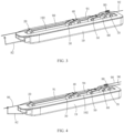
FIG. 1 is a schematic view of a slave-end apparatus for an interventional robot according to a first embodiment of the present disclosure; -
FIG. 2 is another schematic view of the slave-end apparatus inFIG. 1 ; -
FIG. 3 is a schematic view of a slave-end apparatus for an interventional robot according to a second embodiment of the present disclosure; -
FIG. 4 is another schematic view of the slave-end apparatus inFIG. 3 ; -
FIG. 5 is a schematic view of the slave-end apparatus inFIG. 3 in which two drive mechanisms are added; and -
FIG. 6 is a schematic view of the slave-end apparatus inFIG. 3 in which only two drive mechanisms are remained. - For clear description and better understanding of the technical problem to be solved, technical solutions, and advantages of the present disclosure, the present disclosure is further described in detail with reference to the accompanying drawings and specific embodiments. It should be understood that the embodiments described here are only exemplary ones for illustrating the present disclosure, and are not intended to limit the present disclosure.
- In the description of the present disclosure, it should be noted that unless otherwise specified and defined, the terms "mounted," "coupled," "connected," "fixed," and derivative forms thereof shall be understood in a broad sense, which, for example, may be understood as fixed connection, detachable connection or integral connection or even connected in a relative movement fashion; may be understood as mechanical connection or electrical connection, or understood as direct connection, indirect connection via an intermediate medium, or communication between the interiors of two elements or interactions between two elements. Persons of ordinary skill in the art may understand the specific meanings of the above terms in the present application according to the actual circumstances and contexts.
- In the description of the present disclosure, the terms "length," "diameter," "upper," "lower," "front," "rear," "left," "right," "vertical," "horizontal," "top," "bottom," "inner," "outer," and the like indicate orientations or positional relationships which are based on the illustrations in the accompanying drawings, and these terms are merely for ease and brevity of the description, instead of indicating or implying that the devices or elements shall have a particular orientation and shall be structured and operated based on the particular orientation. Accordingly, these terms shall not be construed as limiting the present disclosure.
- The term "distal from" indicates a direction facing towards a patient, and the term "proximal to" indicates a direction facing away from the patient. The terms "up" and "upper" indicate a direction facing away from a direction of gravity, and the terms "bottom," "down," and "lower" indicate a direction facing towards the direction of gravity. The term "forward" indicates a direction along which a guide wire or a catheter moves to the body of the patient. The term "backward" indicates a direction along which the guide wire or the catheter moves out of the body of the patient. The term "inwardly" indicates an inner portion of a feature. The term "outwardly" indicates an outer portion of a feature. The term "rotation" includes "forward rotation" and "reverse rotation," wherein the "forward rotation" indicates a direction along which the guide wire or the catheter rotates to move into the body of the patient, and the "reverse rotation" indicates a direction along which the guide wire or the catheter rotates to move out of the body of the patient.
- In addition, terms of "first" and "second" are only used for description, but shall not be understood as indication or implication of relative importance or implicit indication of the number of the specific technical features. Therefore, the features defined by the terms "first" and "second" may explicitly or implicitly include one or more of these features. In addition, in the description of the present disclosure, the term "multiple," "more," or "a plurality of" refers to at least two unless otherwise specified.
- The guide wire herein includes, but is not limited to, a guide wire, a micro guide wire, a stent and the like guiding and supporting interventional medical instruments. The catheter includes, but is not limited to, a guide catheter, a micro catheter, an angiographic catheter, a multifunctional catheter (also referred to as a middle catheter), a thrombolytic catheter, a balloon dilatation catheter, a balloon-expandable stent catheter and the like interventional medical instruments for treatment.
- As illustrated in
FIG. 1 and FIG. 2 , a first embodiment of the present disclosure provides a slave-end apparatus for an interventional robot. The apparatus includes: abody 10, drivemechanisms body 10, afront clamper 18 and a rear clamper (not illustrated). - The
body 10 is elongated, and is provided with alinear guide rail 102. Thedrive mechanisms guide rail 102, and are slidable along theguide rail 102. - Each of the drive mechanisms is configured to clamp, push (including forward movement and backward movement) and rotate (including forward rotation and reverse rotation) the catheter and the guide wire, or may be configured to simultaneously clamp, push (including forward movement and backward movement) and rotate (including forward rotation and reverse rotation) both the catheter and the guide wire, such that a plurality of catheters and a plurality of guide wires collaboratively move. The specific structures of the
drive mechanisms drive mechanisms drive mechanism 12 has a different structure. Thedrive mechanism 14 includes: a first assembly configured to cooperate with thedrive mechanism 12 to clamp and rotate one catheter, and a second assembly configured to cooperate with thedrive mechanism 12 to clamp and rotate another catheter. Thedrive mechanism 16 includes: a first assembly configured to cooperate with the second assembly of thedrive mechanism 14 to clamp and rotate the another catheter, and a second assembly configured to cooperate with the second assembly of thedrive mechanism 14 to clamp and rotate the guide wire. Thedrive mechanism 16 includes arapid exchange mechanism 162 configured to cooperate with the first assembly of thedrive mechanism 16. - In this embodiment, the
drive mechanism 12, and the second assemblies of thedrive mechanisms Chinese Patent Application No. 202110674955 3 - The
front clamper 18 is positioned at a front portion of thebody 10, proximal to thedrive mechanisms body 10. For details, reference may be made to the description of therear clamper 70. In this embodiment, thefront clamper 18 and the rear clamper are fixed on thebody 10, and may be movable relative to thebody 10 where necessary. In other embodiments, thefront clamper 18 and the rear clamper may also be mounted separately from thebody 10. - Before an operation, some preparations need to be made. Specifically, a first catheter, a second catheter and a first guide wire that are suitable (for example, those with suitable lengths and diameters) are selected, and the first catheter and the second catheter are washed with normal saline and exhausted. The second catheter is manually led into the first catheter to go beyond the first catheter by a distance, and the first guide wire is led into the second catheter to go beyond the second catheter by a distance. For example, the head of the first guide wire goes beyond the second catheter by about 10 cm. The
drive mechanisms drive mechanisms drive mechanism 14 and the first assembly of thedrive mechanism 16 are caused to cooperate to clamp the second catheter, and the second assembly of thedrive mechanism 16 is cause to clamp the first guide wire. In this way, the first catheter, the second catheter and the first guide wire are fixed. - When starting the operation, a master-end console (for example, the master-end operation handle for the interventional robot as disclosed in
Chinese Patent Application No. 202110654379.8 Chinese Patent Application No. 202110649908.5 drive mechanisms drive mechanisms guide rail 102 to drive the first catheter, the second catheter and the first guide wire to move forward, and thedrive mechanisms drive mechanisms - In this embodiment, the first assemblies of the
drive mechanisms drive mechanisms drive mechanisms drive mechanisms - In a case that the first catheter moves forward to a desired position, the first catheter is manually taken off from the first assemblies of the
drive mechanisms front clamper 18 clamps the first catheter to prevent movement thereof. The second catheter is manually taken off from the second assembly of thedrive mechanism 14 and the first assembly of thedrive mechanism 16, and thedrive mechanisms guide rail 102 to clamp the second catheter. Thedrive mechanism 16 may be remotely manipulated by the master-end console to drive the first guide wire to move backward, or the first guide wire may be manually moved backward. In a case that the first guide wire moves backward to the introducer, the first guide wire is taken off from the second assembly of thedrive mechanism 16, and is soaked into heparin water. It should be noted that in this process, the first catheter shall not be pushed, to prevent the head of the first catheter from moving in the vessel. - The
drive mechanism 16 is caused to move backward to a suitable position. A third catheter (for example, a micro catheter) and a second guide wire that are thinner (for example, with a diameter of 0.014 in - 0.035 cm) are selected. The second guide wire is manually led into the third catheter, which are then led into the second catheter, and the third catheter and the second guide wire are respectively clamped by the second assembly of thedrive mechanism 14, the first assembly of thedrive mechanism 16 and the second assembly of thedrive mechanism 16. In this way, the third catheter and the second guide wire are fixed. In this embodiment, the third catheter is connected to the Y adapter; the Y adapter is fixed on thedrive mechanism 16, and is clamped by the first assembly of thedrive mechanism 16; and a Luer connector of the Y adapter is rotated, under cooperation of the second assembly of thedrive mechanism 14, to drive the third catheter to rotate. With respect to thefront clamper 18 configured to clamp the first catheter, thefront clamper 18 may also rotate the first catheter by rotating the Luer connector of the Y adapter. - Further, the
drive mechanisms front clamper 18. The position of the second guide wire is determined by contrast radiography. In a case that the second guide wire reaches a designated position (generally, the second guide wire needs to run through the lesion of the patient for operation, except possible treatment of aneurysm embolization), thefront clamper 18 and thedrive mechanisms drive mechanisms - In the case that the second guide wire reaches the designated position, by using the master-end console, the
drive mechanism 16 is remotely manipulated to cause the third catheter to move backward. In the meantime, the second guide wire is maintained as not moving. For example, the rear clamper takes over to clamp the second guide wire to prevent movement thereof. In a case that the head of the third catheter moves backward to the introducer, in the catheter room, the third catheter is manually taken off from thedrive mechanisms drive mechanism 16 may take over to clamp the second guide wire, and maintain the front clamper, thedrive mechanisms drive mechanism 16 as respectively fixing the first catheter, the second catheter and the second guide wire. - In other embodiments, in a case that the
front clamper 18 clamps the first catheter to prevent movement thereof, thedrive mechanisms drive mechanisms drive mechanisms drive mechanisms - In other embodiments, the front portion of the
body 10 is provided with a plurality offront clampers 18, and in this case, the first catheter may be pushed for multiple times. In a case that the catheter is pushed to a desired position, one of thefront clampers 18 is caused to clamp the catheter. - In the catheter room again, the tail of the second guide wire is caused to run into a rapid exchange balloon dilatation catheter. The rapid exchange balloon dilatation catheter moves forward along with the second guide wire. In this case, the
rapid exchange mechanism 162 clamps the rapid exchange balloon dilatation catheter. - Further, by using the master-end console, the
rapid exchange mechanism 162 is remotely manipulated, such that the rapid exchange balloon dilatation catheter moves forward to the lesion of the patient for operation (not going beyond the head of the second guide wire). In this process, the position and angle of the second guide wire need to be finely adjusted by forward rotation, reverse rotation, forward movement, and backward movement according to actual needs. In a case that the rapid exchange balloon dilatation catheter reaches the lesion of the patient for operation, a contrast medium is filled into the rapid exchange balloon dilatation catheter in the catheter room for pre-dilatation, and a vasodilation effect is determined by contrast radiography. In a case that the vasodilation effect is achieved, the contrast medium is extracted from the rapid exchange balloon dilatation catheter. Further, by using the master-end console, therapid exchange mechanism 162 is remotely manipulated to move backward to the introducer. In the process that the rapid exchange balloon dilatation catheter moves backwards, the position of the second guide wire remains unchanged. With respect to some operations, vasodilation needs to be performed for multiple times. Therefore, the rapid exchange balloon dilatation catheter may move forward and move backward for multiple times. - Further, in the catheter room again, the rapid exchange balloon dilatation catheter is manually taken off from the
rapid exchange mechanism 162, and then causes a balloon-expandable stent catheter is caused to run into the second guide wire and to be clamped on therapid exchange mechanism 162. For details about the specific process, reference may be made to the above process of the rapid exchange balloon dilatation catheter, which are thus not described herein any further. - Further, by using the master-end console, the
rapid exchange mechanism 162 is remotely manipulated, such that the rapid exchange balloon dilatation catheter is pushed along the second guide wire to the lesion of the patient for operation (a narrow vessel site that has been expanded). In this process, the position and angle of the second guide wire need to be finely adjusted by forward rotation, reverse rotation, forward movement, and backward movement according to actual needs. When the rapid exchange balloon-expandable stent catheter reaches the lesion of the patient for operation (the vessel side that has been expanded), the position of the rapid exchange balloon-expandable stent catheter is fine-tuned, after determination, the rapid exchange balloon-expandable stent catheter is filled with the contrast medium in the catheter room, such that the stent is shaped. It is confirmed by contrast radiography that the placement of the balloon-expandable stent is correct, i.e., the contrast medium may be extracted and therapid exchange mechanism 162 is manipulated to drive the rapid exchange balloon-expandable stent catheter to move backward to the introducer, whereas the balloon-expandable stent remains in the lesion of the patient for operation. In the catheter room, the rapid exchange balloon-expandable stent catheter is manually taken off from therapid exchange mechanism 162, and is put into the heparin water. - Further, by using the master-end console, the
drive mechanisms front clamper 18 and thedrive mechanisms - In the above process, the rapid exchange catheter is used, and therefore, the catheter needs to be clamped, pushed and rotated by a
rapid exchange mechanism 162. In a case that a coaxial exchange catheter is used, where the tail of the second guide wire is caused to run into the coaxial exchange catheter, the coaxial exchange catheter is clamped, pushed and rotated by the coaxial exchange mechanism, such that the coaxial exchange catheter moves forward to an appropriate position along the second guide wire or moves backward to the introducer. Regardless of therapid exchange mechanism 162 or the coaxial exchange mechanism, the clamping, pushing and rotating of the rapid exchange catheter and the coaxial exchange catheter may be practiced by means of roller driving. - For details about how the master-end console remotely manipulates the
drive mechanisms rapid exchange mechanism 162 to move, reference may be made to the master-end control module for the interventional robot as disclosed inChinese Patent Application 202110649908.5 drive mechanisms rapid exchange mechanism 162, and this operation lever may manipulate thedrive mechanisms rapid exchange mechanism 162 in a time-division manner, and the other operation lever is configured to manipulate thedrive mechanism 16. Optionally, the master-end console includes more than two operation levers, for example, four operation levers, which are respectively configured to remotely manipulate thedrive mechanisms rapid exchange mechanism 162. - In the above, the movement and control process of the present disclosure has been described by taking "balloon-expandable stent angioplasty" as an example. Indeed, the present disclosure may also be used in a variety of procedures including contrast radiography, embolization, thrombectomy, and the like. The
drive mechanisms front clamper 18 may be freely adapted according to the actual needs of the operation, i.e., thedrive mechanisms front clamper 18 may all be easily disassembled and assembled. Where more complicated operations are performed, more drive mechanisms and front clampers may be deployed. In a case that more drive mechanisms and front clampers are deployed, the collaborative movement of a plurality of catheters corresponding to one guide wire or corresponding to a plurality of guide wires may be practiced. A rapid exchange mechanism is provided for each drive mechanism that constantly clamps the catheter, and is either removably mounted to the drive mechanism or integrally formed with the drive mechanism. In case of performing simple examination procedures, only two of the drive mechanisms, such as thedrive mechanisms 12 and 16 (or thedrive mechanisms drive mechanism 14 according to the actual needs) and thefront clamper 162 are used. In the case, the other drive mechanisms are removed from thebody 10. - The following describes a control process where in the present disclosure, only the
drive mechanisms front clamper 162 collaboratively push two catheters and one guide wire. - In the preparations for the operation, two catheters (a thick catheter and a thin catheter) and two guide wires (a thick guide wire and a thin guide wire) with appropriate diameters and lengths are selected according to the position of a vascular lesion, and the two catheters are washed with normal saline and exhausted. An interventional robot is started to complete initialization. An introducer is placed for a patient for operation. The thick guide wire is manually led into the thick catheter and is caused to move out of the thick catheter by a distance, and then the thick guide wire and the thick catheter are together placed into the introducer. The first assemblies of the
drive mechanism 12 and thedrive mechanism 16 are caused to cooperate to clamp the thick catheter (connected to the Y adapter), and the second assembly of thedrive mechanism 16 is caused to clamp the thick guide wire. In this way, the thick catheter and the thick guide wire are fixed. - When starting the operation, by using the master-end console, the
drive mechanisms drive mechanisms front clamper 18 clamps the thick catheter to prevent movement thereof. It should be noted that in this process, the thick catheter shall not be pushed, to prevent the head of the thick catheter from moving in the vessel. Thedrive mechanism 16 may be remotely manipulated by the master-end console to drive the thick guide wire to move backward, or the thick guide wire may be manually moved backward. In a case that the thick guide wire moves backward to the introducer, the thick guide wire is taken off from the second assembly of thedrive mechanism 16, and is soaked into the heparin water. - The
drive mechanisms drive mechanisms drive mechanism 16, and is clamped by the first assembly of thedrive mechanism 16; and under cooperation of thedrive mechanism 14, a Luer connector of the Y adapter is rotated to drive the thin catheter to rotate. - Further, by using the master-end console, the
drive mechanisms drive mechanisms - Further, in the catheter room again, the tail of the thin guide wire is caused to run into a rapid exchange balloon-expandable stent catheter. The rapid exchange balloon-expandable stent catheter moves forward along with the thin guide wire and runs into the thin catheter, specifically, the Y adapter connecting the thin catheter. In this case, the rapid 20
exchange mechanism 162 clamps the rapid exchange balloon-expandable stent catheter. - Further, by using the master-end console, the
rapid exchange mechanism 162 is remotely manipulated, such that the rapid exchange balloon dilatation catheter moves forward to the lesion of the patient for operation (not going beyond the head of the thin guide wire). In this process, the position and angle of the thin catheter and the thin guide wire need to be finely adjusted by forward rotation, reverse rotation, forward movement, and backward movement according to actual needs. When the rapid exchange balloon-expandable stent catheter reaches the lesion of the patient for operation, the position of the rapid exchange balloon-expandable stent catheter is fine-tuned, after determination, the rapid exchange balloon-expandable stent catheter is filled with the contrast medium in the catheter room, such that the stent is shaped. It is confirmed by contrast radiography that the placement of the balloon-expandable stent is correct, i.e., the contrast medium may be extracted and therapid exchange mechanism 162 is manipulated to drive the rapid exchange balloon-expandable stent catheter to move backward to the introducer, whereas the balloon-expandable stent remains in the lesion of the patient for operation. In the process that the rapid exchange balloon-expandable stent catheter moves backwards, the positions of the thick catheter, the thin catheter and the thin guide wire remain unchanged. In the catheter room, the rapid exchange balloon-expandable stent catheter is manually taken off from therapid exchange mechanism 162, and is put into the heparin water. - Further, by using the master-end console, the
drive mechanisms front clamper 18 and thedrive mechanisms - In the above process, in a case that a coaxial exchange catheter is used, where the tail of the thin guide wire is caused to run into the coaxial exchange catheter, the coaxial exchange catheter is clamped, pushed and rotated by the coaxial exchange mechanism, such that the coaxial exchange catheter moves forward to an appropriate position along the thin guide wire or moves backward to the introducer.
- As illustrated in
FIG. 3 and FIG. 4 , a second embodiment of the present disclosure provides a slave-end apparatus for an interventional robot. The apparatus includes: abody 19, drivemechanisms rear clamper 70, arapid exchange mechanism 80 and afront clamper 82 that are movably mounted on thebody 19. - The
body 19 is elongated, and is provided with alinear channel 192. Thedrive mechanisms channel 192, and are movable along the channel. In this embodiment, thedrive mechanisms body 19. For example, a linear guide rail is fixed on thebody 19, and thedrive mechanisms - Each of the drive mechanisms is configured to clamp, push (including forward movement and backward movement) and rotate (including forward rotation and reverse rotation) the catheter and the guide wire, or may be configured to simultaneously clamp, push (including forward movement and backward movement) and rotate (including forward rotation and reverse rotation) both the catheter and the guide wire, such that a plurality of catheters and one guide wire collaboratively move. Each of the drive mechanisms includes: a clamping assembly configured to clamp the catheter or the guide wire, and a rotating assembly configured to rotate the catheter or the guide wire. The rotating assembly may be an active rotating assembly or a passive rotating assembly. The rotating assemblies may be all active rotating assemblies, or may be partially active rotating assemblies and partially passive rotating assemblies. Clamping of the catheters by the
drive mechanisms - The clamping assemblies and rotating assemblies of the
drive mechanisms Chinese Patent Application No. 202110674959 3 - In other embodiments, the specific structures of the
drive mechanisms - In this embodiment, the
drive mechanisms guide catheter 90 from being bent. In fact, it is preferable that thedrive mechanisms guide catheter 90, such that theguide catheter 90 is stretched straight, without being bent. Likewise, thedrive mechanisms drive mechanism 60 is configured to clamp, push and rotate aguide wire 92. Therear clamper 70 is configured to clamp and push theguide wire 92. Therapid exchange mechanism 80 and thedrive mechanism 50 may be detachably fixed to each other, and may be configured to clamp and push a rapid exchange catheter. - The
rear clamper 70 is positioned at a rear portion of thebody 19. Thefront clamper 82 is positioned at a front portion of thebody 19, proximal to thedrive mechanisms front clamper 82 and therear clamper 70 are fixed on thebody 19, and may be movable relative to thebody 19 where necessary. In other embodiments, thefront clamper 82 and therear clamper 70 may also be mounted separately from thebody 19. - For the preparations of the operation, a
guide catheter 90, amultifunctional catheter 91 and aguide wire 92 that are suitable (for example, those with suitable lengths and diameters) need to selected, and the selectedguide catheter 90 andmultifunctional catheter 91 are washed with normal saline and exhausted. Themultifunctional catheter 91 is manually led into theguide catheter 90 to go beyond theguide catheter 90 by a distance, theguide wire 92 is led into themultifunctional catheter 91 to go beyond themultifunctional catheter 91 by a distance, for example, the head of theguide wire 92 goes beyond themultifunctional catheter 91 by about 10 cm. Thedrive mechanisms guide catheter 90, themultifunctional catheter 91 and theguide wire 92 are together placed and led into an introducer (for example, femoral artery, radial artery or the like) of a patient for operation, the clamping assemblies of thedrive mechanisms guide catheter 90, the clamping assemblies of thedrive mechanisms multifunctional catheter 91, and the clamping assembly of thedrive mechanism 60 and arear clamper 70 are caused to clamp theguide wire 92. In this way, theguide catheter 90, themultifunctional catheter 91 and theguide wire 92 are fixed. - When starting the operation, a master-end console (for example, the master-end operation handle for the interventional robot as disclosed in
Chinese Patent Application No. 202110654379.8 Chinese Patent Application No. 202110649908 5 drive mechanisms rear clamper 70 and therapid exchange mechanism 80 to move. Specifically, thedrive mechanisms guide catheter 90 and move along achannel 192 to drive theguide catheter 90 to move forward, and the rotating assemblies of thedrive mechanisms guide catheter 90. In a case that thedrive mechanism 20 moves to an extreme position (for example, thedrive mechanism 20 moves to a distal end of thechannel 192 and is to be restored to release theguide catheter 90, thedrive mechanism 30 clamps theguide catheter 90 to prevent movement thereof. In a case that thedrive mechanism 20 is restored to a position proximal to thedrive mechanism 30, the clamping assembly of thedrive mechanism 20 clamps theguide catheter 90 again, and thedrive mechanisms guide catheter 90 to move forward, and the rotating assemblies of thedrive mechanisms guide catheter 90. Such operations are repeated until theguide catheter 90 moves to a desired position. - In this process, the
drive mechanisms multifunctional catheter 91 and move along thechannel 192 to drive themultifunctional catheter 91 to move forward, and the rotating assemblies of thedrive mechanisms multifunctional catheter 91. In a case that thedrive mechanism 40 moves to an extreme position (for example, a distance from thedrive mechanism 40 to thedrive mechanism 30 approaches a threshold) and is to be restored to release themultifunctional catheter 91, thedrive mechanism 50 clamps themultifunctional catheter 91 to prevent movement thereof. In a case that thedrive mechanism 40 is restored to a position proximal to thedrive mechanism 50, the clamping assembly of thedrive mechanism 40 clamps themultifunctional catheter 91 again, thedrive mechanisms multifunctional catheter 91 to move forward, and the rotating assemblies of thedrive mechanisms multifunctional catheter 91. Such operations are repeated until themultifunctional catheter 91 moves to a desired position. - In the above process, the
drive mechanism 60 and therear clamper 70 simultaneously or non-simultaneously collaboratively clamp theguide wire 92 and move along thechannel 192 to drive theguide wire 92 to move forward, and the rotating assembly of thedrive mechanism 60 simultaneously or non-simultaneously rotates theguide wire 92. In a case that thedrive mechanism 60 moves to an extreme position (for example, a distance from thedrive mechanism 60 to thedrive mechanism 50 approaches a threshold) and is to be restored to release theguide wire 92, therear clamper 70 clamps theguide wire 92 to prevent movement thereof. In a case that thedrive mechanism 60 is restored, the clamping assembly of thedrive mechanism 60 clamps theguide wire 92 again, thedrive mechanism 60 and therear clamper 70 are caused to collaboratively drive theguide catheter 92 to move forward, and the rotating assembly of thedrive mechanism 60 simultaneously or non-simultaneously rotates theguide wire 92. Such operations are repeated until theguide wire 92 moves to a desired position. In other embodiments, at the beginning, only thedrive mechanism 60 clamps theguide wire 92, but therear clamper 70 does not clamp theguide wire 92. In the case that thedrive mechanism 60 is restored, therear clamper 70 clamps theguide wire 92. In a case that thedrive mechanism 60 is restored and clamps theguide wire 92 again, therear clamper 70 releases theguide wire 92. Such operations are repeated such that thedrive mechanism 60 and therear clamper 70 alternately clamp theguide wire 92. - For details about how the
drive mechanisms rear clamper 70 and therapid exchange mechanism 80 are remotely manipulated to move by using the master-end console, reference may be made to the master-end control module for the interventional robot as disclosed inChinese Patent Application 202110649908.5 drive mechanisms rapid exchange mechanism 80, and this operation lever may manipulate thedrive mechanism drive mechanisms rapid exchange mechanism 80 in a time-division manner, and the other operation lever is configured to manipulate thedrive mechanism 60 and therear clamper 70. Optionally, the master-end console includes more than two operation levers, for example, four operation levers, which are respectively configured to remotely manipulate thedrive mechanisms drive mechanisms drive mechanism 60 and therear clamper 70, and therapid exchange mechanism 80. - In other embodiments, the
drive mechanisms guide catheter 90 and themultifunctional catheter 91 via an Y adapter. That is, theguide catheter 90 and themultifunctional catheter 91 are respectively connected to the Y adapter; the Y adapter is fixed to thedrive mechanisms drive mechanisms drive mechanisms guide catheter 90 and themultifunctional catheter 91 to rotate. - During collaborative pushing of the
guide catheter 90, themultifunctional catheter 91 and theguide wire 92, it needs to be constantly ensured that themultifunctional catheter 91 goes beyond theguide catheter 90 by a distance and theguide wire 92 goes beyond themultifunctional catheter 91 by a distance. In a case that theguide catheter 90, themultifunctional catheter 91 and theguide wire 92 reach some positions of the vessel, thedrive mechanisms rear clamper 70 need to be remotely manipulated by the master-end console, to drive theguide catheter 90, themultifunctional catheter 91 and theguide wire 92 to move forward and backward, and rotate forward and rotate reversely for multiple times. - In a case that the
guide catheter 90 moves forward to a desired position, theguide catheter 90 is fixed. Thedrive mechanism 60 and therear clamper 70 are remotely manipulated by the master-end console, to drive theguide wire 92 to move backward. The process of backward movement is similar to the above process of forward movement. In a case that the head of theguide wire 92 moves backwards to the introducer, in the catheter room, theguide wire 92 is manually taken off from the clamping assembly of thedrive mechanism 60 and therear clamper 70, and is soaked into the heparin water. - The
guide catheter 90 is manually taken off from the clamping assemblies of thedrive mechanisms front clamper 82 takes over to clamp theguide catheter 90 to prevent movement thereof. It should be noted that in this process, theguide catheter 90 shall not be pushed, to prevent the head of theguide catheter 90 from moving in the vessel. Themultifunctional catheter 91 is manually taken off from the clamping assemblies of thedrive mechanisms drive mechanisms multifunctional catheter 91. - In other embodiments, the
front clamper 82 may be telescopic, which extends from a hidden space where a catheter needs to be clamped. With respect to thefront clamper 82 configured to clamp theguide catheter 90, thefront clamper 82 may also rotate theguide catheter 90 by rotating the Luer connector of the Y adapter. In other embodiments, the front portion of thebody 19 is provided with a plurality offront clampers 82, and in this case, the catheter may be pushed for multiple times. In a case that each catheter is pushed to a desired position, one of thefront clampers 82 is caused to clamp the catheter. - The
drive mechanisms rear clamper 70 are adjusted to suitable positions. Amicro catheter 94 and amicro guide wire 96 that are thinner (for example, with a diameter of 0.014 in - 0.035 cm) are selected. Themicro guide wire 96 is manually led into themicro catheter 94 and themicro guide wire 96 and themicro catheter 94 are led into themultifunctional catheter 91, and themicro catheter 94 and themicro guide wire 96 are respectively clamped by the clamping assemblies of thedrive mechanisms drive mechanism 60, and therear clamper 70. In this way, themicro catheter 94 and themicro guide wire 96 are fixed. In other embodiments, themicro catheter 94 is connected to an Y adapter. The Y adapter is fixed to thedrive mechanism 50. The clamping assembly of thedrive mechanism 50 clamps the Y adapter, and the rotating assembly of thedrive mechanism 50 rotates a Luer connector of the Y adapter to drive themicro catheter 94 to rotate. - Further, by using the master-end console, the
drive mechanisms rear clamper 70 are remotely manipulated to move. For details about the specific process, reference may be made to the forward movement of theguide catheter 90, themultifunctional catheter 91 and theguide wire 92, which are thus not described herein any further. Themultifunctional catheter 91 is caused to move forward to the vessel farther. In a case that themicro catheter 94 and themicro guide wire 96 move forward to the head of themultifunctional catheter 91, themicro catheter 94 and themicro guide wire 96 are further pushed to a lesion (that is, a target vessel stenosis site) of the patient for operation. The position of themicro guide wire 96 is determined by contrast radiography. In a case that themicro guide wire 96 reaches a designated position (generally, themicro guide wire 96 needs to run through the lesion of the patient for operation, except possible treatment of aneurysm embolization), thedrive mechanisms drive mechanisms drive mechanism 60 and therear clamper 70 respectively fix themultifunctional catheter 91, themicro catheter 94 and themicro guide wire 96. In a case that themicro guide wire 96 fails to reach the designated position, thedrive mechanisms rear clamper 70 are repeatedly remotely manipulated to move, until themicro guide wire 96 reaches the designated position. - In other embodiments, the
drive mechanisms rear clamper 70 may be remotely manipulated, by using the master-end console, to drive themultifunctional catheter 91 and theguide wire 92 to move backward together. In a case that the heads of themultifunctional catheter 91 and theguide wire 92 move backward to the introducer, in the catheter room, themultifunctional catheter 91 and theguide wire 92 are manually taken off from the clamping assemblies of thedrive mechanisms rear clamper 70, and are soaked into the heparin water. Then, theguide catheter 90 is taken off from the clamping assemblies of thedrive mechanisms front clamper 82 takes over to clamp theguide catheter 90 to prevent movement thereof. It should be noted that in this process, theguide catheter 90 shall not be pushed, to prevent the head of theguide catheter 90 from moving in the vessel. Two catheters and one guide wire that are suitable are selected, and the catheters and the guide wire are placed into theguide catheter 90 all together. Thedrive mechanisms drive mechanisms drive mechanisms drive mechanism 60 and therear clamper 70 are caused to clamp the guide wire. In this way, the two catheters and the one guide wire are fixed. For details about the subsequent process of forward movement, reference may be made to the forward movement of theguide catheter 90, themultifunctional catheter 91 and theguide wire 92, which are thus not described herein any further. - In the case that the
micro guide wire 96 reaches the designated position, by using the master-end console, thedrive mechanisms micro catheter 94 to move backward. In the meantime, themicro guide wire 96 is maintained as not moving. For example, as thedrive mechanism 60 moves backward, therear clamper 70 takes over to clamp themicro guide wire 96 to prevent movement thereof. In a case that the head of themicro catheter 94 moves backward to the introducer, in the catheter room, themicro catheter 94 is manually taken off from thedrive mechanisms drive mechanism 60 may take over to clamp themicro guide wire 96, and maintain thefront clamper 82, thedrive mechanisms drive mechanism 60 as respectively fixing theguide catheter 90, themultifunctional catheter 91 and themicro guide wire 96. - Further, in the catheter room again, the tail of the
micro guide wire 96 is caused to run into a rapid exchangeballoon dilatation catheter 98. The rapid exchangeballoon dilatation catheter 98 moves forward along with themicro guide wire 96. In this case, therapid exchange mechanism 80 clamps the rapid exchangeballoon dilatation catheter 98. - Further, by using the master-end console, the
rapid exchange mechanism 80 is remotely manipulated, such that the rapid exchangeballoon dilatation catheter 98 moves forward to the lesion of the patient for operation (not going beyond the head of the micro guide wire 96). In this process, the position and angle of themicro guide wire 96 need to be finely adjusted by forward rotation, reverse rotation, forward movement, and backward movement according to actual needs. In a case that the rapid exchangeballoon dilatation catheter 98 reaches the lesion of the patient for operation, a contrast medium is filled into the rapid exchangeballoon dilatation catheter 98 in the catheter room for pre-dilatation, and a vasodilation effect is determined by contrast radiography. In a case that the vasodilation effect is achieved, the contrast medium is extracted from the rapid exchangeballoon dilatation catheter 98. Further, by using the master-end console, therapid exchange mechanism 80 is remotely manipulated to move backward to the introducer. In the process that the rapid exchangeballoon dilatation catheter 98 moves backwards, the position of themicro guide wire 96 remains unchanged. With respect to some operations, vasodilation needs to be performed for multiple times. Therefore, the rapid exchange balloon dilatation catheter may move forward and move backward for multiple times. - Further, in the catheter room again, the rapid exchange
balloon dilatation catheter 98 is manually taken off from therapid exchange mechanism 80, and then a balloon-expandable stent catheter is caused to run into themicro guide wire 96 and to be clamped on therapid exchange mechanism 80. For details about the specific process, reference may be made to the above process of the rapid exchangeballoon dilatation catheter 98, which are thus not described herein any further. - Further, by using the master-end console, the
rapid exchange mechanism 80 is remotely manipulated, such that the rapid exchange balloon dilatation catheter is pushed along themicro guide wire 96 to the lesion of the patient for operation (a narrow vessel site that has been expanded). In this process, the position and angle of themicro guide wire 96 are finely adjusted by forward rotation, reverse rotation, forward movement, and backward movement according to actual needs. When the rapid exchange balloon-expandable stent catheter reaches the lesion of the patient for operation (the vessel side that has been expanded), the position of the rapid exchange balloon-expandable stent catheter is fine-tuned, after determination, the rapid exchange balloon-expandable stent catheter is filled with the contrast medium in the catheter room, such that the stent is shaped. It is confirmed by contrast radiography that the placement of the balloon expandable stent is correct, i.e., the contrast medium may be extracted and therapid exchange mechanism 80 is manipulated to drive the rapid exchange balloon-expandable stent catheter to move backward to the introducer, whereas the balloon-expandable stent remains in the lesion of the patient for operation. In the catheter room, the rapid exchange balloon-expandable stent catheter is manually taken from therapid exchange mechanism 80, and is put into the heparin water. - Further, by using the master-end console, the
drive mechanisms rear clamper 70 are remotely manipulated to move, such that themultifunctional catheter 91 and themicro guide wire 96 move backward to the introducer. Finally, in the catheter room, themultifunctional catheter 91 and themicro guide wire 96 are manually taken off from the clamping assemblies of thedrive mechanisms rear clamper 70, theguide catheter 90 is taken from thefront clamper 82, themultifunctional catheter 91, themicro guide wire 96 and theguide catheter 90 are withdrawn from the introducer and placed into the heparin water, and then the introducer is removed and post-operation treatment is carried out to complete the operation. - In the above process, the rapid exchange catheter is used, and therefore, the catheter needs to be clamped, pushed and rotated by a
rapid exchange mechanism 80. In a case that a coaxial exchange catheter is used, where the tail of themicro guide wire 96 is caused to run into the coaxial exchange catheter, the coaxial exchange catheter is clamped, pushed and rotated by the coaxial exchange mechanism, such that the coaxial exchange catheter moves forward to an appropriate position along themicro guide wire 96 or moves backward to the introducer. Regardless of therapid exchange mechanism 80 or the coaxial exchange mechanism, the clamping, pushing and rotating of the rapid exchange catheter and the coaxial exchange catheter may be practiced by means of roller driving. - In the above, the movement and control process of the present disclosure has been described by taking "balloon-expandable stent angioplasty" as an example. Indeed, the present disclosure may also be used in a variety of procedures including contrast radiography, embolization, thrombectomy, and the like. The
drive mechanisms rear clamper 70 and therapid exchange mechanism 80 may be freely adapted according to the actual needs of the operation, i.e., thedrive mechanisms rear clamper 70 and therapid exchange mechanism 80 may all be easily disassembled and assembled. Where more complicated surgeries are performed, more drive mechanisms, rear clampers and rapid exchange mechanisms may be deployed. In a case that more drive mechanisms and rear clampers are deployed, the collaborative movement of a plurality of catheters corresponding to one guide wire or corresponding to a plurality of guide wires may be practiced. As illustrated inFIG. 5 , two drive mechanisms are added to clamp and rotate more catheters. For details, reference may be made to the above-mentioned "balloon stent angioplasty." A rapid exchange mechanism is provided for each drive mechanism that constantly clamps the catheter, and is either removably mounted to the drive mechanism or integrally formed with the drive mechanism. In case of performing simple examination procedures, such as an angiographic procedure, only two of thedrive mechanisms drive mechanisms FIG. 6 , the other drive mechanisms, therear clamper 70 and therapid exchange mechanism 80 are removed from thebody 19. - In the above description, the master-end console and the operable table on which the master-end console is deployed are outside the catheter room. In fact, the master-end console and the operable table may also be deployed in a separate space in the catheter room, as long as X-ray radiation can be isolated and the physician is exempt from the X-ray radiation.
- The above only describes how the catheter and the guide wire are replaced in some cases. In fact, the replacement of the catheter and the guide wire may be completely determined according to the actual needs of the operation and the personal operating habits. The placement is not limited to the above methods for replacing the catheter and the guide wire.
- According to the present disclosure, the first drive mechanism and the second drive mechanism may be remotely manipulated to move along the same axial direction on the body, such that a plurality of catheters and a plurality of guide wires collaboratively move to desired positions. In case of replacing the catheter and the guide wire, the front clamper clamps the first catheter to prevent movement thereof. This blocks radiation by X rays and protects health of human bodies. In addition, the robot may more accurately control the catheter and the guide wire, which not only reduces working intensity, but also avoids severe mistakes.
- Persons of ordinary skill in the art should understand that all or part of steps of the method may be implemented by programs instructing related hardware. The programs may be stored in a computer-readable storage medium, for example, a read-only memory, a magnetic disk, or a compact disc read-only memory. Alternatively, all or part of the steps of the embodiments described above may be implemented using one or more integrated circuits. Accordingly, various modules/units in the above-mentioned embodiments may be implemented in the form of hardware or in the form of software functional modules. The present disclosure is not limited to any specific form of hardware or software combination.
- Nevertheless, many other embodiments may also be available for implementation of the present disclosure, and those skilled in the art would recognize that various modifications and changes may be made thereto without departing from the pirit and scope of the present disclosure. These modifications and changes fall within the protection scope set forth in the appended claims.
Claims (8)
- A slave-end apparatus for an interventional robot, comprising: a body (10), and a first drive mechanism (12), a second drive mechanism (14), a third drive mechanism (16) successively mounted on the body (10), the body (10) is elongated, and is provided with a linear guide rail (102), the first drive mechanism (12), the second drive mechanism (14), and the third drive mechanism (16) are slidable along the guide rail (102); whereinthe first drive mechanism (12) is configured to clamp and rotate a first catheter or a second catheter, the second drive mechanism (14) comprises a first assembly configured to together with the first drive mechanism (12) clamp and rotate the first catheter or the second catheter, and a second assembly configured to clamp and rotate the second catheter or a third catheter, and the third drive mechanism (16) comprises a first assembly configured to together with the second assembly of the second drive mechanism (14) clamp and rotate the second catheter or the third catheter, and a second assembly configured to clamp and rotate a first guide wire or a second guide wire; andthe slave-end apparatus is characterized that,the slave-end apparatus further comprises a front clamper (18, 82) positioned at a front side of the body (10), and configured to be retractable and to extend outside of the body (10) from a hidden space to clamp the first catheter so as to keep the first catheter not to move relative to the body (10);the first guide wire is configured to run into the second catheter, the second catheter is configured to run into the first catheter, and the first guide wire is configured to be clamped by the second assembly of the third drive mechanism (16), the second catheter is configured to be clamped by the second assembly of the second drive mechanism (14) and the first assembly of the third drive mechanism (16), and the first catheter is configured to be clamped by the first assembly of the second drive mechanism (14) and the first drive mechanism (12) and to move along an axial direction of the body (10) toward the front clamper (18, 82) to a desired position, the first catheter is configured to be manually taken off from the first drive mechanism (12) and the first assembly of the second drive mechanism (14), the second catheter is configured to be manually taken off from the second assembly of the second drive mechanism (14) and the first assembly of the third drive mechanism (16), and the first guide wire is configured to be taken off from the second assembly of the third drive mechanism (16), the front clamper (18, 82) is configured to clamp the first catheter, and the first drive mechanism (12) and the first assembly of the second drive mechanism (14) are configured to clamp the second catheter respectively, the third catheter is configured to run into the second catheter and the second guide wire is configured to run into the third catheter, the third catheter is configured to be clamped by the second assembly of the second drive mechanism (14) and the first assembly of the third drive mechanism (16), and the second guide wire is configured to be clamped by the second assembly of the third drive mechanism (16) and to move along the axial direction of the body (10) toward the front clamper (18, 82).
- The slave-end apparatus for the interventional robot according to claim 1, wherein the first assembly of the second drive mechanism (14) is configured to clamp an Y adapter connected to the first catheter or the second catheter to clamp the first catheter or the second catheter, and rotate a Luer connector of the Y adapter to drive the first catheter or the second catheter to rotate.
- The slave-end apparatus for the interventional robot according to claim 1, wherein the first assembly of the third drive mechanism (16) is configured to clamp an Y adapter connected to the second catheter or the third catheter to clamp the second catheter or the third catheter, and rotate a Luer connector of the Y adapter to drive the second catheter or the third catheter to rotate.
- The slave-end apparatus for the interventional robot according to claim 1, wherein the second assembly is a slave-end guide wire and catheter twisting apparatus for the interventional robot.
- The slave-end apparatus for the interventional robot according to claim 4, further comprising: a rear clamper (70); wherein in a case that the third drive mechanism (16) moves to an extreme position and is to be restored to release the second guide wire, the rear clamper (70) is configured to clamp the second guide wire to prevent movement thereof.
- The slave-end apparatus for the interventional robot according to claim 5, wherein the rear clamper (70) are respectively positioned at a rear portion of the body (10); whereinthe rear clamper (70) is mounted on the body (10) and movable relative to the body (10); orthe rear clamper (70) is mounted separately from the body (10).
- The slave-end apparatus for the interventional robot according to claim 1, further comprising: an exchange mechanism; wherein the exchange mechanism is a rapid exchange mechanism or a coaxial exchange mechanism.
- The slave-end apparatus for the interventional robot according to claim 7, wherein the exchange mechanism is detachably fixed to the third drive mechanism (16), or the exchange mechanism and the third drive mechanism (16) are integrally designed.
Applications Claiming Priority (5)
| Application Number | Priority Date | Filing Date | Title |
|---|---|---|---|
| CN202110759048 | 2021-07-05 | ||
| CN202110759062 | 2021-07-05 | ||
| CN202111009755.4A CN113729956B (en) | 2021-07-05 | 2021-08-31 | From end device of intervention operation robot |
| CN202111009735.7A CN113693733B (en) | 2021-07-05 | 2021-08-31 | Intervene operation robot from end device |
| PCT/CN2022/102921 WO2023280049A1 (en) | 2021-07-05 | 2022-06-30 | Slave end device for interventional surgical robot |
Publications (3)
| Publication Number | Publication Date |
|---|---|
| EP4137090A1 EP4137090A1 (en) | 2023-02-22 |
| EP4137090A4 EP4137090A4 (en) | 2023-11-22 |
| EP4137090B1 true EP4137090B1 (en) | 2025-06-25 |
Family
ID=84801256
Family Applications (1)
| Application Number | Title | Priority Date | Filing Date |
|---|---|---|---|
| EP22782655.9A Active EP4137090B1 (en) | 2021-07-05 | 2022-06-30 | Slave end device for interventional surgical robot |
Country Status (6)
| Country | Link |
|---|---|
| US (1) | US11998294B2 (en) |
| EP (1) | EP4137090B1 (en) |
| JP (1) | JP7540118B6 (en) |
| ES (1) | ES3037180T3 (en) |
| PL (1) | PL4137090T3 (en) |
| WO (1) | WO2023280049A1 (en) |
Families Citing this family (1)
| Publication number | Priority date | Publication date | Assignee | Title |
|---|---|---|---|---|
| EP4574081A1 (en) * | 2023-12-22 | 2025-06-25 | Caranx Medical | A medical instrument holder and a medical system |
Family Cites Families (38)
| Publication number | Priority date | Publication date | Assignee | Title |
|---|---|---|---|---|
| US6096004A (en) * | 1998-07-10 | 2000-08-01 | Mitsubishi Electric Information Technology Center America, Inc. (Ita) | Master/slave system for the manipulation of tubular medical tools |
| US7766856B2 (en) * | 2001-05-06 | 2010-08-03 | Stereotaxis, Inc. | System and methods for advancing a catheter |
| US20090138025A1 (en) | 2007-05-04 | 2009-05-28 | Hansen Medical, Inc. | Apparatus systems and methods for forming a working platform of a robotic instrument system by manipulation of components having controllably rigidity |
| US7998020B2 (en) * | 2007-08-21 | 2011-08-16 | Stereotaxis, Inc. | Apparatus for selectively rotating and/or advancing an elongate device |
| EP2542290B1 (en) | 2010-03-02 | 2019-11-06 | Corindus, Inc. | Robotic catheter system with variable drive mechanism |
| CN101999941A (en) | 2010-11-29 | 2011-04-06 | 燕山大学 | Tube and wire feeding device for intravascular intervention surgical robot |
| JP2014113181A (en) | 2012-12-06 | 2014-06-26 | Samsung R&D Institute Japan Co Ltd | Automatic insertion device of multiple structure medical tube |
| US9326822B2 (en) * | 2013-03-14 | 2016-05-03 | Hansen Medical, Inc. | Active drives for robotic catheter manipulators |
| US10653863B1 (en) | 2013-03-15 | 2020-05-19 | Corindus, Inc. | Robotic percutaneous device wiper |
| US9408669B2 (en) | 2013-03-15 | 2016-08-09 | Hansen Medical, Inc. | Active drive mechanism with finite range of motion |
| US10376672B2 (en) * | 2013-03-15 | 2019-08-13 | Auris Health, Inc. | Catheter insertion system and method of fabrication |
| FR3022147B1 (en) | 2014-06-12 | 2016-07-22 | Robocath | ROBOTISE MODULE OF SOFT MEDICAL MEDICAL TRAINING |
| KR101712733B1 (en) | 2015-06-23 | 2017-03-06 | 한양대학교 에리카산학협력단 | Robot for Vascular Intervention and System thereof |
| FR3044541B1 (en) | 2015-12-07 | 2017-12-29 | Robocath | ROBOTISE MODULE OF SOFT MEDICAL MEDICAL TRAINING |
| JP6837774B2 (en) | 2016-08-05 | 2021-03-03 | 前沿産業設計研究(深セン)有限公司 | Catheter and guide wire interlocking insertion system |
| AU2018290831A1 (en) | 2017-06-28 | 2019-12-19 | Auris Health, Inc. | Instrument insertion compensation |
| CN107374740B (en) * | 2017-07-06 | 2018-09-11 | 北京理工大学 | A kind of catheter guide wire cooperating intervention robot |
| CN107374739B (en) | 2017-07-06 | 2023-05-02 | 北京理工大学 | An interventional surgery robot slave device and its control method |
| CN107374737B (en) * | 2017-07-06 | 2018-10-30 | 北京理工大学 | A kind of intervention operation robot catheter guide wire cooperating system |
| CN107744405B (en) * | 2017-08-31 | 2024-01-30 | 首都医科大学附属北京天坛医院 | Robot slave device, operating system and control method thereof |
| KR102184889B1 (en) * | 2018-04-19 | 2020-12-01 | (주)엘엔로보틱스 | Roller module for medical robot, driving apparatus for medical robot and medical robot |
| CN109106449B (en) | 2018-07-10 | 2020-04-17 | 上海交通大学 | Cardiovascular and cerebrovascular interventional operation robot and guide wire catheter pushing method thereof |
| US12239405B2 (en) | 2018-09-19 | 2025-03-04 | Siemens Healthineers Endovascular Robotics, Inc. | Robotic assisted movements of elongated medical devices |
| CN109171904B (en) | 2018-09-29 | 2021-04-06 | 郑州大学第一附属医院 | Special cardiovascular interventional therapy device for medical science |
| CN109567947A (en) | 2018-12-29 | 2019-04-05 | 易度河北机器人科技有限公司 | A kind of intervention operation robot is from end device and its control method |
| CN109821138B (en) | 2019-01-29 | 2020-07-03 | 燕山大学 | Minimally invasive vascular intervention surgical robot catheter and guide wire propulsion mechanism |
| CN119655898A (en) | 2019-07-15 | 2025-03-21 | 科林达斯公司 | Manipulation of elongate medical devices |
| EP3982865A4 (en) * | 2019-07-15 | 2023-07-26 | Corindus, Inc. | SYSTEMS, APPARATUS AND METHODS ASSOCIATED WITH ROBOTIC INTERVENTION PROCEDURES USING A PLURALITY OF EXTENDED MEDICAL DEVICES |
| JP2021052933A (en) * | 2019-09-27 | 2021-04-08 | テルモ株式会社 | Protective pipe, medical device assembly, and guide wire attaching method |
| CN111529068A (en) | 2020-05-25 | 2020-08-14 | 绍兴梅奥心磁医疗科技有限公司 | Catheter robot operation support and catheter robot |
| FR3118406B1 (en) * | 2020-12-28 | 2024-05-03 | Robocath | ROBOT CATHETER COMPRISING AT LEAST TWO ELONGATED FLEXIBLE MEDICAL INSTRUMENT TRANSLATION MODULES |
| EP4023183A1 (en) | 2020-12-29 | 2022-07-06 | Robocath | Catheter robot comprising catheter translation modules for flexible elongated medical elements |
| CN112674877A (en) | 2021-01-19 | 2021-04-20 | 王利 | New interventional catheter and interventional surgery robot |
| US20220313962A1 (en) * | 2021-04-01 | 2022-10-06 | Xcath, Inc. | Guidewire controller cassette and using method thereof |
| CN113057718B (en) | 2021-05-06 | 2022-03-08 | 哈尔滨医科大学 | Intravascular plaque cutting device |
| CN113693733B (en) * | 2021-07-05 | 2022-08-09 | 深圳市爱博医疗机器人有限公司 | Intervene operation robot from end device |
| CN113729956B (en) * | 2021-07-05 | 2023-04-28 | 深圳市爱博医疗机器人有限公司 | From end device of intervention operation robot |
| US12035989B2 (en) * | 2021-08-02 | 2024-07-16 | Corindus, Inc. | Systems and methods for a control station for robotic interventional procedures using a plurality of elongated medical devices |
-
2022
- 2022-06-30 WO PCT/CN2022/102921 patent/WO2023280049A1/en not_active Ceased
- 2022-06-30 PL PL22782655.9T patent/PL4137090T3/en unknown
- 2022-06-30 EP EP22782655.9A patent/EP4137090B1/en active Active
- 2022-06-30 JP JP2022555857A patent/JP7540118B6/en active Active
- 2022-06-30 ES ES22782655T patent/ES3037180T3/en active Active
- 2022-10-10 US US17/963,173 patent/US11998294B2/en active Active
Also Published As
| Publication number | Publication date |
|---|---|
| JP7540118B6 (en) | 2024-09-12 |
| JP2023533097A (en) | 2023-08-02 |
| EP4137090A1 (en) | 2023-02-22 |
| US20230032469A1 (en) | 2023-02-02 |
| WO2023280049A1 (en) | 2023-01-12 |
| US11998294B2 (en) | 2024-06-04 |
| EP4137090A4 (en) | 2023-11-22 |
| JP7540118B2 (en) | 2024-08-27 |
| PL4137090T3 (en) | 2025-10-27 |
| ES3037180T3 (en) | 2025-09-29 |
Similar Documents
| Publication | Publication Date | Title |
|---|---|---|
| US20230022245A1 (en) | Slave-end apparatus for interventional robot | |
| CN113693733B (en) | Intervene operation robot from end device | |
| JP7404501B2 (en) | Systems, apparatus and methods for robotic interventional procedures using a plurality of elongated medical devices | |
| CN113729962B (en) | From end device of intervention operation robot | |
| CN113729958B (en) | From end device of intervention operation robot | |
| CN114391961B (en) | Slave end operating device of simple interventional operation robot | |
| CN113729957B (en) | From end device of intervention operation robot | |
| CN114191095B (en) | A synchronized interventional surgical robot | |
| CN115517766B (en) | Interventional operation robot for operating double guide wires and interventional operation robot system | |
| CN218420031U (en) | Multi-guide-rail interventional operation robot slave-end operation device | |
| US11998294B2 (en) | Slave-end apparatus for interventional robot | |
| US12484980B2 (en) | Slave-end apparatus for interventional robot | |
| RU2803871C1 (en) | Slave device for intervention robot | |
| HK40063979B (en) | Slave end device of interventional operation robot | |
| HK40063979A (en) | Slave end device of interventional operation robot | |
| HK40063978B (en) | Slave end device of interventional operation robot | |
| HK40063981B (en) | Slave end device of interventional operation robot | |
| HK40063978A (en) | Slave end device of interventional operation robot | |
| HK40063981A (en) | Slave end device of interventional operation robot | |
| CN118526302A (en) | Modularized platform of surgical robot |
Legal Events
| Date | Code | Title | Description |
|---|---|---|---|
| STAA | Information on the status of an ep patent application or granted ep patent |
Free format text: STATUS: UNKNOWN |
|
| STAA | Information on the status of an ep patent application or granted ep patent |
Free format text: STATUS: THE INTERNATIONAL PUBLICATION HAS BEEN MADE |
|
| PUAI | Public reference made under article 153(3) epc to a published international application that has entered the european phase |
Free format text: ORIGINAL CODE: 0009012 |
|
| STAA | Information on the status of an ep patent application or granted ep patent |
Free format text: STATUS: REQUEST FOR EXAMINATION WAS MADE |
|
| 17P | Request for examination filed |
Effective date: 20221011 |
|
| AK | Designated contracting states |
Kind code of ref document: A1 Designated state(s): AL AT BE BG CH CY CZ DE DK EE ES FI FR GB GR HR HU IE IS IT LI LT LU LV MC MK MT NL NO PL PT RO RS SE SI SK SM TR |
|
| RIN1 | Information on inventor provided before grant (corrected) |
Inventor name: REN, WENYONG Inventor name: OU, YONGHONG |
|
| A4 | Supplementary search report drawn up and despatched |
Effective date: 20231025 |
|
| RIC1 | Information provided on ipc code assigned before grant |
Ipc: A61B 34/35 20160101AFI20231019BHEP |
|
| STAA | Information on the status of an ep patent application or granted ep patent |
Free format text: STATUS: EXAMINATION IS IN PROGRESS |
|
| 17Q | First examination report despatched |
Effective date: 20240812 |
|
| DAV | Request for validation of the european patent (deleted) | ||
| DAX | Request for extension of the european patent (deleted) | ||
| GRAP | Despatch of communication of intention to grant a patent |
Free format text: ORIGINAL CODE: EPIDOSNIGR1 |
|
| STAA | Information on the status of an ep patent application or granted ep patent |
Free format text: STATUS: GRANT OF PATENT IS INTENDED |
|
| INTG | Intention to grant announced |
Effective date: 20250122 |
|
| GRAS | Grant fee paid |
Free format text: ORIGINAL CODE: EPIDOSNIGR3 |
|
| GRAA | (expected) grant |
Free format text: ORIGINAL CODE: 0009210 |
|
| STAA | Information on the status of an ep patent application or granted ep patent |
Free format text: STATUS: THE PATENT HAS BEEN GRANTED |
|
| AK | Designated contracting states |
Kind code of ref document: B1 Designated state(s): AL AT BE BG CH CY CZ DE DK EE ES FI FR GB GR HR HU IE IS IT LI LT LU LV MC MK MT NL NO PL PT RO RS SE SI SK SM TR |
|
| REG | Reference to a national code |
Ref country code: GB Ref legal event code: FG4D |
|
| REG | Reference to a national code |
Ref country code: CH Ref legal event code: EP |
|
| REG | Reference to a national code |
Ref country code: CH Ref legal event code: EP |
|
| REG | Reference to a national code |
Ref country code: IE Ref legal event code: FG4D |
|
| REG | Reference to a national code |
Ref country code: DE Ref legal event code: R096 Ref document number: 602022016565 Country of ref document: DE |
|
| PGFP | Annual fee paid to national office [announced via postgrant information from national office to epo] |
Ref country code: NL Payment date: 20250730 Year of fee payment: 4 |
|
| REG | Reference to a national code |
Ref country code: ES Ref legal event code: FG2A Ref document number: 3037180 Country of ref document: ES Kind code of ref document: T3 Effective date: 20250929 |
|
| REG | Reference to a national code |
Ref country code: NL Ref legal event code: FP |
|
| PG25 | Lapsed in a contracting state [announced via postgrant information from national office to epo] |
Ref country code: FI Free format text: LAPSE BECAUSE OF FAILURE TO SUBMIT A TRANSLATION OF THE DESCRIPTION OR TO PAY THE FEE WITHIN THE PRESCRIBED TIME-LIMIT Effective date: 20250625 |
|
| PGFP | Annual fee paid to national office [announced via postgrant information from national office to epo] |
Ref country code: ES Payment date: 20250803 Year of fee payment: 4 |
|
| PGFP | Annual fee paid to national office [announced via postgrant information from national office to epo] |
Ref country code: DE Payment date: 20250702 Year of fee payment: 4 |
|
| REG | Reference to a national code |
Ref country code: LT Ref legal event code: MG9D |
|
| PG25 | Lapsed in a contracting state [announced via postgrant information from national office to epo] |
Ref country code: NO Free format text: LAPSE BECAUSE OF FAILURE TO SUBMIT A TRANSLATION OF THE DESCRIPTION OR TO PAY THE FEE WITHIN THE PRESCRIBED TIME-LIMIT Effective date: 20250925 Ref country code: GR Free format text: LAPSE BECAUSE OF FAILURE TO SUBMIT A TRANSLATION OF THE DESCRIPTION OR TO PAY THE FEE WITHIN THE PRESCRIBED TIME-LIMIT Effective date: 20250926 |
|
| PGFP | Annual fee paid to national office [announced via postgrant information from national office to epo] |
Ref country code: IT Payment date: 20250630 Year of fee payment: 4 |
|
| PG25 | Lapsed in a contracting state [announced via postgrant information from national office to epo] |
Ref country code: BG Free format text: LAPSE BECAUSE OF FAILURE TO SUBMIT A TRANSLATION OF THE DESCRIPTION OR TO PAY THE FEE WITHIN THE PRESCRIBED TIME-LIMIT Effective date: 20250625 |
|
| PG25 | Lapsed in a contracting state [announced via postgrant information from national office to epo] |
Ref country code: HR Free format text: LAPSE BECAUSE OF FAILURE TO SUBMIT A TRANSLATION OF THE DESCRIPTION OR TO PAY THE FEE WITHIN THE PRESCRIBED TIME-LIMIT Effective date: 20250625 |
|
| PGFP | Annual fee paid to national office [announced via postgrant information from national office to epo] |
Ref country code: FR Payment date: 20250708 Year of fee payment: 4 |
|
| PG25 | Lapsed in a contracting state [announced via postgrant information from national office to epo] |
Ref country code: RS Free format text: LAPSE BECAUSE OF FAILURE TO SUBMIT A TRANSLATION OF THE DESCRIPTION OR TO PAY THE FEE WITHIN THE PRESCRIBED TIME-LIMIT Effective date: 20250925 |
|
| PGFP | Annual fee paid to national office [announced via postgrant information from national office to epo] |
Ref country code: CZ Payment date: 20250818 Year of fee payment: 4 |
|
| PG25 | Lapsed in a contracting state [announced via postgrant information from national office to epo] |
Ref country code: LV Free format text: LAPSE BECAUSE OF FAILURE TO SUBMIT A TRANSLATION OF THE DESCRIPTION OR TO PAY THE FEE WITHIN THE PRESCRIBED TIME-LIMIT Effective date: 20250625 |
|
| PG25 | Lapsed in a contracting state [announced via postgrant information from national office to epo] |
Ref country code: PT Free format text: LAPSE BECAUSE OF FAILURE TO SUBMIT A TRANSLATION OF THE DESCRIPTION OR TO PAY THE FEE WITHIN THE PRESCRIBED TIME-LIMIT Effective date: 20251027 |
|
| REG | Reference to a national code |
Ref country code: AT Ref legal event code: MK05 Ref document number: 1805670 Country of ref document: AT Kind code of ref document: T Effective date: 20250625 |
|
| PG25 | Lapsed in a contracting state [announced via postgrant information from national office to epo] |
Ref country code: IS Free format text: LAPSE BECAUSE OF FAILURE TO SUBMIT A TRANSLATION OF THE DESCRIPTION OR TO PAY THE FEE WITHIN THE PRESCRIBED TIME-LIMIT Effective date: 20251025 |
|
| PG25 | Lapsed in a contracting state [announced via postgrant information from national office to epo] |
Ref country code: SM Free format text: LAPSE BECAUSE OF FAILURE TO SUBMIT A TRANSLATION OF THE DESCRIPTION OR TO PAY THE FEE WITHIN THE PRESCRIBED TIME-LIMIT Effective date: 20250625 Ref country code: AT Free format text: LAPSE BECAUSE OF FAILURE TO SUBMIT A TRANSLATION OF THE DESCRIPTION OR TO PAY THE FEE WITHIN THE PRESCRIBED TIME-LIMIT Effective date: 20250625 |
|
| PGFP | Annual fee paid to national office [announced via postgrant information from national office to epo] |
Ref country code: PL Payment date: 20250919 Year of fee payment: 4 |
|
| PG25 | Lapsed in a contracting state [announced via postgrant information from national office to epo] |
Ref country code: EE Free format text: LAPSE BECAUSE OF FAILURE TO SUBMIT A TRANSLATION OF THE DESCRIPTION OR TO PAY THE FEE WITHIN THE PRESCRIBED TIME-LIMIT Effective date: 20250625 |
|
| PG25 | Lapsed in a contracting state [announced via postgrant information from national office to epo] |
Ref country code: SK Free format text: LAPSE BECAUSE OF FAILURE TO SUBMIT A TRANSLATION OF THE DESCRIPTION OR TO PAY THE FEE WITHIN THE PRESCRIBED TIME-LIMIT Effective date: 20250625 |
|
| REG | Reference to a national code |
Ref country code: CH Ref legal event code: H13 Free format text: ST27 STATUS EVENT CODE: U-0-0-H10-H13 (AS PROVIDED BY THE NATIONAL OFFICE) Effective date: 20260127 |
|
| PG25 | Lapsed in a contracting state [announced via postgrant information from national office to epo] |
Ref country code: LU Free format text: LAPSE BECAUSE OF NON-PAYMENT OF DUE FEES Effective date: 20250630 |
|
| REG | Reference to a national code |
Ref country code: BE Ref legal event code: MM Effective date: 20250630 |
|
| PG25 | Lapsed in a contracting state [announced via postgrant information from national office to epo] |
Ref country code: RO Free format text: LAPSE BECAUSE OF FAILURE TO SUBMIT A TRANSLATION OF THE DESCRIPTION OR TO PAY THE FEE WITHIN THE PRESCRIBED TIME-LIMIT Effective date: 20250625 |
|
| REG | Reference to a national code |
Ref country code: DE Ref legal event code: R097 Ref document number: 602022016565 Country of ref document: DE |
|
| PG25 | Lapsed in a contracting state [announced via postgrant information from national office to epo] |
Ref country code: MC Free format text: LAPSE BECAUSE OF FAILURE TO SUBMIT A TRANSLATION OF THE DESCRIPTION OR TO PAY THE FEE WITHIN THE PRESCRIBED TIME-LIMIT Effective date: 20250625 |
|
| PG25 | Lapsed in a contracting state [announced via postgrant information from national office to epo] |
Ref country code: DK Free format text: LAPSE BECAUSE OF FAILURE TO SUBMIT A TRANSLATION OF THE DESCRIPTION OR TO PAY THE FEE WITHIN THE PRESCRIBED TIME-LIMIT Effective date: 20250625 Ref country code: IE Free format text: LAPSE BECAUSE OF NON-PAYMENT OF DUE FEES Effective date: 20250630 |
|
| PGFP | Annual fee paid to national office [announced via postgrant information from national office to epo] |
Ref country code: AT Payment date: 20260410 Year of fee payment: 4 |
|
| PG25 | Lapsed in a contracting state [announced via postgrant information from national office to epo] |
Ref country code: BE Free format text: LAPSE BECAUSE OF NON-PAYMENT OF DUE FEES Effective date: 20250630 |
|
| PG25 | Lapsed in a contracting state [announced via postgrant information from national office to epo] |
Ref country code: CH Free format text: LAPSE BECAUSE OF NON-PAYMENT OF DUE FEES Effective date: 20250630 |
|
| PLBE | No opposition filed within time limit |
Free format text: ORIGINAL CODE: 0009261 |
|
| STAA | Information on the status of an ep patent application or granted ep patent |
Free format text: STATUS: NO OPPOSITION FILED WITHIN TIME LIMIT |
|
| REG | Reference to a national code |
Ref country code: CH Ref legal event code: L10 Free format text: ST27 STATUS EVENT CODE: U-0-0-L10-L00 (AS PROVIDED BY THE NATIONAL OFFICE) Effective date: 20260507 |