EP4137076B1 - Osteotomiesystem - Google Patents
Osteotomiesystem Download PDFInfo
- Publication number
- EP4137076B1 EP4137076B1 EP22194163.6A EP22194163A EP4137076B1 EP 4137076 B1 EP4137076 B1 EP 4137076B1 EP 22194163 A EP22194163 A EP 22194163A EP 4137076 B1 EP4137076 B1 EP 4137076B1
- Authority
- EP
- European Patent Office
- Prior art keywords
- bone
- plate
- track
- elongated slot
- distal
- Prior art date
- Legal status (The legal status is an assumption and is not a legal conclusion. Google has not performed a legal analysis and makes no representation as to the accuracy of the status listed.)
- Active
Links
Images




Classifications
-
- A—HUMAN NECESSITIES
- A61—MEDICAL OR VETERINARY SCIENCE; HYGIENE
- A61B—DIAGNOSIS; SURGERY; IDENTIFICATION
- A61B17/00—Surgical instruments, devices or methods
- A61B17/14—Surgical saws
- A61B17/15—Guides therefor
- A61B17/151—Guides therefor for corrective osteotomy
-
- A—HUMAN NECESSITIES
- A61—MEDICAL OR VETERINARY SCIENCE; HYGIENE
- A61B—DIAGNOSIS; SURGERY; IDENTIFICATION
- A61B17/00—Surgical instruments, devices or methods
- A61B17/16—Instruments for performing osteoclasis; Drills or chisels for bones; Trepans
- A61B17/17—Guides or aligning means for drills, mills, pins or wires
- A61B17/1728—Guides or aligning means for drills, mills, pins or wires for holes for bone plates or plate screws
-
- A—HUMAN NECESSITIES
- A61—MEDICAL OR VETERINARY SCIENCE; HYGIENE
- A61B—DIAGNOSIS; SURGERY; IDENTIFICATION
- A61B17/00—Surgical instruments, devices or methods
- A61B17/16—Instruments for performing osteoclasis; Drills or chisels for bones; Trepans
- A61B17/17—Guides or aligning means for drills, mills, pins or wires
- A61B17/1796—Guides or aligning means for drills, mills, pins or wires for holes for sutures or flexible wires
-
- A—HUMAN NECESSITIES
- A61—MEDICAL OR VETERINARY SCIENCE; HYGIENE
- A61B—DIAGNOSIS; SURGERY; IDENTIFICATION
- A61B17/00—Surgical instruments, devices or methods
- A61B17/56—Surgical instruments or methods for treatment of bones or joints; Devices specially adapted therefor
- A61B17/58—Surgical instruments or methods for treatment of bones or joints; Devices specially adapted therefor for osteosynthesis, e.g. bone plates, screws or setting implements
- A61B17/68—Internal fixation devices, including fasteners and spinal fixators, even if a part thereof projects from the skin
- A61B17/80—Cortical plates, i.e. bone plates; Instruments for holding or positioning cortical plates, or for compressing bones attached to cortical plates
-
- A—HUMAN NECESSITIES
- A61—MEDICAL OR VETERINARY SCIENCE; HYGIENE
- A61B—DIAGNOSIS; SURGERY; IDENTIFICATION
- A61B17/00—Surgical instruments, devices or methods
- A61B17/56—Surgical instruments or methods for treatment of bones or joints; Devices specially adapted therefor
- A61B17/58—Surgical instruments or methods for treatment of bones or joints; Devices specially adapted therefor for osteosynthesis, e.g. bone plates, screws or setting implements
- A61B17/68—Internal fixation devices, including fasteners and spinal fixators, even if a part thereof projects from the skin
- A61B17/80—Cortical plates, i.e. bone plates; Instruments for holding or positioning cortical plates, or for compressing bones attached to cortical plates
- A61B17/8004—Cortical plates, i.e. bone plates; Instruments for holding or positioning cortical plates, or for compressing bones attached to cortical plates with means for distracting or compressing the bone or bones
- A61B17/8014—Cortical plates, i.e. bone plates; Instruments for holding or positioning cortical plates, or for compressing bones attached to cortical plates with means for distracting or compressing the bone or bones the extension or compression force being caused by interaction of the plate hole and the screws
-
- A—HUMAN NECESSITIES
- A61—MEDICAL OR VETERINARY SCIENCE; HYGIENE
- A61B—DIAGNOSIS; SURGERY; IDENTIFICATION
- A61B17/00—Surgical instruments, devices or methods
- A61B17/56—Surgical instruments or methods for treatment of bones or joints; Devices specially adapted therefor
- A61B17/58—Surgical instruments or methods for treatment of bones or joints; Devices specially adapted therefor for osteosynthesis, e.g. bone plates, screws or setting implements
- A61B17/68—Internal fixation devices, including fasteners and spinal fixators, even if a part thereof projects from the skin
- A61B17/80—Cortical plates, i.e. bone plates; Instruments for holding or positioning cortical plates, or for compressing bones attached to cortical plates
- A61B17/808—Instruments for holding or positioning bone plates, or for adjusting screw-to-plate locking mechanisms
-
- A—HUMAN NECESSITIES
- A61—MEDICAL OR VETERINARY SCIENCE; HYGIENE
- A61B—DIAGNOSIS; SURGERY; IDENTIFICATION
- A61B90/00—Instruments, implements or accessories specially adapted for surgery or diagnosis and not covered by any of the groups A61B1/00 - A61B50/00, e.g. for luxation treatment or for protecting wound edges
- A61B90/39—Markers, e.g. radio-opaque or breast lesions markers
-
- A—HUMAN NECESSITIES
- A61—MEDICAL OR VETERINARY SCIENCE; HYGIENE
- A61B—DIAGNOSIS; SURGERY; IDENTIFICATION
- A61B90/00—Instruments, implements or accessories specially adapted for surgery or diagnosis and not covered by any of the groups A61B1/00 - A61B50/00, e.g. for luxation treatment or for protecting wound edges
- A61B90/06—Measuring instruments not otherwise provided for
- A61B2090/061—Measuring instruments not otherwise provided for for measuring dimensions, e.g. length
Definitions
- the invention relates generally to orthopedic implants and surgical devices and systems, and, in particular, to a plate and cutting guide system for use in bone osteotomy surgery and to stabilize a shortened bone, including but not limited to, the ulnar bone.
- the present invention relates to a bone plate as claimed hereafter. Preferred embodiments are set forth in the dependent claims.
- It is an object of the disclosure to provide a bone cutting system comprising a bone plate and a cutting guide adapted to slidingly engage by inserting the cutting guide into the bone plate from the overhead direction, the cutting guide adapted to facilitate parallel cutting planes on a bone at readily ascertainable offset distances.
- the bone plate comprises a substantially rigid plate including an elongated body having a proximal end and a distal end and defining a longitudinal body axis; the plate comprising a bone contacting side, and opposing side, a left sidewall and a right sidewall, all of which extend between the proximal end of the plate and the distal end of the plate and all of which are substantially aligned with the longitudinal body axis; a proximal elongated slot extending through the plate between the opposing side and the bone contacting side located adjacent to the proximal end of the plate, the proximal elongated slot adapted to receive a bone screw; a distal elongated slot extending through the plate between the opposing side and the bone contacting side and adjacent to the proximal elongated slot but located distally on the plate relative to the proximal elongated slot, the distal elongated slot adapted to receive a bone screw; one or more bone screw holes extending through the plate
- the cutting guide comprises a handling feature; left and right guide walls extending downwardly from the handling feature and terminating respectively in left and right horizontal guide blades, the left and right horizontal blades adapted to mate with the left and right tracks of the bone plate respectively; an arm extending downward from one of the handling feature, the right guide wall and the left guide wall, and comprising a flange; a cutting slot disposed on the flange; wherein when the left and right horizontal blades are engaged with the left and right tracks of the bone plate respectively; the cutting guide slides in a proximal-distal direction relative to the bone plate.
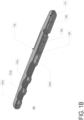
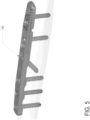
- FIGS. 1A-E shown are various views of a bone plate (100) according to one embodiment of the present invention adapted to perform an ulnar shortening osteotomy.
- the bone plate shown is used to guide the surgeon, together with the cutting guide shown in FIG. 2 , to precisely cut the desired length from the ulnar bone, to rejoin the two ends of the bone, and to stabilize the rejoined bone ends in compression to promote their subsequent fusion.
- the bone plate (100) comprises a substantially elongated metal plate having tapered distal (101) and proximal (102) ends.
- the bone plate (100) further comprises a bone contacting side (103) and an opposite side (104) a left sidewall (110) and a right sidewall (111).
- the bone contacting side has a generally cylindrical concave shape which generally conforms, or can be bent to conform, the contour of the bone to be treated.
- the bone plate also includes a proximal elongated slot (105) and a distal elongated slot (106) which can be threaded or unthreaded.
- the bone plate (100) further comprises one or more threaded or unthreaded bone screw holes (107a-d,) suitable for cortical bone screws or pegs.
- bone screw holes may be adapted for installation of bone screws substantially normal to the bone contacting surface, while others (107d) may be adapted for installation of oblique screws.
- Oblique screws are particularly useful to apply additional compression to rejoined bone ends that have been cut at an oblique angle where the screw can be inserted substantially normal to the angle of the cut.
- a recess (109) Disposed on the opposing side (104) of bone plate (100) is a recess (109) adapted to receive the tip of a reduction forceps.
- a left track (112) and a right track (113) Located respectively in the left and right sidewalls (110,111) of bone plate (100) are a left track (112) and a right track (113) extending longitudinally along the length of bone plate (100).
- Tracks (112,113) extend proximally from a track limit point (119).
- the left and right tracks (112,113) are mirror images and substantially identical with symmetrical placement along the left and right walls (110,111) respectively. However, this is not necessary as long as the tracks are adapted to engage corresponding features (shown in figures described below) in cutting guide (200). As shown in detail in FIG.
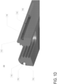
- the track comprises an upper bounding wall (114) and a lower bounding wall (115).
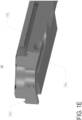
- Lower bounding wall (115) extends for the entire length of the track while the upper bounding wall (114) only extends partially from the distal end of the track (119) to a location (117) before the proximal end of the track (118) creating an overhead entry (116) to the track.
- FIG. 1D shows a cross-section of bone plate (100) at a location where the tracks are bound by the upper and lower bounding walls (114, 115).
- FIG. 1E shows a cross-section of bone plate (100) at a location where the tracks are bound only by the lower bounding wall (115).
- Laser etched, or otherwise affixed to the opposing side (104) of the bone plate (100) is a series of indicia (120), including a zero-mark line (121) used to measure the proximal-distal movement of the cutting guide (200) relative to the bone plate (100)
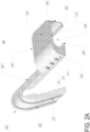
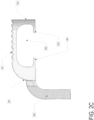
- FIGS. 2A-C shown are various views of a bone cutting guide (200) adapted to perform an ulnar shortening osteotomy.
- the shown example of bone cutting guide (200) is adapted to cooperate with the bone plate (100) shown in FIGS. 1A-E .
- the bone cutting guide (200) comprises a handling feature (201) which can optionally be textured and oriented in a generally horizontal plane having proximal and distal edges (212,213). Extending downwardly from the left and right side of the handling feature (201) respectively are guide walls (202,203) which terminate in left (204) and right (205) horizontal guide blades.
- the left and right guide blades (204,205) are situated on the bone cutting guide (200) so as to precisely mate with the left and right tracks (112,113) of the bone plate (100).
- the interior space (206) bounded by the handling feature (201), guide walls (202,203) and the left and right guide blades (204,205) is sufficiently large to permit the bone plate (100), once the guide blades (204,205) are mated to the tracks (112,113), to glide in the proximal-distal direction without interference from the bone cutting guide (200).
- the distal movement of the cutting guide (200) will be constrained by the track limit point (119).
- the cutting guide further comprises an arm (207) which extends distally from one side (left or right) of the handling feature (201), or from the guide walls (202 or 203) as shown in the illustrated embodiment. Extending downward from the distal end of the arm is a flange (208) which incorporates a cutting blade slot (209).
- the blade slot (209) is adapted to guide a blade from standard oscillating surgical saw or other similar bonecutting device (not shown) to make a set of precise parallel bone cuts in the target bone.
- the flange (208) may optionally comprise a secondary blade slot (210) parallel to, and located proximal of, blade slot (209) to permit for the making of additional cuts at a known offset (in this case 4 mm) from the first cut without requiring sliding of the cutting guide (200) on the bone plate (100).
- additional blade slots may optionally be included on flange (208) to make cuts at different standard offsets from the first cut.
- Cutting guide (200) may also optionally include one or more Kirschner Wire (K-Wire) holes (211) on one or both of the guide walls (202,203). These K-Wire holes (211) are obliquely oriented and adapted to guide K-Wires into the target bone to temporarily lock the position of the cutting guide (200) relative to the target bone. Alternatively, the position of the cutting guide (200) may be locked by using a lock screw or clamp (not shown) between the cutting guide (200) and the bone plate (100).
- K-Wire Kirschner Wire
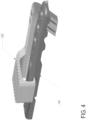
- step 2 the cutting guide (200) is placed directly above bone plate (100) with the guide blades (204,205) oriented downward and the opposite side (104) of bone plate (100) facing upward. Guide blades (204,205) should be aligned with track overhead entries (116).
- step 2 the cutting guide is moved downward until the tracks (204,205) are resting on lower bounding walls (115).
- step 3 the cutting guide (200) is slid distally in relation to bone plate (100) until the distal movement is constrained by the track limit points (119).
- this exemplary illustration demonstrates the cutting guide (200) engaging the bone plate (100) from the overhead position
- the system of the present invention also permits the cutting guide (200) to engage the bone plate (100) from the rear position.
- proximal elongated slot (105) use a drill of appropriate size (and optionally drill guides if using locking screws) to place a cortical screw, of appropriate length, into the proximal long slot (105) in the most proximal position.
- proximal elongated slot (106) use a drill of appropriate size (and optionally drill guides if using locking screws) to place a cortical screw, of appropriate length, into the proximal long slot (106) in the most proximal position.
- cutting guide (200) align and install on bone plate (100), using the procedure previously described, the appropriate cutting guide (200) (transverse (not shown) and oblique ( FIGS 1A-E , 2A-C ) options are available) to the bone plate (100). Position cutting guide (200) such that proximal edge (213) is just distal of the zero-mark line (121). Use two K-Wires to temporarily fix the cutting guide (200) by driving them into the K-Wire holes (211) on the cutting guide (200) and into the bone.
- Each laser etched indicia line (120) on the bone plate (100) corresponds to an additional osteotomy length of 2mm.
- Use two K-Wires to again temporarily fix the cutting guide (200) by driving them into the K-Wire holes (211) on the cutting guide (200) and into the bone.
- the two screws in the proximal and distal elongated slots (105,106) loosen the two screws in the proximal and distal elongated slots (105,106) and place one blade of an appropriately sized forceps into recess (109) and the other blade into the head of one of the loosened screws.
- the other blade of the forceps can be placed adjacent to the opposite side of the head of one of the loosened screws.
- a specialized forceps may be used which has the tip of one blade shaped to mate with recess (109) and the tip of the other blade shaped to mate with either the driver pattern on the head of the screws or with the side of the head of the screws. Using the forceps, reduce and compress the ulnar fragments together until adequate compression is achieved across the osteotomy site. Tighten the two screws loosened previously in this step.
- an oblique lag screw may be placed across the osteotomy interface. Use a drill of appropriate size to place a cortical lag screw, of appropriate length, into the oblique bone screw hole (107d) of the bone plate (100).
Landscapes
- Health & Medical Sciences (AREA)
- Orthopedic Medicine & Surgery (AREA)
- Surgery (AREA)
- Life Sciences & Earth Sciences (AREA)
- Heart & Thoracic Surgery (AREA)
- Veterinary Medicine (AREA)
- Engineering & Computer Science (AREA)
- Biomedical Technology (AREA)
- Nuclear Medicine, Radiotherapy & Molecular Imaging (AREA)
- Medical Informatics (AREA)
- Molecular Biology (AREA)
- Animal Behavior & Ethology (AREA)
- General Health & Medical Sciences (AREA)
- Public Health (AREA)
- Oral & Maxillofacial Surgery (AREA)
- Dentistry (AREA)
- Neurology (AREA)
- Pathology (AREA)
- Surgical Instruments (AREA)
Claims (10)
- Eine Knochenplatte (100), umfassend:eine im Wesentlichen starre Platte, einschließlich eines länglichen Körpers, der ein proximales Ende (102) und ein distales Ende (101) aufweist und eine Längskörperachse definiert;die Platte (100) umfassend eine Knochenkontaktseite (103), eine gegenüberliegende Seite (104), eine linke Seitenwand (110) und eine rechte Seitenwand (111), die sich alle zwischen dem proximalen Ende (102) der Platte und dem distalen Ende (101) der Platte erstrecken, und die alle im Wesentlichen an der Längskörperachse ausgerichtet sind;einen proximalen Längsschlitz (105), der sich durch die Platte (100) zwischen der gegenüberliegenden Seite (104) und der Knochenkontaktseite (103), die sich neben dem proximalen Ende der Platte befindet, erstreckt, wobei der proximale Längsschlitz (105) angepasst ist, um eine Knochenschraube aufzunehmen;einen distalen Längsschlitz (106), der sich durch die Platte (100) zwischen der gegenüberliegenden Seite (104) und der Knochenkontaktseite (103) und neben dem proximalen Längsschlitz (105) erstreckt, sich jedoch in Bezug auf den proximalen Längsschlitz (105) distal auf der Platte (100) befindet, wobei der distale Längsschlitz (106) angepasst ist, um eine Knochenschraube aufzunehmen;ein oder mehrere Knochenschraubenlöcher, die sich durch die Platte (100) zwischen der gegenüberliegenden Seite (104) und der Knochenkontaktseite (103) erstrecken und sich in Bezug auf den distalen Längsschlitz (106) distal auf der Platte (100) befinden, wobei das eine oder die mehreren Knochenschraubenlöcher angepasst sind, um eine Knochenschraube aufzunehmen; eine Aussparung (109) auf der gegenüberliegenden Seite (104) der Platte;eine linke Schiene, die in der linken Seitenwand (110) ausgespart ist, wobei die linke Schiene (112) sich in Längsrichtung zwischen einem Schienengrenzpunkt (119) und dem proximalen Ende (102) der Platte erstreckt, wobei die linke Schiene (112) durch eine obere Begrenzungswand (114) und eine untere Begrenzungswand (115) begrenzt ist, wobei sich die untere Begrenzungswand (115) über die gesamte Länge der linken Schiene (112) erstreckt, während sich die obere Begrenzungswand (114) teilweise von dem distalen Ende der linken Schiene (112) bis zu einer Stelle distal zu dem proximalen Ende der linken Schiene (112) erstreckt;und eine rechte Schiene (113), die in der rechten Seitenwand (111) ausgespart ist, wobei die rechte Schiene (113) sich in Längsrichtung zwischen einem Schienengrenzpunkt (119) und dem proximalen Ende (102) der Platte erstreckt, wobei die rechte Schiene (113) durch eine obere Begrenzungswand und eine untere Begrenzungswand begrenzt ist, wobei sich die untere Begrenzungswand über die gesamte Länge der rechten Schiene (113) erstreckt, während sich die obere Begrenzungswand (114) teilweise von dem distalen Ende (101) der rechten Schiene bis zu einer Stelle distal zu dem proximalen Ende der rechten Schiene (113) erstreckt; wobei die Abschnitte der linken Schiene (112) und der rechten Schiene, die nur durch eine untere Begrenzungswand begrenzt sind, einen von der gegenüberliegenden Seite (104) der Platte aus zugänglichen Überkopf-Eingang zu der linken Schiene (112) und rechten Schiene (113) bereitstellen.
- Knochenplatte (100) nach Anspruch 1, wobei mindestens einer von dem proximalen Längsschlitz (105) und dem distalen Längsschlitz (106) mit einem Gewinde versehen ist.
- Knochenplatte (100) nach Anspruch 1, wobei mindestens einer von dem proximalen Längsschlitz (105) und dem distalen Längsschlitz (106) ohne Gewinde ist.
- Knochenplatte (100) nach Anspruch 1, wobei mindestens eines von dem proximalen Ende (102) der Platte und dem distalen Ende (103) der Platte verjüngt ist.
- Knochenplatte (100) nach Anspruch 1, wobei mindestens ein Abschnitt der Knochenkontaktoberfläche zylindrisch konkav ist.
- Knochenplatte (100) nach Anspruch 1, wobei mindestens eines von dem einen oder den mehreren Knochenschraubenlöchern (107a-d) mit einem Gewinde versehen ist.
- Knochenplatte (100) nach Anspruch 1, wobei mindestens eines von dem einen oder den mehreren Knochenschraubenlöchern (107a-d) ohne Gewinde ist.
- Knochenplatte (100) nach Anspruch 1, wobei mindestens eines von dem einen oder den mehreren Knochenschraubenlöchern (107a-d) eine Schraubenachse definiert, die im Wesentlichen senkrecht zu der Knochenkontaktoberfläche steht.
- Knochenplatte (100) nach Anspruch 1, wobei mindestens eines von dem einen oder den mehreren Knochenschraubenlöchern (107a-d) eine Schraubenachse definiert, die schräg zu der Knochenkontaktoberfläche verläuft.
- Knochenplatte (100) nach Anspruch 1, wobei die Aussparung (109) angepasst ist, um eine Klingenspitze einer Repositionszange aufzunehmen.
Applications Claiming Priority (3)
| Application Number | Priority Date | Filing Date | Title |
|---|---|---|---|
| US201962927325P | 2019-10-29 | 2019-10-29 | |
| EP20882326.0A EP4051136B1 (de) | 2019-10-29 | 2020-10-29 | Osteotomiesystem |
| PCT/US2020/057845 WO2021087033A1 (en) | 2019-10-29 | 2020-10-29 | Osteotomy system and method of use |
Related Parent Applications (2)
| Application Number | Title | Priority Date | Filing Date |
|---|---|---|---|
| EP20882326.0A Division EP4051136B1 (de) | 2019-10-29 | 2020-10-29 | Osteotomiesystem |
| EP20882326.0A Division-Into EP4051136B1 (de) | 2019-10-29 | 2020-10-29 | Osteotomiesystem |
Publications (2)
| Publication Number | Publication Date |
|---|---|
| EP4137076A1 EP4137076A1 (de) | 2023-02-22 |
| EP4137076B1 true EP4137076B1 (de) | 2024-12-04 |
Family
ID=75716319
Family Applications (2)
| Application Number | Title | Priority Date | Filing Date |
|---|---|---|---|
| EP20882326.0A Active EP4051136B1 (de) | 2019-10-29 | 2020-10-29 | Osteotomiesystem |
| EP22194163.6A Active EP4137076B1 (de) | 2019-10-29 | 2020-10-29 | Osteotomiesystem |
Family Applications Before (1)
| Application Number | Title | Priority Date | Filing Date |
|---|---|---|---|
| EP20882326.0A Active EP4051136B1 (de) | 2019-10-29 | 2020-10-29 | Osteotomiesystem |
Country Status (6)
| Country | Link |
|---|---|
| US (2) | US11026698B2 (de) |
| EP (2) | EP4051136B1 (de) |
| JP (1) | JP7499324B2 (de) |
| AU (1) | AU2020376839C1 (de) |
| ES (2) | ES2999104T3 (de) |
| WO (1) | WO2021087033A1 (de) |
Families Citing this family (1)
| Publication number | Priority date | Publication date | Assignee | Title |
|---|---|---|---|---|
| CN117084747B (zh) * | 2023-09-07 | 2025-08-26 | 中国人民解放军陆军军医大学第一附属医院 | 一种转动截骨缩短器 |
Family Cites Families (28)
| Publication number | Priority date | Publication date | Assignee | Title |
|---|---|---|---|---|
| DE1286686B (de) * | 1965-01-16 | 1969-01-09 | Feinmechanik Vorm Jetter & Sch | Chirurgische Vorrichtung zum Zusammenziehen und Fixieren von Knochenbruchstuecken |
| US3866607A (en) * | 1973-08-09 | 1975-02-18 | Environmental Sciences Corp | Bone fracture compression device and method of usage |
| US4811877A (en) * | 1979-10-29 | 1989-03-14 | Amco Corporation | Modular luggage carrier with sliding tie-down bracket stabilized against luggage-securing forces |
| US4929247A (en) | 1988-10-06 | 1990-05-29 | Rayhack John M | Bone compression and distraction device |
| US5042983A (en) * | 1989-10-30 | 1991-08-27 | Rayhack John M | Precision bone cutting guide |
| US5261910A (en) * | 1992-02-19 | 1993-11-16 | Acromed Corporation | Apparatus for maintaining spinal elements in a desired spatial relationship |
| US6916323B2 (en) | 2001-08-21 | 2005-07-12 | Depuy Products, Inc. | Method and apparatus for percutaneously securing a bone screw and a bone plate to a bone of a patient |
| JP2003180704A (ja) | 2001-12-18 | 2003-07-02 | Homuzu Giken:Kk | 大腿骨の接合具 |
| US8652142B2 (en) | 2006-04-28 | 2014-02-18 | Acumed Llc | Osteotomy systems |
| KR101081269B1 (ko) * | 2002-11-19 | 2011-11-08 | 어큠드 엘엘씨 | 조정가능한 본 플레이트 |
| US7540874B2 (en) | 2004-05-27 | 2009-06-02 | Trimed Inc. | Method and device for use in osteotomy |
| US7344538B2 (en) | 2005-03-31 | 2008-03-18 | Depuy Products, Inc. | Mid-foot fixation plate |
| US20070276383A1 (en) | 2006-05-11 | 2007-11-29 | Rayhack L.L.C. | Osteotomy system |
| WO2009055537A1 (en) * | 2007-10-23 | 2009-04-30 | K2M, Inc. | Dynamic cervical plate |
| US20090192549A1 (en) | 2008-01-30 | 2009-07-30 | Ebi, Llc | Bone plating system |
| AT506937B1 (de) * | 2008-11-27 | 2010-01-15 | I T S Gmbh | Vorrichtung zum verkürzen eines länglichen knochens |
| US20100168799A1 (en) * | 2008-12-29 | 2010-07-01 | Schumer Evan D | Ulnar osteotomy plate including increased compression |
| EP2542170B1 (de) | 2010-03-04 | 2018-05-09 | Synthes GmbH | Osteotomiesystem |
| US8523861B2 (en) * | 2010-08-30 | 2013-09-03 | Biomet Manufacturing, Llc | Method and apparatus for osteosynthesis |
| FR2968190B1 (fr) * | 2010-12-01 | 2013-09-27 | D L P Sarl | Equipement pour la mise en compression de deux parties osseuses |
| DE102011075771A1 (de) * | 2011-05-12 | 2012-11-15 | Airbus Operations Gmbh | Vorrichtung zur Befestigung von Sitzen in Passagierkabinen, Sitzschiene, Halteeinrichtung und Verfahren |
| CA2857992C (en) * | 2011-12-09 | 2018-08-14 | Zimmer Gmbh | Orthopedic plate, orthopedic device, method of coupling bone segments, and method of assembling an orthopedic plate |
| US9265542B2 (en) | 2012-06-27 | 2016-02-23 | DePuy Synthes Products, Inc. | Variable angle bone fixation device |
| DE102013104887B4 (de) * | 2013-05-13 | 2021-03-18 | Aap Implantate Ag | Osteosyntheseplatte sowie Segment für eine Osteosyntheseplatte |
| WO2015112991A1 (en) * | 2014-01-27 | 2015-07-30 | Dallis James | Implantable medical device for restoring alignment and stabilizing bone fractures |
| US10245086B2 (en) | 2015-02-18 | 2019-04-02 | Treace Medical Concepts, Inc. | Bone plating kit for foot and ankle applications |
| PT3291751T (pt) | 2015-04-23 | 2023-10-30 | Acumed Llc | Sistema para deformar membros de placa no osso |
| US10687873B2 (en) * | 2016-08-17 | 2020-06-23 | Globus Medical Inc. | Stabilization systems |
-
2020
- 2020-10-28 US US17/082,862 patent/US11026698B2/en active Active
- 2020-10-29 JP JP2022525103A patent/JP7499324B2/ja active Active
- 2020-10-29 AU AU2020376839A patent/AU2020376839C1/en active Active
- 2020-10-29 WO PCT/US2020/057845 patent/WO2021087033A1/en not_active Ceased
- 2020-10-29 ES ES20882326T patent/ES2999104T3/es active Active
- 2020-10-29 EP EP20882326.0A patent/EP4051136B1/de active Active
- 2020-10-29 EP EP22194163.6A patent/EP4137076B1/de active Active
- 2020-10-29 ES ES22194163T patent/ES3006996T3/es active Active
-
2021
- 2021-05-19 US US17/324,815 patent/US11701129B2/en active Active
Also Published As
| Publication number | Publication date |
|---|---|
| AU2020376839C1 (en) | 2025-05-01 |
| US20210137534A1 (en) | 2021-05-13 |
| EP4137076A1 (de) | 2023-02-22 |
| ES2999104T3 (en) | 2025-02-24 |
| ES3006996T3 (en) | 2025-03-19 |
| EP4051136B1 (de) | 2024-09-18 |
| US11026698B2 (en) | 2021-06-08 |
| EP4051136A4 (de) | 2023-11-29 |
| CA3157987A1 (en) | 2021-05-06 |
| JP7499324B2 (ja) | 2024-06-13 |
| WO2021087033A1 (en) | 2021-05-06 |
| US20210267606A1 (en) | 2021-09-02 |
| US11701129B2 (en) | 2023-07-18 |
| AU2020376839A1 (en) | 2022-04-21 |
| AU2020376839B2 (en) | 2024-12-19 |
| EP4051136A1 (de) | 2022-09-07 |
| JP2023500484A (ja) | 2023-01-06 |
Similar Documents
| Publication | Publication Date | Title |
|---|---|---|
| AU2023266377B2 (en) | Bone positioning and preparing guide systems and methods | |
| US20220287747A1 (en) | Bone plating kit for foot and ankle applications | |
| US10888335B2 (en) | Bone cutting guide systems and methods | |
| AU2019325879B2 (en) | Guidance system for hallux valgus correction | |
| EP2906129B1 (de) | Knochenverkürzungsvorrichtung | |
| AU2008356192B2 (en) | Intramedullary device assembly and associated method | |
| US20120053587A1 (en) | Method and apparatus for osteosynthesis | |
| US20210259749A1 (en) | A device and method for fixation of bone fragments in an osteotomy procedure | |
| US12186001B2 (en) | Targeting guide | |
| EP4104776A2 (de) | Minimal invasiver chirurgischer osteotomiefragmentschieber, stabilisator und zielgerät | |
| EP1976442A2 (de) | Anordnungen zur bruchreduktion | |
| EP4051136B1 (de) | Osteotomiesystem | |
| CA3157987C (en) | Osteotomy system and method of use | |
| US11849962B2 (en) | Cutting guide with protective insert | |
| EP4534025A1 (de) | Schablone zur bruchreduktion und positionierung von platten bei der osteosynthese | |
| US12440251B2 (en) | Small bone internal fixation system for orthopedic surgery | |
| US20250064458A1 (en) | Patient-Specific Instruments For Performing Bone Cuts |
Legal Events
| Date | Code | Title | Description |
|---|---|---|---|
| PUAI | Public reference made under article 153(3) epc to a published international application that has entered the european phase |
Free format text: ORIGINAL CODE: 0009012 |
|
| STAA | Information on the status of an ep patent application or granted ep patent |
Free format text: STATUS: REQUEST FOR EXAMINATION WAS MADE |
|
| 17P | Request for examination filed |
Effective date: 20220906 |
|
| AC | Divisional application: reference to earlier application |
Ref document number: 4051136 Country of ref document: EP Kind code of ref document: P |
|
| AK | Designated contracting states |
Kind code of ref document: A1 Designated state(s): AL AT BE BG CH CY CZ DE DK EE ES FI FR GB GR HR HU IE IS IT LI LT LU LV MC MK MT NL NO PL PT RO RS SE SI SK SM TR |
|
| GRAP | Despatch of communication of intention to grant a patent |
Free format text: ORIGINAL CODE: EPIDOSNIGR1 |
|
| STAA | Information on the status of an ep patent application or granted ep patent |
Free format text: STATUS: GRANT OF PATENT IS INTENDED |
|
| INTG | Intention to grant announced |
Effective date: 20240902 |
|
| GRAS | Grant fee paid |
Free format text: ORIGINAL CODE: EPIDOSNIGR3 |
|
| GRAA | (expected) grant |
Free format text: ORIGINAL CODE: 0009210 |
|
| STAA | Information on the status of an ep patent application or granted ep patent |
Free format text: STATUS: THE PATENT HAS BEEN GRANTED |
|
| P01 | Opt-out of the competence of the unified patent court (upc) registered |
Free format text: CASE NUMBER: APP_54211/2024 Effective date: 20241001 |
|
| AC | Divisional application: reference to earlier application |
Ref document number: 4051136 Country of ref document: EP Kind code of ref document: P |
|
| AK | Designated contracting states |
Kind code of ref document: B1 Designated state(s): AL AT BE BG CH CY CZ DE DK EE ES FI FR GB GR HR HU IE IS IT LI LT LU LV MC MK MT NL NO PL PT RO RS SE SI SK SM TR |
|
| REG | Reference to a national code |
Ref country code: CH Ref legal event code: EP |
|
| REG | Reference to a national code |
Ref country code: DE Ref legal event code: R096 Ref document number: 602020042828 Country of ref document: DE |
|
| REG | Reference to a national code |
Ref country code: IE Ref legal event code: FG4D |
|
| REG | Reference to a national code |
Ref country code: ES Ref legal event code: FG2A Ref document number: 3006996 Country of ref document: ES Kind code of ref document: T3 Effective date: 20250319 |
|
| REG | Reference to a national code |
Ref country code: LT Ref legal event code: MG9D |
|
| REG | Reference to a national code |
Ref country code: NL Ref legal event code: MP Effective date: 20241204 |
|
| PG25 | Lapsed in a contracting state [announced via postgrant information from national office to epo] |
Ref country code: HR Free format text: LAPSE BECAUSE OF FAILURE TO SUBMIT A TRANSLATION OF THE DESCRIPTION OR TO PAY THE FEE WITHIN THE PRESCRIBED TIME-LIMIT Effective date: 20241204 |
|
| PG25 | Lapsed in a contracting state [announced via postgrant information from national office to epo] |
Ref country code: FI Free format text: LAPSE BECAUSE OF FAILURE TO SUBMIT A TRANSLATION OF THE DESCRIPTION OR TO PAY THE FEE WITHIN THE PRESCRIBED TIME-LIMIT Effective date: 20241204 |
|
| PG25 | Lapsed in a contracting state [announced via postgrant information from national office to epo] |
Ref country code: BG Free format text: LAPSE BECAUSE OF FAILURE TO SUBMIT A TRANSLATION OF THE DESCRIPTION OR TO PAY THE FEE WITHIN THE PRESCRIBED TIME-LIMIT Effective date: 20241204 |
|
| PG25 | Lapsed in a contracting state [announced via postgrant information from national office to epo] |
Ref country code: NO Free format text: LAPSE BECAUSE OF FAILURE TO SUBMIT A TRANSLATION OF THE DESCRIPTION OR TO PAY THE FEE WITHIN THE PRESCRIBED TIME-LIMIT Effective date: 20250304 |
|
| PG25 | Lapsed in a contracting state [announced via postgrant information from national office to epo] |
Ref country code: GR Free format text: LAPSE BECAUSE OF FAILURE TO SUBMIT A TRANSLATION OF THE DESCRIPTION OR TO PAY THE FEE WITHIN THE PRESCRIBED TIME-LIMIT Effective date: 20250305 Ref country code: LV Free format text: LAPSE BECAUSE OF FAILURE TO SUBMIT A TRANSLATION OF THE DESCRIPTION OR TO PAY THE FEE WITHIN THE PRESCRIBED TIME-LIMIT Effective date: 20241204 |
|
| PG25 | Lapsed in a contracting state [announced via postgrant information from national office to epo] |
Ref country code: RS Free format text: LAPSE BECAUSE OF FAILURE TO SUBMIT A TRANSLATION OF THE DESCRIPTION OR TO PAY THE FEE WITHIN THE PRESCRIBED TIME-LIMIT Effective date: 20250304 |
|
| PG25 | Lapsed in a contracting state [announced via postgrant information from national office to epo] |
Ref country code: NL Free format text: LAPSE BECAUSE OF FAILURE TO SUBMIT A TRANSLATION OF THE DESCRIPTION OR TO PAY THE FEE WITHIN THE PRESCRIBED TIME-LIMIT Effective date: 20241204 |
|
| REG | Reference to a national code |
Ref country code: AT Ref legal event code: MK05 Ref document number: 1747286 Country of ref document: AT Kind code of ref document: T Effective date: 20241204 |
|
| PG25 | Lapsed in a contracting state [announced via postgrant information from national office to epo] |
Ref country code: SM Free format text: LAPSE BECAUSE OF FAILURE TO SUBMIT A TRANSLATION OF THE DESCRIPTION OR TO PAY THE FEE WITHIN THE PRESCRIBED TIME-LIMIT Effective date: 20241204 |
|
| PG25 | Lapsed in a contracting state [announced via postgrant information from national office to epo] |
Ref country code: PL Free format text: LAPSE BECAUSE OF FAILURE TO SUBMIT A TRANSLATION OF THE DESCRIPTION OR TO PAY THE FEE WITHIN THE PRESCRIBED TIME-LIMIT Effective date: 20241204 |
|
| PG25 | Lapsed in a contracting state [announced via postgrant information from national office to epo] |
Ref country code: IS Free format text: LAPSE BECAUSE OF FAILURE TO SUBMIT A TRANSLATION OF THE DESCRIPTION OR TO PAY THE FEE WITHIN THE PRESCRIBED TIME-LIMIT Effective date: 20250404 |
|
| PG25 | Lapsed in a contracting state [announced via postgrant information from national office to epo] |
Ref country code: PT Free format text: LAPSE BECAUSE OF FAILURE TO SUBMIT A TRANSLATION OF THE DESCRIPTION OR TO PAY THE FEE WITHIN THE PRESCRIBED TIME-LIMIT Effective date: 20250404 |
|
| PG25 | Lapsed in a contracting state [announced via postgrant information from national office to epo] |
Ref country code: EE Free format text: LAPSE BECAUSE OF FAILURE TO SUBMIT A TRANSLATION OF THE DESCRIPTION OR TO PAY THE FEE WITHIN THE PRESCRIBED TIME-LIMIT Effective date: 20241204 |
|
| PG25 | Lapsed in a contracting state [announced via postgrant information from national office to epo] |
Ref country code: AT Free format text: LAPSE BECAUSE OF FAILURE TO SUBMIT A TRANSLATION OF THE DESCRIPTION OR TO PAY THE FEE WITHIN THE PRESCRIBED TIME-LIMIT Effective date: 20241204 Ref country code: RO Free format text: LAPSE BECAUSE OF FAILURE TO SUBMIT A TRANSLATION OF THE DESCRIPTION OR TO PAY THE FEE WITHIN THE PRESCRIBED TIME-LIMIT Effective date: 20241204 |
|
| PG25 | Lapsed in a contracting state [announced via postgrant information from national office to epo] |
Ref country code: SK Free format text: LAPSE BECAUSE OF FAILURE TO SUBMIT A TRANSLATION OF THE DESCRIPTION OR TO PAY THE FEE WITHIN THE PRESCRIBED TIME-LIMIT Effective date: 20241204 |
|
| PG25 | Lapsed in a contracting state [announced via postgrant information from national office to epo] |
Ref country code: CZ Free format text: LAPSE BECAUSE OF FAILURE TO SUBMIT A TRANSLATION OF THE DESCRIPTION OR TO PAY THE FEE WITHIN THE PRESCRIBED TIME-LIMIT Effective date: 20241204 |
|
| PG25 | Lapsed in a contracting state [announced via postgrant information from national office to epo] |
Ref country code: IT Free format text: LAPSE BECAUSE OF FAILURE TO SUBMIT A TRANSLATION OF THE DESCRIPTION OR TO PAY THE FEE WITHIN THE PRESCRIBED TIME-LIMIT Effective date: 20241204 |
|
| REG | Reference to a national code |
Ref country code: DE Ref legal event code: R097 Ref document number: 602020042828 Country of ref document: DE |
|
| PG25 | Lapsed in a contracting state [announced via postgrant information from national office to epo] |
Ref country code: SE Free format text: LAPSE BECAUSE OF FAILURE TO SUBMIT A TRANSLATION OF THE DESCRIPTION OR TO PAY THE FEE WITHIN THE PRESCRIBED TIME-LIMIT Effective date: 20241204 |
|
| PG25 | Lapsed in a contracting state [announced via postgrant information from national office to epo] |
Ref country code: DK Free format text: LAPSE BECAUSE OF FAILURE TO SUBMIT A TRANSLATION OF THE DESCRIPTION OR TO PAY THE FEE WITHIN THE PRESCRIBED TIME-LIMIT Effective date: 20241204 |
|
| PLBE | No opposition filed within time limit |
Free format text: ORIGINAL CODE: 0009261 |
|
| STAA | Information on the status of an ep patent application or granted ep patent |
Free format text: STATUS: NO OPPOSITION FILED WITHIN TIME LIMIT |
|
| REG | Reference to a national code |
Ref country code: CH Ref legal event code: L10 Free format text: ST27 STATUS EVENT CODE: U-0-0-L10-L00 (AS PROVIDED BY THE NATIONAL OFFICE) Effective date: 20251015 |
|
| REG | Reference to a national code |
Ref country code: CH Ref legal event code: U11 Free format text: ST27 STATUS EVENT CODE: U-0-0-U10-U11 (AS PROVIDED BY THE NATIONAL OFFICE) Effective date: 20251101 |
|
| 26N | No opposition filed |
Effective date: 20250905 |
|
| PGFP | Annual fee paid to national office [announced via postgrant information from national office to epo] |
Ref country code: LU Payment date: 20251027 Year of fee payment: 6 |
|
| PGFP | Annual fee paid to national office [announced via postgrant information from national office to epo] |
Ref country code: DE Payment date: 20251029 Year of fee payment: 6 |
|
| PGFP | Annual fee paid to national office [announced via postgrant information from national office to epo] |
Ref country code: GB Payment date: 20251027 Year of fee payment: 6 |
|
| PGFP | Annual fee paid to national office [announced via postgrant information from national office to epo] |
Ref country code: MC Payment date: 20251003 Year of fee payment: 6 |
|
| PGFP | Annual fee paid to national office [announced via postgrant information from national office to epo] |
Ref country code: FR Payment date: 20251027 Year of fee payment: 6 |
|
| PGFP | Annual fee paid to national office [announced via postgrant information from national office to epo] |
Ref country code: CH Payment date: 20251101 Year of fee payment: 6 |
|
| PGFP | Annual fee paid to national office [announced via postgrant information from national office to epo] |
Ref country code: IE Payment date: 20251027 Year of fee payment: 6 |
|
| PGFP | Annual fee paid to national office [announced via postgrant information from national office to epo] |
Ref country code: ES Payment date: 20251103 Year of fee payment: 6 |