EP4137006A1 - Linear motion mechanism, drawer assembly, and storage cabinet - Google Patents
Linear motion mechanism, drawer assembly, and storage cabinet Download PDFInfo
- Publication number
- EP4137006A1 EP4137006A1 EP21931350.9A EP21931350A EP4137006A1 EP 4137006 A1 EP4137006 A1 EP 4137006A1 EP 21931350 A EP21931350 A EP 21931350A EP 4137006 A1 EP4137006 A1 EP 4137006A1
- Authority
- EP
- European Patent Office
- Prior art keywords
- sliding rail
- flexible cable
- linear motion
- stage sliding
- rotating wheel
- Prior art date
- Legal status (The legal status is an assumption and is not a legal conclusion. Google has not performed a legal analysis and makes no representation as to the accuracy of the status listed.)
- Granted
Links
Images


Classifications
-
- A—HUMAN NECESSITIES
- A47—FURNITURE; DOMESTIC ARTICLES OR APPLIANCES; COFFEE MILLS; SPICE MILLS; SUCTION CLEANERS IN GENERAL
- A47B—TABLES; DESKS; OFFICE FURNITURE; CABINETS; DRAWERS; GENERAL DETAILS OF FURNITURE
- A47B88/00—Drawers for tables, cabinets or like furniture; Guides for drawers
- A47B88/40—Sliding drawers; Slides or guides therefor
-
- A—HUMAN NECESSITIES
- A47—FURNITURE; DOMESTIC ARTICLES OR APPLIANCES; COFFEE MILLS; SPICE MILLS; SUCTION CLEANERS IN GENERAL
- A47B—TABLES; DESKS; OFFICE FURNITURE; CABINETS; DRAWERS; GENERAL DETAILS OF FURNITURE
- A47B88/00—Drawers for tables, cabinets or like furniture; Guides for drawers
- A47B88/40—Sliding drawers; Slides or guides therefor
- A47B88/453—Actuated drawers
- A47B88/457—Actuated drawers operated by electrically-powered actuation means
-
- A—HUMAN NECESSITIES
- A47—FURNITURE; DOMESTIC ARTICLES OR APPLIANCES; COFFEE MILLS; SPICE MILLS; SUCTION CLEANERS IN GENERAL
- A47B—TABLES; DESKS; OFFICE FURNITURE; CABINETS; DRAWERS; GENERAL DETAILS OF FURNITURE
- A47B88/00—Drawers for tables, cabinets or like furniture; Guides for drawers
- A47B88/40—Sliding drawers; Slides or guides therefor
- A47B88/453—Actuated drawers
-
- A—HUMAN NECESSITIES
- A47—FURNITURE; DOMESTIC ARTICLES OR APPLIANCES; COFFEE MILLS; SPICE MILLS; SUCTION CLEANERS IN GENERAL
- A47B—TABLES; DESKS; OFFICE FURNITURE; CABINETS; DRAWERS; GENERAL DETAILS OF FURNITURE
- A47B67/00—Chests; Dressing-tables; Medicine cabinets or the like; Cabinets characterised by the arrangement of drawers
- A47B67/04—Chests of drawers; Cabinets characterised by the arrangement of drawers
-
- A—HUMAN NECESSITIES
- A47—FURNITURE; DOMESTIC ARTICLES OR APPLIANCES; COFFEE MILLS; SPICE MILLS; SUCTION CLEANERS IN GENERAL
- A47B—TABLES; DESKS; OFFICE FURNITURE; CABINETS; DRAWERS; GENERAL DETAILS OF FURNITURE
- A47B88/00—Drawers for tables, cabinets or like furniture; Guides for drawers
- A47B88/40—Sliding drawers; Slides or guides therefor
- A47B88/49—Sliding drawers; Slides or guides therefor with double extensible guides or parts
-
- A—HUMAN NECESSITIES
- A47—FURNITURE; DOMESTIC ARTICLES OR APPLIANCES; COFFEE MILLS; SPICE MILLS; SUCTION CLEANERS IN GENERAL
- A47F—SPECIAL FURNITURE, FITTINGS, OR ACCESSORIES FOR SHOPS, STOREHOUSES, BARS, RESTAURANTS OR THE LIKE; PAYING COUNTERS
- A47F3/00—Show cases or show cabinets
- A47F3/06—Show cases or show cabinets with movable or removable shelves or receptacles
- A47F3/063—Show cases or show cabinets with movable or removable shelves or receptacles with pull-out receptacles, e.g. drawers
-
- F—MECHANICAL ENGINEERING; LIGHTING; HEATING; WEAPONS; BLASTING
- F25—REFRIGERATION OR COOLING; COMBINED HEATING AND REFRIGERATION SYSTEMS; HEAT PUMP SYSTEMS; MANUFACTURE OR STORAGE OF ICE; LIQUEFACTION SOLIDIFICATION OF GASES
- F25D—REFRIGERATORS; COLD ROOMS; ICE-BOXES; COOLING OR FREEZING APPARATUS NOT OTHERWISE PROVIDED FOR
- F25D25/00—Charging, supporting, and discharging the articles to be cooled
- F25D25/02—Charging, supporting, and discharging the articles to be cooled by shelves
- F25D25/024—Slidable shelves
- F25D25/025—Drawers
-
- A—HUMAN NECESSITIES
- A47—FURNITURE; DOMESTIC ARTICLES OR APPLIANCES; COFFEE MILLS; SPICE MILLS; SUCTION CLEANERS IN GENERAL
- A47B—TABLES; DESKS; OFFICE FURNITURE; CABINETS; DRAWERS; GENERAL DETAILS OF FURNITURE
- A47B88/00—Drawers for tables, cabinets or like furniture; Guides for drawers
- A47B88/40—Sliding drawers; Slides or guides therefor
- A47B88/44—Sequencing or synchronisation of drawer slides or functional units
- A47B88/447—Simultaneous movement of rails within drawer slides, i.e. with a coordination of movement with all rail elements moving at the same time
Definitions
- the present application relates to the technical field of linear motion technologies, in particular to a linear motion mechanism, a drawer assembly, and a storage cabinet.
- Linear motion mechanisms are applied in many products.
- a linear motion mechanism should be installed between the drawer body and the box body.
- the linear motion mechanism in the related art can only switch states under an operation of an external force. Even if the linear motion mechanism of a small number of existing products can automatically switch states, it will add a lot of additional special members, which will lead to large space occupation, complex structure, high cost and inconvenient assembly and disassembly of the linear motion mechanism.
- an objective of the present application is to solve at least one of the problems existing in the related art.
- the present application provides a linear motion mechanism, which only needs to be added with a rotating wheel, a rotating driving member and a pulley to operate automatically (where the pulley includes a fixed pulley and can further include a movable pulley, and the fixed pulley refers to at least one of a first fixed pulley, a second fixed pulley, and a third fixed pulley in the absence of specific limitations), and thus occupies a small space and has a simple structure without greatly increasing a preparation cost of the linear motion mechanism, and can be assembled or disassembled conveniently.
- the present application further provides a drawer assembly.
- the present application further provides a storage cabinet.
- the linear motion mechanism only needs to be added with a rotating wheel, a rotating driving member and a pulley to operate automatically (where the pulley includes a fixed pulley and can further include a movable pulley, and the fixed pulley refers to at least one of a first fixed pulley, a second fixed pulley, and a third fixed pulley in the absence of specific limitations), and thus occupies a small space and has a simple structure without greatly increasing the preparation cost of the linear motion mechanism.
- the assembly and disassembly of the rotating wheel only involves the rotating driving member and the pulley, the assembly and disassembly are more convenient.
- a number of intermediate sliding rails are provided between the first-stage sliding rail and the guiding rail, and the first-stage sliding rail is installed on the guiding rail through the intermediate sliding rails, the intermediate sliding rail is provided with a movable pulley, and the flexible cable wraps the first fixed pulley and the movable pulley in sequence.
- the linear motion mechanism further includes:
- the linear motion mechanism further includes: a sliding block, fixed on the first-stage sliding rail and configured to perform linear motion along the second-stage sliding rail, and fixedly connected to the flexible cable segment on the two sides of the rotating wheel.
- the sliding block is fixed at a back end of the first-stage sliding rail along an extension direction of the first-stage sliding rail relative to the second-stage sliding rail.
- the first movable pulley and the second movable pulley are respectively provided at two ends of the second-stage sliding rail.
- the flexible cable includes:
- the rotating wheel is installed on the installation member.
- the rotating wheel is provided correspondingly to the first fixed pulley, the first movable pulley and the second movable pulley, a diameter of the rotating wheel is larger than diameters of the first fixed pulley, the first movable pulley and the second movable pulley.
- the linear motion mechanism further includes:
- the rotating wheel is a belt wheel
- the flexible cable is a belt matching with the belt wheel
- the drawer assembly provided by the embodiments of the present application includes a drawer body, and further includes the linear motion mechanism mentioned above, where the drawer body is fixed on a first-stage pulley.
- the rotating wheel is driven to rotate by the rotating driving member, and the flexible cable is led to move, to make the first-stage sliding rail slide relative to the sliding rail.
- the drawer body When the drawer body is installed on the first-stage sliding rail, the drawer body can move relative to the installation member so that the drawer can be pulled automatically.
- the storage cabinet provided by the embodiments of the present application includes a box body and a drawer body and/or a shelf provided in the box body, and further includes the linear motion mechanism mentioned above, where the linear motion mechanism is provided on at least one side of the drawer body and/or shelf, the drawer body and/or shelf are fixed on the first-stage sliding rail, and the installation member is fixed on the box body.
- the drawer body and/or shelf can be pulled automatically, to facilitate the taking and placing of objects.
- the linear motion mechanism between the drawer body and/or shelf occupies a small space and has a simple structure, thereby hardly occupying additional space inside the box body.
- the preparation cost of the linear motion mechanism is low and is convenient to be assembled and disassembled, which has high applicability, and can be applied to various products such as refrigerators, wardrobes, and display cabinets.
- the first-stage sliding rail and the installation member are provided along a height direction of the storage cabinet in sequence, and the first-stage sliding rail is fixed with a side wall of the drawer body or a side wall of the shelf.
- the first-stage sliding rail and the installation member are provided sequentially along a width direction of the storage cabinet, and the first-stage sliding rail is fixed with a bottom plate of the drawer body or a bottom plate of the shelf.
- the rotating wheel is installed on an inner side of the storage cabinet.
- the storage cabinet can be a refrigerator, a retail cabinet or a display cabinet.
- 1 rotating wheel
- 2 flexible cable
- 201 first flexible cable segment
- 202 second flexible cable segment
- 203 third flexible cable segment
- 3 installation member
- 301 guiding rail
- 4 first-stage sliding rail
- 5 second-stage sliding rail
- 6 first fixed pulley
- 7 sliding block
- 8 first movable pulley
- 9 second movable pulley
- 10 second fixed pulley.
- connection to and “connected” shall be understood broadly, for example, it may be either fixedly connected or detachably connected, or can be integrated; it may be either mechanically connected, or electrically connected; it may be either directly connected, or indirectly connected through an intermediate medium.
- connection to and “connected” shall be understood broadly, for example, it may be either fixedly connected or detachably connected, or can be integrated; it may be either mechanically connected, or electrically connected; it may be either directly connected, or indirectly connected through an intermediate medium.
- a first feature is "on” or “under” a second feature can refer to that the first feature is directly contacted with the second feature, or the first feature is indirectly contacted with the second feature through an intermediate medium.
- the first feature is "on”, “above” and “over” the second feature can refer to that the first feature is directly above or obliquely above the second feature, or simply refer to that the stage height of the first feature is higher than that of the second feature.
- the first feature is "under”, “below” and “beneath” the second feature can refer to that the first feature is directly below or obliquely below the second feature, or simply refer to that the stage height of the first feature is lower than that of the second feature.
- the linear motion mechanism includes a rotating wheel 1, a rotating driving member (not shown in the figures), an installation member 3 and a first-stage sliding rail 4.
- the rotating wheel 1 is wrapped by a flexible cable 2, where flexible cable 2 is configured to move as the rotating wheel 1 rotating, and the flexible cable 2 includes cable segments on two sides of the rotating wheel 1.
- the rotating driving member is connected with the rotating wheel 1, and is configured to drive the rotating wheel 1 to rotate.
- the installation member 3 is provided with a guiding rail 301, and the installation member 3 is provided with a first fixed pulley 6.
- the first-stage sliding rail 4 is configured to slide relative to the guiding rail 301.
- the flexible cable 2 wraps the first fixed pulley 6, and the flexible cable segment of the flexible cable 2 located on two sides of the rotating wheel 1 is connected to the first-stage sliding rail 4.
- the linear motion mechanism only needs to be added with a rotating wheel 1, a rotating driving member and a pulley to operate automatically (where the pulley includes a fixed pulley, and can further include a movable pulley, and the fixed pulley refers to at least one of a first fixed pulley 6, a second fixed pulley 10, and a third fixed pulley in the absence of specific limitations), and thus occupies a small space and has a simple structure without greatly increasing the preparation cost of the linear motion mechanism.
- the assembly and disassembly of the rotating wheel 1 only involves the rotating driving member and the pulley, the assembly and disassembly are more convenient.
- the rotating driving member can lead the rotating wheel 1 to rotate, and then the rotating wheel 1 leads the flexible cable 2 to move.
- the flexible cable 2 wraps the first fixed pulley 6, and the flexible cable segment on two sides of the rotating wheel 1 is connected to the first-stage sliding rail 4, the flexible cable 2 can lead the first-stage sliding rail 4 to move linearly relative to the guiding rail 301.
- the first-stage sliding rail 4 performs linear motion in different directions relative to the guiding rail 301.
- FIG. 1 when the rotating wheel 1 rotates clockwise, the flexible cable 2 leads the first-stage sliding rail 4 to move towards a right side of FIG. 1 relative to the guiding rail 301.
- the flexible cable 2 leads the first-stage sliding rail 4 to move towards a left side of FIG. 1 relative to the guiding rail 301.
- the function of the linear motion mechanism is to make a certain point on the mechanism move accurately or approximately linearly. That is, the motion of the linear motion mechanism here includes approximate linear motion.
- the motion of the flexible cable 2 will only lead the first fixed pulley 6 to rotate without the changing spatial position of the first fixed pulley 6.
- the structural form of guiding rail 301 is not limited.
- the guiding rail 301 can include a guiding groove, and then the first-stage sliding rail 4 can move along an extension direction of the guiding groove; or, the guiding rail 301 can include a guiding protrusion, and then the first-stage sliding rail 4 can move along the extension direction of the guiding protrusion.
- the guiding rail 301 can be integrally formed on the installation member 3 or can be an individual member fixed to the installation member 3.
- the structural form of the first-stage sliding rail 4 is not limited, as long as it can form a guiding matching with the guiding rail 301, the first-stage sliding rail 4 can move linearly or approximately linearly relative to the guiding rail 301.
- the first-stage sliding rail 4 and the guiding rail 301 can be matching by a matching protrusion and groove, or a sliding member such as a pulley can be provided between the sliding rail and the guiding rail 301, and then the first-stage sliding rail 4 and the guiding rail 301 are matched by the sliding member.
- the first-stage sliding rail 4 can be an individual member, and can also be formed in a drawer, a shelf board, or the like.
- the drawer or shelf board configured to be installed on the guiding rail 301 can be taken as a sliding rail 4.
- a second-stage sliding rail 5 and a third-stage sliding rail can further be installed between the first-stage sliding rail 4 and the guiding rail 301.
- the first-stage sliding rail 4 is installed on the sliding rail through the second-stage sliding rail 5 and the third-stage sliding rail instead of being directly installed on the guiding rail 301.
- An intermediate sliding rail can be provided between the first sliding rail 4 and the guiding rail 301, and the intermediate sliding rail is provided with a movable pulley, the flexible cable wraps the first fixed pulley 6 and the movable pulley (in the absence of special limitations, the movable pulley refers to a first movable pulley 8 and a second movable pulley 9 provided on the second-stage sliding rail 5, or it further includes movable pulleys provided on other intermediate sliding rails when more intermediate sliding rails are included), so that the first-stage sliding rail 4 moves relative to the intermediate sliding rail, and the intermediate sliding rail moves relative to the guiding rail 301.
- the number of intermediate sliding rails is not limited.
- the intermediate sliding rail is a second-stage sliding rail 5; when there is two intermediate sliding rails, the intermediate sliding rails includes a second-stage sliding rail 5 and a third-stage sliding rail; and when there is three intermediate sliding rails, the intermediate sliding rail includes a second-stage sliding rail 5, a third-stage sliding rail and a fourth-stage sliding rail; and so on.
- the first-stage sliding rail 4 is installed on the sliding rail through the intermediate sliding rails such as the second-stage sliding rail 5 and the third-stage sliding rail instead of being directly installed on the guiding rail 301.
- the intermediate sliding rail including the second-stage sliding rail 5 is taken as an example.
- the second-stage sliding rail 5 is installed on the guiding rail 301 and is configured to slide along the guiding rail 301, and the second-stage sliding rail 5 is provided with the first movable pulley 8 and the second movable pulley 9.
- the first-stage sliding rail 4 is provided on the second-stage sliding rail 5 and is configured to move relative to the second-stage sliding rail 5.
- the flexible cable 2 wraps the first fixed pulley 6, the first movable pulley 8 and the second movable pulley 9 in sequence.
- the linear motion mechanism when the linear motion mechanism includes both the first-stage sliding rail 4 and the second-stage sliding rail 5, the linear motion mechanism can perform second-stage telescopic motion, which corresponds to a third-stage linear motion.
- the linear motion mechanism can further include a third-stage sliding rail, a fourth-stage sliding rail, a fifth-stage sliding rail or the like (the sliding rail refers to at least one of the first-stage sliding rail 4, second-stage sliding rail 5, third-stage sliding rail and the like.), the specific number of the sliding rails is not limited and can be determined according to requirements.
- the first-stage sliding rail 4 refers to the first sliding rail led by the rotation of the rotating driving member to perform telescopic motion.
- the second-stage sliding rail 5 refers to the second sliding rail led by the continuous motion of the rotating driving member to perform telescopic motion when the first sliding rail 4 moves to a limiting position.
- the three-stage slide refers to the third sliding rail led by the continuous motion of the rotating driving member to perform telescopic motion when the two-stage sliding rail 5 moves to the limiting position; and so on.
- the linear motion mechanism further includes a sliding block 7, which is fixed on the first-stage sliding rail 4 and configured to linear motion along the second-stage sliding rail 5, and the sliding block 7 is fixedly connected to the flexible cable segment on two sides of the rotating wheel 1.
- the fixing form between the sliding block 7 and the flexible cable segment is not limited.
- the sliding block 7 and the flexible cable segment can be bound, or the sliding block 7 and the flexible cable segment can be welded.
- the providing of the sliding block 7 can facilitate the assembly between the first-stage sliding rail 4 and the second-stage sliding rail 5, and can facilitate the providing of flexible cable 2.
- the flexible cable segment on two sides of the rotating wheel 1 can also be directly connected to the first-stage sliding rail 4 without providing the sliding block 7.
- the sliding block 7 is fixed at a back end of the first-stage sliding rail 4 along the extension direction of the first-stage sliding rail 4 relative to the second-stage sliding rail 5, referring to FIG. 1 to FIG. 3 , that is, the sliding block 7 is provided at the back end of the first-stage sliding rail 4.
- the route of the first-stage sliding rail 4 relative to the second-stage sliding rail 5 can be ensured.
- the sliding block 7 can also be provided at other positions of the first-stage sliding rail 4 when the route of the first-stage sliding rail 4 meets the requirements.
- the first movable pulley 8 and the second movable pulley 9 are located at two ends of the second-stage sliding rail 5 respectively, and the route of the second-stage sliding rail 5 relative to the guiding rail 301 is ensured.
- the first movable pulley 8 is provided at a right end of the second-stage sliding rail 5
- the second movable pulley 9 is provided at a left end of the second-stage sliding rail 5.
- first movable pulley 8 and the second movable pulley 9 can be provided at other positions of the second-stage sliding rail 5 when the route of the second-stage sliding rail 5 meets the requirements.
- the flexible cable 2 includes a first flexible cable segment 201, a second flexible cable segment 202 and a third flexible cable segment 203.
- the first flexible cable segment 201 is located between the first fixed pulley 6 and the first movable pulley 8; the second flexible cable segment 202 is located between the first movable pulley 8 and the second movable pulley 9; and the third flexible cable segment 203 is located between the second movable pulley 9 and the first sliding rail 4.
- first flexible cable segment 201 the second flexible cable segment 202 and the third flexible cable segment 203.
- first flexible cable segment 201, the second flexible cable segment 202 and the third flexible cable segment 203 can be provided in parallel with each other.
- the rotating wheel 1 is provided on the installation member 3.
- all members of the linear motion mechanism can be ensured to be as concentrated as possible, and the convenience during assembly and disassembly is ensured.
- the rotating wheel 1 can also be provided at other positions, as long as the rotating driving member can lead the flexible cable 2 to move through the rotating wheel 1.
- the position of the rotating driving member being provided is not limited, as long as the rotating wheel 1 can be driven to rotate.
- the rotating driving member has no spatial constraint, which can facilitate the providing of the linear motion mechanism in the refrigerator.
- the motor does not need to move following the sliding rail of the linear motion mechanism, which avoids the dynamic bending of a wire of the motor.
- the rotating wheel 1 is provided corresponding to the first fixed pulley 6, the first movable pulley 8 and the second movable pulley 9, and a diameter of the rotating wheel 1 is larger than that of the first fixed pulley 6, the first movable pulley 8 and the second movable pulley 9.
- the rotating wheel 1 is provided corresponding to the first fixed pulley 6, the first movable pulley 8 and the second movable pulley 9" refers to the rotating wheel 1 which is provided on a straight line where the first movable pulley 8 and the second movable pulley 9 are located, or the straight line where the first movable pulley 8 and the second movable pulley 9 are located has small distance to the rotating wheel 1, and then the smooth motion of the flexible cable 2 is ensured.
- the diameter of the rotating wheel 1 is larger than that of the first movable pulley 8 and the second movable pulley 9, and then the flexible cable segments on the two sides of the rotating wheel 1 being tangent to the rotating wheel 1 is ensured, to further ensure the smooth operation of the flexible cable 2.
- the flexible cable segments on two sides of the rotating wheel 1 include the flexible cable segment extending from an upper side of the rotating wheel 1 and the flexible cable segment extending from a lower side of the rotating wheel.
- the flexible cable segment extending from the lower side of the rotating wheel 1 includes a flexible cable segment between the rotating wheel 1 and the first fixed pulley 6, as well as the first flexible cable segment 201, the second flexible cable segment 202 and the third flexible cable segment 203 mentioned above.
- the flexible cable segment extending from the upper side of the rotating wheel 1 includes a flexible cable segment between the rotating wheel 1 and the first-stage sliding rail 4.
- the linear motion mechanism further includes a second fixed pulley 10, and the second fixed pulley 10 is provided to the installation member 3.
- the flexible cable 2 wraps the second pulley 10 and the first fixed pulley 6 in sequence.
- the linear motion mechanism includes the first movable pulley 8 and the second movable pulley 9
- the flexible cable 2 wraps the second fixed pulley 10, the first fixed pulley 6, the first movable pulley 8 and the second movable pulley 9 in sequence.
- the providing of the second fixed pulley 10 can make the providing of the rotating wheel 1 more flexible.
- the rotating wheel 1 can be provided outside the installation member 3.
- the first fixed pulley 6 is located at a first end of the guiding rail 301
- the second fixed pulley 10 is located at a second end of the guiding rail 301
- the second fixed pulley 10 is located on an extension path of the guiding rail 301 and is close to the second end of the guiding rail 301.
- the rotating wheel 1 can be a synchronous belt wheel or a pulley
- the flexible cable 2 can be a belt or a flexible belt with high friction coefficient.
- the rotating wheel 1 can select the belt wheel and the flexible cable 2 can select the belt matching the belt wheel. This situation can ensure that when the rotating wheel 1 rotates, the flexible cable 2 is led to move, and avoids the flexible cable 2 slipping relative to the rotating wheel 1.
- the specific structure of the flexible cable 2 is not limited, for example, it can be a wire rope.
- the specific structural form of the rotating wheel 1 and flexible cable 2 is not limited, as long as the rotation of the rotating wheel 1 can lead the flexible cable 2 to move, and prevent the flexible cable 2 from slipping as far as possible.
- the rotating driving member can be, but is not limited to, a motor including a linear motor and a rotary motor, as long as the rotating driving member can be used as a power source to drive the rotating wheel 1 to rotate.
- the rotating driving member can also be a pneumatic cylinder, which can convert the linear motion into rotation of the rotating wheel 1 through a gear rack pair.
- tensioning wheels can be provided in the extension direction of flexible cable 2 to ensure that flexible cable 2 is in a tensioning state.
- a tension wheel can be provided between the second fixed pulley 10 and the rotating wheel 1.
- the tensioning wheel can adjust a direction of the flexible cable between the rotating wheel 1 and the second fixed pulley 10.
- a drawer assembly which includes a drawer body, and further includes the linear motion mechanism mentioned above.
- the drawer body is fixed on the first-stage sliding rail 4.
- the rotating wheel 1 is driven to rotate by the rotating driving member, and the flexible cable 2 is led to move, to make the first-stage sliding rail 4 slide relative to the guiding rail. Further, when the drawer body is installed on the first sliding rail 4, the drawer body can move relative to the installation member 3, so that the drawer can be pulled automatically.
- the drawer assembly that can be pulled automatically in the present application can be modified on the basis of the drawer assembly in related art. In an embodiment, it only needs to add with the rotating wheel 1, rotating driving member and fixed pulley, or further add the movable pulley, thereby having lower preparation cost.
- the automatic pulling of the drawer body can be controlled by providing with a corresponding switch or sensor.
- a switch is provided in a panel portion of the drawer body, and then the drawer is automatically extended by pressing the switch, and the drawer is automatically retracted by pressing the switch again.
- a sensor is provided in the panel portion of the drawer body. When the sensor senses a corresponding action, such as when a hand is approaching, a signal is generated to control the drawer body to extend or retract.
- a storage cabinet which includes a box body and a drawer body and/or a shelf provided in the box body, and further includes the linear motion mechanism mentioned above, where the linear motion mechanism is provided on at least one side of the drawer body and/or shelf, the drawer body and/or shelf are fixed on the first-stage sliding rail 4, and the installation member 3 is fixed on the box body.
- the box body is provided with at least one of the drawer body and shelf.
- both the drawer body and the shelf can be provided in the box body through the above linear motion mechanism.
- the drawer body and/or shelf of a storage cabinet according to the present application embodiment can be pulled automatically to facilitate the taking and placing of object.
- the linear motion mechanism between the drawer body and/or the shelf and the box body have small space occupation and a simple structure, thereby hardly occupying additional space inside the box body.
- the linear motion mechanism has low preparation cost and is convenient to be assembled and disassembled, which has high applicability, and can be applied to various products such as refrigerators, wardrobes, and display cabinets.
- the installation member 3 can be a detachable individual member provided in the box body, and the installation member 3 can also be integrated into the box body.
- the first sliding rail 4 and the installation member 3 are provided along a height direction of the storage cabinet in sequence. Therefore, the weight of the drawer body or the shelf is transmitted to the installation member 3 through the first-stage sliding rail 4, and the installation member 3 needs to have sufficient structural strength.
- the first-stage sliding rail 4 can be fixed to the side wall of the drawer body or the shelf. In this case, the lateral space occupied by the linear motion mechanism is small.
- the first-stage sliding rail 4 and the installation member 3 are provided along a width direction of the storage cabinet in sequence, and the first-stage sliding rail 4 is fixed with the bottom plate of the drawer or the bottom plate of the shelf.
- the main function of the installation member 3 is to guide the moving direction of the first-stage sliding rail 4 by providing the guiding rail 301.
- the drawer body or shelf can be supported by an additional load-bearing member.
- a roller can be provided in the drawer body or at a bottom of the shelf, and the rolling friction between the roller and load-bearing member can ensure that the drawer body or shelf move smoothly. In this case, there is no great requirement for the structural strength of the installation member 3, as long as the guiding rail 301 can play a guiding role on the first sliding rail 4.
- the rotating wheel 1 is installed on an inner side of the storage cabinet.
- a certain noise will be generated.
- the noise generated from the storage cabinet can be reduced.
- the phrase “the inner side of the storage cabinet” refers to a side distal to the door, and a side near the door refers to an outside of the storage cabinet. During use, the "the inner side of the storage cabinet” is a side distal to the user.
- the storage cabinet can be a refrigerator, a retail cabinet or a display cabinet, and the specific structural form of the storage cabinet is not limited by the embodiment here.
- the linear motion mechanism of the embodiments of the present application is not limited to the storage cabinet of the present application, but can be used in other occasions, for example, a drawer of a desk, a flat door and a telescopic manipulator can switch states through the above linear motion mechanism.
- the installation member 3 of the linear motion mechanism in FIG. 1 to FIG. 7 is installed on a tank of the refrigerator, and the first-stage sliding rail 4 of the linear motion mechanism is provided on the drawer body.
- the first-stage sliding rail 4 of the linear motion mechanism is triggered to extend relative to the second-stage sliding rail 5.
- the second-stage sliding rail 5 of the linear motion mechanism is triggered to extend relative to the guiding rail.
- the rotating driving member leads the rotating wheel 1 to move counterclockwise so that the first-stage sliding rail 4 and even the second-stage sliding rail 5 to extend out.
- the sensor can be provided at a corresponding position of the refrigerator. When a corresponding operation is continuously sensed, the rotating driving member continues to operate, so that the drawer body gradually extends out.
- the rotating driving member When the corresponding operation disappears, the rotating driving member no longer operates, and the drawer body stops at the current position.
- a pressing sensor is provided in the drawer body, the door body or the tank. Since being subjected to a pressing operation, the rotating driving member continuously drives the rotating wheel 1 to rotate to lead the drawer body to extend out.
- the pressure sensor can also be replaced by an infrared sensor or other type of sensor.
- the linear motion mechanism can also be controlled based on sound signals. For example, based on sound information such as "open the drawer” or "close the drawer", the drawer body can switch states.
Landscapes
- Engineering & Computer Science (AREA)
- Chemical & Material Sciences (AREA)
- Combustion & Propulsion (AREA)
- Physics & Mathematics (AREA)
- Mechanical Engineering (AREA)
- Thermal Sciences (AREA)
- General Engineering & Computer Science (AREA)
- Transmission Devices (AREA)
Abstract
Description
- The present application claims priority to
Chinese Application No. 202110282980.9, filed on March 16, 2021 - The present application relates to the technical field of linear motion technologies, in particular to a linear motion mechanism, a drawer assembly, and a storage cabinet.
- Linear motion mechanisms are applied in many products. For example, for a refrigerator, in order to achieve linear motion of a drawer body relative to a box body of the refrigerator, to make the drawer body extend out of the box body or be taken back to the box body, a linear motion mechanism should be installed between the drawer body and the box body. The linear motion mechanism in the related art can only switch states under an operation of an external force. Even if the linear motion mechanism of a small number of existing products can automatically switch states, it will add a lot of additional special members, which will lead to large space occupation, complex structure, high cost and inconvenient assembly and disassembly of the linear motion mechanism.
- An objective of the present application is to solve at least one of the problems existing in the related art. To this end, the present application provides a linear motion mechanism, which only needs to be added with a rotating wheel, a rotating driving member and a pulley to operate automatically (where the pulley includes a fixed pulley and can further include a movable pulley, and the fixed pulley refers to at least one of a first fixed pulley, a second fixed pulley, and a third fixed pulley in the absence of specific limitations), and thus occupies a small space and has a simple structure without greatly increasing a preparation cost of the linear motion mechanism, and can be assembled or disassembled conveniently.
- The present application further provides a drawer assembly.
- The present application further provides a storage cabinet.
- The linear motion mechanism provided by the embodiments of the present application includes:
- a rotating wheel, wrapped by a flexible cable, where the flexible cable is configured to move as the rotating wheel rotates, and the flexible cable includes flexible cable segments located on two sides of the rotating wheel;
- a rotating driving member, connected with the rotating wheel, and configured to drive the rotating wheel to rotate;
- an installation member, provided with a guiding rail, a first fixed pulley being installed on the installation member; and
- a first-stage sliding rail, configured to slide relative to the guiding rail,
- where the flexible cable wraps the first fixed pulley, and the flexible cable segment of the flexible cable located on the two sides of the rotating wheel are connected to the first-stage sliding rail.
- According to the linear motion mechanism provided by the embodiments of the present application, the linear motion mechanism only needs to be added with a rotating wheel, a rotating driving member and a pulley to operate automatically (where the pulley includes a fixed pulley and can further include a movable pulley, and the fixed pulley refers to at least one of a first fixed pulley, a second fixed pulley, and a third fixed pulley in the absence of specific limitations), and thus occupies a small space and has a simple structure without greatly increasing the preparation cost of the linear motion mechanism. In addition, since the assembly and disassembly of the rotating wheel only involves the rotating driving member and the pulley, the assembly and disassembly are more convenient.
- According to an embodiment of the present application, a number of intermediate sliding rails are provided between the first-stage sliding rail and the guiding rail, and the first-stage sliding rail is installed on the guiding rail through the intermediate sliding rails, the intermediate sliding rail is provided with a movable pulley, and the flexible cable wraps the first fixed pulley and the movable pulley in sequence.
- According to an embodiment of the present application, the linear motion mechanism further includes:
- a second-stage sliding rail, installed on the guiding rail, configured to slide along the guiding rail, and provided with a first movable pulley and a second movable pulley,
- where the first-stage sliding rail is installed on the second-stage sliding rail and is configured to move relative to the second-stage sliding rail; and
- the flexible cable wraps the first fixed pulley, the first movable pulley and the second movable pulley in sequence.
- According to an embodiment of the present application, the linear motion mechanism further includes:
a sliding block, fixed on the first-stage sliding rail and configured to perform linear motion along the second-stage sliding rail, and fixedly connected to the flexible cable segment on the two sides of the rotating wheel. - According to an embodiment of the present application, the sliding block is fixed at a back end of the first-stage sliding rail along an extension direction of the first-stage sliding rail relative to the second-stage sliding rail.
- According to an embodiment of the present application, the first movable pulley and the second movable pulley are respectively provided at two ends of the second-stage sliding rail.
- According to an embodiment of the present application, the flexible cable includes:
- a first flexible cable segment, located between the first fixed pulley and the first movable pulley;
- a second flexible cable segment, located between the first movable pulley and the second movable pulley; and
- a third flexible cable segment, located between the second movable pulley and the first-stage sliding rail,
- where the first flexible cable segment, the second flexible cable segment and the third flexible cable segment are parallel, or angles are provided between the first flexible cable segment and the second flexible cable segment, and between the second flexible cable segment and the third flexible cable segment.
- According to an embodiment of the present application, the rotating wheel is installed on the installation member.
- According to an embodiment of the present application, when the linear motion mechanism further includes a second-stage sliding rail and a first movable pulley and a second movable pulley provided on the second-stage sliding rail, the rotating wheel is provided correspondingly to the first fixed pulley, the first movable pulley and the second movable pulley, a diameter of the rotating wheel is larger than diameters of the first fixed pulley, the first movable pulley and the second movable pulley.
- According to an embodiment of the present application, the linear motion mechanism further includes:
- a second fixed pulley, provided on the installation member, where the flexible cable wraps the second fixed pulley and the first fixed pulley in sequence,
- where the first fixed pulley is located at a first end of the guiding rail, the second fixed pulley is located at a second end of the guiding rail, or the second fixed pulley is located on an extended path of the guiding rail and close to the second end of the guiding rail.
- According to an embodiment of the present application, the rotating wheel is a belt wheel, and the flexible cable is a belt matching with the belt wheel.
- The drawer assembly provided by the embodiments of the present application includes a drawer body, and further includes the linear motion mechanism mentioned above, where the drawer body is fixed on a first-stage pulley.
- According to the drawer assembly provided by the embodiments of the present application, the rotating wheel is driven to rotate by the rotating driving member, and the flexible cable is led to move, to make the first-stage sliding rail slide relative to the sliding rail. When the drawer body is installed on the first-stage sliding rail, the drawer body can move relative to the installation member so that the drawer can be pulled automatically.
- The storage cabinet provided by the embodiments of the present application includes a box body and a drawer body and/or a shelf provided in the box body, and further includes the linear motion mechanism mentioned above, where the linear motion mechanism is provided on at least one side of the drawer body and/or shelf, the drawer body and/or shelf are fixed on the first-stage sliding rail, and the installation member is fixed on the box body.
- According to the storage cabinet provided by the embodiments of the present application, the drawer body and/or shelf can be pulled automatically, to facilitate the taking and placing of objects. In addition, the linear motion mechanism between the drawer body and/or shelf occupies a small space and has a simple structure, thereby hardly occupying additional space inside the box body. In addition, the preparation cost of the linear motion mechanism is low and is convenient to be assembled and disassembled, which has high applicability, and can be applied to various products such as refrigerators, wardrobes, and display cabinets.
- According to an embodiment of the present application, the first-stage sliding rail and the installation member are provided along a height direction of the storage cabinet in sequence, and the first-stage sliding rail is fixed with a side wall of the drawer body or a side wall of the shelf.
- According to an embodiment of the present application, the first-stage sliding rail and the installation member are provided sequentially along a width direction of the storage cabinet, and the first-stage sliding rail is fixed with a bottom plate of the drawer body or a bottom plate of the shelf.
- According to an embodiment of the present application, the rotating wheel is installed on an inner side of the storage cabinet.
- According to an embodiment of the present application, the storage cabinet can be a refrigerator, a retail cabinet or a display cabinet.
- Additional aspects and advantages of the present application are set forth, in part, from the following description, and the part will become clear from the following description, or is learned by practice of the present application.
- To more clearly illustrate the embodiments of the present application or prior art, accompanying drawings used in the description of the embodiments or the prior art are briefly introduced below. It should be noted that, the drawings in the following description only show some embodiments of the present application. For those of ordinary skill in the art, other drawings may also be obtained according to these drawings without creative effort.
-
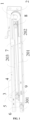
FIG. 1 is an axis side view of a linear motion mechanism provided by an embodiment of the present application, where a first-stage sliding rail and a second-stage sliding rail are in a retraction position. -
FIG. 2 is a front view of a linear motion mechanism provided by an embodiment of the present application, where a first-stage sliding rail and a second-stage sliding rail are in a retraction position. -
FIG. 3 is a top view of a linear motion mechanism provided by an embodiment of the present application, where a first-stage sliding rail and a second-stage sliding rail are in a retraction position. -
FIG. 4 is a right view of a linear motion mechanism provided by an embodiment of the present application -
FIG. 5 is an axis side view of a linear motion mechanism provided by an embodiment of the present application, where a first-stage sliding rail is in an extension position. -
FIG. 6 is a front view of a linear motion mechanism provided by an embodiment of the present application, where a first-stage sliding rail is in an extension position. -
FIG. 7 is a top view of a linear motion mechanism provided by an embodiment of the present application, where a first-stage sliding rail is in an extension position. -
FIG. 8 is a side view of a linear motion mechanism provided by an embodiment of the present application, where the linear motion mechanism includes a second fixed pulley. - 1: rotating wheel; 2: flexible cable; 201: first flexible cable segment; 202: second flexible cable segment; 203: third flexible cable segment; 3: installation member; 301: guiding rail; 4: first-stage sliding rail; 5: second-stage sliding rail; 6: first fixed pulley; 7: sliding block; 8: first movable pulley; 9: second movable pulley; 10: second fixed pulley.
- The implementation of the present application is further described in detail below in combination with the accompanying drawings and embodiments. The following embodiments are used to describe the present application, but cannot be used to limit the scope of the present application.
- In the description of the present application, it is to be noted that, the orientation or positional relations specified by terms such as "central", "longitudinal", "transverse", "upper", "lower", "front", "back", "left", "right", "vertical", "horizontal", "top", "bottom", "inner", "outer" and the like, are based on the orientation or positional relations shown in the drawings, which is merely for convenience of description of the present application and to simplify description, but does not indicate or imply that the stated devices or members must have the particular orientation and be constructed and operated in a particular orientation, and thus it is not to be construed as limiting the present application. Furthermore, the terms "first", "second", "third" and the like are only used for descriptive purposes and should not be construed as indicating or implying a relative importance.
- In the description of the present application, it is to be noted that unless explicitly specified and defined otherwise, the terms "connected to" and "connected" shall be understood broadly, for example, it may be either fixedly connected or detachably connected, or can be integrated; it may be either mechanically connected, or electrically connected; it may be either directly connected, or indirectly connected through an intermediate medium. The specific meanings of the terms above in the present application can be understood by a person skilled in the art in accordance with specific conditions.
- In the embodiments of the present application, unless otherwise expressly specified and defined, a first feature is "on" or "under" a second feature can refer to that the first feature is directly contacted with the second feature, or the first feature is indirectly contacted with the second feature through an intermediate medium. And further, the first feature is "on", "above" and "over" the second feature can refer to that the first feature is directly above or obliquely above the second feature, or simply refer to that the stage height of the first feature is higher than that of the second feature. The first feature is "under", "below" and "beneath" the second feature can refer to that the first feature is directly below or obliquely below the second feature, or simply refer to that the stage height of the first feature is lower than that of the second feature.
- In the description of this specification, description with reference to the terms "one embodiment", "some embodiments", "an example", "specific example", "some examples" and the like, refers to that specific features, structures, materials or characteristics described in combination with an embodiment or an example are included in at least one embodiment or example according to the embodiments of the present application. In this specification, schematic representations of the above terms are not necessarily directed to a same embodiment or example. Furthermore, the particular features, structures, materials or characteristics described can be combined in any suitable manner in any one or more embodiments or examples. In addition, those skilled in the art may combine the different embodiments or examples described in this specification, as well as the features of the different embodiments or examples, without conflicting each other.
- As shown in
FIG. 1 to FIG. 7 , the linear motion mechanism according to an embodiment of the present application includes arotating wheel 1, a rotating driving member (not shown in the figures), aninstallation member 3 and a first-stage sliding rail 4. Therotating wheel 1 is wrapped by aflexible cable 2, whereflexible cable 2 is configured to move as therotating wheel 1 rotating, and theflexible cable 2 includes cable segments on two sides of therotating wheel 1. The rotating driving member is connected with therotating wheel 1, and is configured to drive therotating wheel 1 to rotate. Theinstallation member 3 is provided with a guidingrail 301, and theinstallation member 3 is provided with a first fixedpulley 6. The first-stage sliding rail 4 is configured to slide relative to the guidingrail 301. Theflexible cable 2 wraps the first fixedpulley 6, and the flexible cable segment of theflexible cable 2 located on two sides of therotating wheel 1 is connected to the first-stage sliding rail 4. - According to the linear motion mechanism provided by the embodiments of the present application, the linear motion mechanism only needs to be added with a
rotating wheel 1, a rotating driving member and a pulley to operate automatically (where the pulley includes a fixed pulley, and can further include a movable pulley, and the fixed pulley refers to at least one of a first fixedpulley 6, a second fixedpulley 10, and a third fixed pulley in the absence of specific limitations), and thus occupies a small space and has a simple structure without greatly increasing the preparation cost of the linear motion mechanism. In addition, since the assembly and disassembly of therotating wheel 1 only involves the rotating driving member and the pulley, the assembly and disassembly are more convenient. - According to the linear motion mechanism of the present application embodiment, the rotating driving member can lead the
rotating wheel 1 to rotate, and then therotating wheel 1 leads theflexible cable 2 to move. On this basis, since theflexible cable 2 wraps the first fixedpulley 6, and the flexible cable segment on two sides of therotating wheel 1 is connected to the first-stage sliding rail 4, theflexible cable 2 can lead the first-stage sliding rail 4 to move linearly relative to the guidingrail 301. As rotation directions of therotating wheel 1 vary, the first-stage sliding rail 4 performs linear motion in different directions relative to the guidingrail 301. InFIG. 1 , when therotating wheel 1 rotates clockwise, theflexible cable 2 leads the first-stage sliding rail 4 to move towards a right side ofFIG. 1 relative to the guidingrail 301. When therotating wheel 1 rotates counterclockwise, theflexible cable 2 leads the first-stage sliding rail 4 to move towards a left side ofFIG. 1 relative to the guidingrail 301. - It should be noted that the function of the linear motion mechanism is to make a certain point on the mechanism move accurately or approximately linearly. That is, the motion of the linear motion mechanism here includes approximate linear motion. In addition, for the pulley group including the
flexible cable 2 and the first fixedpulley 6, the motion of theflexible cable 2 will only lead the first fixedpulley 6 to rotate without the changing spatial position of the first fixedpulley 6. - According to the embodiments of the present application, the structural form of guiding
rail 301 is not limited. When the first-stage sliding rail 4 is directly provided on the guidingrail 301, the guidingrail 301 only needs to play a guiding role on the first-stage sliding rail 4. For example, the guidingrail 301 can include a guiding groove, and then the first-stage sliding rail 4 can move along an extension direction of the guiding groove; or, the guidingrail 301 can include a guiding protrusion, and then the first-stage sliding rail 4 can move along the extension direction of the guiding protrusion. In addition, the guidingrail 301 can be integrally formed on theinstallation member 3 or can be an individual member fixed to theinstallation member 3. - Similarly, the structural form of the first-
stage sliding rail 4 is not limited, as long as it can form a guiding matching with the guidingrail 301, the first-stage sliding rail 4 can move linearly or approximately linearly relative to the guidingrail 301. For example, the first-stage sliding rail 4 and the guidingrail 301 can be matching by a matching protrusion and groove, or a sliding member such as a pulley can be provided between the sliding rail and the guidingrail 301, and then the first-stage sliding rail 4 and the guidingrail 301 are matched by the sliding member. - The first-
stage sliding rail 4 can be an individual member, and can also be formed in a drawer, a shelf board, or the like. The drawer or shelf board configured to be installed on the guidingrail 301 can be taken as a slidingrail 4. A second-stage sliding rail 5 and a third-stage sliding rail can further be installed between the first-stage sliding rail 4 and the guidingrail 301. The first-stage sliding rail 4 is installed on the sliding rail through the second-stage sliding rail 5 and the third-stage sliding rail instead of being directly installed on the guidingrail 301. - An intermediate sliding rail can be provided between the first sliding
rail 4 and the guidingrail 301, and the intermediate sliding rail is provided with a movable pulley, the flexible cable wraps the first fixedpulley 6 and the movable pulley (in the absence of special limitations, the movable pulley refers to a firstmovable pulley 8 and a secondmovable pulley 9 provided on the second-stage sliding rail 5, or it further includes movable pulleys provided on other intermediate sliding rails when more intermediate sliding rails are included), so that the first-stage sliding rail 4 moves relative to the intermediate sliding rail, and the intermediate sliding rail moves relative to the guidingrail 301. The number of intermediate sliding rails is not limited. When there is one intermediate sliding rail, the intermediate sliding rail is a second-stage sliding rail 5; when there is two intermediate sliding rails, the intermediate sliding rails includes a second-stage sliding rail 5 and a third-stage sliding rail; and when there is three intermediate sliding rails, the intermediate sliding rail includes a second-stage sliding rail 5, a third-stage sliding rail and a fourth-stage sliding rail; and so on. When intermediate sliding rails are provided, the first-stage sliding rail 4 is installed on the sliding rail through the intermediate sliding rails such as the second-stage sliding rail 5 and the third-stage sliding rail instead of being directly installed on the guidingrail 301. - According to the embodiments of the present application, the intermediate sliding rail including the second-
stage sliding rail 5 is taken as an example. The second-stage sliding rail 5 is installed on the guidingrail 301 and is configured to slide along the guidingrail 301, and the second-stage sliding rail 5 is provided with the firstmovable pulley 8 and the secondmovable pulley 9. The first-stage sliding rail 4 is provided on the second-stage sliding rail 5 and is configured to move relative to the second-stage sliding rail 5. Theflexible cable 2 wraps the first fixedpulley 6, the firstmovable pulley 8 and the secondmovable pulley 9 in sequence. By providing the second-stage sliding rail 5, the linear motion mechanism can perform multistage telescopic motions, which ensures the telescopic route of the linear motion mechanism. - According to the embodiments of the present application, when the linear motion mechanism includes both the first-
stage sliding rail 4 and the second-stage sliding rail 5, the linear motion mechanism can perform second-stage telescopic motion, which corresponds to a third-stage linear motion. The linear motion mechanism can further include a third-stage sliding rail, a fourth-stage sliding rail, a fifth-stage sliding rail or the like (the sliding rail refers to at least one of the first-stage sliding rail 4, second-stage sliding rail 5, third-stage sliding rail and the like.), the specific number of the sliding rails is not limited and can be determined according to requirements. The first-stage sliding rail 4 refers to the first sliding rail led by the rotation of the rotating driving member to perform telescopic motion. The second-stage sliding rail 5 refers to the second sliding rail led by the continuous motion of the rotating driving member to perform telescopic motion when the first slidingrail 4 moves to a limiting position. the three-stage slide refers to the third sliding rail led by the continuous motion of the rotating driving member to perform telescopic motion when the two-stage sliding rail 5 moves to the limiting position; and so on. - According to the embodiments of the present application, the linear motion mechanism further includes a sliding
block 7, which is fixed on the first-stage sliding rail 4 and configured to linear motion along the second-stage sliding rail 5, and the slidingblock 7 is fixedly connected to the flexible cable segment on two sides of therotating wheel 1. The fixing form between the slidingblock 7 and the flexible cable segment is not limited. For example, the slidingblock 7 and the flexible cable segment can be bound, or the slidingblock 7 and the flexible cable segment can be welded. - The providing of the sliding
block 7 can facilitate the assembly between the first-stage sliding rail 4 and the second-stage sliding rail 5, and can facilitate the providing offlexible cable 2. The flexible cable segment on two sides of therotating wheel 1 can also be directly connected to the first-stage sliding rail 4 without providing the slidingblock 7. - According to the embodiments of the present application, the sliding
block 7 is fixed at a back end of the first-stage sliding rail 4 along the extension direction of the first-stage sliding rail 4 relative to the second-stage sliding rail 5, referring toFIG. 1 to FIG. 3 , that is, the slidingblock 7 is provided at the back end of the first-stage sliding rail 4. In this case, the route of the first-stage sliding rail 4 relative to the second-stage sliding rail 5 can be ensured. The slidingblock 7 can also be provided at other positions of the first-stage sliding rail 4 when the route of the first-stage sliding rail 4 meets the requirements. - According to the embodiments of the present application, the first
movable pulley 8 and the secondmovable pulley 9 are located at two ends of the second-stage sliding rail 5 respectively, and the route of the second-stage sliding rail 5 relative to the guidingrail 301 is ensured. In combination withFIG. 1 to FIG. 3 , the firstmovable pulley 8 is provided at a right end of the second-stage sliding rail 5, and the secondmovable pulley 9 is provided at a left end of the second-stage sliding rail 5. - In an embodiment, the first
movable pulley 8 and the secondmovable pulley 9 can be provided at other positions of the second-stage sliding rail 5 when the route of the second-stage sliding rail 5 meets the requirements. - According to the embodiments of the present application, the
flexible cable 2 includes a firstflexible cable segment 201, a secondflexible cable segment 202 and a thirdflexible cable segment 203. The firstflexible cable segment 201 is located between the first fixedpulley 6 and the firstmovable pulley 8; the secondflexible cable segment 202 is located between the firstmovable pulley 8 and the secondmovable pulley 9; and the thirdflexible cable segment 203 is located between the secondmovable pulley 9 and the first slidingrail 4. - In
FIG. 1 , certain angles are provided between the firstflexible cable segment 201, the secondflexible cable segment 202 and the thirdflexible cable segment 203. In order to ensure the smooth operation of theflexible cable 2 and save the power of the rotating driving member under the same conditions, the firstflexible cable segment 201, the secondflexible cable segment 202 and the thirdflexible cable segment 203 can be provided in parallel with each other. - According to the embodiments of the present application, the
rotating wheel 1 is provided on theinstallation member 3. In this case, all members of the linear motion mechanism can be ensured to be as concentrated as possible, and the convenience during assembly and disassembly is ensured. - The
rotating wheel 1 can also be provided at other positions, as long as the rotating driving member can lead theflexible cable 2 to move through therotating wheel 1. In addition, the position of the rotating driving member being provided is not limited, as long as therotating wheel 1 can be driven to rotate. In particular, when the above linear motion mechanism is applied to a refrigerator, the rotating driving member has no spatial constraint, which can facilitate the providing of the linear motion mechanism in the refrigerator. - According to the embodiments of the present application, taking the rotating driving member being a motor as an example, the motor does not need to move following the sliding rail of the linear motion mechanism, which avoids the dynamic bending of a wire of the motor.
- According to the embodiments of the present application, when the linear motion mechanism further includes the second-
stage sliding rail 5 and the firstmovable pulley 8 and the secondmovable pulley 9 provided on the second-stage sliding rail 5, therotating wheel 1 is provided corresponding to the first fixedpulley 6, the firstmovable pulley 8 and the secondmovable pulley 9, and a diameter of therotating wheel 1 is larger than that of the first fixedpulley 6, the firstmovable pulley 8 and the secondmovable pulley 9. The phrase "therotating wheel 1 is provided corresponding to the first fixedpulley 6, the firstmovable pulley 8 and the secondmovable pulley 9" refers to therotating wheel 1 which is provided on a straight line where the firstmovable pulley 8 and the secondmovable pulley 9 are located, or the straight line where the firstmovable pulley 8 and the secondmovable pulley 9 are located has small distance to therotating wheel 1, and then the smooth motion of theflexible cable 2 is ensured. In addition, the diameter of therotating wheel 1 is larger than that of the firstmovable pulley 8 and the secondmovable pulley 9, and then the flexible cable segments on the two sides of therotating wheel 1 being tangent to therotating wheel 1 is ensured, to further ensure the smooth operation of theflexible cable 2. - In
FIG. 3 to FIG. 7 , the flexible cable segments on two sides of therotating wheel 1 include the flexible cable segment extending from an upper side of therotating wheel 1 and the flexible cable segment extending from a lower side of the rotating wheel. The flexible cable segment extending from the lower side of therotating wheel 1 includes a flexible cable segment between therotating wheel 1 and the first fixedpulley 6, as well as the firstflexible cable segment 201, the secondflexible cable segment 202 and the thirdflexible cable segment 203 mentioned above. In addition, the flexible cable segment extending from the upper side of therotating wheel 1 includes a flexible cable segment between therotating wheel 1 and the first-stage sliding rail 4. - When the
rotating wheel 1 rotates counterclockwise, the flexible cable segment between therotating wheel 1 and the first fixedpulley 6 moves to the right and leads the first fixedpulley 6 to move counterclockwise; the firstflexible cable segment 201 moves to the left and leads the firstmovable pulley 8 to rotate clockwise, the secondflexible cable segment 202 moves to the right and leads the secondmovable pulley 9 to move counterclockwise, the thirdflexible cable segment 203 moves to the left and leads the first slidingrail 4 to move to the left through the slidingblock 7. When the first-stage sliding rail 4 moves to the left to the limiting position, if therotating wheel 1 continues to rotate counterclockwise, since the firstflexible cable segment 201 moves to the left, the firstmovable pulley 8 is driven to move to the left, and then the second-stage sliding rail 5 moves to the left. When the first-stage sliding rail 4 moves to the left, a flexible cable segment between therotating wheel 1 and the slidingblock 7 becomes longer, and the flexible cable segment between the second movingwheel 9 and the slidingblock 7 becomes shorter. When the second-stage sliding rail 5 moves to the left, a flexible cable segment between the first fixedpulley 6 and the firstmovable pulley 8 becomes shorter, and the flexible cable segment between therotating wheel 1 and the slidingblock 7 continues to become longer. - When the
rotating wheel 1 rotates clockwise, the flexible cable segment between therotating wheel 1 and the first-stage sliding rail 4 moves to the right, and then the first-stage sliding rail 4 is driven to move to the right. When the first-stage sliding rail 4 moves to the right to the limiting position, if therotating wheel 1 continues to rotate clockwise, since the flexible cable segment between therotating wheel 1 and the first-stage sliding rail 4 continues to move to right, and then a thirdflexible cable segment 203 between the first-stage sliding rail 4 and the second-stage slide 9 will also move right, and lead the second-stage slide 9 to move right to drive the second-stage sliding rail 5 to move to the right. When the first-stage sliding rail 4 moves to the right, the flexible cable segment between therotating wheel 1 and the slidingblock 7 becomes shorter, and the flexible cable segment between the secondmovable pulley 9 and the slidingblock 7 becomes longer. When the second-stage sliding rail 5 moves to the right, the flexible cable segment between the first fixedpulley 6 and the firstmovable pulley 8 becomes longer, and the flexible cable segment between therotating wheel 1 and the slidingblock 7 continues to become shorter. - According to the embodiments of the present application, referring to
FIG. 8 , the linear motion mechanism further includes a second fixedpulley 10, and the second fixedpulley 10 is provided to theinstallation member 3. In this case, theflexible cable 2 wraps thesecond pulley 10 and the first fixedpulley 6 in sequence. When the linear motion mechanism includes the firstmovable pulley 8 and the secondmovable pulley 9, theflexible cable 2 wraps the second fixedpulley 10, the first fixedpulley 6, the firstmovable pulley 8 and the secondmovable pulley 9 in sequence. The providing of the second fixedpulley 10 can make the providing of therotating wheel 1 more flexible. For example, therotating wheel 1 can be provided outside theinstallation member 3. When the linear motion mechanism is installed in a drawer body, the installation position of therotating wheel 1 and the rotating driving member relative to the drawer body is selected according to the situation. - In an embodiment, the first fixed
pulley 6 is located at a first end of the guidingrail 301, and the second fixedpulley 10 is located at a second end of the guidingrail 301. Alternatively, the second fixedpulley 10 is located on an extension path of the guidingrail 301 and is close to the second end of the guidingrail 301. By providing the position relationship between the first fixedpulley 6 and the second fixedpulley 10 reasonably, the smooth operation of the flexible cable is ensured. The providing position of the second fixedpulley 10 is not limited, as long as theflexible cable 2 can move smoothly along the directions of therotating wheel 1, the second fixedpulley 10, the first fixedpulley 6, the firstmovable pulley 8 and the secondmovable pulley 9. - According to the embodiments of the present application, the
rotating wheel 1 can be a synchronous belt wheel or a pulley, and theflexible cable 2 can be a belt or a flexible belt with high friction coefficient. For example, therotating wheel 1 can select the belt wheel and theflexible cable 2 can select the belt matching the belt wheel. This situation can ensure that when therotating wheel 1 rotates, theflexible cable 2 is led to move, and avoids theflexible cable 2 slipping relative to therotating wheel 1. Similarly, the specific structure of theflexible cable 2 is not limited, for example, it can be a wire rope. - The specific structural form of the
rotating wheel 1 andflexible cable 2 is not limited, as long as the rotation of therotating wheel 1 can lead theflexible cable 2 to move, and prevent theflexible cable 2 from slipping as far as possible. - According to the embodiments of the present application, the rotating driving member can be, but is not limited to, a motor including a linear motor and a rotary motor, as long as the rotating driving member can be used as a power source to drive the
rotating wheel 1 to rotate. For example, the rotating driving member can also be a pneumatic cylinder, which can convert the linear motion into rotation of therotating wheel 1 through a gear rack pair. - According to the embodiments of the present application, several tensioning wheels can be provided in the extension direction of
flexible cable 2 to ensure thatflexible cable 2 is in a tensioning state. For example, when a second fixedpulley 10 is provided, and therotating wheel 1 and the rotating driving member are provided outside the installation member, in order to avoid the loosening of the flexible cable between therotating wheel 1 and the second fixedpulley 10, a tension wheel can be provided between the second fixedpulley 10 and therotating wheel 1. The tensioning wheel can adjust a direction of the flexible cable between therotating wheel 1 and the second fixedpulley 10. - According to the embodiments of the present application, a drawer assembly is provided, which includes a drawer body, and further includes the linear motion mechanism mentioned above. The drawer body is fixed on the first-
stage sliding rail 4. - According to the embodiments of the present application, the
rotating wheel 1 is driven to rotate by the rotating driving member, and theflexible cable 2 is led to move, to make the first-stage sliding rail 4 slide relative to the guiding rail. Further, when the drawer body is installed on the first slidingrail 4, the drawer body can move relative to theinstallation member 3, so that the drawer can be pulled automatically. - It should be noted that the drawer assembly that can be pulled automatically in the present application can be modified on the basis of the drawer assembly in related art. In an embodiment, it only needs to add with the
rotating wheel 1, rotating driving member and fixed pulley, or further add the movable pulley, thereby having lower preparation cost. - According to the embodiments of the present application, the automatic pulling of the drawer body can be controlled by providing with a corresponding switch or sensor. For example, a switch is provided in a panel portion of the drawer body, and then the drawer is automatically extended by pressing the switch, and the drawer is automatically retracted by pressing the switch again. For example, a sensor is provided in the panel portion of the drawer body. When the sensor senses a corresponding action, such as when a hand is approaching, a signal is generated to control the drawer body to extend or retract.
- According to the embodiments of the present application, a storage cabinet is provided, which includes a box body and a drawer body and/or a shelf provided in the box body, and further includes the linear motion mechanism mentioned above, where the linear motion mechanism is provided on at least one side of the drawer body and/or shelf, the drawer body and/or shelf are fixed on the first-
stage sliding rail 4, and theinstallation member 3 is fixed on the box body. - That is, the box body is provided with at least one of the drawer body and shelf. On this basis, both the drawer body and the shelf can be provided in the box body through the above linear motion mechanism.
- The drawer body and/or shelf of a storage cabinet according to the present application embodiment can be pulled automatically to facilitate the taking and placing of object. In addition, the linear motion mechanism between the drawer body and/or the shelf and the box body have small space occupation and a simple structure, thereby hardly occupying additional space inside the box body. In addition, the linear motion mechanism has low preparation cost and is convenient to be assembled and disassembled, which has high applicability, and can be applied to various products such as refrigerators, wardrobes, and display cabinets.
- The
installation member 3 can be a detachable individual member provided in the box body, and theinstallation member 3 can also be integrated into the box body. - According to the storage cabinet of the present application embodiment, the first sliding
rail 4 and theinstallation member 3 are provided along a height direction of the storage cabinet in sequence. Therefore, the weight of the drawer body or the shelf is transmitted to theinstallation member 3 through the first-stage sliding rail 4, and theinstallation member 3 needs to have sufficient structural strength. The first-stage sliding rail 4 can be fixed to the side wall of the drawer body or the shelf. In this case, the lateral space occupied by the linear motion mechanism is small. - According to the storage cabinet of another embodiment of the present application, the first-
stage sliding rail 4 and theinstallation member 3 are provided along a width direction of the storage cabinet in sequence, and the first-stage sliding rail 4 is fixed with the bottom plate of the drawer or the bottom plate of the shelf. In this case, the main function of theinstallation member 3 is to guide the moving direction of the first-stage sliding rail 4 by providing the guidingrail 301. The drawer body or shelf can be supported by an additional load-bearing member. Further, in order to ensure that the drawer body or shelf to move relative to theinstallation member 3, a roller can be provided in the drawer body or at a bottom of the shelf, and the rolling friction between the roller and load-bearing member can ensure that the drawer body or shelf move smoothly. In this case, there is no great requirement for the structural strength of theinstallation member 3, as long as the guidingrail 301 can play a guiding role on the first slidingrail 4. - According to the storage cabinet of the present application embodiment, the
rotating wheel 1 is installed on an inner side of the storage cabinet. When therotating wheel 1 moves, a certain noise will be generated. By installing therotating wheel 1 on the inner side of the storage cabinet, the noise generated from the storage cabinet can be reduced. The phrase "the inner side of the storage cabinet" refers to a side distal to the door, and a side near the door refers to an outside of the storage cabinet. During use, the "the inner side of the storage cabinet" is a side distal to the user. - According to the storage cabinet of the present application, the storage cabinet can be a refrigerator, a retail cabinet or a display cabinet, and the specific structural form of the storage cabinet is not limited by the embodiment here. The linear motion mechanism of the embodiments of the present application is not limited to the storage cabinet of the present application, but can be used in other occasions, for example, a drawer of a desk, a flat door and a telescopic manipulator can switch states through the above linear motion mechanism.
- The following takes the extension and retraction of the drawer in the refrigerator as an example to explain the linear motion mechanism of the present application.
- The
installation member 3 of the linear motion mechanism inFIG. 1 to FIG. 7 is installed on a tank of the refrigerator, and the first-stage sliding rail 4 of the linear motion mechanism is provided on the drawer body. - When food needs to be taken or placed on an outer side of the drawer body, the first-
stage sliding rail 4 of the linear motion mechanism is triggered to extend relative to the second-stage sliding rail 5. If food needs to be taken or placed on an inner side of the drawer body, the second-stage sliding rail 5 of the linear motion mechanism is triggered to extend relative to the guiding rail. In an embodiment, the rotating driving member leads therotating wheel 1 to move counterclockwise so that the first-stage sliding rail 4 and even the second-stage sliding rail 5 to extend out. The sensor can be provided at a corresponding position of the refrigerator. When a corresponding operation is continuously sensed, the rotating driving member continues to operate, so that the drawer body gradually extends out. When the corresponding operation disappears, the rotating driving member no longer operates, and the drawer body stops at the current position. For example, a pressing sensor is provided in the drawer body, the door body or the tank. Since being subjected to a pressing operation, the rotating driving member continuously drives therotating wheel 1 to rotate to lead the drawer body to extend out. For another example, the pressure sensor can also be replaced by an infrared sensor or other type of sensor. When the drawer body needs to be retracted, there is no need for continuous sensing, and only one operation is needed to retract the drawer body. The linear motion mechanism can also be controlled based on sound signals. For example, based on sound information such as "open the drawer" or "close the drawer", the drawer body can switch states. - The above embodiments are only used to illustrate the present application, rather than limiting the present application. Although the present application is described in detail with reference to the above embodiments, those of ordinary skill in the art should understand that the various combinations, modifications or equivalent replacements of the solutions of the present application are not departed from the scope of the solutions of the present application, and should be covered in the scope of the claims of the present application.
Claims (17)
- A linear motion mechanism, comprising:a rotating wheel (1), wrapped by a flexible cable (2), wherein the flexible cable (2) is configured to move as the rotating wheel (1) rotates, and the flexible cable (2) comprises a flexible cable segment located on two sides of the rotating wheel (1);a rotating driving member, connected with the rotating wheel (1), and configured to drive the rotating wheel (1) to rotate;an installation member (3), provided with a guiding rail (301), wherein a first fixed pulley (6) is installed on the installation member (3); anda first-stage sliding rail (4), configured to slide relative to the guiding rail (301);wherein the flexible cable (2) wraps the first fixed pulley (6), and the flexible cable segment of the flexible cable (2) located on the two sides of the rotating wheel (1) are connected to the first-stage sliding rail (4).
- The linear motion mechanism according to claim 1, wherein a number of intermediate sliding rails are provided between the first-stage sliding rail (4) and the guiding rail (301), and the first-stage sliding rail (4) is installed on the guiding rail (301) through the intermediate sliding rails, the intermediate sliding rail is provided with a movable pulley, and the flexible cable warps the first fixed pulley and the movable pulley in sequence.
- The linear motion mechanism according to claim 2, further comprising:a second-stage sliding rail (5), installed on the guiding rail (5), configured to slide along the guiding rail (301), and provided with a first movable pulley (8) and a second movable pulley (9);wherein the first-stage sliding rail (4) is installed on the second-stage sliding rail (5) and is configured to move relative to the second-stage sliding rail (5); andthe flexible cable (2) warps the first fixed pulley (6), the first movable pulley (8) and the second movable pulley (9) in sequence.
- The linear motion mechanism according to claim 3, further comprising:
a sliding block (7), fixed on the first-stage sliding rail (4) and configured to perform linear motion along the second-stage sliding rail (5), and fixedly connected to the flexible cable segment on the two sides of the rotating wheel (1). - The linear motion mechanism according to claim 4, wherein the sliding block (7) is fixed at a back end of the first-stage sliding rail (4) along an extension direction of the first-stage sliding rail (4) relative to the second-stage sliding rail (5).
- The linear motion mechanism according to claim 3, wherein the first movable pulley (8) and the second movable pulley (9) are respectively provided at two ends of the second-stage sliding rail (5).
- The linear motion mechanism according to claim 3, wherein the flexible cable (2) comprises:a first flexible cable segment, located between the first fixed pulley (6) and the first movable pulley (8);a second flexible cable segment, located between the first movable pulley (8) and the second movable pulley (9); anda third flexible cable segment, located between the second movable pulley (9) and the first-stage sliding rail (4);wherein the first flexible cable segment, the second flexible cable segment and the third flexible cable segment are parallel, or angles are provided between the first flexible cable segment and the second flexible cable segment, and between the second flexible cable segment and the third flexible cable segment.
- The linear motion mechanism according to any one of claims 1 to 7, wherein the rotating wheel (1) is provided on the installation member (3).
- The linear motion mechanism according to claim 8, wherein when the linear motion mechanism further comprises a second-stage sliding rail (5) and a first movable pulley (8) and a second movable pulley (9) provided on the second-stage sliding rail (5), the rotating wheel (1) is provided correspondingly to the first fixed pulley (6), the first movable pulley (8) and the second movable pulley (9), and a diameter of the rotating wheel (1) is larger than diameters of the first fixed pulley (6), the first movable pulley (8) and the second movable pulley (9).
- The linear motion mechanism according to any one of claims 1-7, further comprising:a second fixed pulley, provided on the installation member (3), wherein the flexible cable (2) wraps the second fixed pulley and the first fixed pulley (6) in sequence;wherein the first fixed pulley (6) is located at a first end of the guiding rail (301), and the second fixed pulley is located at a second end of the guiding rail (301), or the second fixed pulley is located on an extended path of the guiding rail (301) and close to the second end of the guiding rail (301).
- The linear motion mechanism according to any one of claims 1-7, wherein the rotating wheel (1) is a belt wheel, and the flexible cable (2) is a belt matching with the belt wheel.
- A drawer assembly, comprising a drawer body and the linear motion mechanism according to any one claims 1 to 11, wherein the drawer body is fixed on the first-stage pulley (4).
- A storage cabinet, comprising a box body and a drawer body and/or a shelf provided in the box body, and the linear motion mechanism according to any one of claims 1 to 11, wherein the linear motion mechanism is provided on at least one side of the drawer body and/or the shelf, the drawer body and/or the shelf are fixed on the first-stage sliding rail (4), and the installation member (3) is fixed on the box body.
- The storage cabinet according to claim 13, wherein the first-stage sliding rail (4) and the installation member (3) are provided along a height direction of the storage cabinet in sequence, and the first-stage sliding rail (4) is fixed with a side wall of the drawer body or a side wall of the shelf.
- The storage cabinet according to claim 13, wherein the first-stage sliding rail (4) and the installation member (3) are provided along a width direction of the storage cabinet in sequence, and the first-stage sliding rail (4) is fixed with a bottom plate of the drawer body or a bottom plate of the shelf.
- The storage cabinet according to any one of claims 13-15, wherein the rotating wheel (1) is installed on an inner side of the storage cabinet.
- The storage cabinet according to any one of claims 13-15, wherein the storage cabinet is a refrigerator, a retail cabinet or a display cabinet.
Applications Claiming Priority (2)
| Application Number | Priority Date | Filing Date | Title |
|---|---|---|---|
| CN202110282980.9A CN112956846B (en) | 2021-03-16 | 2021-03-16 | Linear motion mechanism, drawer assembly and locker |
| PCT/CN2021/142520 WO2022193778A1 (en) | 2021-03-16 | 2021-12-29 | Linear motion mechanism, drawer assembly, and storage cabinet |
Publications (3)
| Publication Number | Publication Date |
|---|---|
| EP4137006A1 true EP4137006A1 (en) | 2023-02-22 |
| EP4137006A4 EP4137006A4 (en) | 2023-11-22 |
| EP4137006B1 EP4137006B1 (en) | 2025-02-12 |
Family
ID=76277805
Family Applications (1)
| Application Number | Title | Priority Date | Filing Date |
|---|---|---|---|
| EP21931350.9A Active EP4137006B1 (en) | 2021-03-16 | 2021-12-29 | Linear motion mechanism, drawer assembly, and storage cabinet |
Country Status (4)
| Country | Link |
|---|---|
| US (1) | US12150549B2 (en) |
| EP (1) | EP4137006B1 (en) |
| CN (1) | CN112956846B (en) |
| WO (1) | WO2022193778A1 (en) |
Families Citing this family (10)
| Publication number | Priority date | Publication date | Assignee | Title |
|---|---|---|---|---|
| EP3919770B1 (en) * | 2020-06-05 | 2022-09-14 | Accuride International GmbH | Telescopic rail |
| CN112956846B (en) * | 2021-03-16 | 2024-08-06 | 合肥美的电冰箱有限公司 | Linear motion mechanism, drawer assembly and locker |
| CN115682610A (en) * | 2021-07-30 | 2023-02-03 | 重庆海尔制冷电器有限公司 | Electric slide rail |
| CN115868749A (en) * | 2021-09-30 | 2023-03-31 | 合肥美的电冰箱有限公司 | Storing cabinet |
| EP4180754B1 (en) | 2021-09-30 | 2025-07-02 | Hefei Midea Refrigerator Co., Ltd. | Shelf and storage cabinet |
| CN113965042A (en) * | 2021-10-08 | 2022-01-21 | 南昌云华起智能科技有限公司 | Sliding rail device adopting hidden linear motor and control strategy thereof |
| EP4274044A1 (en) * | 2022-05-02 | 2023-11-08 | Accuride International GmbH | Linear guide system |
| CN117662684A (en) * | 2022-08-23 | 2024-03-08 | 合肥美的电冰箱有限公司 | Flexible rope winding method, connectors, linear transmission mechanism, linear motion device |
| CN117662700A (en) * | 2022-08-23 | 2024-03-08 | 合肥美的电冰箱有限公司 | Linear drives, drawer assemblies and storage cabinets |
| CN117652797A (en) * | 2022-08-23 | 2024-03-08 | 合肥美的电冰箱有限公司 | Drawer assemblies and storage cabinets |
Family Cites Families (17)
| Publication number | Priority date | Publication date | Assignee | Title |
|---|---|---|---|---|
| DE19921872A1 (en) * | 1999-05-11 | 2000-11-23 | Rexroth Star Gmbh | Guide device comprising rail and component which moves along it on rollers has lubricating device which picks up lubricant from feed chamber and can be moved between rail and moving component to lubricate each in turn |
| DE10228470A1 (en) * | 2002-06-26 | 2004-01-15 | Grass Gmbh | drawer guide |
| AT504375B1 (en) * | 2006-10-23 | 2010-01-15 | Blum Gmbh Julius | FURNITURE WITH A DRIVE DEVICE FOR MOVABLE FURNITURE PARTS |
| AT505562B1 (en) * | 2007-07-24 | 2013-04-15 | Blum Gmbh Julius | FURNITURE DRIVE |
| AT506441A1 (en) | 2008-03-07 | 2009-09-15 | Blum Gmbh Julius | MICRICULAR DRIVE WITH A DRIVE UNIT |
| CN203928564U (en) * | 2014-05-28 | 2014-11-05 | 青岛海尔股份有限公司 | Drawer type door body assembly and refrigerator thereof |
| DE102014119729B4 (en) * | 2014-12-30 | 2024-04-11 | Paul Hettich Gmbh & Co. Kg | Linear guide for moving parts of furniture, household appliances or the like |
| WO2019074271A1 (en) * | 2017-10-12 | 2019-04-18 | (주)세고스 | Sliding device |
| CN107989501A (en) * | 2017-12-26 | 2018-05-04 | 无锡晶美精密滑轨有限公司 | Slide synchronous-belt regulating device |
| CN108916226B (en) * | 2018-08-24 | 2023-08-18 | 无锡海达尔精密滑轨股份有限公司 | Three-section synchronous slide rail |
| WO2020242393A1 (en) * | 2019-05-27 | 2020-12-03 | Samet Kalip Ve Madeni̇ Eşya San Ti̇c. A.Ş | Ball rail system for drawers |
| CN210329882U (en) * | 2019-07-04 | 2020-04-17 | 无锡太湖学院 | Teaching plan case for accounting management |
| CN112240666B (en) * | 2019-07-16 | 2024-09-24 | 海信冰箱有限公司 | Refrigerator with lifting shelves |
| CN212066094U (en) * | 2019-12-27 | 2020-12-04 | 刘艳华 | Aluminum alloy multi-section sliding rail with bearing roller |
| CN111568080B (en) * | 2020-05-22 | 2024-08-23 | 中国人民解放军空军特色医学中心 | Two-pin four-hole drawer fixing mechanism used on airplane |
| CN212585282U (en) * | 2020-06-15 | 2021-02-23 | 海信容声(扬州)冰箱有限公司 | A kind of refrigerator |
| CN112956846B (en) * | 2021-03-16 | 2024-08-06 | 合肥美的电冰箱有限公司 | Linear motion mechanism, drawer assembly and locker |
-
2021
- 2021-03-16 CN CN202110282980.9A patent/CN112956846B/en active Active
- 2021-12-29 WO PCT/CN2021/142520 patent/WO2022193778A1/en not_active Ceased
- 2021-12-29 EP EP21931350.9A patent/EP4137006B1/en active Active
- 2021-12-29 US US17/925,013 patent/US12150549B2/en active Active
Also Published As
| Publication number | Publication date |
|---|---|
| CN112956846B (en) | 2024-08-06 |
| WO2022193778A1 (en) | 2022-09-22 |
| US12150549B2 (en) | 2024-11-26 |
| CN112956846A (en) | 2021-06-15 |
| US20230180931A1 (en) | 2023-06-15 |
| EP4137006A4 (en) | 2023-11-22 |
| EP4137006B1 (en) | 2025-02-12 |
Similar Documents
| Publication | Publication Date | Title |
|---|---|---|
| US12150549B2 (en) | Linear motion mechanism, drawer assembly, and storage cabinet | |
| US12245692B2 (en) | Lifting device and storage cabinet | |
| US5715759A (en) | Apparatus for setting furniture in variable elevated positions | |
| EP4179923B1 (en) | Storage cabinet | |
| JP4902966B2 (en) | Movable console device | |
| CN117652797A (en) | Drawer assemblies and storage cabinets | |
| CN219331093U (en) | Electric sliding rail assembly, drawer assembly and storage cabinet | |
| CN212081772U (en) | Lifting shelf and household appliance | |
| CN112444042B (en) | Refrigerator with lifting shelves | |
| CN219479594U (en) | Electric sliding rail assembly, drawer assembly and storage cabinet | |
| CN112240663A (en) | Refrigerator with lifting shelf | |
| CN218571783U (en) | Linear motion mechanism, linear motion assembly, drawer assembly and storage cabinet | |
| CN218588589U (en) | Drawer assembly and storage cabinet | |
| CN217039384U (en) | Drawer assembly and storage cabinet | |
| CN117662700A (en) | Linear drives, drawer assemblies and storage cabinets | |
| CN210036017U (en) | Automatic drawer | |
| CN223817912U (en) | Disinfection cabinet | |
| EP4692497A1 (en) | Pocket door with power assistance mechanism | |
| CN223106520U (en) | A fully automatic drawer car refrigerator | |
| CN223546251U (en) | Storage device and vehicle | |
| CN223290742U (en) | Storage facilities and vehicles | |
| KR102690149B1 (en) | Lift-up system | |
| CN223965712U (en) | Lifting shelf and refrigerator | |
| CN223106380U (en) | Door devices and refrigeration equipment | |
| CN222867126U (en) | Pushing mechanism and unmanned vending machine |
Legal Events
| Date | Code | Title | Description |
|---|---|---|---|
| STAA | Information on the status of an ep patent application or granted ep patent |
Free format text: STATUS: THE INTERNATIONAL PUBLICATION HAS BEEN MADE |
|
| PUAI | Public reference made under article 153(3) epc to a published international application that has entered the european phase |
Free format text: ORIGINAL CODE: 0009012 |
|
| STAA | Information on the status of an ep patent application or granted ep patent |
Free format text: STATUS: REQUEST FOR EXAMINATION WAS MADE |
|
| 17P | Request for examination filed |
Effective date: 20221117 |
|
| AK | Designated contracting states |
Kind code of ref document: A1 Designated state(s): AL AT BE BG CH CY CZ DE DK EE ES FI FR GB GR HR HU IE IS IT LI LT LU LV MC MK MT NL NO PL PT RO RS SE SI SK SM TR |
|
| A4 | Supplementary search report drawn up and despatched |
Effective date: 20231023 |
|
| RIC1 | Information provided on ipc code assigned before grant |
Ipc: A47F 3/06 20060101ALI20231017BHEP Ipc: A47B 67/04 20060101ALI20231017BHEP Ipc: A47B 88/457 20170101ALI20231017BHEP Ipc: A47B 88/40 20170101AFI20231017BHEP |
|
| DAV | Request for validation of the european patent (deleted) | ||
| DAX | Request for extension of the european patent (deleted) | ||
| GRAP | Despatch of communication of intention to grant a patent |
Free format text: ORIGINAL CODE: EPIDOSNIGR1 |
|
| STAA | Information on the status of an ep patent application or granted ep patent |
Free format text: STATUS: GRANT OF PATENT IS INTENDED |
|
| INTG | Intention to grant announced |
Effective date: 20240916 |
|
| GRAS | Grant fee paid |
Free format text: ORIGINAL CODE: EPIDOSNIGR3 |
|
| GRAA | (expected) grant |
Free format text: ORIGINAL CODE: 0009210 |
|
| STAA | Information on the status of an ep patent application or granted ep patent |
Free format text: STATUS: THE PATENT HAS BEEN GRANTED |
|
| AK | Designated contracting states |
Kind code of ref document: B1 Designated state(s): AL AT BE BG CH CY CZ DE DK EE ES FI FR GB GR HR HU IE IS IT LI LT LU LV MC MK MT NL NO PL PT RO RS SE SI SK SM TR |
|
| REG | Reference to a national code |
Ref country code: GB Ref legal event code: FG4D |
|
| REG | Reference to a national code |
Ref country code: CH Ref legal event code: EP |
|
| REG | Reference to a national code |
Ref country code: DE Ref legal event code: R096 Ref document number: 602021026208 Country of ref document: DE |
|
| REG | Reference to a national code |
Ref country code: IE Ref legal event code: FG4D |
|
| REG | Reference to a national code |
Ref country code: NL Ref legal event code: MP Effective date: 20250212 |
|
| PG25 | Lapsed in a contracting state [announced via postgrant information from national office to epo] |
Ref country code: RS Free format text: LAPSE BECAUSE OF FAILURE TO SUBMIT A TRANSLATION OF THE DESCRIPTION OR TO PAY THE FEE WITHIN THE PRESCRIBED TIME-LIMIT Effective date: 20250512 |
|
| PG25 | Lapsed in a contracting state [announced via postgrant information from national office to epo] |
Ref country code: FI Free format text: LAPSE BECAUSE OF FAILURE TO SUBMIT A TRANSLATION OF THE DESCRIPTION OR TO PAY THE FEE WITHIN THE PRESCRIBED TIME-LIMIT Effective date: 20250212 |
|
| PG25 | Lapsed in a contracting state [announced via postgrant information from national office to epo] |
Ref country code: PL Free format text: LAPSE BECAUSE OF FAILURE TO SUBMIT A TRANSLATION OF THE DESCRIPTION OR TO PAY THE FEE WITHIN THE PRESCRIBED TIME-LIMIT Effective date: 20250212 |
|
| PG25 | Lapsed in a contracting state [announced via postgrant information from national office to epo] |
Ref country code: ES Free format text: LAPSE BECAUSE OF FAILURE TO SUBMIT A TRANSLATION OF THE DESCRIPTION OR TO PAY THE FEE WITHIN THE PRESCRIBED TIME-LIMIT Effective date: 20250212 |
|
| REG | Reference to a national code |
Ref country code: LT Ref legal event code: MG9D |
|
| PG25 | Lapsed in a contracting state [announced via postgrant information from national office to epo] |
Ref country code: IS Free format text: LAPSE BECAUSE OF FAILURE TO SUBMIT A TRANSLATION OF THE DESCRIPTION OR TO PAY THE FEE WITHIN THE PRESCRIBED TIME-LIMIT Effective date: 20250612 Ref country code: NO Free format text: LAPSE BECAUSE OF FAILURE TO SUBMIT A TRANSLATION OF THE DESCRIPTION OR TO PAY THE FEE WITHIN THE PRESCRIBED TIME-LIMIT Effective date: 20250512 |
|
| PG25 | Lapsed in a contracting state [announced via postgrant information from national office to epo] |
Ref country code: NL Free format text: LAPSE BECAUSE OF FAILURE TO SUBMIT A TRANSLATION OF THE DESCRIPTION OR TO PAY THE FEE WITHIN THE PRESCRIBED TIME-LIMIT Effective date: 20250212 |
|
| PG25 | Lapsed in a contracting state [announced via postgrant information from national office to epo] |
Ref country code: HR Free format text: LAPSE BECAUSE OF FAILURE TO SUBMIT A TRANSLATION OF THE DESCRIPTION OR TO PAY THE FEE WITHIN THE PRESCRIBED TIME-LIMIT Effective date: 20250212 |
|
| PG25 | Lapsed in a contracting state [announced via postgrant information from national office to epo] |
Ref country code: LV Free format text: LAPSE BECAUSE OF FAILURE TO SUBMIT A TRANSLATION OF THE DESCRIPTION OR TO PAY THE FEE WITHIN THE PRESCRIBED TIME-LIMIT Effective date: 20250212 Ref country code: PT Free format text: LAPSE BECAUSE OF FAILURE TO SUBMIT A TRANSLATION OF THE DESCRIPTION OR TO PAY THE FEE WITHIN THE PRESCRIBED TIME-LIMIT Effective date: 20250612 |
|
| PG25 | Lapsed in a contracting state [announced via postgrant information from national office to epo] |
Ref country code: BG Free format text: LAPSE BECAUSE OF FAILURE TO SUBMIT A TRANSLATION OF THE DESCRIPTION OR TO PAY THE FEE WITHIN THE PRESCRIBED TIME-LIMIT Effective date: 20250212 Ref country code: GR Free format text: LAPSE BECAUSE OF FAILURE TO SUBMIT A TRANSLATION OF THE DESCRIPTION OR TO PAY THE FEE WITHIN THE PRESCRIBED TIME-LIMIT Effective date: 20250513 |
|
| REG | Reference to a national code |
Ref country code: AT Ref legal event code: MK05 Ref document number: 1765200 Country of ref document: AT Kind code of ref document: T Effective date: 20250212 |
|
| PG25 | Lapsed in a contracting state [announced via postgrant information from national office to epo] |
Ref country code: SE Free format text: LAPSE BECAUSE OF FAILURE TO SUBMIT A TRANSLATION OF THE DESCRIPTION OR TO PAY THE FEE WITHIN THE PRESCRIBED TIME-LIMIT Effective date: 20250212 |
|
| PG25 | Lapsed in a contracting state [announced via postgrant information from national office to epo] |
Ref country code: SM Free format text: LAPSE BECAUSE OF FAILURE TO SUBMIT A TRANSLATION OF THE DESCRIPTION OR TO PAY THE FEE WITHIN THE PRESCRIBED TIME-LIMIT Effective date: 20250212 |
|
| PG25 | Lapsed in a contracting state [announced via postgrant information from national office to epo] |
Ref country code: DK Free format text: LAPSE BECAUSE OF FAILURE TO SUBMIT A TRANSLATION OF THE DESCRIPTION OR TO PAY THE FEE WITHIN THE PRESCRIBED TIME-LIMIT Effective date: 20250212 |
|
| PG25 | Lapsed in a contracting state [announced via postgrant information from national office to epo] |
Ref country code: IT Free format text: LAPSE BECAUSE OF FAILURE TO SUBMIT A TRANSLATION OF THE DESCRIPTION OR TO PAY THE FEE WITHIN THE PRESCRIBED TIME-LIMIT Effective date: 20250212 |
|
| PG25 | Lapsed in a contracting state [announced via postgrant information from national office to epo] |
Ref country code: AT Free format text: LAPSE BECAUSE OF FAILURE TO SUBMIT A TRANSLATION OF THE DESCRIPTION OR TO PAY THE FEE WITHIN THE PRESCRIBED TIME-LIMIT Effective date: 20250212 |
|
| PG25 | Lapsed in a contracting state [announced via postgrant information from national office to epo] |
Ref country code: EE Free format text: LAPSE BECAUSE OF FAILURE TO SUBMIT A TRANSLATION OF THE DESCRIPTION OR TO PAY THE FEE WITHIN THE PRESCRIBED TIME-LIMIT Effective date: 20250212 Ref country code: CZ Free format text: LAPSE BECAUSE OF FAILURE TO SUBMIT A TRANSLATION OF THE DESCRIPTION OR TO PAY THE FEE WITHIN THE PRESCRIBED TIME-LIMIT Effective date: 20250212 |
|
| PG25 | Lapsed in a contracting state [announced via postgrant information from national office to epo] |
Ref country code: RO Free format text: LAPSE BECAUSE OF FAILURE TO SUBMIT A TRANSLATION OF THE DESCRIPTION OR TO PAY THE FEE WITHIN THE PRESCRIBED TIME-LIMIT Effective date: 20250212 |
|
| PG25 | Lapsed in a contracting state [announced via postgrant information from national office to epo] |
Ref country code: SK Free format text: LAPSE BECAUSE OF FAILURE TO SUBMIT A TRANSLATION OF THE DESCRIPTION OR TO PAY THE FEE WITHIN THE PRESCRIBED TIME-LIMIT Effective date: 20250212 |
|
| REG | Reference to a national code |
Ref country code: DE Ref legal event code: R097 Ref document number: 602021026208 Country of ref document: DE |
|
| PLBE | No opposition filed within time limit |
Free format text: ORIGINAL CODE: 0009261 |
|
| STAA | Information on the status of an ep patent application or granted ep patent |
Free format text: STATUS: NO OPPOSITION FILED WITHIN TIME LIMIT |
|
| PGFP | Annual fee paid to national office [announced via postgrant information from national office to epo] |
Ref country code: DE Payment date: 20251212 Year of fee payment: 5 |
|
| PGFP | Annual fee paid to national office [announced via postgrant information from national office to epo] |
Ref country code: GB Payment date: 20251211 Year of fee payment: 5 |
|
| PGFP | Annual fee paid to national office [announced via postgrant information from national office to epo] |
Ref country code: FR Payment date: 20251212 Year of fee payment: 5 |
|
| 26N | No opposition filed |
Effective date: 20251113 |