EP4136993A1 - Smoking set and control method therefor - Google Patents
Smoking set and control method therefor Download PDFInfo
- Publication number
- EP4136993A1 EP4136993A1 EP21788207.5A EP21788207A EP4136993A1 EP 4136993 A1 EP4136993 A1 EP 4136993A1 EP 21788207 A EP21788207 A EP 21788207A EP 4136993 A1 EP4136993 A1 EP 4136993A1
- Authority
- EP
- European Patent Office
- Prior art keywords
- cigarette
- cavity
- heater
- cover
- signal
- Prior art date
- Legal status (The legal status is an assumption and is not a legal conclusion. Google has not performed a legal analysis and makes no representation as to the accuracy of the status listed.)
- Granted
Links
Images


Classifications
-
- A—HUMAN NECESSITIES
- A24—TOBACCO; CIGARS; CIGARETTES; SIMULATED SMOKING DEVICES; SMOKERS' REQUISITES
- A24F—SMOKERS' REQUISITES; MATCH BOXES; SIMULATED SMOKING DEVICES
- A24F40/00—Electrically operated smoking devices; Component parts thereof; Manufacture thereof; Maintenance or testing thereof; Charging means specially adapted therefor
- A24F40/40—Constructional details, e.g. connection of cartridges and battery parts
-
- A—HUMAN NECESSITIES
- A24—TOBACCO; CIGARS; CIGARETTES; SIMULATED SMOKING DEVICES; SMOKERS' REQUISITES
- A24F—SMOKERS' REQUISITES; MATCH BOXES; SIMULATED SMOKING DEVICES
- A24F40/00—Electrically operated smoking devices; Component parts thereof; Manufacture thereof; Maintenance or testing thereof; Charging means specially adapted therefor
- A24F40/40—Constructional details, e.g. connection of cartridges and battery parts
- A24F40/46—Shape or structure of electric heating means
-
- A—HUMAN NECESSITIES
- A24—TOBACCO; CIGARS; CIGARETTES; SIMULATED SMOKING DEVICES; SMOKERS' REQUISITES
- A24F—SMOKERS' REQUISITES; MATCH BOXES; SIMULATED SMOKING DEVICES
- A24F40/00—Electrically operated smoking devices; Component parts thereof; Manufacture thereof; Maintenance or testing thereof; Charging means specially adapted therefor
- A24F40/20—Devices using solid inhalable precursors
-
- A—HUMAN NECESSITIES
- A24—TOBACCO; CIGARS; CIGARETTES; SIMULATED SMOKING DEVICES; SMOKERS' REQUISITES
- A24F—SMOKERS' REQUISITES; MATCH BOXES; SIMULATED SMOKING DEVICES
- A24F40/00—Electrically operated smoking devices; Component parts thereof; Manufacture thereof; Maintenance or testing thereof; Charging means specially adapted therefor
- A24F40/50—Control or monitoring
-
- A—HUMAN NECESSITIES
- A24—TOBACCO; CIGARS; CIGARETTES; SIMULATED SMOKING DEVICES; SMOKERS' REQUISITES
- A24F—SMOKERS' REQUISITES; MATCH BOXES; SIMULATED SMOKING DEVICES
- A24F40/00—Electrically operated smoking devices; Component parts thereof; Manufacture thereof; Maintenance or testing thereof; Charging means specially adapted therefor
- A24F40/50—Control or monitoring
- A24F40/51—Arrangement of sensors
Definitions
- the present application relates to the technical field of smoking sets, and in particular relates to a smoking set and a control method therefor.
- Smoking articles such as cigarettes, cigars, etc. burn tobacco during use to produce smoke. Attempts have been made to provide alternatives to these articles that bum tobacco by making products that release compounds without burning. Examples of such products are so-called heat-not-bum products, which release compounds by heating tobacco, rather than burning tobacco.
- Patent publication No. CN209202153U discloses a low-temperature smoking set, which is opened or closed by an open/close switch, where when a smoke channel opening is in an open state, a power unit drives a sliding door to enable a smoking channel hole in the sliding door to be overlapped with the smoking channel opening; when the smoke channel opening is in a closed state, the power unit drives the sliding door to enable the smoke channel hole and the smoking channel opening to be staggered such that the sliding door closes the smoke channel opening.
- This solution has a problem that heating needs to be started by pressing a key, the operation process of the smoking set is cumbersome, and the user experience is reduced.
- the present application provides a smoking set and a control method therefor, and aims to solve the problem that the existing smoking set is relatively cumbersome in operation process and the user experience is reduced.
- a smoking set including a cavity and a heater, where the heater is configured to heat a cigarette removably placed within the cavity to generate an aerosol for smoking, and further including:
- the other aspect of the present application provides a control method for a smoking set, including:
- the driving apparatus when the detection apparatus detects that there is a cigarette to be inserted into the cavity, the driving apparatus can be controlled to drive the cover to move relative to the cavity, so as to open the cavity such that the cigarette can be inserted into the cavity.
- a user is not required to manually slide the cover to open the cavity, thereby simplifying the operation of the smoking set, and improving the user experience.
- the first embodiment of the present application provides a smoking set 10.
- the smoking set 10 includes a heater 11, a cavity 12, a first detection apparatus 13, a second detection apparatus 14, a driving apparatus 15, a cover 16, a power supply apparatus 17, a printed circuit board (PCB) 18 and a controller.
- PCB printed circuit board
- the heater 11 is configured to heat a cigarette removably placed within the cavity 12 to generate an aerosol for smoking.
- the cigarette includes an aerosol generation substrate for use with the smoking set 10 to volatilize at least one component of the aerosol generation substrate.
- the aerosol generation substrate is a substrate capable of releasing volatile compounds that can form an aerosol. Such volatile compounds can be released by heating the aerosol generation substrate.
- the aerosol generation substrate may be solid or liquid or include solid and liquid components.
- the aerosol generation substrate can be loaded onto a carrier or support by means of adsorbing, coating, impregnating, or the like.
- the aerosol generation substrate may include nicotine.
- the aerosol generation substrate may include tobacco, e.g., may include a tobacco-containing material containing volatile tobacco flavor compounds that are released from the aerosol generation substrate when heated.
- the aerosol generation substrate may include a homogenized tobacco material, e.g., deciduous tobacco.
- the aerosol generation substrate may include at least one aerosol generation agent, which may be any suitable known compound or mixture thereof. When in use, the compounds or mixtures thereof facilitate stable formation of the aerosol, and are substantially resistant to thermal degradation at an operating temperature of an aerosol generation system.
- Suitable aerosol generation agents are well known in the art and include, but are not limited to: polyols, such as triethylene glycol, 1,3-butanediol and glycerol; esters of polyols, such as glycerol monoacetate, glycerol diacetate and glycerol triacetate; and fatty acid esters of monocarboxylic acid, dicarboxylic acid or polycarboxylic acid, such as dimethyldodecanedioate and dimethyltetradecanedioate.
- the aerosol generation agent is polyhydric alcohol or a mixture thereof, such as triethylene glycol, 1,3-butanediol and most preferably glycerol.
- the heater 11 may be in a central heating manner (being in contact with the aerosol generation substrate by the periphery of a heating body) or in a peripheral heating manner (the cylindrical heating body wrapping the aerosol generation substrate), and the heater can also heat the aerosol generation substrate by means of one or more of thermal conduction, electromagnetic induction, chemical reaction, infrared action, resonance, photoelectric conversion, and photothermal conversion to generate the aerosol for smoking.
- the heater 11 which is an infrared heater, is explained below:
- the infrared heater 11 includes a base body and an infrared electrothermal coating (not shown in the drawings).
- the base body may be cylindrical, prismatic or another cylindrical shape, preferably cylindrical.
- a cavity 12 is formed inside the base body, a through hole corresponding to the cavity 12 is formed in an upper cover 101 of the smoking set 10, and the cigarette can be removed or inserted into the cavity 12.
- the infrared electrothermal coating is formed on the outer surface of the base body, and the infrared electrothermal coating receives electric power from the power supply apparatus 17 by using electrodes to generate heat, and transfers the generated heat to the cigarette inserted into the cavity 12 at least in the form of infrared radiation.
- the power supply apparatus 17 supplies electric power for operating the smoking set 10.
- the power supply apparatus 17 can supply electric power to heat the heater 11 and can supply electric power needed to operate the controller.
- the power supply apparatus 17 may be, but is not limited to, a lithium iron phosphate (LiFePO4) battery.
- the power supply apparatus 17 may be a lithium cobalt oxide (LiCoO2) battery or a lithium titanate battery.
- the power supply apparatus 17 may be a rechargeable battery or a disposable battery.
- the printed circuit board (PCB) 18 may be integrated with but not limited to the controller, a second detection circuit in the first detection apparatus 13, and a first detection circuit in the second detection apparatus 14.
- the controller can control the overall operation of the smoking set 10. In detail, the controller not only controls the operation of the power supply apparatus 17 and the heater 11, but also controls the operation of other elements in the smoking set 10. In addition, the controller can determine whether the smoking set 10 can be operated by checking the status of the elements of the smoking set 10.
- the controller includes at least one processor.
- the processor may include a logic gate array, or may include a combination of a general purpose microprocessor and a memory storing a program executable in the microprocessor.
- the controller may include another type of hardware.
- FIG. 3 is a schematic diagram of the smoking set 10 after the upper cover 101 is removed.
- FIG. 4 is a partial enlarged schematic diagram of FIG. 3 .
- FIG. 5 is a schematic diagram of the first detection apparatus.
- the first detection apparatus 13 is provided downstream of the cover 16.
- the first detection apparatus 13 includes a first elastic sheet 131, a second elastic sheet 132 and a second detection circuit.
- One end of the first elastic sheet 131 and one end of the second elastic sheet 132 form a through hole for insertion or removal of the cigarette, and the controller is electrically connected to the first elastic sheet 131 and the second elastic sheet 132 by using the second detection circuit.
- the end of the first elastic sheet 131 and the end of the second elastic sheet 132 are in contact with each other, that is, embraced together, such that a close circuit through which a current passes is formed between the second detection circuit, the first elastic sheet 131 and the second elastic sheet 132.
- the end of the first elastic sheet 131 and the end of the second elastic sheet 132 move to both sides, such that the end of the first elastic sheet 131 and the end of the second elastic sheet 132 are not in contact with each other, and an open circuit through which no current passes is formed between the second detection circuit, the first elastic sheet 131 and the second elastic sheet 132.
- upstream and downstream in this embodiment are taken as an example of an aerosol flow direction. As shown in a dashed arrow in FIG. 2 , one end of the arrow is downstream and the other end is upstream.
- the second detection apparatus 14 includes a contact piece 141, a conductive column 142 and a first detection circuit.
- Both the contact piece 141 and the conductive column 142 are provided upstream of the cavity 12, and the controller is electrically connected to the conductive column 142 and the contact piece 141 by using the first detection circuit.
- the contact piece 141 When the cigarette inserted into the cavity 12 is not in place, the contact piece 141 is not in contact with the conductive column 142, such that an open circuit through which no current passes is formed between the first detection circuit, the contact piece 141 and the conductive column 142.
- the contact piece 141 moves downwards to be in contact with the conductive column 142, such that a close circuit through which a current passes is formed between the first detection circuit, the contact piece 141 and the conductive column 142.
- FIG. 6 is a schematic diagram of the smoking set 10 after the upper cover 101, a front cover and the first detection apparatus 13 are removed.
- FIG. 7 is a partial enlarged schematic diagram of FIG. 6 .
- FIG. 8 is a schematic diagram of the driving apparatus 15.
- the driving apparatus 15 is a rotary electromagnet, including a shaft core 151 and a rotating rod 152.
- the rotating rod 152 is movably connected to a hole 161 of the cover 16, and the shaft core 151 can drive the rotating rod 152 to move along the lateral direction of the smoking set 10, thereby driving the cover 16 to move along the lateral direction of the smoking set 10 to open or cover the cavity 12.
- the first detection apparatus 13 is configured to detect whether there is a cigarette to be inserted into the cavity 12, and if it is detected that there is a cigarette to be inserted into the cavity 12, output a cigarette insertion signal.
- the controller is configured to acquire the cigarette insertion signal, and control, according to the cigarette insertion signal, the driving apparatus 15 to drive the cover 16 to move relative to the cavity 12, so as to open the cavity 12 such that the cigarette can be inserted into the cavity 12.
- the end of the first elastic sheet 131 and the end of the second elastic sheet 132 moves to both sides, such that the end of the first elastic sheet 131 and the end of the second elastic sheet 132 are not in contact with each other, and an open circuit through which no current passes is formed between the second detection circuit, the first elastic sheet 131 and the second elastic sheet 132.
- An output end of the second detection circuit outputs a level signal (e.g., a low level signal).
- the controller can control the driving apparatus 15 to drive the cover 16 to move relative to the cavity 12 to open the cavity 12, such that the cigarette can be inserted into the cavity 12 via the through hole formed by one end of the first elastic sheet 131 and one end of the second elastic sheet 132.
- the second detection apparatus 14 is configured to detect whether the cigarette inserted into the cavity 12 is in place, and if it is detected that the cigarette inserted into the cavity 12 is in place, output a cigarette insertion fulfillment signal.
- the controller is further configured to acquire the cigarette insertion fulfillment signal, and control, according to the cigarette insertion fulfillment signal, the heater 11 to start heating.
- the contact piece 141 move downwards to be in contact with the conductive column 142, such that a close circuit through which a current passes is formed between the first detection circuit, the contact piece 141 and the conductive column 142.
- An output end of the first detection circuit outputs a level signal (e.g., a high level signal). After acquiring the level signal, the controller controls the heater 11 to start heating.
- a temperature change curve of the heater 11 over time generally includes a heating phase, a heat preservation phase, and a smoking phase.
- the temperature of the heater 11 is raised from an initial temperature T0 (or an ambient temperature) to a preset target temperature T1.
- the preset target temperature T1 is set such that desired volatile compounds vaporize from the aerosol generation substrate, and undesired compounds with higher vaporization temperatures do not vaporize.
- the preset target temperature T1 may be 200°C-400°C.
- the temperature of the heater 11 is maintained at the preset target temperature T1 for a period of time, such that the aerosol generation substrate is sufficiently preheated and a smoking feeling of a user is improved.
- the duration of the heating phase is t0-t1
- the duration of the heat preservation phase is t1-t2
- t0-t2 is a preheating time of the heater 11.
- the preheating time of the heater 11 is 5s to 30s.
- the user can smoke the aerosol generated by heating of the aerosol generation system 10.
- the temperature of the heater 11 is maintained within a certain preset temperature range or at a certain preset temperature for a period of time.
- the controller controls the heater 11 to start heating, that is, entering the heating phase.
- the first detection apparatus 13 is further configured to output a cigarette pull-out signal, if it is detected that the cigarette is pulled out from the cavity 12 after the heater 11 completes heating.
- the controller is further configured to acquire the cigarette pull-out signal, and control, according to the cigarette pull-out signal, the driving apparatus 15 to drive the cover 16 to move relative to the cavity 12, so as to cover the cavity 12.
- the controller After controlling the heater 11 to start heating, if the heater 11 completes heating (e.g., after smoking is finished), and the user pulls out the cigarette from the cavity 12, the controller automatically controls the driving apparatus 15 to drive the cover 16 to cover the cavity 12, preventing foreign objects from entering the cavity 12.
- the second detection apparatus 14 is further configured to output a cigarette insertion unfulfillment signal, if it is detected that the cigarette inserted into the cavity 12 is not in place after the heater 11 starts heating.
- the controller is further configured to: acquire the cigarette insertion unfulfillment signal, and control, according to the cigarette insertion unfulfillment signal, the heater 11 to stop heating and record a completed heating time of the heater 11.
- the heater 11 After the heater 11 starts heating, if the cigarette is accidentally moved (may be in any phase of the heating phase, the heat preservation phase, and the smoking phase), the cigarette will be inserted into the cavity 12 not in place, that is, the contact piece 141 is not in contact with the conductive column 142, such that an open circuit through which no current passes is formed between the first detection circuit, the contact piece 141 and the conductive column 142.
- An output end of the first detection circuit outputs a level signal (e.g., a low level signal), and after acquiring the level signal, the controller controls the heater 11 to stop heating and records the completed heating time of the heater 11.
- a level signal e.g., a low level signal
- controller is further configured to: after the heater 11 stops heating, generate a first prompt message.
- the smoking set 10 further includes: a first prompt module, configured to acquire the first prompt message to prompt the user that the position of the cigarette is abnormal.
- the heater 11 After the heater 11 starts heating, if the cigarette is accidentally moved, the heater 11 stops heating, and the user can be prompted that the position of the cigarette is abnormal by means of vibration, light or sound, etc., which is convenient for the user to reinsert the cigarette into the cavity 12 in place.
- the second detection apparatus 14 is further configured to output a cigarette reinsertion fulfillment signal, if it is detected that the cigarette is reinserted into the cavity 12 in place within a first preset time after the heater 11 stops heating.
- the controller is further configured to: acquire the cigarette reinsertion fulfillment signal, calculate a remaining heating time of the heater 11 according to the completed heating time of the heater 11, and control the heater 11 to heat according to the cigarette reinsertion fulfillment signal and the remaining heating time of the heater 11.
- the heater 11 After the heater 11 starts heating, if the cigarette is accidentally moved, the heater 11 stops heating. If the user reinserts the cigarette into the cavity 12 in place, the cigarette can be continuously heated, and the user does not need to repress a key to start the heating, which further simplifies the operation of the smoking set and improves the user experience.
- the first detection apparatus 13 is further configured to output a cigarette pull-out signal, if it is detected that the cigarette is pulled out from the cavity 12 after the heater 11 completes heating.
- the controller is further configured to acquire the cigarette pull-out signal, and control, according to the cigarette pull-out signal, the driving apparatus 15 to drive the cover 16 to move relative to the cavity 12, so as to cover the cavity 12.
- the controller After controlling the heater 11 to restart heating, if the heater 11 completes heating (e.g., after smoking is finished), and the user pulls out the cigarette from the cavity 12, the controller automatically controls the driving apparatus 15 to drive the cover 16 to cover the cavity 12, preventing foreign objects from entering the cavity 12.
- the first detection apparatus 13 is further configured to output a cigarette pull-out signal, if it is detected that the cigarette is pulled out from the cavity 12 after the heater 11 stops heating.
- the controller is further configured to acquire the cigarette pull-out signal, and control, according to the cigarette pull-out signal, the driving apparatus 15 to drive the cover 16 to move relative to the cavity 12, so as to cover the cavity 12.
- the controller automatically controls the driving apparatus 15 to drive the cover 16 to cover the cavity 12.
- controller is further configured to: after the cover 16 covers the cavity 12, within a second preset time, stop controlling the driving apparatus 15 to drive the cover 16 to move relative to the cavity 12 so as to open the cavity 12.
- the controller can receive the cigarette insertion signal output by the first detection apparatus 13 but does not process the same, or the controller does not receive the cigarette insertion signal output by the first detection apparatus 13).
- controller is further configured to: after the cover 16 covers the cavity 12, generate a second prompt message.
- the smoking set 10 further includes: a second prompt module, configured to acquire the second prompt message to prompt the user to replace the cigarette.
- the user can be prompted to replace the cigarette by means of vibration, light or sound, etc., preventing the user from reinserting the old cigarette, and ensuring the mouth feeling of the user during use.
- the second embodiment of the present application provides a control method for a smoking set.
- the specific structure of the smoking set 10 reference can be made to the content of the first embodiment, which will not be repeated here.
- the control method for a smoking set includes:
- the end of the first elastic sheet 131 and the end of the second elastic sheet 132 moves to both sides, such that the end of the first elastic sheet 131 and the end of the second elastic sheet 132 are not in contact with each other, and an open circuit through which no current passes is formed between the second detection circuit, the first elastic sheet 131 and the second elastic sheet 132.
- An output end of the second detection circuit outputs a level signal (e.g., a low level signal).
- the controller can control the driving apparatus 15 to drive the cover 16 to move relative to the cavity 12 to open the cavity 12, such that the cigarette can be inserted into the cavity 12 via the through hole formed by one end of the first elastic sheet 131 and one end of the second elastic sheet 132.
- the method further includes (not shown in drawings):
- the contact piece 141 move downwards to be in contact with the conductive column 142, such that a close circuit through which a current passes is formed between the first detection circuit, the contact piece 141 and the conductive column 142.
- An output end of the first detection circuit outputs a level signal (e.g., a high level signal). After acquiring the level signal, the controller controls the heater 11 to start heating.
- a temperature change curve of the heater 11 over time generally includes a heating phase, a heat preservation phase, and a smoking phase.
- the temperature of the heater 11 is raised from an initial temperature T0 (or an ambient temperature) to a preset target temperature T1.
- the preset target temperature T1 is set such that desired volatile compounds vaporize from the aerosol generation substrate, and undesired compounds with higher vaporization temperatures do not vaporize.
- the preset target temperature T1 may be 200°C-400°C.
- the temperature of the heater 11 is maintained at the preset target temperature T1 for a period of time, such that the aerosol generation substrate is sufficiently preheated and a smoking feeling of a user is improved.
- the duration of the heating phase is t0-t1
- the duration of the heat preservation phase is t1-t2
- t0-t2 is a preheating time of the heater 11.
- the preheating time of the heater 11 is 5s to 30s.
- the user can smoke the aerosol generated by heating of the aerosol generation system 10.
- the temperature of the heater 11 is maintained within a certain preset temperature range or at a certain preset temperature for a period of time.
- the controller controls the heater 11 to start heating, that is, entering the heating phase.
- the method further includes (not shown in drawings):
- the controller automatically controls the driving apparatus 15 to drive the cover 16 to cover the cavity 12, preventing foreign objects from entering the cavity 12.
- the method further includes (not shown in drawings):
- the heater 11 starts heating, if the cigarette is accidentally moved (can be in any phase of the heating phase, the heat preservation phase, and the smoking phase), the cigarette inserted into the cavity 12 will be not in place, that is, the contact piece 141 is not in contact with the conductive column 142, such that an open circuit through which no current passes is formed between the first detection circuit, the contact piece 141 and the conductive column 142.
- An output end of the first detection circuit outputs a level signal (e.g., a low level signal), and after acquiring the level signal, the controller controls the heater 11 to stop heating and records the completed heating time of the heater 11.
- a level signal e.g., a low level signal
- the heater 11 stops heating, the user can be prompted that the position of the cigarette is abnormal by means of vibration, light or sound, etc., which is convenient for the user to reinsert the cigarette into the cavity 12 in place.
- the method further includes (not shown in drawings):
- the heater 11 stops heating. If the user reinserts the cigarette into the cavity 12 in place, the cigarette can be continuously heated, and the user does not need to repress a key to start the heating, which further simplifies the operation of the smoking set and improves the user experience.
- the controller automatically controls the driving apparatus 15 to drive the cover 16 to cover the cavity 12, preventing foreign objects from entering the cavity 12.
- the method further includes (not shown in drawings):
- the controller automatically controls the driving apparatus 15 to drive the cover 16 to cover the cavity 12.
- the method further includes (not shown in drawings): Step S1523: After the cover covers the cavity, within a preset time, stop controlling the driving apparatus to drive the cover to move relative to the cavity, so as to open the cavity.
- the controller can receive the cigarette insertion signal output by the first detection apparatus 13 but does not process the same, or the controller does not receive the cigarette insertion signal output by the first detection apparatus 13).
- the user can be prompted to replace the cigarette by means of vibration, light or sound, etc., preventing the user from reinserting the old cigarette, and ensuring the mouth feeling of the user during use.
- the end of the first elastic sheet 131 and the end of the second elastic sheet 132 are in contact with each other, that is, embraced together, such that a close circuit through which a current passes is formed between the second detection circuit, the first elastic sheet 131 and the second elastic sheet 132.
- the end of the first elastic sheet 131 and the end of the second elastic sheet 132 move to both sides, such that the end of the first elastic sheet 131 and the end of the second elastic sheet 132 are not in contact with each other, and an open circuit through which no current passes is formed between the second detection circuit, the first elastic sheet 131 and the second elastic sheet 132.
- Step S23 If it is detected that the cigarette is inserted, an electromagnet drives the cover to open the cavity, and otherwise, the detection is continued.
- Step S24 After the cavity is opened, the cigarette can be continuously inserted.
- Step S25 Detect whether the inserted cigarette is in place.
- the contact piece 141 is not in contact with the conductive column 142, such that an open circuit through which no current passes is formed between the first detection circuit, the contact piece 141 and the conductive column 142.
- the contact piece 141 moves downwards to be in contact with the conductive column 142, such that a close circuit through which a current passes is formed between the first detection circuit, the contact piece 141 and the conductive column 142.
- Step S26 When the cigarette inserted into the cavity 12 is in place, the controller controls the heater to start heating.
Landscapes
- Manufacturing Of Cigar And Cigarette Tobacco (AREA)
Abstract
Description
- The present application claims priority to the
Chinese Patent Application No. 2020102916412, filed on April 14, 2020 - The present application relates to the technical field of smoking sets, and in particular relates to a smoking set and a control method therefor.
- Smoking articles (such as cigarettes, cigars, etc.) burn tobacco during use to produce smoke. Attempts have been made to provide alternatives to these articles that bum tobacco by making products that release compounds without burning. Examples of such products are so-called heat-not-bum products, which release compounds by heating tobacco, rather than burning tobacco.
- Patent publication No.
CN209202153U discloses a low-temperature smoking set, which is opened or closed by an open/close switch, where when a smoke channel opening is in an open state, a power unit drives a sliding door to enable a smoking channel hole in the sliding door to be overlapped with the smoking channel opening; when the smoke channel opening is in a closed state, the power unit drives the sliding door to enable the smoke channel hole and the smoking channel opening to be staggered such that the sliding door closes the smoke channel opening. - This solution has a problem that heating needs to be started by pressing a key, the operation process of the smoking set is cumbersome, and the user experience is reduced.
- The present application provides a smoking set and a control method therefor, and aims to solve the problem that the existing smoking set is relatively cumbersome in operation process and the user experience is reduced.
- One aspect of the present application provides a smoking set, including a cavity and a heater, where the heater is configured to heat a cigarette removably placed within the cavity to generate an aerosol for smoking, and further including:
- a cover;
- a driving apparatus, configured to drive the cover to move relative to the cavity, so as to open or cover the cavity;
- a first detection apparatus, provided downstream of the cover, the first detection apparatus being configured to detect whether there is a cigarette to be inserted into the cavity, and if it is detected that there is a cigarette to be inserted into the cavity, output a cigarette insertion signal; and
- a controller, configured to acquire the cigarette insertion signal, and control, according to the cigarette insertion signal, the driving apparatus to drive the cover to move relative to the cavity, so as to open the cavity such that the cigarette can be inserted into the cavity.
- The other aspect of the present application provides a control method for a smoking set, including:
- acquiring a cigarette insertion signal output by a first detection apparatus; and
- controlling, according to the cigarette insertion signal, a driving apparatus to drive a cover to move relative to a cavity, so as to open the cavity such that the cigarette can be inserted into the cavity.
- According to the smoking set and the control method therefor provided by the present application, when the detection apparatus detects that there is a cigarette to be inserted into the cavity, the driving apparatus can be controlled to drive the cover to move relative to the cavity, so as to open the cavity such that the cigarette can be inserted into the cavity. A user is not required to manually slide the cover to open the cavity, thereby simplifying the operation of the smoking set, and improving the user experience.
- One or more embodiments are illustrated by pictures in the corresponding accompanying drawings, which are not intended to limit the embodiments, in which elements having the same reference numerals represent similar elements, and the figures of the accompanying drawings are not intended to constitute a scale limitation unless specifically stated otherwise.
-
FIG. 1 is a schematic diagram of a smoking set according to an embodiment of the present application; -
FIG. 2 is a schematic diagram of a cross section of a smoking set according to an embodiment of the present application; -
FIG. 3 is a schematic diagram of a smoking set after an upper cover is removed according to an embodiment of the present application; -
FIG. 4 is a partial enlarged schematic diagram ofFIG. 3 ; -
FIG. 5 is a schematic diagram of a first detection apparatus according to an embodiment of the present application; -
FIG. 6 is a schematic diagram of a smoking set after an upper cover, a front cover and a first detection apparatus are removed according to an embodiment of the present application; -
FIG. 7 is a partial enlarged schematic diagram ofFIG. 6 ; -
FIG. 8 is a schematic diagram of a driving apparatus according to an embodiment of the present application; -
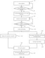
FIG. 9 is a schematic flowchart of a control method for a smoking set according to an embodiment of the present application; and -
FIG. 10 is another schematic flowchart of a control method for a smoking set according to an embodiment of the present application. - To facilitate the understanding of the present application, the present application will be described in more detail below with reference to the accompanying drawings and specific implementation. It should be noted that when an element is referred to as being "fixed to" another element, it can be directly on the other element or one or more intervening elements may be present therebetween. When an element is referred to as being "connected" to another element, it can be directly connected to the other element or one or more intervening elements may be present therebetween. As used herein, the terms "upper," "lower," "left," "right," "inner," "outer," and the like are for illustrative purposes only.
- Unless defined otherwise, all technical and scientific terms used herein have the same meaning as commonly understood by those of ordinary skill in the technical field to which this application belongs. The terms used in the specification of the present application is for the purpose of describing specific embodiments only and is not used to limit the present application. As used herein, the term "and/or" includes any and all combinations of one or more of associated listed items.
- As shown in
FIG. 1-FIG. 8 , the first embodiment of the present application provides asmoking set 10. Thesmoking set 10 includes aheater 11, acavity 12, afirst detection apparatus 13, asecond detection apparatus 14, adriving apparatus 15, acover 16, apower supply apparatus 17, a printed circuit board (PCB) 18 and a controller. - The
heater 11 is configured to heat a cigarette removably placed within thecavity 12 to generate an aerosol for smoking. The cigarette includes an aerosol generation substrate for use with thesmoking set 10 to volatilize at least one component of the aerosol generation substrate. - The aerosol generation substrate is a substrate capable of releasing volatile compounds that can form an aerosol. Such volatile compounds can be released by heating the aerosol generation substrate. The aerosol generation substrate may be solid or liquid or include solid and liquid components. The aerosol generation substrate can be loaded onto a carrier or support by means of adsorbing, coating, impregnating, or the like.
- The aerosol generation substrate may include nicotine. The aerosol generation substrate may include tobacco, e.g., may include a tobacco-containing material containing volatile tobacco flavor compounds that are released from the aerosol generation substrate when heated. Preferably, the aerosol generation substrate may include a homogenized tobacco material, e.g., deciduous tobacco. The aerosol generation substrate may include at least one aerosol generation agent, which may be any suitable known compound or mixture thereof. When in use, the compounds or mixtures thereof facilitate stable formation of the aerosol, and are substantially resistant to thermal degradation at an operating temperature of an aerosol generation system. Suitable aerosol generation agents are well known in the art and include, but are not limited to: polyols, such as triethylene glycol, 1,3-butanediol and glycerol; esters of polyols, such as glycerol monoacetate, glycerol diacetate and glycerol triacetate; and fatty acid esters of monocarboxylic acid, dicarboxylic acid or polycarboxylic acid, such as dimethyldodecanedioate and dimethyltetradecanedioate. Preferably, the aerosol generation agent is polyhydric alcohol or a mixture thereof, such as triethylene glycol, 1,3-butanediol and most preferably glycerol.
- The
heater 11 may be in a central heating manner (being in contact with the aerosol generation substrate by the periphery of a heating body) or in a peripheral heating manner (the cylindrical heating body wrapping the aerosol generation substrate), and the heater can also heat the aerosol generation substrate by means of one or more of thermal conduction, electromagnetic induction, chemical reaction, infrared action, resonance, photoelectric conversion, and photothermal conversion to generate the aerosol for smoking. - The
heater 11, which is an infrared heater, is explained below:
Theinfrared heater 11 includes a base body and an infrared electrothermal coating (not shown in the drawings). - The base body may be cylindrical, prismatic or another cylindrical shape, preferably cylindrical. A
cavity 12 is formed inside the base body, a through hole corresponding to thecavity 12 is formed in anupper cover 101 of thesmoking set 10, and the cigarette can be removed or inserted into thecavity 12. - The infrared electrothermal coating is formed on the outer surface of the base body, and the infrared electrothermal coating receives electric power from the
power supply apparatus 17 by using electrodes to generate heat, and transfers the generated heat to the cigarette inserted into thecavity 12 at least in the form of infrared radiation. - The
power supply apparatus 17 supplies electric power for operating thesmoking set 10. For example, thepower supply apparatus 17 can supply electric power to heat theheater 11 and can supply electric power needed to operate the controller. Thepower supply apparatus 17 may be, but is not limited to, a lithium iron phosphate (LiFePO4) battery. For example, thepower supply apparatus 17 may be a lithium cobalt oxide (LiCoO2) battery or a lithium titanate battery. Thepower supply apparatus 17 may be a rechargeable battery or a disposable battery. - The printed circuit board (PCB) 18 may be integrated with but not limited to the controller, a second detection circuit in the
first detection apparatus 13, and a first detection circuit in thesecond detection apparatus 14. - The controller can control the overall operation of the smoking set 10. In detail, the controller not only controls the operation of the
power supply apparatus 17 and theheater 11, but also controls the operation of other elements in the smoking set 10. In addition, the controller can determine whether the smoking set 10 can be operated by checking the status of the elements of the smoking set 10. - The controller includes at least one processor. The processor may include a logic gate array, or may include a combination of a general purpose microprocessor and a memory storing a program executable in the microprocessor. In addition, those skilled in the art should understand that the controller may include another type of hardware.
- Please refer to
FIG. 3-FIG. 5 for understanding.FIG. 3 is a schematic diagram of the smoking set 10 after theupper cover 101 is removed.FIG. 4 is a partial enlarged schematic diagram ofFIG. 3 .FIG. 5 is a schematic diagram of the first detection apparatus. - The
first detection apparatus 13 is provided downstream of thecover 16. Thefirst detection apparatus 13 includes a firstelastic sheet 131, a secondelastic sheet 132 and a second detection circuit. - One end of the first
elastic sheet 131 and one end of the secondelastic sheet 132 form a through hole for insertion or removal of the cigarette, and the controller is electrically connected to the firstelastic sheet 131 and the secondelastic sheet 132 by using the second detection circuit. - When the cigarette is not inserted into the through hole, the end of the first
elastic sheet 131 and the end of the secondelastic sheet 132 are in contact with each other, that is, embraced together, such that a close circuit through which a current passes is formed between the second detection circuit, the firstelastic sheet 131 and the secondelastic sheet 132. - When the cigarette is inserted into the through hole, the end of the first
elastic sheet 131 and the end of the secondelastic sheet 132 move to both sides, such that the end of the firstelastic sheet 131 and the end of the secondelastic sheet 132 are not in contact with each other, and an open circuit through which no current passes is formed between the second detection circuit, the firstelastic sheet 131 and the secondelastic sheet 132. - It should be noted that the upstream and downstream in this embodiment are taken as an example of an aerosol flow direction. As shown in a dashed arrow in
FIG. 2 , one end of the arrow is downstream and the other end is upstream. - Please refer to
FIG. 2 for understanding. Thesecond detection apparatus 14 includes acontact piece 141, aconductive column 142 and a first detection circuit. - Both the
contact piece 141 and theconductive column 142 are provided upstream of thecavity 12, and the controller is electrically connected to theconductive column 142 and thecontact piece 141 by using the first detection circuit. - When the cigarette inserted into the
cavity 12 is not in place, thecontact piece 141 is not in contact with theconductive column 142, such that an open circuit through which no current passes is formed between the first detection circuit, thecontact piece 141 and theconductive column 142. - When the cigarette inserted into the
cavity 12 is in place, thecontact piece 141 moves downwards to be in contact with theconductive column 142, such that a close circuit through which a current passes is formed between the first detection circuit, thecontact piece 141 and theconductive column 142. - Please refer to
FIG. 6-FIG. 8 for understanding.FIG. 6 is a schematic diagram of the smoking set 10 after theupper cover 101, a front cover and thefirst detection apparatus 13 are removed.FIG. 7 is a partial enlarged schematic diagram ofFIG. 6 .FIG. 8 is a schematic diagram of the drivingapparatus 15. - The driving
apparatus 15 is a rotary electromagnet, including ashaft core 151 and arotating rod 152. Therotating rod 152 is movably connected to ahole 161 of thecover 16, and theshaft core 151 can drive therotating rod 152 to move along the lateral direction of the smoking set 10, thereby driving thecover 16 to move along the lateral direction of the smoking set 10 to open or cover thecavity 12. - In an example, the
first detection apparatus 13 is configured to detect whether there is a cigarette to be inserted into thecavity 12, and if it is detected that there is a cigarette to be inserted into thecavity 12, output a cigarette insertion signal. - The controller is configured to acquire the cigarette insertion signal, and control, according to the cigarette insertion signal, the driving
apparatus 15 to drive thecover 16 to move relative to thecavity 12, so as to open thecavity 12 such that the cigarette can be inserted into thecavity 12. - In this example, when the cigarette is inserted into the through hole formed by one end of the first
elastic sheet 131 and one end of the secondelastic sheet 132 through theupper cover 101 of the smoking set 10, the end of the firstelastic sheet 131 and the end of the secondelastic sheet 132 moves to both sides, such that the end of the firstelastic sheet 131 and the end of the secondelastic sheet 132 are not in contact with each other, and an open circuit through which no current passes is formed between the second detection circuit, the firstelastic sheet 131 and the secondelastic sheet 132. An output end of the second detection circuit outputs a level signal (e.g., a low level signal). After acquiring the level signal, the controller can control the drivingapparatus 15 to drive thecover 16 to move relative to thecavity 12 to open thecavity 12, such that the cigarette can be inserted into thecavity 12 via the through hole formed by one end of the firstelastic sheet 131 and one end of the secondelastic sheet 132. - In an example, the
second detection apparatus 14 is configured to detect whether the cigarette inserted into thecavity 12 is in place, and if it is detected that the cigarette inserted into thecavity 12 is in place, output a cigarette insertion fulfillment signal. - The controller is further configured to acquire the cigarette insertion fulfillment signal, and control, according to the cigarette insertion fulfillment signal, the
heater 11 to start heating. - When the cigarette is inserted into the
cavity 12 via the through hole formed by one end of the firstelastic sheet 131 and one end of the secondelastic sheet 132, if the cigarette inserted into thecavity 12 is in place, thecontact piece 141 move downwards to be in contact with theconductive column 142, such that a close circuit through which a current passes is formed between the first detection circuit, thecontact piece 141 and theconductive column 142. An output end of the first detection circuit outputs a level signal (e.g., a high level signal). After acquiring the level signal, the controller controls theheater 11 to start heating. - Specifically, a temperature change curve of the
heater 11 over time generally includes a heating phase, a heat preservation phase, and a smoking phase. - In the heating phase, the temperature of the
heater 11 is raised from an initial temperature T0 (or an ambient temperature) to a preset target temperature T1. The preset target temperature T1 is set such that desired volatile compounds vaporize from the aerosol generation substrate, and undesired compounds with higher vaporization temperatures do not vaporize. Generally, the preset target temperature T1 may be 200°C-400°C. - In the heat preservation phase, the temperature of the
heater 11 is maintained at the preset target temperature T1 for a period of time, such that the aerosol generation substrate is sufficiently preheated and a smoking feeling of a user is improved. - The duration of the heating phase is t0-t1, the duration of the heat preservation phase is t1-t2, and t0-t2 is a preheating time of the
heater 11. Generally, the preheating time of theheater 11 is 5s to 30s. - In the smoking phase, the user can smoke the aerosol generated by heating of the
aerosol generation system 10. In this phase, the temperature of theheater 11 is maintained within a certain preset temperature range or at a certain preset temperature for a period of time. - When the inserted cigarette is in place, the controller controls the
heater 11 to start heating, that is, entering the heating phase. - Furthermore, the
first detection apparatus 13 is further configured to output a cigarette pull-out signal, if it is detected that the cigarette is pulled out from thecavity 12 after theheater 11 completes heating. - The controller is further configured to acquire the cigarette pull-out signal, and control, according to the cigarette pull-out signal, the driving
apparatus 15 to drive thecover 16 to move relative to thecavity 12, so as to cover thecavity 12. - After controlling the
heater 11 to start heating, if theheater 11 completes heating (e.g., after smoking is finished), and the user pulls out the cigarette from thecavity 12, the controller automatically controls the drivingapparatus 15 to drive thecover 16 to cover thecavity 12, preventing foreign objects from entering thecavity 12. - In an example, the
second detection apparatus 14 is further configured to output a cigarette insertion unfulfillment signal, if it is detected that the cigarette inserted into thecavity 12 is not in place after theheater 11 starts heating. - The controller is further configured to: acquire the cigarette insertion unfulfillment signal, and control, according to the cigarette insertion unfulfillment signal, the
heater 11 to stop heating and record a completed heating time of theheater 11. - After the
heater 11 starts heating, if the cigarette is accidentally moved (may be in any phase of the heating phase, the heat preservation phase, and the smoking phase), the cigarette will be inserted into thecavity 12 not in place, that is, thecontact piece 141 is not in contact with theconductive column 142, such that an open circuit through which no current passes is formed between the first detection circuit, thecontact piece 141 and theconductive column 142. An output end of the first detection circuit outputs a level signal (e.g., a low level signal), and after acquiring the level signal, the controller controls theheater 11 to stop heating and records the completed heating time of theheater 11. - Furthermore, the controller is further configured to: after the
heater 11 stops heating, generate a first prompt message. - The smoking set 10 further includes:
a first prompt module, configured to acquire the first prompt message to prompt the user that the position of the cigarette is abnormal. - After the
heater 11 starts heating, if the cigarette is accidentally moved, theheater 11 stops heating, and the user can be prompted that the position of the cigarette is abnormal by means of vibration, light or sound, etc., which is convenient for the user to reinsert the cigarette into thecavity 12 in place. - Furthermore, the
second detection apparatus 14 is further configured to output a cigarette reinsertion fulfillment signal, if it is detected that the cigarette is reinserted into thecavity 12 in place within a first preset time after theheater 11 stops heating. - The controller is further configured to: acquire the cigarette reinsertion fulfillment signal, calculate a remaining heating time of the
heater 11 according to the completed heating time of theheater 11, and control theheater 11 to heat according to the cigarette reinsertion fulfillment signal and the remaining heating time of theheater 11. - After the
heater 11 starts heating, if the cigarette is accidentally moved, theheater 11 stops heating. If the user reinserts the cigarette into thecavity 12 in place, the cigarette can be continuously heated, and the user does not need to repress a key to start the heating, which further simplifies the operation of the smoking set and improves the user experience. - Furthermore, the
first detection apparatus 13 is further configured to output a cigarette pull-out signal, if it is detected that the cigarette is pulled out from thecavity 12 after theheater 11 completes heating. - The controller is further configured to acquire the cigarette pull-out signal, and control, according to the cigarette pull-out signal, the driving
apparatus 15 to drive thecover 16 to move relative to thecavity 12, so as to cover thecavity 12. - After controlling the
heater 11 to restart heating, if theheater 11 completes heating (e.g., after smoking is finished), and the user pulls out the cigarette from thecavity 12, the controller automatically controls the drivingapparatus 15 to drive thecover 16 to cover thecavity 12, preventing foreign objects from entering thecavity 12. - Furthermore, the
first detection apparatus 13 is further configured to output a cigarette pull-out signal, if it is detected that the cigarette is pulled out from thecavity 12 after theheater 11 stops heating. - The controller is further configured to acquire the cigarette pull-out signal, and control, according to the cigarette pull-out signal, the driving
apparatus 15 to drive thecover 16 to move relative to thecavity 12, so as to cover thecavity 12. - During the process that the
heater 11 starts heating, if the cigarette is accidentally moved (causing theheater 11 to stop heating) and pulled out from thecavity 12, the controller automatically controls the drivingapparatus 15 to drive thecover 16 to cover thecavity 12. - Furthermore, the controller is further configured to: after the
cover 16 covers thecavity 12, within a second preset time, stop controlling the drivingapparatus 15 to drive thecover 16 to move relative to thecavity 12 so as to open thecavity 12. - After the cigarette is accidentally pulled out from the
cavity 12 and thecover 16 covers thecavity 12, thecover 16 no longer opens thecavity 12 within the second preset time (in this case, the controller can receive the cigarette insertion signal output by thefirst detection apparatus 13 but does not process the same, or the controller does not receive the cigarette insertion signal output by the first detection apparatus 13). - Furthermore, the controller is further configured to: after the
cover 16 covers thecavity 12, generate a second prompt message. - The smoking set 10 further includes:
a second prompt module, configured to acquire the second prompt message to prompt the user to replace the cigarette. - After the cigarette is accidentally pulled out from the
cavity 12 and thecover 16 covers thecavity 12, the user can be prompted to replace the cigarette by means of vibration, light or sound, etc., preventing the user from reinserting the old cigarette, and ensuring the mouth feeling of the user during use. - As shown in
FIG. 9 , the second embodiment of the present application provides a control method for a smoking set. For the specific structure of the smoking set 10, reference can be made to the content of the first embodiment, which will not be repeated here. - The control method for a smoking set includes:
- Step S10: Acquire a cigarette insertion signal output by a first detection apparatus.
- Step S11: Control, according to the cigarette insertion signal, a driving apparatus to drive a cover to move relative to a cavity, so as to open the cavity such that the cigarette can be inserted into the cavity.
- Specifically, when the cigarette is inserted into the through hole formed by one end of the first
elastic sheet 131 and one end of the secondelastic sheet 132 through theupper cover 101 of the smoking set 10, the end of the firstelastic sheet 131 and the end of the secondelastic sheet 132 moves to both sides, such that the end of the firstelastic sheet 131 and the end of the secondelastic sheet 132 are not in contact with each other, and an open circuit through which no current passes is formed between the second detection circuit, the firstelastic sheet 131 and the secondelastic sheet 132. An output end of the second detection circuit outputs a level signal (e.g., a low level signal). After acquiring the level signal, the controller can control the drivingapparatus 15 to drive thecover 16 to move relative to thecavity 12 to open thecavity 12, such that the cigarette can be inserted into thecavity 12 via the through hole formed by one end of the firstelastic sheet 131 and one end of the secondelastic sheet 132. - In an example, the method further includes (not shown in drawings):
- Step S12: Acquire a cigarette insertion fulfillment signal output by a second detection apparatus.
- Step S13: Control a heater to start heating according to the cigarette insertion fulfillment signal.
- Specifically, when the cigarette is inserted into the
cavity 12 via the through hole formed by one end of the firstelastic sheet 131 and one end of the secondelastic sheet 132, if the cigarette inserted into thecavity 12 is in place, thecontact piece 141 move downwards to be in contact with theconductive column 142, such that a close circuit through which a current passes is formed between the first detection circuit, thecontact piece 141 and theconductive column 142. An output end of the first detection circuit outputs a level signal (e.g., a high level signal). After acquiring the level signal, the controller controls theheater 11 to start heating. - A temperature change curve of the
heater 11 over time generally includes a heating phase, a heat preservation phase, and a smoking phase. - In the heating phase, the temperature of the
heater 11 is raised from an initial temperature T0 (or an ambient temperature) to a preset target temperature T1. The preset target temperature T1 is set such that desired volatile compounds vaporize from the aerosol generation substrate, and undesired compounds with higher vaporization temperatures do not vaporize. Generally, the preset target temperature T1 may be 200°C-400°C. - In the heat preservation phase, the temperature of the
heater 11 is maintained at the preset target temperature T1 for a period of time, such that the aerosol generation substrate is sufficiently preheated and a smoking feeling of a user is improved. - The duration of the heating phase is t0-t1, the duration of the heat preservation phase is t1-t2, and t0-t2 is a preheating time of the
heater 11. Generally, the preheating time of theheater 11 is 5s to 30s. - In the smoking phase, the user can smoke the aerosol generated by heating of the
aerosol generation system 10. In this phase, the temperature of theheater 11 is maintained within a certain preset temperature range or at a certain preset temperature for a period of time. - When the inserted cigarette is in place, the controller controls the
heater 11 to start heating, that is, entering the heating phase. - In an example, the method further includes (not shown in drawings):
- Step S1411: Acquire a cigarette pull-out signal output by the first detection apparatus.
- Step S1412: Control, according to the cigarette pull-out signal, the driving apparatus to drive the cover to move relative to the cavity, so as to cover the cavity.
- Specifically, after controlling the
heater 11 to start heating, if theheater 11 completes heating (e.g., after smoking is finished), the user pulls out the cigarette from thecavity 12, the controller automatically controls the drivingapparatus 15 to drive thecover 16 to cover thecavity 12, preventing foreign objects from entering thecavity 12. - In an example, the method further includes (not shown in drawings):
- Step S1421: Acquire a cigarette insertion unfulfillment signal output by the second detection apparatus.
- Step S1422: Control, according to the cigarette insertion unfulfillment signal, the heater to stop heating and record a completed heating time of the heater.
- Specifically, after the
heater 11 starts heating, if the cigarette is accidentally moved (can be in any phase of the heating phase, the heat preservation phase, and the smoking phase), the cigarette inserted into thecavity 12 will be not in place, that is, thecontact piece 141 is not in contact with theconductive column 142, such that an open circuit through which no current passes is formed between the first detection circuit, thecontact piece 141 and theconductive column 142. An output end of the first detection circuit outputs a level signal (e.g., a low level signal), and after acquiring the level signal, the controller controls theheater 11 to stop heating and records the completed heating time of theheater 11. - Furthermore, if the
heater 11 stops heating, the user can be prompted that the position of the cigarette is abnormal by means of vibration, light or sound, etc., which is convenient for the user to reinsert the cigarette into thecavity 12 in place. - In an example, the method further includes (not shown in drawings):
- Step S1511: Acquire a cigarette reinsertion fulfillment signal output by the second detection apparatus.
- Step S1512: Calculate a remaining heating time of the heater according to the completed heating time of the heater.
- Step S1513: Control the heater to heat according to the cigarette reinsertion fulfillment signal and the remaining heating time of the heater.
- Specifically, because the cigarette is accidentally moved, the
heater 11 stops heating. If the user reinserts the cigarette into thecavity 12 in place, the cigarette can be continuously heated, and the user does not need to repress a key to start the heating, which further simplifies the operation of the smoking set and improves the user experience. - Furthermore, after controlling the
heater 11 to restart heating, if theheater 11 completes heating (e.g., after smoking is finished), and the user pulls out the cigarette from the cavity 12 (that is, acquiring the cigarette pull-out signal output by the first detection apparatus 13), the controller automatically controls the drivingapparatus 15 to drive thecover 16 to cover thecavity 12, preventing foreign objects from entering thecavity 12. - In an example, the method further includes (not shown in drawings):
- Step S1521: Acquire the cigarette pull-out signal output by the first detection apparatus.
- Step S1522: Control, according to the cigarette pull-out signal, the driving apparatus to drive the cover to move relative to the cavity, so as to cover the cavity.
- Specifically, during the process that the
heater 11 starts heating, if the cigarette is accidentally moved (causing theheater 11 to stop heating) and pulled out from thecavity 12, the controller automatically controls the drivingapparatus 15 to drive thecover 16 to cover thecavity 12. - In an example, the method further includes (not shown in drawings):
Step S1523: After the cover covers the cavity, within a preset time, stop controlling the driving apparatus to drive the cover to move relative to the cavity, so as to open the cavity. - Specifically, after the cigarette is accidentally pulled out from the
cavity 12 and thecover 16 covers thecavity 12, thecover 16 no longer opens thecavity 12 within the preset time (in this case, the controller can receive the cigarette insertion signal output by thefirst detection apparatus 13 but does not process the same, or the controller does not receive the cigarette insertion signal output by the first detection apparatus 13). - Furthermore, after the cigarette is accidentally pulled out from the
cavity 12 and thecover 16 covers thecavity 12, the user can be prompted to replace the cigarette by means of vibration, light or sound, etc., preventing the user from reinserting the old cigarette, and ensuring the mouth feeling of the user during use. - An overall control process of the smoking set 10 will be described below with reference to
FIG. 10 : - Step S21: Insert a cigarette.
- Step S22: Detect whether the cigarette is inserted.
- Specifically, when the cigarette is not inserted, the end of the first
elastic sheet 131 and the end of the secondelastic sheet 132 are in contact with each other, that is, embraced together, such that a close circuit through which a current passes is formed between the second detection circuit, the firstelastic sheet 131 and the secondelastic sheet 132. - When the cigarette is inserted, the end of the first
elastic sheet 131 and the end of the secondelastic sheet 132 move to both sides, such that the end of the firstelastic sheet 131 and the end of the secondelastic sheet 132 are not in contact with each other, and an open circuit through which no current passes is formed between the second detection circuit, the firstelastic sheet 131 and the secondelastic sheet 132. - Step S23: If it is detected that the cigarette is inserted, an electromagnet drives the cover to open the cavity, and otherwise, the detection is continued.
- Step S24: After the cavity is opened, the cigarette can be continuously inserted.
- Step S25: Detect whether the inserted cigarette is in place.
- Specifically, when the cigarette inserted into the
cavity 12 is not in place, thecontact piece 141 is not in contact with theconductive column 142, such that an open circuit through which no current passes is formed between the first detection circuit, thecontact piece 141 and theconductive column 142. - When the cigarette inserted into the
cavity 12 is in place, thecontact piece 141 moves downwards to be in contact with theconductive column 142, such that a close circuit through which a current passes is formed between the first detection circuit, thecontact piece 141 and theconductive column 142. - Step S26: When the cigarette inserted into the
cavity 12 is in place, the controller controls the heater to start heating. - Step S271, Step S28, Step S29: If heating of the cigarette is completed and the cigarette is pulled out, the electromagnet drives the cover to close the cavity.
- Step S272, step S273, step S28, step S29: If the cigarette is abnormally removed from an insertion position, the controller controls the heater to stop heating; in this case, if the cigarette is pulled out, the electromagnet drives the cover to close the cavity.
- It should be noted that preferred embodiments of the present application are given in the specification and accompanying drawings thereof, but the present application can be embodied in many different forms and is not limited to the embodiments described in the specification, and these embodiments are not intended as additional limitations on the present application. These embodiments are provided for the purpose of achieving a more thorough and complete understanding of the disclosure of the present application. Furthermore, the above technical features continue to be combined with each other to form various embodiments not listed above, all of which are considered to be within the scope of the specification of the present application. Furthermore, it will be apparent to those of ordinary skill in the art that modifications or variations may be made in light of the above description, and all such modifications and variations should fall within the scope of the appended claims.
Claims (17)
- A smoking set, comprising a cavity and a heater, wherein the heater is configured to heat a cigarette removably placed within the cavity to generate an aerosol for smoking, and further comprising:a cover;a driving apparatus, configured to drive the cover to move relative to the cavity, so as to open or cover the cavity;a first detection apparatus, provided downstream of the cover, the first detection apparatus being configured to detect whether there is a cigarette to be inserted into the cavity, and if it is detected that there is a cigarette to be inserted into the cavity, output a cigarette insertion signal; anda controller, configured to acquire the cigarette insertion signal, and control, according to the cigarette insertion signal, the driving apparatus to drive the cover to move relative to the cavity, so as to open the cavity such that the cigarette can be inserted into the cavity.
- The smoking set according to claim 1, wherein the smoking set further comprises:a second detection apparatus, configured to detect whether the cigarette is inserted into the cavity in place, and if it is detected that the cigarette inserted into the cavity is in place, output a cigarette insertion fulfillment signal; andthe controller is further configured to acquire the cigarette insertion fulfillment signal, and control the heater to start heating according to the cigarette insertion fulfillment signal.
- The smoking set according to claim 2, whereinthe second detection apparatus is further configured to output a cigarette insertion unfulfillment signal, if it is detected that the cigarette inserted into the cavity is not in place after the heater starts heating; andthe controller is further configured to: acquire the cigarette insertion unfulfillment signal, and control, according to the cigarette insertion unfulfillment signal, the heater to stop heating and record a completed heating time of the heater.
- The smoking set according to claim 3, whereinthe second detection apparatus is further configured to output a cigarette reinsertion fulfillment signal, if it is detected that the cigarette reinserted into the cavity is in place within a first preset time after the heater stops heating; andthe controller is further configured to: acquire the cigarette reinsertion fulfillment signal, calculate a remaining heating time of the heater according to the completed heating time of the heater, and control the heater to heat according to the cigarette reinsertion fulfillment signal and the remaining heating time of the heater.
- The smoking set according to claim 3, whereinthe first detection apparatus is further configured to output a cigarette pull-out signal, if it is detected that the cigarette is pulled out from the cavity after the heater stops heating; andthe controller is further configured to acquire the cigarette pull-out signal, and control, according to the cigarette pull-out signal, the driving apparatus to drive the cover to move relative to the cavity, so as to cover the cavity.
- The smoking set according to claim 5, wherein
the controller is further configured to: after the cover covers the cavity, within a second preset time, stop controlling the driving apparatus to drive the cover to move relative to the cavity, so as to open the cavity. - The smoking set according to claim 2 or 4, whereinthe first detection apparatus is further configured to output a cigarette pull-out signal, if it is detected that the cigarette is pulled out from the cavity after the heater completes heating; andthe controller is further configured to acquire the cigarette pull-out signal, and control, according to the cigarette pull-out signal, the driving apparatus to drive the cover to move relative to the cavity, so as to cover the cavity.
- The smoking set according to any one of claims 2-7, wherein the second detection apparatus comprises a contact piece, a conductive column and a first detection circuit;both the contact piece and the conductive column are provided upstream of the cavity, and the controller is electrically connected to the conductive column and the contact piece by using the first detection circuit;when the cigarette inserted into the cavity is not in place, the contact piece is not in contact with the conductive column, such that an open circuit through which no current passes is formed between the first detection circuit, the contact piece and the conductive column; andwhen the cigarette inserted into the cavity is in place, the contact piece is in contact with the conductive column, such that a close circuit through which a current passes is formed between the first detection circuit, the contact piece and the conductive column.
- The smoking set according to any one of claims 1-8, wherein the first detection apparatus comprises a first elastic sheet, a second elastic sheet and a second detection circuit;one end of the first elastic sheet and one end of the second elastic sheet form a through hole for insertion or removal of the cigarette, and the controller is electrically connected to the first elastic sheet and the second elastic sheet by using the second detection circuit;when the cigarette is not inserted into the through hole, the end of the first elastic sheet and the end of the second elastic sheet are in contact with each other, such that a close circuit through which a current passes is formed between the second detection circuit, the first elastic sheet and the second elastic sheet; andwhen the cigarette is inserted into the through hole, the end of the first elastic sheet and the end of the second elastic sheet are not in contact with each other, such that an open circuit through which no current passes is formed between the second detection circuit, the first elastic sheet and the second elastic sheet.
- The smoking set according to any one of claims 1-9, wherein the driving apparatus comprises a rotary electromagnet, and the rotary electromagnet drives the cover to move along the lateral direction of the smoking set.
- A control method for the smoking set according to any one of claims 1-10, comprising:acquiring a cigarette insertion signal output by a first detection apparatus; andcontrolling, according to the cigarette insertion signal, a driving apparatus to drive a cover to move relative to a cavity, so as to open the cavity such that the cigarette can be inserted into the cavity.
- The method according to claim 11, further comprising:acquiring a cigarette insertion fulfillment signal output by a second detection apparatus; andcontrolling a heater to start heating according to the cigarette insertion fulfillment signal.
- The method according to claim 12, further comprising:acquiring a cigarette insertion unfulfillment signal output by the second detection apparatus; andcontrolling, according to the cigarette insertion unfulfillment signal, the heater to stop heating and recording a completed heating time of the heater.
- The method according to claim 13, further comprising:acquiring a cigarette reinsertion fulfillment signal output by the second detection apparatus;calculating a remaining heating time of the heater according to the completed heating time of the heater; andcontrolling the heater to heat according to the cigarette reinsertion fulfillment signal and the remaining heating time of the heater.
- The method according to claim 13, further comprising:acquiring a cigarette pull-out signal output by the first detection apparatus; andcontrolling, according to the cigarette pull-out signal, the driving apparatus to drive the cover to move relative to the cavity, so as to cover the cavity.
- The method according to claim 15, further comprising:
after the cover covers the cavity, within a preset time, stopping controlling the driving apparatus to drive the cover to move relative to the cavity, so as to open the cavity. - The method according to claim 12 or 14, further comprising:acquiring a cigarette pull-out signal output by the first detection apparatus; andcontrolling, according to the cigarette pull-out signal, the driving apparatus to drive the cover to move relative to the cavity, so as to cover the cavity.
Applications Claiming Priority (2)
| Application Number | Priority Date | Filing Date | Title |
|---|---|---|---|
| CN202010291641.2A CN113519908B (en) | 2020-04-14 | 2020-04-14 | Smoking device and control method thereof |
| PCT/CN2021/086914 WO2021208908A1 (en) | 2020-04-14 | 2021-04-13 | Smoking set and control method therefor |
Publications (3)
| Publication Number | Publication Date |
|---|---|
| EP4136993A1 true EP4136993A1 (en) | 2023-02-22 |
| EP4136993A4 EP4136993A4 (en) | 2023-10-25 |
| EP4136993B1 EP4136993B1 (en) | 2024-08-28 |
Family
ID=78085255
Family Applications (1)
| Application Number | Title | Priority Date | Filing Date |
|---|---|---|---|
| EP21788207.5A Active EP4136993B1 (en) | 2020-04-14 | 2021-04-13 | Smoking set and control method therefor |
Country Status (4)
| Country | Link |
|---|---|
| US (1) | US20230157362A1 (en) |
| EP (1) | EP4136993B1 (en) |
| CN (1) | CN113519908B (en) |
| WO (1) | WO2021208908A1 (en) |
Families Citing this family (2)
| Publication number | Priority date | Publication date | Assignee | Title |
|---|---|---|---|---|
| US20250113870A1 (en) * | 2022-01-27 | 2025-04-10 | Jt International Sa | Inhalation Device |
| WO2024103361A1 (en) * | 2022-11-17 | 2024-05-23 | 思摩尔国际控股有限公司 | Aerosol forming apparatus and control method therefor |
Family Cites Families (17)
| Publication number | Priority date | Publication date | Assignee | Title |
|---|---|---|---|---|
| JPH0638596U (en) * | 1992-11-02 | 1994-05-24 | 瀬川 隆昭 | Automatic fire ashtray device |
| JP2003159044A (en) * | 2001-11-27 | 2003-06-03 | Toyoda Gosei Co Ltd | Ash tray on vehicle |
| JP2005125823A (en) * | 2003-10-21 | 2005-05-19 | Nifco Inc | Automatic ashtray device |
| KR101169564B1 (en) * | 2009-12-14 | 2012-07-31 | 주식회사바벨 | Ashtray for cigarette with flame detector |
| US9427022B2 (en) * | 2012-03-12 | 2016-08-30 | UpToke, LLC | Electronic vaporizing device and methods for use |
| WO2018057911A1 (en) * | 2016-09-23 | 2018-03-29 | Mc10, Inc. | Methods and systems for connecting a power source to mobile devices |
| CN207136245U (en) * | 2017-09-01 | 2018-03-27 | 南通烟滤嘴有限责任公司 | A kind of electronic cigarette smoking set |
| CN107692317B (en) * | 2017-09-11 | 2019-07-16 | 云南中烟工业有限责任公司 | A kind of device that can light or heat automatically cigarette |
| CN108143006B (en) * | 2018-01-12 | 2023-12-29 | 深圳市康泓威科技有限公司 | Automatically controlled heating and non-combustible electronic cigarette and control method thereof |
| GB201805263D0 (en) * | 2018-03-29 | 2018-05-16 | Nicoventures Trading Ltd | Apparatus for generating aerosol from an aerosolisable medium, an article of aerosolisable medium and a method of operating an aerosol generating apparatus |
| CN110403241B (en) * | 2018-04-28 | 2021-02-23 | 深圳御烟实业有限公司 | Aerosol-generating device and system |
| CN108552611A (en) * | 2018-07-05 | 2018-09-21 | 云南中烟工业有限责任公司 | Electronic smoking set is arranged with sensor airflow channel separation in a kind of electronic cigarette gas channel |
| CN108523251A (en) * | 2018-07-19 | 2018-09-14 | 余坚 | A kind of safety cigarette based on light guide techniques |
| CN209202153U (en) | 2018-11-29 | 2019-08-06 | 湖南中烟工业有限责任公司 | Intelligent baking low temperature smoking set |
| CN210275898U (en) * | 2019-06-04 | 2020-04-10 | 湖南中烟工业有限责任公司 | Low-temperature smoking set with sliding dustproof cover |
| EP4076068A1 (en) * | 2019-12-20 | 2022-10-26 | JT International SA | Aerosol generation device with optical code detector |
| KR20230098847A (en) * | 2020-12-07 | 2023-07-04 | 필립모리스 프로덕츠 에스.에이. | Aerosol-generating device with a movable upper cover and a lower cover |
-
2020
- 2020-04-14 CN CN202010291641.2A patent/CN113519908B/en active Active
-
2021
- 2021-04-13 US US17/919,249 patent/US20230157362A1/en active Pending
- 2021-04-13 WO PCT/CN2021/086914 patent/WO2021208908A1/en not_active Ceased
- 2021-04-13 EP EP21788207.5A patent/EP4136993B1/en active Active
Also Published As
| Publication number | Publication date |
|---|---|
| EP4136993B1 (en) | 2024-08-28 |
| US20230157362A1 (en) | 2023-05-25 |
| CN113519908B (en) | 2025-10-10 |
| CN113519908A (en) | 2021-10-22 |
| EP4136993A4 (en) | 2023-10-25 |
| WO2021208908A1 (en) | 2021-10-21 |
Similar Documents
| Publication | Publication Date | Title |
|---|---|---|
| CN113439881A (en) | Aerosol generating device and control method thereof | |
| EP4059366B1 (en) | Aerosol generation device, and control method thereof | |
| EP4136993B1 (en) | Smoking set and control method therefor | |
| EP4140340B1 (en) | Aerosol generation apparatus and control method therefor | |
| US20230096771A1 (en) | Aerosol Generation Device Providing Enhanced Vaping Experience | |
| EP4091474A1 (en) | Smoking set | |
| EP4623730A1 (en) | Aerosol generating apparatus and control method therefor | |
| TWI891794B (en) | Aerosol generation device, aerosol generation system, control method and storage medium | |
| EP4225081A1 (en) | Aerosol generation device | |
| US20250351883A1 (en) | Aerosol Generation Device | |
| US20250344771A1 (en) | Aerosol Generation Device | |
| KR102729531B1 (en) | Aerosol generator with auto pop-up function of holder | |
| US20250288019A1 (en) | Aerosol Generation Device | |
| JP2023552447A (en) | Aerosol generator with movable upstream and downstream covers | |
| CN221265244U (en) | Aerosol generating device | |
| JP2025520313A (en) | Aerosol generating device | |
| EP4586839A1 (en) | Aerosol generating device and associated operating method | |
| CN120052619A (en) | Heating control method of atomizing equipment and atomizing equipment | |
| EP4604769A1 (en) | Aerosol generating assembly | |
| WO2024246058A1 (en) | An aerosol generation device | |
| WO2025242476A1 (en) | Aerosol provision device | |
| CN117981927A (en) | Aerosol generating device and control method thereof |
Legal Events
| Date | Code | Title | Description |
|---|---|---|---|
| STAA | Information on the status of an ep patent application or granted ep patent |
Free format text: STATUS: THE INTERNATIONAL PUBLICATION HAS BEEN MADE |
|
| PUAI | Public reference made under article 153(3) epc to a published international application that has entered the european phase |
Free format text: ORIGINAL CODE: 0009012 |
|
| STAA | Information on the status of an ep patent application or granted ep patent |
Free format text: STATUS: REQUEST FOR EXAMINATION WAS MADE |
|
| 17P | Request for examination filed |
Effective date: 20221111 |
|
| AK | Designated contracting states |
Kind code of ref document: A1 Designated state(s): AL AT BE BG CH CY CZ DE DK EE ES FI FR GB GR HR HU IE IS IT LI LT LU LV MC MK MT NL NO PL PT RO RS SE SI SK SM TR |
|
| DAV | Request for validation of the european patent (deleted) | ||
| DAX | Request for extension of the european patent (deleted) | ||
| REG | Reference to a national code |
Ref country code: DE Ref legal event code: R079 Free format text: PREVIOUS MAIN CLASS: A24F0047000000 Ipc: A24F0040400000 Ref country code: DE Ref legal event code: R079 Ref document number: 602021018035 Country of ref document: DE Free format text: PREVIOUS MAIN CLASS: A24F0047000000 Ipc: A24F0040400000 |
|
| A4 | Supplementary search report drawn up and despatched |
Effective date: 20230921 |
|
| RIC1 | Information provided on ipc code assigned before grant |
Ipc: A24F 40/40 20200101AFI20230915BHEP |
|
| GRAP | Despatch of communication of intention to grant a patent |
Free format text: ORIGINAL CODE: EPIDOSNIGR1 |
|
| STAA | Information on the status of an ep patent application or granted ep patent |
Free format text: STATUS: GRANT OF PATENT IS INTENDED |
|
| RIC1 | Information provided on ipc code assigned before grant |
Ipc: A24F 40/51 20200101ALN20240308BHEP Ipc: A24F 40/20 20200101ALN20240308BHEP Ipc: A24F 40/40 20200101AFI20240308BHEP |
|
| INTG | Intention to grant announced |
Effective date: 20240326 |
|
| GRAS | Grant fee paid |
Free format text: ORIGINAL CODE: EPIDOSNIGR3 |
|
| GRAA | (expected) grant |
Free format text: ORIGINAL CODE: 0009210 |
|
| STAA | Information on the status of an ep patent application or granted ep patent |
Free format text: STATUS: THE PATENT HAS BEEN GRANTED |
|
| AK | Designated contracting states |
Kind code of ref document: B1 Designated state(s): AL AT BE BG CH CY CZ DE DK EE ES FI FR GB GR HR HU IE IS IT LI LT LU LV MC MK MT NL NO PL PT RO RS SE SI SK SM TR |
|
| REG | Reference to a national code |
Ref country code: CH Ref legal event code: EP |
|
| REG | Reference to a national code |
Ref country code: DE Ref legal event code: R096 Ref document number: 602021018035 Country of ref document: DE |
|
| REG | Reference to a national code |
Ref country code: IE Ref legal event code: FG4D |
|
| REG | Reference to a national code |
Ref country code: LT Ref legal event code: MG9D |
|
| PG25 | Lapsed in a contracting state [announced via postgrant information from national office to epo] |
Ref country code: NO Free format text: LAPSE BECAUSE OF FAILURE TO SUBMIT A TRANSLATION OF THE DESCRIPTION OR TO PAY THE FEE WITHIN THE PRESCRIBED TIME-LIMIT Effective date: 20241128 |
|
| REG | Reference to a national code |
Ref country code: AT Ref legal event code: MK05 Ref document number: 1716948 Country of ref document: AT Kind code of ref document: T Effective date: 20240828 |
|
| PG25 | Lapsed in a contracting state [announced via postgrant information from national office to epo] |
Ref country code: NL Free format text: LAPSE BECAUSE OF FAILURE TO SUBMIT A TRANSLATION OF THE DESCRIPTION OR TO PAY THE FEE WITHIN THE PRESCRIBED TIME-LIMIT Effective date: 20240828 Ref country code: PL Free format text: LAPSE BECAUSE OF FAILURE TO SUBMIT A TRANSLATION OF THE DESCRIPTION OR TO PAY THE FEE WITHIN THE PRESCRIBED TIME-LIMIT Effective date: 20240828 Ref country code: GR Free format text: LAPSE BECAUSE OF FAILURE TO SUBMIT A TRANSLATION OF THE DESCRIPTION OR TO PAY THE FEE WITHIN THE PRESCRIBED TIME-LIMIT Effective date: 20241129 Ref country code: PT Free format text: LAPSE BECAUSE OF FAILURE TO SUBMIT A TRANSLATION OF THE DESCRIPTION OR TO PAY THE FEE WITHIN THE PRESCRIBED TIME-LIMIT Effective date: 20241230 Ref country code: FI Free format text: LAPSE BECAUSE OF FAILURE TO SUBMIT A TRANSLATION OF THE DESCRIPTION OR TO PAY THE FEE WITHIN THE PRESCRIBED TIME-LIMIT Effective date: 20240828 |
|
| PG25 | Lapsed in a contracting state [announced via postgrant information from national office to epo] |
Ref country code: BG Free format text: LAPSE BECAUSE OF FAILURE TO SUBMIT A TRANSLATION OF THE DESCRIPTION OR TO PAY THE FEE WITHIN THE PRESCRIBED TIME-LIMIT Effective date: 20240828 |
|
| PG25 | Lapsed in a contracting state [announced via postgrant information from national office to epo] |
Ref country code: LV Free format text: LAPSE BECAUSE OF FAILURE TO SUBMIT A TRANSLATION OF THE DESCRIPTION OR TO PAY THE FEE WITHIN THE PRESCRIBED TIME-LIMIT Effective date: 20240828 |
|
| REG | Reference to a national code |
Ref country code: NL Ref legal event code: MP Effective date: 20240828 |
|
| PG25 | Lapsed in a contracting state [announced via postgrant information from national office to epo] |
Ref country code: IS Free format text: LAPSE BECAUSE OF FAILURE TO SUBMIT A TRANSLATION OF THE DESCRIPTION OR TO PAY THE FEE WITHIN THE PRESCRIBED TIME-LIMIT Effective date: 20241228 Ref country code: AT Free format text: LAPSE BECAUSE OF FAILURE TO SUBMIT A TRANSLATION OF THE DESCRIPTION OR TO PAY THE FEE WITHIN THE PRESCRIBED TIME-LIMIT Effective date: 20240828 |
|
| PG25 | Lapsed in a contracting state [announced via postgrant information from national office to epo] |
Ref country code: HR Free format text: LAPSE BECAUSE OF FAILURE TO SUBMIT A TRANSLATION OF THE DESCRIPTION OR TO PAY THE FEE WITHIN THE PRESCRIBED TIME-LIMIT Effective date: 20240828 |
|
| PG25 | Lapsed in a contracting state [announced via postgrant information from national office to epo] |
Ref country code: ES Free format text: LAPSE BECAUSE OF FAILURE TO SUBMIT A TRANSLATION OF THE DESCRIPTION OR TO PAY THE FEE WITHIN THE PRESCRIBED TIME-LIMIT Effective date: 20240828 Ref country code: RS Free format text: LAPSE BECAUSE OF FAILURE TO SUBMIT A TRANSLATION OF THE DESCRIPTION OR TO PAY THE FEE WITHIN THE PRESCRIBED TIME-LIMIT Effective date: 20241128 |
|
| PG25 | Lapsed in a contracting state [announced via postgrant information from national office to epo] |
Ref country code: RS Free format text: LAPSE BECAUSE OF FAILURE TO SUBMIT A TRANSLATION OF THE DESCRIPTION OR TO PAY THE FEE WITHIN THE PRESCRIBED TIME-LIMIT Effective date: 20241128 Ref country code: PT Free format text: LAPSE BECAUSE OF FAILURE TO SUBMIT A TRANSLATION OF THE DESCRIPTION OR TO PAY THE FEE WITHIN THE PRESCRIBED TIME-LIMIT Effective date: 20241230 Ref country code: PL Free format text: LAPSE BECAUSE OF FAILURE TO SUBMIT A TRANSLATION OF THE DESCRIPTION OR TO PAY THE FEE WITHIN THE PRESCRIBED TIME-LIMIT Effective date: 20240828 Ref country code: NO Free format text: LAPSE BECAUSE OF FAILURE TO SUBMIT A TRANSLATION OF THE DESCRIPTION OR TO PAY THE FEE WITHIN THE PRESCRIBED TIME-LIMIT Effective date: 20241128 Ref country code: NL Free format text: LAPSE BECAUSE OF FAILURE TO SUBMIT A TRANSLATION OF THE DESCRIPTION OR TO PAY THE FEE WITHIN THE PRESCRIBED TIME-LIMIT Effective date: 20240828 Ref country code: LV Free format text: LAPSE BECAUSE OF FAILURE TO SUBMIT A TRANSLATION OF THE DESCRIPTION OR TO PAY THE FEE WITHIN THE PRESCRIBED TIME-LIMIT Effective date: 20240828 Ref country code: IS Free format text: LAPSE BECAUSE OF FAILURE TO SUBMIT A TRANSLATION OF THE DESCRIPTION OR TO PAY THE FEE WITHIN THE PRESCRIBED TIME-LIMIT Effective date: 20241228 Ref country code: HR Free format text: LAPSE BECAUSE OF FAILURE TO SUBMIT A TRANSLATION OF THE DESCRIPTION OR TO PAY THE FEE WITHIN THE PRESCRIBED TIME-LIMIT Effective date: 20240828 Ref country code: GR Free format text: LAPSE BECAUSE OF FAILURE TO SUBMIT A TRANSLATION OF THE DESCRIPTION OR TO PAY THE FEE WITHIN THE PRESCRIBED TIME-LIMIT Effective date: 20241129 Ref country code: FI Free format text: LAPSE BECAUSE OF FAILURE TO SUBMIT A TRANSLATION OF THE DESCRIPTION OR TO PAY THE FEE WITHIN THE PRESCRIBED TIME-LIMIT Effective date: 20240828 Ref country code: ES Free format text: LAPSE BECAUSE OF FAILURE TO SUBMIT A TRANSLATION OF THE DESCRIPTION OR TO PAY THE FEE WITHIN THE PRESCRIBED TIME-LIMIT Effective date: 20240828 Ref country code: BG Free format text: LAPSE BECAUSE OF FAILURE TO SUBMIT A TRANSLATION OF THE DESCRIPTION OR TO PAY THE FEE WITHIN THE PRESCRIBED TIME-LIMIT Effective date: 20240828 Ref country code: AT Free format text: LAPSE BECAUSE OF FAILURE TO SUBMIT A TRANSLATION OF THE DESCRIPTION OR TO PAY THE FEE WITHIN THE PRESCRIBED TIME-LIMIT Effective date: 20240828 |
|
| PG25 | Lapsed in a contracting state [announced via postgrant information from national office to epo] |
Ref country code: SM Free format text: LAPSE BECAUSE OF FAILURE TO SUBMIT A TRANSLATION OF THE DESCRIPTION OR TO PAY THE FEE WITHIN THE PRESCRIBED TIME-LIMIT Effective date: 20240828 Ref country code: DK Free format text: LAPSE BECAUSE OF FAILURE TO SUBMIT A TRANSLATION OF THE DESCRIPTION OR TO PAY THE FEE WITHIN THE PRESCRIBED TIME-LIMIT Effective date: 20240828 Ref country code: RO Free format text: LAPSE BECAUSE OF FAILURE TO SUBMIT A TRANSLATION OF THE DESCRIPTION OR TO PAY THE FEE WITHIN THE PRESCRIBED TIME-LIMIT Effective date: 20240828 |
|
| P01 | Opt-out of the competence of the unified patent court (upc) registered |
Free format text: CASE NUMBER: APP_11094/2025 Effective date: 20250306 |
|
| PG25 | Lapsed in a contracting state [announced via postgrant information from national office to epo] |
Ref country code: EE Free format text: LAPSE BECAUSE OF FAILURE TO SUBMIT A TRANSLATION OF THE DESCRIPTION OR TO PAY THE FEE WITHIN THE PRESCRIBED TIME-LIMIT Effective date: 20240828 |
|
| PG25 | Lapsed in a contracting state [announced via postgrant information from national office to epo] |
Ref country code: CZ Free format text: LAPSE BECAUSE OF FAILURE TO SUBMIT A TRANSLATION OF THE DESCRIPTION OR TO PAY THE FEE WITHIN THE PRESCRIBED TIME-LIMIT Effective date: 20240828 |
|
| PG25 | Lapsed in a contracting state [announced via postgrant information from national office to epo] |
Ref country code: IT Free format text: LAPSE BECAUSE OF FAILURE TO SUBMIT A TRANSLATION OF THE DESCRIPTION OR TO PAY THE FEE WITHIN THE PRESCRIBED TIME-LIMIT Effective date: 20240828 Ref country code: SK Free format text: LAPSE BECAUSE OF FAILURE TO SUBMIT A TRANSLATION OF THE DESCRIPTION OR TO PAY THE FEE WITHIN THE PRESCRIBED TIME-LIMIT Effective date: 20240828 |
|
| REG | Reference to a national code |
Ref country code: DE Ref legal event code: R097 Ref document number: 602021018035 Country of ref document: DE |
|
| PLBE | No opposition filed within time limit |
Free format text: ORIGINAL CODE: 0009261 |
|
| STAA | Information on the status of an ep patent application or granted ep patent |
Free format text: STATUS: NO OPPOSITION FILED WITHIN TIME LIMIT |
|
| PGFP | Annual fee paid to national office [announced via postgrant information from national office to epo] |
Ref country code: DE Payment date: 20250411 Year of fee payment: 5 |
|
| PGFP | Annual fee paid to national office [announced via postgrant information from national office to epo] |
Ref country code: GB Payment date: 20250417 Year of fee payment: 5 |
|
| PGFP | Annual fee paid to national office [announced via postgrant information from national office to epo] |
Ref country code: FR Payment date: 20250429 Year of fee payment: 5 |
|
| 26N | No opposition filed |
Effective date: 20250530 |
|
| PG25 | Lapsed in a contracting state [announced via postgrant information from national office to epo] |
Ref country code: SE Free format text: LAPSE BECAUSE OF FAILURE TO SUBMIT A TRANSLATION OF THE DESCRIPTION OR TO PAY THE FEE WITHIN THE PRESCRIBED TIME-LIMIT Effective date: 20240828 |
|
| REG | Reference to a national code |
Ref country code: CH Ref legal event code: H13 Free format text: ST27 STATUS EVENT CODE: U-0-0-H10-H13 (AS PROVIDED BY THE NATIONAL OFFICE) Effective date: 20251125 |
|
| PG25 | Lapsed in a contracting state [announced via postgrant information from national office to epo] |
Ref country code: LU Free format text: LAPSE BECAUSE OF NON-PAYMENT OF DUE FEES Effective date: 20250413 |
|
| PG25 | Lapsed in a contracting state [announced via postgrant information from national office to epo] |
Ref country code: MC Free format text: LAPSE BECAUSE OF FAILURE TO SUBMIT A TRANSLATION OF THE DESCRIPTION OR TO PAY THE FEE WITHIN THE PRESCRIBED TIME-LIMIT Effective date: 20240828 |
|
| REG | Reference to a national code |
Ref country code: BE Ref legal event code: MM Effective date: 20250430 |
|
| PG25 | Lapsed in a contracting state [announced via postgrant information from national office to epo] |
Ref country code: BE Free format text: LAPSE BECAUSE OF NON-PAYMENT OF DUE FEES Effective date: 20250430 |
|
| PG25 | Lapsed in a contracting state [announced via postgrant information from national office to epo] |
Ref country code: CH Free format text: LAPSE BECAUSE OF NON-PAYMENT OF DUE FEES Effective date: 20250430 |
|
| PG25 | Lapsed in a contracting state [announced via postgrant information from national office to epo] |
Ref country code: IE Free format text: LAPSE BECAUSE OF NON-PAYMENT OF DUE FEES Effective date: 20250413 |