EP4136958A1 - Apparatus and method for adjusting faceplate of feeder for agricultural vehicle - Google Patents
Apparatus and method for adjusting faceplate of feeder for agricultural vehicle Download PDFInfo
- Publication number
- EP4136958A1 EP4136958A1 EP22190689.4A EP22190689A EP4136958A1 EP 4136958 A1 EP4136958 A1 EP 4136958A1 EP 22190689 A EP22190689 A EP 22190689A EP 4136958 A1 EP4136958 A1 EP 4136958A1
- Authority
- EP
- European Patent Office
- Prior art keywords
- feeder
- faceplate
- threaded shaft
- agricultural vehicle
- header
- Prior art date
- Legal status (The legal status is an assumption and is not a legal conclusion. Google has not performed a legal analysis and makes no representation as to the accuracy of the status listed.)
- Granted
Links
Images


Classifications
-
- A—HUMAN NECESSITIES
- A01—AGRICULTURE; FORESTRY; ANIMAL HUSBANDRY; HUNTING; TRAPPING; FISHING
- A01D—HARVESTING; MOWING
- A01D41/00—Combines, i.e. harvesters or mowers combined with threshing devices
- A01D41/12—Details of combines
- A01D41/14—Mowing tables
- A01D41/16—Devices for coupling mowing tables to conveyors
-
- A—HUMAN NECESSITIES
- A01—AGRICULTURE; FORESTRY; ANIMAL HUSBANDRY; HUNTING; TRAPPING; FISHING
- A01D—HARVESTING; MOWING
- A01D41/00—Combines, i.e. harvesters or mowers combined with threshing devices
- A01D41/06—Combines with headers
-
- A—HUMAN NECESSITIES
- A01—AGRICULTURE; FORESTRY; ANIMAL HUSBANDRY; HUNTING; TRAPPING; FISHING
- A01D—HARVESTING; MOWING
- A01D61/00—Elevators or conveyors for binders or combines
- A01D61/008—Elevators or conveyors for binders or combines for longitudinal conveying, especially for combines
Definitions
- the present invention relates to agricultural harvesters. More specifically, the present invention relates to an apparatus and method for adjusting a position of a faceplate of a feeder for an agricultural vehicle, such as a combine harvester.
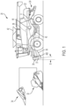
- FIG. 1 depicts a self-propelled agricultural combine 20.
- Combine 20 has a front end to which a header 32 can be connected.
- Header 32 is commonly referred to as a grain header and is typically utilized for harvesting smaller grains, such as, but not limited to, wheat and soybeans.
- Another well-known header 34 is shown, which is a corn header. Corn header 34 can also be connected to combine 20. Headers 32 and 34, as well as other headers (not shown), are configured to be interchangeably mounted on the front end of a feeder 36 of combine 20 for configuring combine 20 to harvest a particular crop.
- the crops harvested by a header will be gathered up by the header 32/34 and conveyed by feeder 36 (also referred to in the art as a feederhouse) rearwardly and upwardly into the body of the combine 20, for processing by a threshing system 38.
- System 38 is operable for threshing and separating grain from larger elements of crop material, such as stems, leaves, cobs and larger fragments of pods, such that the grain will fall into a cleaning system 40, which will further process or clean smaller elements of crop residue from the grain, and the grain will be conveyed to a grain tank 42 or other collector.
- Headers 32 and 34 are interchangeably attached to a faceplate 37 on the free end of feeder 36.
- headers 32/34 include couplers for releasably mounting to a coupling 39 on faceplate 37.
- a feeder faceplate angle B can be adjusted to accommodate the particular header 32/34. Angle B may also be adjusted due to crop conditions, ground conditions, and more. Angle B may be defined as the fore/aft pitch angle of the feeder.
- feeder faceplate 37 rotates along a transverse axis passing through feeder 36 (e.g., an axis passing through the page of FIG. 1 ), and feeder faceplate angle B represents rotation about that axis.
- a feeder for an agricultural vehicle includes a feeder body defining a hollow interior space for receiving crop material from a header of the agricultural vehicle, a faceplate that is movably mounted to the feeder body, and a scissor jack assembly that is configured for rotating the faceplate with respect to the feeder body to adjust a fore-aft angle of the faceplate relative to the feeder body.
- the faceplate is configured to be removably coupled to the header of the agricultural vehicle.
- the feeder is shown schematically in FIGs. 2A-3B .
- forward when used in connection with the agricultural harvester and/or components thereof are usually determined with reference to the direction of forward operative travel of the harvester, but again, they should not be construed as limiting.
- longitudinal and “transverse” are determined with reference to the fore-and-aft direction of the agricultural harvester and are equally not to be construed as limiting.
- upstream and “downstream” are determined with reference to the crop flow stream arrows shown in FIG. 1 .
- feeder 36 includes a body 35 having a hollow interior for receiving crop material from the header 32/34.
- Faceplate 37 is mounted to the forward end of feeder body 35. Faceplate 37 may not be permanently mounted to feeder body 35, however, it is not readily and easily removable from feeder body 35.
- Faceplate 37 includes one or more couplings 39 that are configured to be releasably connected to mating couplings on header 32/34, as was described above. Couplings 39 may be located anywhere on faceplate 37, and are not limited to that which is shown. Couplings 39 may be hinges, bolts, hooks, fasteners, or any other couplings known in the agricultural vehicle arts.
- Faceplate 37 is mounted to the top side of faceplate 37 by a hinge 200, such that faceplate 37 is capable of being rotated about hinge 200 (see curved arrow) with respect to feeder body 35. As was noted above, it may be necessary to rotate faceplate 37 about hinge 200 to accommodate various header styles or to adjust the position of a header relative to the ground. Rotating the faceplate 37 changes the feeder faceplate angle 'B' as well as the distance between bottom side 37a of feeder 37 (as measured along fore-aft axis 'C').
- a scissor jack assembly 400 (referred to hereinafter as assembly 400) is configured to rotate faceplate 37 with respect to feeder body 35.
- Assembly 400 is mounted at the bottom side 37a of faceplate 37 at a location (i) between the forward side of feeder body 35 and the rear side of faceplate 37, and (ii) beneath hinge 200.
- Assembly 400 extends transversely along axis D ( FIG. 2A ). It should be understood that location of assembly 400 is not limited to that which is shown. For example, assembly 400 may be positioned closer to the top end of faceplate 37 and hinge 200 may be positioned at the bottom end of faceplate 37, or, assembly 400 could extend vertically (as opposed to transversely).
- assembly 400 comprises a threaded shaft 402 including threaded segments (i.e., mechanical threads) extending along its length as well as non-threaded segments.
- the segments of threaded shaft 402 may be interconnected by couplings 422, sleeves, bolts, etc.
- a first scissor jack 404a is mounted to one side of threaded shaft 402, and a second scissor jack 404b is mounted to an opposing side of threaded shaft 402.
- Scissor jacks 404a and 404b are substantially identical, and may be referred to herein either individually or collectively as jack(s) 404. Although only one jack 404 will be described hereinafter, it should be understood that foregoing description also applies to the other jack 404.
- Jack 404 includes two connected arms 405a and 405b each having one end that is pivotably connected to a hinge 208. Hinge 208 pivotably interconnects jack 404 with faceplate 37. As best shown in FIG. 4 , hinge 208 optionally includes two knuckles defining an open passageway through which a rod (not shown) passes. The rod is connected to faceplate 37. Hinge 208 can pivot about the rod. The other end of arms 405a and 405b are pivotably mounted to pins 407a and 407b, respectively. Each pin 407 includes a threaded opening that is threadedly connected to threads of threaded shaft 402, such that rotation of threaded shaft 402 causes translation of pins 407.
- Jack 404 also includes two connected arms 406a and 406b each having one end that is pivotably connected to a hinge 409. Hinge 409 pivotably interconnects jack 404 with feeder body 35. As best shown in FIG. 4 , hinge 409 optionally includes one knuckle defining an open passageway through which a rod (not shown) passes. The rod is connected to feeder body 35. Hinge 209 can pivot about the rod. The other end of arms 406a and 406b are pivotably mounted to pins 407a and 407b, respectively. Pins 407a and 407b may be referred to collectively as pins 407.
- Pin 407a is connected to a righthand thread on threaded shaft 402, and pin 407b is connected to a left-hand thread on threaded shaft 402, or vice versa, such that pins 407a and 407b translate along axis D in opposite directions upon rotating threaded shaft 402.
- pins 407 of jack 404a translate toward each other, and, pins 407 of jack 404b also translate toward each other.
- Jacks 404a and 404b move in concert (simultaneously) with each other because they are connected to a common threaded shaft 402.
- arms 405a/b and 406a/b rotate inwardly along a transverse axis D and extend outwardly along the fore-aft axis C. Consequently, starting from the partially extended (i.e., rotated) position or state of assembly 400 shown in FIGs.
- pins 407 of jack 404a translate away from each other, and, pins 407 of jack 404b also translate away from each other.
- arms 405a/b and 406a/b rotate outwardly along a transverse axis D and extend inwardly along the fore-aft axis C. Consequently, starting from the fully extended (i.e., rotated) state of assembly 400' shown in FIGs.
- the end 37a of faceplate 37 rotates toward feeder body 35 and the feeder faceplate angle 'B' decreases until the end 37a of faceplate 37 reaches the partially extended (i.e., rotated) position 400 shown in FIGs. 2A / 2B .
- further rotation is possible until the feeder faceplate angle 'B' reaches a value of zero.
- the free end of threaded shaft 402 may be hexagonal, square, or, more generally, non-circular, as viewed in cross-section.
- the free end of threaded shaft 402 may be rotated manually by a wrench or driver, for example.
- threaded shaft 402 may be rotated in an automated fashion by a motor 410 that is controlled by an operator in the cab of combine 20, for example.
- Motor 410, or a transmission connected thereto, may be self-locking to prevent inadvertent rotation of faceplate 37.
- Motor 410 may be powered electrically or hydraulically, for example.
- lock 415 in the form of a plate may be connected to threaded shaft 402 to prevent inadvertent rotation of threaded shaft 402. More particularly, lock 415 includes a first opening 417 having a shape that is complementary to the non-circular cross-sectional shape of the free end of threaded shaft 402 such that threaded shaft 402 and first opening 417 are connected in a non-rotatable manner. Lock 415 includes a second opening for receiving a threaded fastener 420. Fastener 420 can be connected to faceplate 37, feeder 36, or another fixed point on combine 20. It should be understood that rotation of threaded shaft 402, and consequent movement of jacks 404, is prevented when lock 415 is mounted to threaded shaft 402 and fastener 420 is connected to a fixed point.
- lock 415 may vary from that which is shown.
- Lock 415 can be any device that is configured to resist rotation of threaded shaft 402.
- Lock 415 may be a collar, collet, fastener, clip, pin, clamp, and so forth. For that reason, lock 415 may also be referred to herein as a locking device or "means for locking" the threaded shaft 402.
- Assembly 400 may vary from that which is shown and described. It should also be understood that the details of jack 404 can vary, and different styles of jacks are known to those skilled in the art (e.g., scissor, jackscrew, house, floor, bottle, inflatable, air hydraulic, strand, farm, etc.).
- assembly 400 shown in FIGs. 2B and 3B may simply represent a motor having a protruding piston, wherein the motor is mounted to the feeder body 35 and the piston is mounted to faceplate 37. The motor may be powered electrically or hydraulically, for example.
- assembly 400 may be generally referred to herein as a "means for moving" faceplate with respect to feeder body 35.
- the scissor jack assembly 400 can include one jack 404 or two (or more) interconnected jacks 404, as shown.
- the scissor jack assembly 404 may be positioned on either the top or the bottom of the feeder.
- the shaft 402 may be on the top, middle or bottom side of the feeder or at any position in between.
- Other alternatives and modifications are described above.
Landscapes
- Life Sciences & Earth Sciences (AREA)
- Environmental Sciences (AREA)
- Harvester Elements (AREA)
- Automatic Assembly (AREA)
- Automobile Manufacture Line, Endless Track Vehicle, Trailer (AREA)
Abstract
Description
- The present invention relates to agricultural harvesters. More specifically, the present invention relates to an apparatus and method for adjusting a position of a faceplate of a feeder for an agricultural vehicle, such as a combine harvester.
-
FIG. 1 depicts a self-propelledagricultural combine 20. Combine 20 has a front end to which aheader 32 can be connected.Header 32 is commonly referred to as a grain header and is typically utilized for harvesting smaller grains, such as, but not limited to, wheat and soybeans. Another well-knownheader 34 is shown, which is a corn header.Corn header 34 can also be connected to combine 20.Headers feeder 36 of combine 20 for configuring combine 20 to harvest a particular crop. - In operation, the crops harvested by a header, such as
header 32 orheader 34, will be gathered up by theheader 32/34 and conveyed by feeder 36 (also referred to in the art as a feederhouse) rearwardly and upwardly into the body of thecombine 20, for processing by athreshing system 38.System 38 is operable for threshing and separating grain from larger elements of crop material, such as stems, leaves, cobs and larger fragments of pods, such that the grain will fall into acleaning system 40, which will further process or clean smaller elements of crop residue from the grain, and the grain will be conveyed to agrain tank 42 or other collector. The larger elements of crop material will be propelled rearwardly through arear end 22 of the body of combine 20 by a rapidly rotatingbeater 44, and into an inlet opening of aspreader 24, as generally denoted by arrow A, inFIG. 1 . Further details ofcombine 20 may be described inU.S. Patent No. 8,010,262 to Blue Leaf IP Inc. (the '262 Patent). It is noted, however, that combine 20 ofFIG. 1 departs from the combine shown in the '262 Patent. And, althoughFIG. 1 is described in the background section, it should be understood that thecombine 20 is not admitted prior art. -
Headers faceplate 37 on the free end offeeder 36. Specifically,headers 32/34 include couplers for releasably mounting to acoupling 39 onfaceplate 37. A feeder faceplate angle B can be adjusted to accommodate theparticular header 32/34. Angle B may also be adjusted due to crop conditions, ground conditions, and more. Angle B may be defined as the fore/aft pitch angle of the feeder. Stated differently,feeder faceplate 37 rotates along a transverse axis passing through feeder 36 (e.g., an axis passing through the page ofFIG. 1 ), and feeder faceplate angle B represents rotation about that axis. - In view of the foregoing, it would be desirable to provide a simple and easy way for an end-user to adjust angle B of
faceplate 37 offeeder 36. - According to one aspect of the invention, a feeder for an agricultural vehicle includes a feeder body defining a hollow interior space for receiving crop material from a header of the agricultural vehicle, a faceplate that is movably mounted to the feeder body, and a scissor jack assembly that is configured for rotating the faceplate with respect to the feeder body to adjust a fore-aft angle of the faceplate relative to the feeder body. The faceplate is configured to be removably coupled to the header of the agricultural vehicle.
- The above-mentioned and other features and advantages of this invention, and the manner of attaining them, will become more apparent and the invention will be better understood by reference to the following description of an embodiment of the invention taken in conjunction with the accompanying drawings, wherein:
-
FIG. 1 is a side view of an embodiment of an agricultural harvester in the form of a combine, and two different headers that are each configured to be mounted to a feeder of the combine. -
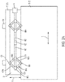
FIG. 2A is a bottom plan view of the feeder of the combine ofFIG. 1 , wherein a faceplate of the feeder is shown partially extended by a scissor jack assembly. -
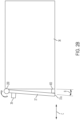
FIG. 2B is a side elevation view of the feeder ofFIG. 2A having a partially extended faceplate. -
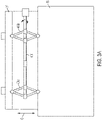
FIG. 3A is another bottom plan view of the feeder of the combine ofFIG. 1 , wherein a faceplate of the feeder is shown fully extended by the scissor jack assembly. -
FIG. 3B is a side elevation view of the feeder ofFIG. 3A having a fully extended faceplate. -
FIG. 4 is an isometric view of the scissor jack assembly of the combine ofFIG. 1 . - The feeder is shown schematically in
FIGs. 2A-3B . - Corresponding reference characters indicate corresponding parts throughout the several views. The exemplification set out herein illustrates an embodiment of the invention, in one form, and such exemplification is not to be construed as limiting the scope of the invention in any manner.
- Inasmuch as various components and features of harvesters are of well-known design, construction, and operation to those skilled in the art, the details of such components and their operations will not generally be discussed in significant detail unless considered of pertinence to the present invention or desirable for purposes of better understanding.
- In the drawings, like numerals refer to like items, certain elements and features may be labeled or marked on a representative basis without each like element or feature necessarily being individually shown, labeled, or marked, and certain elements are labeled and marked in only some, but not all, of the drawing figures.
- The terms "forward" (or fore), "rearward" (or rear or aft), "left" and "right", when used in connection with the agricultural harvester and/or components thereof are usually determined with reference to the direction of forward operative travel of the harvester, but again, they should not be construed as limiting. The terms "longitudinal" and "transverse" are determined with reference to the fore-and-aft direction of the agricultural harvester and are equally not to be construed as limiting. The terms "upstream" and "downstream" are determined with reference to the crop flow stream arrows shown in
FIG. 1 . - Referring now to the drawings, and more particularly to
FIGs. 1 ,2A and2B ,feeder 36 includes a body 35 having a hollow interior for receiving crop material from theheader 32/34. Faceplate 37 is mounted to the forward end of feeder body 35. Faceplate 37 may not be permanently mounted to feeder body 35, however, it is not readily and easily removable from feeder body 35. Faceplate 37 includes one ormore couplings 39 that are configured to be releasably connected to mating couplings onheader 32/34, as was described above.Couplings 39 may be located anywhere onfaceplate 37, and are not limited to that which is shown.Couplings 39 may be hinges, bolts, hooks, fasteners, or any other couplings known in the agricultural vehicle arts. - Faceplate 37 is mounted to the top side of
faceplate 37 by ahinge 200, such thatfaceplate 37 is capable of being rotated about hinge 200 (see curved arrow) with respect to feeder body 35. As was noted above, it may be necessary to rotatefaceplate 37 abouthinge 200 to accommodate various header styles or to adjust the position of a header relative to the ground. Rotating thefaceplate 37 changes the feeder faceplate angle 'B' as well as the distance betweenbottom side 37a of feeder 37 (as measured along fore-aft axis 'C'). - A scissor jack assembly 400 (referred to hereinafter as assembly 400) is configured to rotate
faceplate 37 with respect to feeder body 35.Assembly 400 is mounted at thebottom side 37a offaceplate 37 at a location (i) between the forward side of feeder body 35 and the rear side offaceplate 37, and (ii) beneathhinge 200.Assembly 400 extends transversely along axis D (FIG. 2A ). It should be understood that location ofassembly 400 is not limited to that which is shown. For example,assembly 400 may be positioned closer to the top end offaceplate 37 andhinge 200 may be positioned at the bottom end offaceplate 37, or,assembly 400 could extend vertically (as opposed to transversely). - Turning now to
FIGs. 2A and4 ,assembly 400 comprises a threadedshaft 402 including threaded segments (i.e., mechanical threads) extending along its length as well as non-threaded segments. The segments of threadedshaft 402 may be interconnected bycouplings 422, sleeves, bolts, etc. Afirst scissor jack 404a is mounted to one side of threadedshaft 402, and asecond scissor jack 404b is mounted to an opposing side of threadedshaft 402. Scissor jacks 404a and 404b are substantially identical, and may be referred to herein either individually or collectively as jack(s) 404. Although only one jack 404 will be described hereinafter, it should be understood that foregoing description also applies to the other jack 404. - Jack 404 includes two
connected arms faceplate 37. As best shown inFIG. 4 , hinge 208 optionally includes two knuckles defining an open passageway through which a rod (not shown) passes. The rod is connected tofaceplate 37. Hinge 208 can pivot about the rod. The other end ofarms pins shaft 402, such that rotation of threadedshaft 402 causes translation of pins 407. - Jack 404 also includes two
connected arms hinge 409.Hinge 409 pivotably interconnects jack 404 with feeder body 35. As best shown inFIG. 4 , hinge 409 optionally includes one knuckle defining an open passageway through which a rod (not shown) passes. The rod is connected to feeder body 35. Hinge 209 can pivot about the rod. The other end ofarms pins Pins Pin 407a is connected to a righthand thread on threadedshaft 402, andpin 407b is connected to a left-hand thread on threadedshaft 402, or vice versa, such thatpins shaft 402. - More particularly, in one rotational direction of threaded
shaft 402, pins 407 ofjack 404a translate toward each other, and, pins 407 ofjack 404b also translate toward each other.Jacks shaft 402. When pins 407 of jack 404 translate toward each other,arms 405a/b and 406a/b rotate inwardly along a transverse axis D and extend outwardly along the fore-aft axis C. Consequently, starting from the partially extended (i.e., rotated) position or state ofassembly 400 shown inFIGs. 2A /2B , theend 37a offaceplate 37 rotates further away from feeder body 35 and the feeder faceplate angle 'B' increases until theend 37a offaceplate 37 reaches the fully extended (i.e., rotated) position or state of assembly 400' shown inFIGs. 3A /3B . - In an opposite rotational direction of threaded
shaft 402, pins 407 ofjack 404a translate away from each other, and, pins 407 ofjack 404b also translate away from each other. When pins 407 of jack 404 translate away from each other,arms 405a/b and 406a/b rotate outwardly along a transverse axis D and extend inwardly along the fore-aft axis C. Consequently, starting from the fully extended (i.e., rotated) state of assembly 400' shown inFIGs. 3A /3B , theend 37a offaceplate 37 rotates toward feeder body 35 and the feeder faceplate angle 'B' decreases until theend 37a offaceplate 37 reaches the partially extended (i.e., rotated)position 400 shown inFIGs. 2A /2B . Although not shown, further rotation is possible until the feeder faceplate angle 'B' reaches a value of zero. - The free end of threaded
shaft 402 may be hexagonal, square, or, more generally, non-circular, as viewed in cross-section. The free end of threadedshaft 402 may be rotated manually by a wrench or driver, for example. Alternatively, threadedshaft 402 may be rotated in an automated fashion by amotor 410 that is controlled by an operator in the cab ofcombine 20, for example.Motor 410, or a transmission connected thereto, may be self-locking to prevent inadvertent rotation offaceplate 37.Motor 410 may be powered electrically or hydraulically, for example. - Turning to
FIG. 4 , if threadedshaft 402 is operated manually, then aremovable lock 415 in the form of a plate may be connected to threadedshaft 402 to prevent inadvertent rotation of threadedshaft 402. More particularly,lock 415 includes afirst opening 417 having a shape that is complementary to the non-circular cross-sectional shape of the free end of threadedshaft 402 such that threadedshaft 402 andfirst opening 417 are connected in a non-rotatable manner.Lock 415 includes a second opening for receiving a threadedfastener 420.Fastener 420 can be connected tofaceplate 37,feeder 36, or another fixed point oncombine 20. It should be understood that rotation of threadedshaft 402, and consequent movement of jacks 404, is prevented whenlock 415 is mounted to threadedshaft 402 andfastener 420 is connected to a fixed point. - It should be understood that
lock 415 may vary from that which is shown.Lock 415 can be any device that is configured to resist rotation of threadedshaft 402.Lock 415 may be a collar, collet, fastener, clip, pin, clamp, and so forth. For that reason, lock 415 may also be referred to herein as a locking device or "means for locking" the threadedshaft 402. -
Assembly 400 may vary from that which is shown and described. It should also be understood that the details of jack 404 can vary, and different styles of jacks are known to those skilled in the art (e.g., scissor, jackscrew, house, floor, bottle, inflatable, air hydraulic, strand, farm, etc.). In lieu of using jacks,assembly 400 shown inFIGs. 2B and3B may simply represent a motor having a protruding piston, wherein the motor is mounted to the feeder body 35 and the piston is mounted tofaceplate 37. The motor may be powered electrically or hydraulically, for example. In view of all of the different devices described herein that may be used to rotatefaceplate 37 with respect to feeder body 35,assembly 400 may be generally referred to herein as a "means for moving" faceplate with respect to feeder body 35. - While this invention has been described with respect to at least one embodiment, the present invention can be further modified within the spirit and scope of this disclosure. For example, the
scissor jack assembly 400 can include one jack 404 or two (or more) interconnected jacks 404, as shown. The scissor jack assembly 404 may be positioned on either the top or the bottom of the feeder. Theshaft 402 may be on the top, middle or bottom side of the feeder or at any position in between. Other alternatives and modifications are described above. - This application is therefore intended to cover any variations, uses, or adaptations of the invention using its general principles. Further, this application is intended to cover such departures from the present disclosure as come within known or customary practice in the art to which this invention pertains and which fall within the limits of the appended claims.
Claims (14)
- A feeder (36) for an agricultural vehicle (20), said feeder comprising:a feeder body (35) defining a hollow interior space for receiving crop material from a header (32/34) of the agricultural vehicle,a faceplate (37) that is movably mounted to the feeder body (35), wherein the faceplate (37) is configured to be removably coupled to the header (32/34) of the agricultural vehicle,characterized in that the feeder (36) further comprises a scissor jack assembly (400) that is configured for rotating the faceplate (37) with respect to the feeder body (35) to adjust a fore-aft angle (B) of the faceplate (37) relative to the feeder body (35).
- The feeder of claim 1, wherein the feeder (36) further comprises a coupler (39) mounted to the faceplate (37) that is configured to be mounted to the header (32/34) of the agricultural vehicle.
- The feeder of claim 1 or 2, wherein the feeder (36) further comprises a hinge (200) for pivotably connecting the faceplate (37) to the feeder body (35).
- The feeder of any one of the preceding claims, wherein the scissor jack assembly (400) is configured for rotating the faceplate (37) about a transverse axis of the feeder or agricultural vehicle (20) for adjusting the fore-aft angle (B) of the faceplate (37).
- The feeder of any one of the preceding claims, wherein the feeder (36) further comprises a hinge (200) for pivotably connecting the faceplate (37) to the feeder body (35), wherein the hinge (200) is positioned at an elevation above the scissor jack assembly (400).
- The feeder of any one of the preceding claims, wherein the scissor jack assembly (400) comprises a threaded shaft (402), and at least one scissor jack (404) that is connected to the threaded shaft (402), wherein rotation of the threaded shaft (402) causes movement of the scissor jack (404) which causes the faceplate (37) to rotate with respect to the feeder body (35).
- The feeder of claim 6, wherein the feeder (36) further comprises two scissor jacks (404) mounted to the threaded shaft (402), wherein rotation of the threaded shaft (402) causes movement of said two scissor jacks (404).
- The feeder of claim 6 or claim 7, wherein the feeder (36) further comprises a motor (410) for rotating said threaded shaft (402).
- The feeder of any one of claims 6-8, wherein the feeder (36) further comprises a lock (415) that is removably connected to the threaded shaft (402) for preventing rotation of the threaded shaft (402).
- The feeder of claim 9, wherein the lock (415) comprises an opening (417) for receiving the threaded shaft (402) in a non-rotatable manner, and a fastener (420) for mounting to one of the feeder body (35), the faceplate (37) and a fixed point on the agricultural vehicle to prevent rotation of the threaded shaft (402).
- The feeder of claim 10, wherein the opening (417) has a shape that is complimentary to a cross-sectional shape of the threaded shaft (402).
- A subassembly comprising the header (32/34) mounted to the feeder (36) of any one of the preceding claims.
- An agricultural vehicle comprising the feeder of any one of the preceding claims.
- A combine harvester comprising the feeder of any one of the preceding claims.
Applications Claiming Priority (1)
| Application Number | Priority Date | Filing Date | Title |
|---|---|---|---|
| US17/406,514 US12102038B2 (en) | 2021-08-19 | 2021-08-19 | Apparatus and method for adjusting faceplate of feeder for agricultural vehicle |
Publications (2)
| Publication Number | Publication Date |
|---|---|
| EP4136958A1 true EP4136958A1 (en) | 2023-02-22 |
| EP4136958B1 EP4136958B1 (en) | 2024-11-20 |
Family
ID=82943283
Family Applications (1)
| Application Number | Title | Priority Date | Filing Date |
|---|---|---|---|
| EP22190689.4A Active EP4136958B1 (en) | 2021-08-19 | 2022-08-17 | Apparatus and method for adjusting faceplate of feeder for agricultural vehicle |
Country Status (3)
| Country | Link |
|---|---|
| US (1) | US12102038B2 (en) |
| EP (1) | EP4136958B1 (en) |
| BR (1) | BR102022015514A2 (en) |
Citations (5)
| Publication number | Priority date | Publication date | Assignee | Title |
|---|---|---|---|---|
| EP0448844A1 (en) * | 1990-03-27 | 1991-10-02 | New Holland Belgium N.V. | Combine harvester feeder house for mounting header on base unit |
| US5918448A (en) * | 1997-02-06 | 1999-07-06 | Agco Corporation | Combine header lateral tilt assembly |
| US6330782B1 (en) * | 1999-04-01 | 2001-12-18 | New Holland North America, Inc. | Front drum adjustment mechanism for a feederhouse on an agricultural combine |
| US8010262B2 (en) | 2009-10-21 | 2011-08-30 | Cnh America Llc | Apparatus and method for automatically controlling the settings of an adjustable crop residue spreader of an agricultural combine |
| US20160270290A1 (en) * | 2015-03-17 | 2016-09-22 | Agco Corporation | Header position sensing system for an agricultural harvester |
Family Cites Families (12)
| Publication number | Priority date | Publication date | Assignee | Title |
|---|---|---|---|---|
| US5460460A (en) * | 1994-03-01 | 1995-10-24 | The Serco Corporation | Scissors lift dock leveler |
| RU2157613C1 (en) | 1999-03-12 | 2000-10-20 | Открытое акционерное общество "Тульский комбайновый завод" | Fodder harvesting combine |
| DE19916645B4 (en) | 1999-04-14 | 2005-12-29 | Deere & Company, Moline | conveyor assembly |
| AUPQ990000A0 (en) | 2000-09-01 | 2000-09-28 | Schutt, Craig James | Combine harvesters |
| US20080256914A1 (en) * | 2007-04-23 | 2008-10-23 | Ricketts Jonathan E | Method and device for automatically coupling a combine feeder interface and a combine header via a stationary gearbox |
| BE1022551B1 (en) * | 2014-11-27 | 2016-05-31 | Cnh Industrial Belgium Nv | HARVESTER FOR USE IN AGRICULTURE |
| BE1022622B1 (en) * | 2015-03-27 | 2016-06-17 | Cnh Industrial Belgium Nv | Mower mounting frame |
| DE102015107090A1 (en) | 2015-05-06 | 2016-11-10 | Claas Selbstfahrende Erntemaschinen Gmbh | Cutting angle adjustment of a cutting unit |
| GB201607568D0 (en) * | 2016-04-29 | 2016-06-15 | Agco Do Brazil Com E Ind Ltda | Harvester header pitch adjustment apparatus |
| US10524422B2 (en) | 2017-04-28 | 2020-01-07 | Deere & Company | Harvesting head constant force assembly |
| CN207977932U (en) | 2018-01-23 | 2018-10-16 | 常州佳讯光电系统工程有限公司 | A kind of roof photovoltaic support structure of quick adjusting angle |
| CN208413728U (en) | 2018-07-10 | 2019-01-22 | 刘文成 | Novel agricultural machinery overhaul support frame |
-
2021
- 2021-08-19 US US17/406,514 patent/US12102038B2/en active Active
-
2022
- 2022-08-05 BR BR102022015514-3A patent/BR102022015514A2/en unknown
- 2022-08-17 EP EP22190689.4A patent/EP4136958B1/en active Active
Patent Citations (5)
| Publication number | Priority date | Publication date | Assignee | Title |
|---|---|---|---|---|
| EP0448844A1 (en) * | 1990-03-27 | 1991-10-02 | New Holland Belgium N.V. | Combine harvester feeder house for mounting header on base unit |
| US5918448A (en) * | 1997-02-06 | 1999-07-06 | Agco Corporation | Combine header lateral tilt assembly |
| US6330782B1 (en) * | 1999-04-01 | 2001-12-18 | New Holland North America, Inc. | Front drum adjustment mechanism for a feederhouse on an agricultural combine |
| US8010262B2 (en) | 2009-10-21 | 2011-08-30 | Cnh America Llc | Apparatus and method for automatically controlling the settings of an adjustable crop residue spreader of an agricultural combine |
| US20160270290A1 (en) * | 2015-03-17 | 2016-09-22 | Agco Corporation | Header position sensing system for an agricultural harvester |
Also Published As
| Publication number | Publication date |
|---|---|
| US12102038B2 (en) | 2024-10-01 |
| EP4136958B1 (en) | 2024-11-20 |
| US20230058333A1 (en) | 2023-02-23 |
| BR102022015514A2 (en) | 2023-03-07 |
Similar Documents
| Publication | Publication Date | Title |
|---|---|---|
| US10820519B2 (en) | Agricultural chopper with linked counter knives and shear bar | |
| US8051633B2 (en) | Cutterbar adjustment support for a crop harvesting header | |
| US10820509B2 (en) | Foldable corn head | |
| US9723783B2 (en) | Folding auger assembly coupler | |
| EP3659421B1 (en) | Harvesting header with adjustable transverse auger | |
| US11622505B2 (en) | Agricultural header with constant reel to cutter relationship | |
| EP3406130A1 (en) | Agricultural machine with sectional header | |
| EP4009769B1 (en) | Tool-less folding divider for combine head | |
| EP4136958B1 (en) | Apparatus and method for adjusting faceplate of feeder for agricultural vehicle | |
| US9609805B2 (en) | Folding auger assembly for an agricultural harvester | |
| DE19916645B4 (en) | conveyor assembly | |
| US20220256769A1 (en) | Feederhouse assemblies, agricultural harvesters, and methods of connecting harvesting headers to agricultural harvesters | |
| US20240373776A1 (en) | Position control of a segmented agricultural work assembly | |
| US11744181B2 (en) | Feederhouse assemblies having biased lock pins, agricultural harvesters, and related methods | |
| US20250151660A1 (en) | Sieve assembly for separating grains from plant residual material | |
| US11140826B2 (en) | Feederhouse assembly having a rotational shaft with fluid passages | |
| US20250144960A1 (en) | Work vehicle with mounting system for differently sized wheels | |
| US20240237578A1 (en) | Feeder housing with torque stops for agricultural vehicle | |
| CA3072370C (en) | Agricultural header with constant reel to cutter relationship | |
| EP3714677B1 (en) | Header transport system |
Legal Events
| Date | Code | Title | Description |
|---|---|---|---|
| PUAI | Public reference made under article 153(3) epc to a published international application that has entered the european phase |
Free format text: ORIGINAL CODE: 0009012 |
|
| STAA | Information on the status of an ep patent application or granted ep patent |
Free format text: STATUS: THE APPLICATION HAS BEEN PUBLISHED |
|
| AK | Designated contracting states |
Kind code of ref document: A1 Designated state(s): AL AT BE BG CH CY CZ DE DK EE ES FI FR GB GR HR HU IE IS IT LI LT LU LV MC MK MT NL NO PL PT RO RS SE SI SK SM TR |
|
| STAA | Information on the status of an ep patent application or granted ep patent |
Free format text: STATUS: REQUEST FOR EXAMINATION WAS MADE |
|
| 17P | Request for examination filed |
Effective date: 20230822 |
|
| RBV | Designated contracting states (corrected) |
Designated state(s): AL AT BE BG CH CY CZ DE DK EE ES FI FR GB GR HR HU IE IS IT LI LT LU LV MC MK MT NL NO PL PT RO RS SE SI SK SM TR |
|
| P01 | Opt-out of the competence of the unified patent court (upc) registered |
Effective date: 20240320 |
|
| GRAP | Despatch of communication of intention to grant a patent |
Free format text: ORIGINAL CODE: EPIDOSNIGR1 |
|
| STAA | Information on the status of an ep patent application or granted ep patent |
Free format text: STATUS: GRANT OF PATENT IS INTENDED |
|
| RIC1 | Information provided on ipc code assigned before grant |
Ipc: A01D 61/00 20060101ALI20240527BHEP Ipc: A01D 41/16 20060101AFI20240527BHEP |
|
| INTG | Intention to grant announced |
Effective date: 20240617 |
|
| GRAS | Grant fee paid |
Free format text: ORIGINAL CODE: EPIDOSNIGR3 |
|
| GRAA | (expected) grant |
Free format text: ORIGINAL CODE: 0009210 |
|
| STAA | Information on the status of an ep patent application or granted ep patent |
Free format text: STATUS: THE PATENT HAS BEEN GRANTED |
|
| AK | Designated contracting states |
Kind code of ref document: B1 Designated state(s): AL AT BE BG CH CY CZ DE DK EE ES FI FR GB GR HR HU IE IS IT LI LT LU LV MC MK MT NL NO PL PT RO RS SE SI SK SM TR |
|
| REG | Reference to a national code |
Ref country code: GB Ref legal event code: FG4D |
|
| REG | Reference to a national code |
Ref country code: CH Ref legal event code: EP |
|
| REG | Reference to a national code |
Ref country code: DE Ref legal event code: R096 Ref document number: 602022007857 Country of ref document: DE |
|
| REG | Reference to a national code |
Ref country code: IE Ref legal event code: FG4D |
|
| REG | Reference to a national code |
Ref country code: LT Ref legal event code: MG9D |
|
| REG | Reference to a national code |
Ref country code: NL Ref legal event code: MP Effective date: 20241120 |
|
| PG25 | Lapsed in a contracting state [announced via postgrant information from national office to epo] |
Ref country code: HR Free format text: LAPSE BECAUSE OF FAILURE TO SUBMIT A TRANSLATION OF THE DESCRIPTION OR TO PAY THE FEE WITHIN THE PRESCRIBED TIME-LIMIT Effective date: 20241120 Ref country code: IS Free format text: LAPSE BECAUSE OF FAILURE TO SUBMIT A TRANSLATION OF THE DESCRIPTION OR TO PAY THE FEE WITHIN THE PRESCRIBED TIME-LIMIT Effective date: 20250320 Ref country code: PT Free format text: LAPSE BECAUSE OF FAILURE TO SUBMIT A TRANSLATION OF THE DESCRIPTION OR TO PAY THE FEE WITHIN THE PRESCRIBED TIME-LIMIT Effective date: 20250320 |
|
| PG25 | Lapsed in a contracting state [announced via postgrant information from national office to epo] |
Ref country code: NL Free format text: LAPSE BECAUSE OF FAILURE TO SUBMIT A TRANSLATION OF THE DESCRIPTION OR TO PAY THE FEE WITHIN THE PRESCRIBED TIME-LIMIT Effective date: 20241120 Ref country code: FI Free format text: LAPSE BECAUSE OF FAILURE TO SUBMIT A TRANSLATION OF THE DESCRIPTION OR TO PAY THE FEE WITHIN THE PRESCRIBED TIME-LIMIT Effective date: 20241120 |
|
| REG | Reference to a national code |
Ref country code: AT Ref legal event code: MK05 Ref document number: 1742666 Country of ref document: AT Kind code of ref document: T Effective date: 20241120 |
|
| PG25 | Lapsed in a contracting state [announced via postgrant information from national office to epo] |
Ref country code: BG Free format text: LAPSE BECAUSE OF FAILURE TO SUBMIT A TRANSLATION OF THE DESCRIPTION OR TO PAY THE FEE WITHIN THE PRESCRIBED TIME-LIMIT Effective date: 20241120 |
|
| PG25 | Lapsed in a contracting state [announced via postgrant information from national office to epo] |
Ref country code: ES Free format text: LAPSE BECAUSE OF FAILURE TO SUBMIT A TRANSLATION OF THE DESCRIPTION OR TO PAY THE FEE WITHIN THE PRESCRIBED TIME-LIMIT Effective date: 20241120 |
|
| PG25 | Lapsed in a contracting state [announced via postgrant information from national office to epo] |
Ref country code: NO Free format text: LAPSE BECAUSE OF FAILURE TO SUBMIT A TRANSLATION OF THE DESCRIPTION OR TO PAY THE FEE WITHIN THE PRESCRIBED TIME-LIMIT Effective date: 20250220 |
|
| PG25 | Lapsed in a contracting state [announced via postgrant information from national office to epo] |
Ref country code: LV Free format text: LAPSE BECAUSE OF FAILURE TO SUBMIT A TRANSLATION OF THE DESCRIPTION OR TO PAY THE FEE WITHIN THE PRESCRIBED TIME-LIMIT Effective date: 20241120 Ref country code: AT Free format text: LAPSE BECAUSE OF FAILURE TO SUBMIT A TRANSLATION OF THE DESCRIPTION OR TO PAY THE FEE WITHIN THE PRESCRIBED TIME-LIMIT Effective date: 20241120 Ref country code: GR Free format text: LAPSE BECAUSE OF FAILURE TO SUBMIT A TRANSLATION OF THE DESCRIPTION OR TO PAY THE FEE WITHIN THE PRESCRIBED TIME-LIMIT Effective date: 20250221 |
|
| PG25 | Lapsed in a contracting state [announced via postgrant information from national office to epo] |
Ref country code: PL Free format text: LAPSE BECAUSE OF FAILURE TO SUBMIT A TRANSLATION OF THE DESCRIPTION OR TO PAY THE FEE WITHIN THE PRESCRIBED TIME-LIMIT Effective date: 20241120 |
|
| PG25 | Lapsed in a contracting state [announced via postgrant information from national office to epo] |
Ref country code: RS Free format text: LAPSE BECAUSE OF FAILURE TO SUBMIT A TRANSLATION OF THE DESCRIPTION OR TO PAY THE FEE WITHIN THE PRESCRIBED TIME-LIMIT Effective date: 20250220 |
|
| PG25 | Lapsed in a contracting state [announced via postgrant information from national office to epo] |
Ref country code: SM Free format text: LAPSE BECAUSE OF FAILURE TO SUBMIT A TRANSLATION OF THE DESCRIPTION OR TO PAY THE FEE WITHIN THE PRESCRIBED TIME-LIMIT Effective date: 20241120 |
|
| PG25 | Lapsed in a contracting state [announced via postgrant information from national office to epo] |
Ref country code: DK Free format text: LAPSE BECAUSE OF FAILURE TO SUBMIT A TRANSLATION OF THE DESCRIPTION OR TO PAY THE FEE WITHIN THE PRESCRIBED TIME-LIMIT Effective date: 20241120 |
|
| PG25 | Lapsed in a contracting state [announced via postgrant information from national office to epo] |
Ref country code: EE Free format text: LAPSE BECAUSE OF FAILURE TO SUBMIT A TRANSLATION OF THE DESCRIPTION OR TO PAY THE FEE WITHIN THE PRESCRIBED TIME-LIMIT Effective date: 20241120 |
|
| PG25 | Lapsed in a contracting state [announced via postgrant information from national office to epo] |
Ref country code: RO Free format text: LAPSE BECAUSE OF FAILURE TO SUBMIT A TRANSLATION OF THE DESCRIPTION OR TO PAY THE FEE WITHIN THE PRESCRIBED TIME-LIMIT Effective date: 20241120 |
|
| PG25 | Lapsed in a contracting state [announced via postgrant information from national office to epo] |
Ref country code: SK Free format text: LAPSE BECAUSE OF FAILURE TO SUBMIT A TRANSLATION OF THE DESCRIPTION OR TO PAY THE FEE WITHIN THE PRESCRIBED TIME-LIMIT Effective date: 20241120 |
|
| PG25 | Lapsed in a contracting state [announced via postgrant information from national office to epo] |
Ref country code: CZ Free format text: LAPSE BECAUSE OF FAILURE TO SUBMIT A TRANSLATION OF THE DESCRIPTION OR TO PAY THE FEE WITHIN THE PRESCRIBED TIME-LIMIT Effective date: 20241120 |
|
| REG | Reference to a national code |
Ref country code: DE Ref legal event code: R097 Ref document number: 602022007857 Country of ref document: DE |
|
| PG25 | Lapsed in a contracting state [announced via postgrant information from national office to epo] |
Ref country code: SE Free format text: LAPSE BECAUSE OF FAILURE TO SUBMIT A TRANSLATION OF THE DESCRIPTION OR TO PAY THE FEE WITHIN THE PRESCRIBED TIME-LIMIT Effective date: 20241120 |
|
| PLBE | No opposition filed within time limit |
Free format text: ORIGINAL CODE: 0009261 |
|
| STAA | Information on the status of an ep patent application or granted ep patent |
Free format text: STATUS: NO OPPOSITION FILED WITHIN TIME LIMIT |
|
| PGFP | Annual fee paid to national office [announced via postgrant information from national office to epo] |
Ref country code: DE Payment date: 20250827 Year of fee payment: 4 |
|
| PGFP | Annual fee paid to national office [announced via postgrant information from national office to epo] |
Ref country code: IT Payment date: 20250901 Year of fee payment: 4 |
|
| PGFP | Annual fee paid to national office [announced via postgrant information from national office to epo] |
Ref country code: FR Payment date: 20250825 Year of fee payment: 4 |
|
| 26N | No opposition filed |
Effective date: 20250821 |
|
| REG | Reference to a national code |
Ref country code: CH Ref legal event code: H13 Free format text: ST27 STATUS EVENT CODE: U-0-0-H10-H13 (AS PROVIDED BY THE NATIONAL OFFICE) Effective date: 20260324 |
|
| PG25 | Lapsed in a contracting state [announced via postgrant information from national office to epo] |
Ref country code: MC Free format text: LAPSE BECAUSE OF FAILURE TO SUBMIT A TRANSLATION OF THE DESCRIPTION OR TO PAY THE FEE WITHIN THE PRESCRIBED TIME-LIMIT Effective date: 20241120 |
|
| PG25 | Lapsed in a contracting state [announced via postgrant information from national office to epo] |
Ref country code: LU Free format text: LAPSE BECAUSE OF NON-PAYMENT OF DUE FEES Effective date: 20250817 |
|
| PG25 | Lapsed in a contracting state [announced via postgrant information from national office to epo] |
Ref country code: CH Free format text: LAPSE BECAUSE OF NON-PAYMENT OF DUE FEES Effective date: 20250831 |