EP4136709B1 - Système et procédé de leurrage et de masquage d'un système de détection - Google Patents
Système et procédé de leurrage et de masquage d'un système de détection Download PDFInfo
- Publication number
- EP4136709B1 EP4136709B1 EP21788057.4A EP21788057A EP4136709B1 EP 4136709 B1 EP4136709 B1 EP 4136709B1 EP 21788057 A EP21788057 A EP 21788057A EP 4136709 B1 EP4136709 B1 EP 4136709B1
- Authority
- EP
- European Patent Office
- Prior art keywords
- frequency
- resonators
- wave
- resonance frequency
- radar
- Prior art date
- Legal status (The legal status is an assumption and is not a legal conclusion. Google has not performed a legal analysis and makes no representation as to the accuracy of the status listed.)
- Active
Links
Images


Classifications
-
- G—PHYSICS
- G01—MEASURING; TESTING
- G01S—RADIO DIRECTION-FINDING; RADIO NAVIGATION; DETERMINING DISTANCE OR VELOCITY BY USE OF RADIO WAVES; LOCATING OR PRESENCE-DETECTING BY USE OF THE REFLECTION OR RERADIATION OF RADIO WAVES; ANALOGOUS ARRANGEMENTS USING OTHER WAVES
- G01S13/00—Systems using the reflection or reradiation of radio waves, e.g. radar systems; Analogous systems using reflection or reradiation of waves whose nature or wavelength is irrelevant or unspecified
-
- G—PHYSICS
- G01—MEASURING; TESTING
- G01S—RADIO DIRECTION-FINDING; RADIO NAVIGATION; DETERMINING DISTANCE OR VELOCITY BY USE OF RADIO WAVES; LOCATING OR PRESENCE-DETECTING BY USE OF THE REFLECTION OR RERADIATION OF RADIO WAVES; ANALOGOUS ARRANGEMENTS USING OTHER WAVES
- G01S7/00—Details of systems according to groups G01S13/00, G01S15/00, G01S17/00
- G01S7/02—Details of systems according to groups G01S13/00, G01S15/00, G01S17/00 of systems according to group G01S13/00
- G01S7/021—Auxiliary means for detecting or identifying radar signals or the like, e.g. radar jamming signals
-
- G—PHYSICS
- G01—MEASURING; TESTING
- G01S—RADIO DIRECTION-FINDING; RADIO NAVIGATION; DETERMINING DISTANCE OR VELOCITY BY USE OF RADIO WAVES; LOCATING OR PRESENCE-DETECTING BY USE OF THE REFLECTION OR RERADIATION OF RADIO WAVES; ANALOGOUS ARRANGEMENTS USING OTHER WAVES
- G01S7/00—Details of systems according to groups G01S13/00, G01S15/00, G01S17/00
- G01S7/02—Details of systems according to groups G01S13/00, G01S15/00, G01S17/00 of systems according to group G01S13/00
- G01S7/38—Jamming means, e.g. producing false echoes
-
- H—ELECTRICITY
- H01—ELECTRIC ELEMENTS
- H01Q—ANTENNAS, i.e. RADIO AERIALS
- H01Q15/00—Devices for reflection, refraction, diffraction or polarisation of waves radiated from an antenna, e.g. quasi-optical devices
- H01Q15/0006—Devices acting selectively as reflecting surface, as diffracting or as refracting device, e.g. frequency filtering or angular spatial filtering devices
- H01Q15/0013—Devices acting selectively as reflecting surface, as diffracting or as refracting device, e.g. frequency filtering or angular spatial filtering devices said selective devices working as frequency-selective reflecting surfaces, e.g. FSS, dichroic plates, surfaces being partly transmissive and reflective
- H01Q15/002—Devices acting selectively as reflecting surface, as diffracting or as refracting device, e.g. frequency filtering or angular spatial filtering devices said selective devices working as frequency-selective reflecting surfaces, e.g. FSS, dichroic plates, surfaces being partly transmissive and reflective said selective devices being reconfigurable or tunable, e.g. using switches or diodes
-
- H—ELECTRICITY
- H01—ELECTRIC ELEMENTS
- H01Q—ANTENNAS, i.e. RADIO AERIALS
- H01Q15/00—Devices for reflection, refraction, diffraction or polarisation of waves radiated from an antenna, e.g. quasi-optical devices
- H01Q15/14—Reflecting surfaces; Equivalent structures
- H01Q15/148—Reflecting surfaces; Equivalent structures with means for varying the reflecting properties
Definitions
- the present invention in some embodiments thereof, relates to cloaking and deception of a detection system and, more particularly, but not exclusively, to cloaking and/or deception of a Doppler radar.
- Embodiments of the present invention can generally be applied to against any detection system, which contains a moving target indicator (MTI), based on phase information.
- MMI moving target indicator
- Chinese Patent Application No. CN110829033A discloses an electromagnetic wave frequency conversion time domain super surface.
- Basic units are arranged periodically and are controlled by signal generated by the same control circuit.
- the super surface is irradiated by the electromagnetic wave, real-time control of each characteristic parameter of the reflected wave can be realized.
- U.S. Published Application No. US20190392275A1 discloses a method for controlling radiation scattering. Radiation is directed to a metamaterial having an array of individually tunable and near field coupled resonators. An individual resonance frequency of at least one of the resonators is varied to provide a collective resonance scattering of the radiation by the metamaterial. A scattering signal of the collective resonance scattering of the radiation is measured, and the metamaterial is identified based on the scattering signal.
- Saikia et al disclose an electromagnetic wave modulation technique using actively tuned frequency-selective surfaces to shift the frequency of electromagnetic waves reflected from the surface.
- the reflected electromagnetic wave contains significant components at multiple sideband frequencies along with the original incident frequency.
- the technique applies time-modulation to reflection coefficient to suppress the original incident frequency component and significantly boost the sidebands.
- Liu et al disclose a technique for making an object invisible for detectors, using a broadband switchable metasurface integrated with p-i-n diodes, where the reflection phase of the metasurface can be changed.
- the reflection phase of the metasurface can be changed.
- the incident narrow-band signal is spread into a white-noiselike spectrum upon reflection, creating a spectral camouflage.
- the present invention provides cloaking system according to claim 1, a vehicle according to claim 10, and a method of cloaking or deception a detection system according to claim 11.
- the Inventors found that achieving requirements that are desired to provide a countermeasure against real radar systems is challenging.
- the Inventors found that some of the factors to consider are: (i) all angle of incidence operation, (ii) dial polarization operation, (iii) bandwidth, and (iv) conformity to geometries (including and not limited to mechanic rigidity, weigh and other system parameters), dictated by a real object, subject to cloaking.
- the present invention there is provided a cloaking system.
- the system comprises: a structure having a plurality of resonators having a controllable resonance frequency, wherein the resonators are arranged to collectively ensure that variation of the resonance frequency over a predetermined range of resonance frequencies generates a phase shift between the an electromagnetic wave incident on the structure and an electromagnetic wave scattered off the structure; and a controller configured for controlling the resonance frequency to provide a time-varying resonance frequency having a temporal function which comprises a linear time-dependence; characterized in that said controller (14) is configured to receive velocity data characterizing a motion of a vehicle (30) and to select said time-varying resonance frequency based on said velocity data.
- the system is configured for a central frequency of the incident wave, wherein at least one of the resonators has a dispersive response to the incident wave, the dispersive response being selected to ensure that the phase shift range is effective for any frequency within a frequency band of at least 10% of the central frequency.
- At least one of the resonators is configured to maintain, within a predetermined tolerance, equality between a frequency of the scattered wave and a frequency of the incident wave.
- At least one of the resonators comprises an electronic element having a controllable impedance, wherein the controlling the resonance frequency comprises varying the impedance.
- At least one of the resonators comprises an electric dipole defining an airgap, and an electronic element having a controllable impedance at the airgap.
- At least one of the resonators comprises a magnetic dipole, and an electronic element having a controllable impedance.
- the system comprises a metal screen and dielectric structure, between the resonators and the metal screen, wherein the resonators are mounted on the dielectric structure.
- the controller is configured to receive velocity data characterizing a motion of a vehicle and to select the time-varying resonance frequency based on the velocity data.
- a vehicle comprising a propulsion system carried by a vehicle body; and the system as delineated above and optionally and preferably as further detailed below, mounted on an external surface of the vehicle body.
- the vehicle is a manned vehicle.
- the vehicle is an unmanned vehicle. According to some embodiments of the invention the vehicle is a controllable vehicle. According to some embodiments of the invention the vehicle is an autonomous vehicle.
- the controller is configured to receive velocity data characterizing a motion of the vehicle and to select the time-varying resonance frequency based on the velocity data.
- a method of cloaking or deception a detection system transmitting an electromagnetic wave having a central frequency comprises: scattering the detection system's wave off a structure having a plurality of resonators having a controllable resonance frequency, wherein the resonators are arranged to collectively ensure that variation of the resonance frequency over a predetermined range of resonance frequencies generates a phase shift between the detection system's wave and an electromagnetic wave scattered off the structure; and controlling the resonance frequency to provide a time-varying resonance frequency having a temporal function; characterized in that the method comprises receiving (51) velocity data characterizing a motion of a vehicle and selecting said time-varying resonance frequency based on said velocity data.
- At least one of the resonators has a dispersive response to the detection system's wave, the dispersive response being selected to ensure that the phase shift range is effective for any frequency within a frequency band of at least 10% of the central frequency.
- the dispersive response comprises a frequency-dependent impedance.
- an associated reactance of the frequency-dependent impedance is a decreasing function of the frequency.
- At least one of the resonators is configured to maintain, within a predetermined tolerance, equality between a frequency of the scattered wave and a frequency of the incident wave.
- At least one of the resonators comprises an electronic element having a controllable impedance, wherein the controlling the resonance frequency comprises varying the impedance.
- the electronic element has a voltage-dependent impedance, and wherein the varying the impedance comprises varying a voltage applied to the electronic element.
- a time-dependence of the variation of the voltage is nonlinear and selected to at least partially cancel nonlinearities in a voltage-dependence of the impedance.
- the temporal function comprises a linear time-dependence.
- At least one of the resonators comprises an electric dipole defining an airgap, and an electronic element having a controllable impedance at the airgap.
- At least one of the resonators comprises a magnetic dipole, and an electronic element having a controllable impedance.
- the resonators are mounted on a dielectric structure which is between a metal screen and the resonators.
- the method comprises receiving velocity data characterizing a motion of a vehicle and selecting the time-varying resonance frequency based on the velocity data.
- the phase shift is over a respective range of at least 1.5 ⁇ .
- Implementation of the method and/or system of embodiments of the invention can involve performing or completing selected tasks manually, automatically, or a combination thereof. Moreover, according to actual instrumentation and equipment of embodiments of the method and/or system of the invention, several selected tasks could be implemented by hardware, by software or by firmware or by a combination thereof using an operating system.
- a data processor such as a computing platform for executing a plurality of instructions.
- the data processor includes a volatile memory for storing instructions and/or data and/or a non-volatile storage, for example, a magnetic hard-disk and/or removable media, for storing instructions and/or data.
- a network connection is provided as well.
- a display and/or a user input device such as a keyboard or mouse are optionally provided as well.
- the present invention in some embodiments thereof, relates to cloaking and deception of a detection system and, more particularly, but not exclusively, to cloaking and/or deception of a Doppler radar.
- Embodiments of the present invention can generally be applied to against any detection system, which contains a moving target indicator (MTI), based on phase information.
- MMI moving target indicator
- FIG. 1A is a schematic illustration of a system 10 suitable for cloaking a detection system, according to some embodiments of the present invention.
- the detection system can be any detection system.
- the detection system contains a moving target indicator (MTI) based on phase information.
- the detection system is a radar.
- Structure 12 is a synthetic cellular structure that scatters a wave interacting therewith.
- the wave is typically an electromagnetic wave transmitted by a detection system (not shown) so as to interrogate an object (e.g., vehicle) carrying system 10.
- the scattered wave has at a frequency of from about 1 KHz to about 100 GHz.
- cellular is used to indicate that the structure defines a network of generally repeating and inter-coupled cells 18.
- the coupling between the cells 18 is preferably near field coupling.
- near field coupling refers to interaction by exchanging a non-radiative physical field (e.g., electric field, magnetic field, electromagnetic field).
- Structure 12 can be in any known form that has controllable resonance frequency. Representative examples including, without limitation, a metamaterial a metasurface, a time-dependent mask and the like.
- the cells 18 of structure 12 are arranged as an array.
- the array shown in FIG. 1A is defined over a rectangular grid, but this not necessarily be the case, since, for some applications, it may be desired to define a non-rectangular grid ( e.g ., triangular, hexagonal, etc ).
- Each of the cells 18 optionally and preferably comprises a resonator 20, which is a circuit that is configured to electromagnetically resonate at a frequency referred to as a resonance frequency.
- the resonance frequency of the resonator 20 is controllable, and the circuit of controller 14 is configured to control this frequency as further detailed below.
- Controller 14 can control each of the resonator circuits individually, or it can be configured to control one or more ( e.g., all) the resonator circuits collectively. When two or more resonator circuits are controlled individually, the controller can set different resonance frequencies to different individually-controlled circuits.
- the controller can apply the same change to the resonance frequencies of all the collectively-controlled circuits (e.g ., the controller can set the same resonance frequencies to the collectively-controlled circuits).
- Adjustable control over resonant frequencies can optionally and preferably also provide a countermeasure against frequency hopping interrogating systems.
- Resonators 20 are typically mounted (e.g ., soldered, glued, printed, or otherwise connected) on a dielectric structure 22, serving for supporting the array.
- Dielectric structure 22, is optionally and preferably conformal to surface of the object to be concealed from the detection system.
- dielectric structure 22 In use, the side of dielectric structure 22 which is opposite to the resonator array is mounted on an external surface of an object to be concealed from the detection system, thereby also serving as a spacer between the surface of the object and the resonators.
- the thickness of dielectric structure 22 is typically several millimeters but other thicknesses are also contemplated.
- Dielectric structure 22 is optionally and preferably made of a material that is transparent to the wave for which system 10 is designed, which is typically the frequency band of the electromagnetic radiation which is expected to be transmitted by the detection system. The dielectric losses can degrade the resonant behaviors of the structure 12, but can be compensated by additional elements.
- a metal screen 23 can be introduced between the surface of the object to be concealed and the structure 12 to uncouple electromagnetic properties of the object's surface from structure 12.
- the thickness of screen 23 is optionally and preferably several skin depths of the incident wave.
- the circuit of controller 14 is configured for controlling the resonance frequency of resonators 20 to provide a time-varying resonance frequency.
- the controller ensures that the resonance frequency variation is characterized by a temporal function which comprises a linear time-dependence, more preferably a temporal function which is dominated by a linear time-dependence, more preferably a linear temporal function.
- the entire resonance of the structure 12 can be shifted to a desired frequency to cope with, for example, frequency hopping radars.
- the Examples section that follows demonstrates broadband operation by a circuit, such as, but not limited to, the circuit shown in FIG. 1B .
- a temporal function is said to be dominated by a linear time-dependence, if a ratio between the nonlinear part and linear parts of the temporal function is less than 10% for any time during the variation applied by the controller.
- the linear time-dependence is linear modulo 2 ⁇ .
- MTI moving target indicator
- FIG. 2 schematically illustrates a moving vehicle 30 having a body 32 carrying a propulsion system 34.
- Cloaking system 10 is mounted on an external surface of body 32.
- the system of the present embodiments can be mounted on any type of manned or unmanned vehicle, either controllable, or autonomous.
- vehicles suitable for the present embodiments include, without limitation, an aerial vehicle (e.g., a drone, an aircraft, a jet airplane, a helicopter, an unmanned aerial vehicle, a passenger aircraft, a cargo aircraft), a ground vehicle (e.g., an automobile, a motorcycle, a truck, a tank, a train, a bus, an unmanned ground vehicle), an aqueous vehicle (e.g., a boat, a raft, a battleship), an amphibious vehicle and a semi-amphibious vehicle.
- an aerial vehicle e.g., a drone, an aircraft, a jet airplane, a helicopter, an unmanned aerial vehicle, a passenger aircraft, a cargo aircraft
- a ground vehicle e.g., an automobile, a motorcycle, a truck, a tank, a train, a bus, an unmanned ground vehicle
- an aqueous vehicle e.g., a boat, a raft, a battleship
- Each of the gray squares that are shown in FIG. 2 on body 32 can enact system 10, including its own frequency-controllable structure and its own controller, or, more preferably, at least some of ( e.g ., all) the gray squares can be sub-systems of system 10, each comprising its own frequency-controllable structure but uses a controller that is shared among the sub-systems.
- the frequency-controllable structure(s) of system 10 cover a majority of the external surface area of body 32.
- FIG. 2 also illustrates a radar 36 which transmits a wave 38. A portion of wave 38 incidents on vehicle 30, and a portion of wave 38 incidents on static objects in the field-of-view of radar 36. A representative example of such a static object is mountain 40. Backscattered waves from vehicle 30 and mountain 40 are shown at 42 and 44, respectively.
- Radar 36 receives the backscattered wave 42 and 44 and analyzes phase variations caused by the Doppler effect. Radar 36 considers echoes that do not exhibit phase variations as originating from static object, and filters out signals corresponding to those echoes, so as to reduce clutter. Such a filter is known as an MTI filter (see, e.g ., Dawidowicz, B. et al., 2012, IEEE Trans. Aerosp. Electron. Syst. 48, 1347-1357 ). Thus, signals corresponding to wave 44 are filter out by the MTI filter, because mountain 44 is static and so wave 44 does not exhibits phase variation.
- MTI filter see, e.g ., Dawidowicz, B. et al., 2012, IEEE Trans. Aerosp. Electron. Syst. 48, 1347-1357 .
- the inventors found that variation of the resonance frequency of the resonators of system 10 causes backscattered wave 42 to be phase shifted relative to transmitted wave 38.
- the inventors have therefore postulated, and showed experimentally, that by controlling the resonance frequency of the resonators according to a temporal function which comprises a linear time-dependence the change of the phase of wave 42 due to the Doppler effect can be at least partially compensated.
- Such a compensation or partial compensation conceals the Doppler signature of vehicle 30, making it appear to radar 36 as stationary as, e.g., mountain 40, or any other object, e.g., a tree a cloud a ground or the like.
- This causes the MTI filter of radar 36 to filter out also the signals corresponding to wave 42, thus significantly reducing the visibility of vehicle 30, or, more preferably, rendering it invisible to radar 36.
- controller 14 receives velocity data characterizing the motion of vehicle 30 and selects the time-varying resonance frequency based on the velocity data.
- controller 14 can derive from the velocity data a linear time-dependence characterized by a slope parameter that is linearly proportional to the velocity of vehicle 32, and vary the resonance frequency according to the derived time-dependence, preferably modulo 2 ⁇ , thus compensating for the Doppler phase shift due to this velocity.
- the controller can also include a detection of arrival (DoA) detector to define the interrogation direction.
- DoA detection of arrival
- the time-variation optionally and preferably compensates the radial velocity in respect to the antenna of the detection system.
- Angular reflectivity of the device can also be adjusted accordingly.
- the resonators 20 of system 10 are preferably arranged to collectively ensure that when the resonance frequency is varied over a predetermined range of resonance frequencies, the resulted phase shift between the wave incident on structure 12 and the wave scattered off structure 12, is over a respective range of at least 1.5 ⁇ , more preferably at least 1.8 ⁇ , more preferably at least 1.9 ⁇ , e.g., about 2 ⁇ or more.
- a resonance frequency of f L can be mapped to a zero phase shift
- a resonance frequency of f U can be mapped to a phase shift of ⁇ MAX
- any resonance frequency f satisfying f L ⁇ f ⁇ f U can be mapped to a unique phase shift ⁇ satisfying 0 ⁇ ⁇ ⁇ ⁇ MAX .
- the controllability of the resonance frequency of resonator 20 can in some embodiments of the present invention be achieved by providing each resonator with an electronic element 24 having a controllable capacitance or any other resonant shifting element, such as, but not limited to, an inductor.
- controller 14 controls the resonance frequency of the resonator by varying the impedance (e.g ., capacitance) of element 24.
- electronic element 24 can have a voltage-dependent impedance, and controller 14 can control the resonance frequency by varying the voltage applied to the electronic element.
- a representative example of an electronic element with a voltage-dependent impedance, and which is suitable for the present embodiment is a varactor.
- Resonator 20 typically also comprises an antenna 26 that interacts with the incident wave and resonate responsively to this interaction.
- the antenna 26 is a dipole antenna defining an airgap 28, wherein electronic element 24 is at the airgap 28. It is to be understood that other shapes for the antenna 26 are also contemplated.
- one or more of resonators 20 has a dispersive response to the incident wave. This is advantageous since the dispersive response of resonator 20 can be selected to increase the bandwidth over which the aforementioned one-to-one mapping between the range of resonance frequencies and the phase shift range is effective. Preferably, the dispersive response is selected such that the phase shift range is effective for any frequency within a frequency band of at least 10% or at least 15% or at least 20% or of the central frequency of the incident wave.
- a dispersive response of resonator 20 can be achieved by constructing the electronic element 24 as a dispersive element.
- the dispersive response can be a dispersive impedance (e.g ., capacitance), in which case electronic element 24 can be constructed to exhibit a dispersive impedance property, e.g., a frequency-dependent impedance.
- the dispersive impedance of electronic element 24 can be achieved by combining two or more frequency responsive elements (e.g., capacitive elements, inductive elements), where at least one of these capacitive elements has a voltage-dependent impedance and at least one these frequency responsive elements has a frequency-dependent impedance, thereby providing an electronic element in which the impedance varies both with the voltage and with the frequency.
- the use of dispersive element is advantageous since it increases the operation bandwidth.
- the inventors found that the system of the present embodiments is useful against many detection systems even without dispersive elements, wherein element 24 is a nondispersive element.
- FIG. 1B A schematic illustration of an equivalent circuit describing the electronic property of electronic element 24 suitable for these embodiments is provided in FIG. 1B .
- a controllable voltage-dependent capacitor 24a e.g., a varactor
- FIG. 1B illustrators to additional elements in the equivalent circuit, it is to be understood that the equivalent circuit may include additional or other elements, provided these elements aid in tuning the resonance frequency of the cells 18.
- the frequency-dependent capacitor 24b is not controlled by controller 14, so that any variation in the capacitance C ⁇ of capacitor 24b is in response to the incident wave 38.
- the associated reactance of the frequency-dependent capacitance C ⁇ of capacitor 24b is a decreasing function of the frequency. It is to be understood that capacitor 24b need not be a capacitor per se, and that active electronic circuitry can be designed to enact capacitor 24b.
- FIG. 3 is a flowchart diagram describing a method suitable for cloaking a detection system transmitting an electromagnetic wave characterized by a central frequency, according to some embodiments of the present invention. Selected operations of the method can be executed using system 10.
- the method begins at 50 and continues to 51 at which the method receives velocity data characterizing a motion of a vehicle.
- the method continues to 52 at which the detection system's wave is scattered off a frequency-controllable structure, such as, but not limited to, structure 12 .
- the method continues to 53 at which resonance frequencies of the structure are dynamically control to provide a time-varying resonance frequency characterized by a temporal function which comprises a linear time-dependence, as further detailed hereinabove.
- the temporal function is selected based on the velocity data as further detailed hereinabove.
- compositions, method or structure may include additional ingredients, steps and/or parts, but only if the additional ingredients, steps and/or parts do not materially alter the basic and novel characteristics of the claimed composition, method or structure.
- a compound or “at least one compound” may include a plurality of compounds, including mixtures thereof.
- range format is merely for convenience and brevity and should not be construed as an inflexible limitation on the scope of the invention. Accordingly, the description of a range should be considered to have specifically disclosed all the possible subranges as well as individual numerical values within that range. For example, description of a range such as from 1 to 6 should be considered to have specifically disclosed subranges such as from 1 to 3, from 1 to 4, from 1 to 5, from 2 to 4, from 2 to 6, from 3 to 6 etc., as well as individual numbers within that range, for example, 1, 2, 3, 4, 5, and 6. This applies regardless of the breadth of the range.
- This auxiliary structure is designed to dynamically and controllably adjust the reflected phase of the impinging radar signal, which acquires a user-defined Doppler shift.
- a particular case discussed herein imposes a frequency shift that compensates for the real Doppler signatures originating from the motion of the target.
- the radar considers the target static, even though it is moving.
- the reflected echo is discarded by the clutter removal filter, which is a part of any modern radar system that is designed to operate in real conditions. This allows rendering the target invisible to the radar even though it scatters electromagnetic radiation.
- Modern radar systems can simultaneously measure the location and radial velocity of investigated targets.
- their method of operation is based on transmitting modulated (for example pulsed) electromagnetic radiation towards a target and recording the reflected echoes 23-25 . From the delay between the transmitted and received signals (time of flight) the range to the target can be deduced, while the phase difference between consecutive pulses, produced by the Doppler effect, allows the measurement of the instantaneous radial velocity.
- modulated for example pulsed
- the semi-passive approach to radar invisibility described in this Example does not require transmitting signals to confuse or jam the radar, nor does it require a lot of a priori knowledge about the type of radar at hand. Instead, a temporally modulated reflecting coating is suggested, which can control the time dependent phase of the electromagnetic field as it is backscattered towards the interrogating radar.
- the polarizability of a dipole has a Lorenzian shape in the frequency domain 30 , where near the resonance the phase is approximately linear in frequency.
- the dipole is excited by an incident radiation, which is partially reflected back into the source (e.g. a radar antenna). If the resonant frequency of the dipole it temporally modulated, the scattered field acquires an additional time-dependent phase shift.
- the source e.g. a radar antenna
- Temporal modulation of the dipole is realized by incorporating a voltage-controlled capacitor (varactor) within the structure.
- FIG. 4A demonstrates a lumped elements scheme for the scattering scenario containing the dipole and varactor.
- the impinging wave is represented by the voltage source V in , while the resistance R, capacitance C, and inductance L characterize the dipole and depend on the material composition and geometric shape of the resonator. Placing a voltage dependant varactor in the feeding gap of the dipole can serve as a resonance-shifting element, allowing control over the scattered phase, shown in FIG. 4B .
- the varactor is represented on the scheme as an additional capacitor C v in parallel to the dipole's natural one ( C ) .
- the current flowing through the resistor is related to the scattered electromagnetic field and its phase is the goal of the following derivation.
- FIG. 4B summarizes the results of Eq. 2, demonstrating that the phase undergoes rapid change from ⁇ to 0 around the resonant frequency, which is controlled by the varactor capacitance.
- resonator-based reflect arrays often termed as metasurfaces, indeed can allow controllable 2 ⁇ phase shift of the reflected waves.
- a typical example is a structure with a switchable characteristic impedance, which has properties resembling either perfect electric or a perfect magnetic conductor. In this case the reflection coefficient varies from '-1' to '1' respectively and thereby allowing to obtain full control over the reflected phase 21,32 . While analytic models for arrays of scattering dipoles do exist 33,34 , they might be quite cumbersome for obtaining immediate physical insights.
- the metallic surface represents the target that is to be cloaked.
- a biasing network made out of thin wires, provides the temporal modulation of the voltage drop, which is used to control the capacitance of the varactor.
- An additional capacitor C ⁇ ( ⁇ ) is shown in parallel to the varactor, however it will only be required later on and is assumed to be disconnected in the following discussion.
- Fig. 5B shows a color map of the phase shift of the reflected field as a function of substrate thickness (distance between the dipole and the metal surface, denoted as 'h' on FIG. 5A ) and incident frequency.
- FIG. 5C shows the phase shift of the metasurface as a function of the incident wave frequency and the varactor's capacitance, bearing a remarkable resemblance to FIG. 4C . Indeed, a knife-like image can be seen on both plots. The difference lies in the fact that a maximal controllable phase shift of 2 ⁇ can be obtained with this array, unlike the ⁇ phase shift attainable with a single dipole.
- the resulting array is similar to the phase switched screen, which was previously used to redistribute the reflected energy outside of the receiving radar band, therefore making it less visible to the interrogator. This was achieved by fast switching of reflectivity between two values, causing broadband modulation of the incident field.
- This Example investigates a perturbative and quasi-static approach, which does not significantly modulate the frequency of the incident wave - this is useful in the case of wide-band radar systems and provides significantly better performances in passive deception applications, since the low frequency modulation does not radiate at the switching frequency.
- the purpose of the modulation is to produce a linear time dependent phase shift of the backscattered field, which exactly compensates for the linear phase shift produced by the motion of a target via the Doppler effect.
- the linearity of the phase can be achieved by modulating the bias voltage in time with the inverse function of the capacitance-phase relation shown on the vertical cuts of FIG. 5C , which serves to "straighten out" the phase dependence on time at the frequency of interest.
- linear phase response is not retained across the entire band, seeing as the threshold varactor capacitance, which is the edge of the knife in FIG. 5C , varies from frequency to frequency. Additional correction is optionally and preferably be taken to achieve broad phase matching.
- the time dependant varactor biasing approach shows that the discussed metasurface might not cover the entire bandwidth of a wideband radar system (typically defined as above 5% around the carrier). The reason is that for a range of frequencies the phase difference transitions from 0 to 2 ⁇ occurs at different varactor capacitance values.
- the knife-shape of FIG. 5C is optionally and preferably be transformed into a rectangular form, where the transition from 0 to 2 ⁇ occurs at the same cutoff values of the varactor capacitance, leading to broadband phase matching.
- an additional frequency-dependent capacitor is optionally and preferably introduced within the circuit in parallel with the varactor, as shown on FIG. 5A .
- the goal of this new element is to 'straighten out the knife' by shifting the frequency dependent threshold capacitance toward lower varactor values.
- FIG. 5D shows a simulation, which is identical to the one performed in FIG. 3C, with the exception of an additional frequency dependent capacitor that was placed in the gap of each dipole in the array.
- the frequency dependant capacitor was modelled as two subwavelength metallic plates with a frequency dependant dielectric material in between.
- the array of 9x9 dipoles was manufactured according to the simulation presented in the previous section with the same dimensions.
- the dipoles were chemically etched from a copper surface that was deposited on top of a dielectric FR-4 substrate.
- SMV1405 varactors were soldiered in the dipole gaps, while the edges of the dipoles were soldiered to thin wires forming the biasing network.
- the array of dipoles was glued on top of a supporting structure, which was transparent to centimetre waves and served as a spacer of 15mm, altogether forming the metasurface.
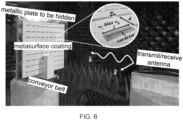
- This metasurface was designed to be placed in front of the metal plate, which was the target to be hidden from the radar.
- the target covered by the metasurface was placed on a polyester structure that connected it to a motorized conveyor belt, which enabled moving it forward and backward with a controllable speed reaching up to about 0.04m/s.
- a stepped frequency continuous wave (SFCW) radar system was implemented with a Network Analyzer, which is capable of sweeping the entire band of interest (1.2-1.7GHz) while recording the amplitude and phase of the received echoes from the target.
- SFCW stepped frequency continuous wave
- This type of radar is typically used in ultra-wideband applications since it is able to transmit carriers sequentially, while the receiver is locked on the transmitted frequency in a predefined time window.
- This architecture allows avoiding expensive high frequency samplers that would otherwise be needed for sampling extremely short pulses 37 .
- the radar's antenna was placed directly in front of the moving conveyor inside an anechoic chamber and served both for transmitting and receiving the radiation (monostatic radar scheme), linearly polarized in the direction of the dipoles (horizontal).
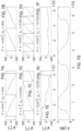
- FIGs. 7A and 7B show forward and backward motion correspondingly at constant velocity of 0.03m/s and under 1.5GHz radar illumination. It can be observed that the full span of 2 ⁇ phase was traced in the process of the movement as expected.
- FIGs. 7D, 7E and 7F show the results for the moving target while different modulation frequencies are applied to the metasurface.
- the modulation is of the same polarity as the real motion of the target, leading to their phases adding up as in Eq.5.
- the result is an overall faster changing slope, corresponding to faster motion than that of the real target.
- Fig. 7E has the modulation polarity in the opposite direction to that of the real motion, causing the target to appear slower than it is, as well making it appear to be moving towards the radar while in reality it is moving away from it.
- FIG. 7D the modulation is of the same polarity as the real motion of the target, leading to their phases adding up as in Eq.5.
- the result is an overall faster changing slope, corresponding to faster motion than that of the real target.
- Fig. 7E has the modulation polarity in the opposite direction to that of the real motion, causing the target to appear slower than it is, as well making it appear to be moving towards the radar while in reality it is moving
- This modulation frequency causes the structure to appear almost stationary to the radar, which means the MTI filter considers it as clutter, concealing the presence of the target as will be shown ahead.
- Ut is noted that the amplitude of the reflected signal is modulated as well, as shows in FIG. 7G . Since radar systems tend to rely on the phase of reflected echoes and not their intensity, this amplitude modulation does not affect the results ahead.
- FIG. 8A shows that a modulation frequency of -0.33Hz shifts the perceived velocity of the target to 0, making it appear as stationary to the radar as any of the surrounding clutter. This result is in correspondence with FIG. 7F .
- FIG. 8B shows the same results as FIG. 8A but with the additional processing of an MTI filter implemented as a two-pulse canceller, performed before the FFT processing.
- the above filter removes any static contributions of the signal, leaving only time-dependent components that change in between the samples. This can be seen more rigorously by taking the Z-transform of Eq.6.
- the maximal passband is achieved at normalized discrete frequencies of ⁇ (2 n + 1), meaning it is preferable to down-sample the phases in x k in a way that would allow the expected Doppler frequencies to pass without significant attenuation.
- This approach was undertaken to produce FIG. 8B , where the output of the FFT, corresponding to metasurface modulation frequency of -0.33Hz, is completely attenuated.
- the curves corresponding to modulation frequencies of -0.5Hz and 0Hz are also slightly attenuated by the filter due to their relatively low velocity, while the output of the FFT remains virtually unchanged for the modulation frequency of 0.5Hz. Small side-lobes remain due to the fact the phase is not completely flat, as shown in FIG. 7F .
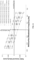
- FIGs. 8A and 8B show the output of the FFT for a select group of metasurface modulation frequencies, it is desirable to demonstrate full control over the velocity measured by the radar. To do so, the experiments mentioned earlier were repeated for 5 different real velocities of the cloaked target, as well as 25 different modulation frequencies, producing FIG. 9 .
- Two lines are drawn and marked "real velocity line” and "invisibility line". The first indicates the velocity of the target without applying any modulation to the metasurface.
- the second reveals the required modulation frequency of the metasurface in order to conceal the target (by shifting its effective Doppler signature to 0). A linear relation between the modulation frequency and the measured velocity is observed, in accordance with Eq. 5.
- Some of the data points represented by the green x's on FIG. 9 are the same ones used in FIGs. 8A and 8B , as well as in FIGs. 7A-G .
Landscapes
- Engineering & Computer Science (AREA)
- Radar, Positioning & Navigation (AREA)
- Remote Sensing (AREA)
- Physics & Mathematics (AREA)
- Computer Networks & Wireless Communication (AREA)
- General Physics & Mathematics (AREA)
- Electromagnetism (AREA)
- Radar Systems Or Details Thereof (AREA)
Claims (15)
- Système de masquage (10), comprenant :une structure (12) comportant une pluralité de résonateurs (20) ayant une fréquence de résonance contrôlable, dans lequel lesdits résonateurs (20) sont disposés de manière à garantir collectivement que la variation de ladite fréquence de résonance sur une plage prédéterminée de fréquences de résonance génère un déphasage entre une onde électromagnétique (38) incidente sur ladite structure (12) et une onde électromagnétique (42) diffusée par ladite structure (12) ; etun contrôleur (14) configuré pour contrôler ladite fréquence de résonance afin de fournir une fréquence de résonance variable dans le temps ayant une fonction temporelle qui comprend une dépendance temporelle linéaire ;caractérisé en ce que ledit contrôleur (14) est configuré pour recevoir des données de vitesse caractérisant un mouvement d'un véhicule (30) et pour sélectionner ladite fréquence de résonance variable dans le temps sur la base desdites données de vitesse.
- Système (10) selon la revendication 1, étant configuré pour une fréquence centrale de ladite onde incidente (38), dans lequel au moins un desdits résonateurs (20) a une réponse dispersive à ladite onde incidente (38), ladite réponse dispersive étant sélectionnée pour garantir que ladite plage de déphasage est efficace pour toute fréquence dans une bande de fréquence d'au moins 10 % de ladite fréquence centrale.
- Système (10) selon l'une quelconque des revendications 1 et 2, dans lequel au moins un desdits résonateurs (20) est configuré pour maintenir, dans une tolérance prédéterminée, l'égalité entre une fréquence de ladite onde diffusée (42) et une fréquence de ladite onde incidente (38).
- Système (10) selon l'une quelconque des revendications 1-3, dans lequel au moins un desdits résonateurs (20) comprend un élément électronique (24) ayant une impédance contrôlable, dans lequel ledit contrôle de ladite fréquence de résonance comprend la variation de ladite impédance.
- Système (10) selon la revendication 4, dans lequel ledit élément électronique (24) a une impédance dépendante de la tension, et dans lequel ladite variation de ladite impédance comprend la variation d'une tension appliquée audit élément électronique (24).
- Système (10) selon l'une quelconque des revendications 1-5, dans lequel au moins un desdits résonateurs (20) comprend un dipôle électrique définissant un entrefer (28), et un élément électronique (24) ayant une impédance contrôlable en correspondance dudit entrefer (28).
- Système (10) selon l'une quelconque des revendications 1-5, dans lequel au moins un desdits résonateurs (20) comprend un dipôle magnétique et un élément électronique (24) ayant une impédance contrôlable.
- Système (10) selon l'une quelconque des revendications 1-6, comprenant en outre un écran métallique (23) et une structure diélectrique (22), entre lesdits résonateurs (20) et ledit écran métallique (23), dans lequel lesdits résonateurs (20) sont montés sur ladite structure diélectrique (22).
- Système (10) selon l'une quelconque des revendications 1-8, dans lequel ledit déphasage s'étend sur une plage respective d'au moins 1,5 π.
- Véhicule (30), comprenant :un système de propulsion (34) porté par un corps de véhicule (32) ; etle système (10) selon l'une quelconque des revendications 1-7, monté sur une surface extérieure dudit corps de véhicule (32).
- Procédé de masquage ou de leurrage d'un système de détection (36) transmettant une onde électromagnétique (38) caractérisée par une fréquence centrale, le procédé comprenant :diffuser (52) l'onde (38) du système de détection par une structure (12) comportant une pluralité de résonateurs (20) ayant une fréquence de résonance contrôlable, dans lequel lesdits résonateurs (20) sont disposés de manière à garantir collectivement que la variation de ladite fréquence de résonance sur une plage prédéterminée de fréquences de résonance génère un déphasage entre l'onde (38) du système de détection et une onde électromagnétique (42) diffusée par ladite structure (12) ; etcontrôler (53) ladite fréquence de résonance pour fournir une fréquence de résonance variable dans le temps ayant une fonction temporelle ;caractérisé en ce que le procédé comprend recevoir (51) des données de vitesse caractérisant un mouvement d'un véhicule et sélectionner ladite fréquence de résonance variable dans le temps sur la base desdites données de vitesse.
- Procédé selon la revendication 11, dans lequel au moins un desdits résonateurs (20) a une réponse dispersive à l'onde (38) du système de détection, ladite réponse dispersive étant sélectionnée pour garantir que ladite plage de déphasage est efficace pour toute fréquence dans une bande de fréquence d'au moins 10 % de la fréquence centrale.
- Procédé selon l'une quelconque des revendications 11 et 12, dans lequel au moins un desdits résonateurs (20) comprend un dipôle électrique définissant un entrefer (28), et un élément électronique (24) ayant une impédance contrôlable en correspondance de l'entrefer (28).
- Procédé selon l'une quelconque des revendications 11-13, dans lequel lesdits résonateurs (20) sont montés sur une structure diélectrique (22) étant située entre un écran métallique (23) et lesdits résonateurs (20).
- Procédé selon l'une quelconque des revendications 11-14, dans lequel ledit déphasage s'étend sur une plage respective d'au moins 1,5 π.
Applications Claiming Priority (2)
| Application Number | Priority Date | Filing Date | Title |
|---|---|---|---|
| IL273995A IL273995A (en) | 2020-04-16 | 2020-04-16 | Radar invisibility and concealment using time-modulated meta-surfaces |
| PCT/IL2021/050434 WO2021210004A1 (fr) | 2020-04-16 | 2021-04-16 | Système et procédé de leurrage et de masquage d'un système de détection |
Publications (3)
| Publication Number | Publication Date |
|---|---|
| EP4136709A1 EP4136709A1 (fr) | 2023-02-22 |
| EP4136709A4 EP4136709A4 (fr) | 2023-09-13 |
| EP4136709B1 true EP4136709B1 (fr) | 2025-04-09 |
Family
ID=78084397
Family Applications (1)
| Application Number | Title | Priority Date | Filing Date |
|---|---|---|---|
| EP21788057.4A Active EP4136709B1 (fr) | 2020-04-16 | 2021-04-16 | Système et procédé de leurrage et de masquage d'un système de détection |
Country Status (4)
| Country | Link |
|---|---|
| US (1) | US12360204B2 (fr) |
| EP (1) | EP4136709B1 (fr) |
| IL (1) | IL273995A (fr) |
| WO (1) | WO2021210004A1 (fr) |
Families Citing this family (11)
| Publication number | Priority date | Publication date | Assignee | Title |
|---|---|---|---|---|
| IL273995A (en) | 2020-04-16 | 2021-10-31 | Univ Ramot | Radar invisibility and concealment using time-modulated meta-surfaces |
| US11789115B2 (en) * | 2021-03-10 | 2023-10-17 | nou Systems, Inc. | Radar cloaking apparatus and methods of use |
| KR102413884B1 (ko) * | 2021-05-26 | 2022-06-30 | 성균관대학교산학협력단 | 반사형 irs 연성 기판 |
| US12092733B2 (en) * | 2021-12-15 | 2024-09-17 | GM Global Technology Operations LLC | Radar anti-spoofing system for identifying ghost objects created by reciprocity-based sensor spoofing |
| KR102812726B1 (ko) * | 2022-06-08 | 2025-05-23 | 국방과학연구소 | 수동형 레이더 기만재밍을 위한 기만표적정보 생성 장치 및 방법 |
| IL300759A (en) * | 2023-02-15 | 2024-09-01 | Univ Ramot | System and method for angular deception of detection system |
| GB2630651A (en) * | 2023-06-02 | 2024-12-04 | Bae Systems Plc | Radar decoy |
| CN117872290B (zh) * | 2024-03-13 | 2024-06-14 | 南京理工大学 | 一种基于相位编码超表面的雷达多维特征调控方法及系统 |
| GB2641505A (en) * | 2024-06-03 | 2025-12-10 | Champion Mobile Global Ltd | A reconfigurable resonator apparatus |
| CN119247284B (zh) * | 2024-08-30 | 2025-09-19 | 西北工业大学 | 一种时域周期相位调制的电磁干扰抑制方法 |
| CN120065143B (zh) * | 2025-04-29 | 2025-07-01 | 中国人民解放军国防科技大学 | 基于分段周期调制信号的高分辨距离像模拟方法 |
Family Cites Families (18)
| Publication number | Priority date | Publication date | Assignee | Title |
|---|---|---|---|---|
| US8145119B2 (en) * | 2006-07-14 | 2012-03-27 | Kaonetics Technologies, Inc. | Method of jamming |
| US9574966B2 (en) * | 2008-02-15 | 2017-02-21 | Board Of Regents, The University Of Texas System | Passive wireless antenna sensor for strain, temperature, crack and fatigue measurement |
| WO2010120395A2 (fr) * | 2009-01-15 | 2010-10-21 | Duke University | Appareil en métamatériau large bande, procédés, systèmes, et supports pouvant être lus par un ordinateur |
| US8680945B1 (en) * | 2010-02-17 | 2014-03-25 | Lockheed Martin Corporation | Metamaterial enabled compact wideband tunable phase shifters |
| UA107833C2 (uk) * | 2012-11-29 | 2015-02-25 | Karazin Kharkiv Nat University V | Спосіб вимірювання рівня глюкози у крові |
| WO2014182398A1 (fr) | 2013-05-07 | 2014-11-13 | Board Of Regents, The University Of Texas System | Cape d'invisibilité de métasurface conformée chargée sur circuit |
| US9588255B1 (en) * | 2013-09-23 | 2017-03-07 | Iowa State University Research Foundation, Inc. | Dispersion management with metamaterials |
| US20170235162A1 (en) | 2015-07-13 | 2017-08-17 | Purdue Research Foundation | Time-varying metasurface structure |
| US20170047663A1 (en) | 2015-08-14 | 2017-02-16 | George Martin Hall | Control of rf reflectivity for radar camouflage |
| US10309909B2 (en) * | 2015-11-10 | 2019-06-04 | United Arab Emirates University | Dielectric constant detection method and device using anomalous phase dispersion |
| WO2018119153A2 (fr) * | 2016-12-21 | 2018-06-28 | Intel Corporation | Technologie de communication sans fil, appareils, et procédés |
| US11011834B2 (en) * | 2017-06-27 | 2021-05-18 | Florida State University Research Foundation, Inc. | Metamaterials, radomes including metamaterials, and methods |
| US10901082B2 (en) * | 2017-11-09 | 2021-01-26 | Fractal Antenna Systems, Inc. | Road identification system using enhanced cross-section targets |
| IL256411A (en) | 2017-12-19 | 2018-01-31 | Univ Ramot | Method and system for controlling radiation scattering |
| DE102018131054B4 (de) * | 2018-12-05 | 2020-10-08 | RF360 Europe GmbH | Mikroakustisches HF-Filter |
| CN110829033B (zh) * | 2019-10-28 | 2021-04-27 | 东南大学 | 高效率电磁波频率转换时域超表面 |
| US11428763B2 (en) * | 2020-02-28 | 2022-08-30 | Government Of The United States Of America, As Represented By The Secretary Of Commerce | Planar inverse anapole microresonator and performing inductive-detection electron paramagnetic resonance spectroscopy |
| IL273995A (en) | 2020-04-16 | 2021-10-31 | Univ Ramot | Radar invisibility and concealment using time-modulated meta-surfaces |
-
2020
- 2020-04-16 IL IL273995A patent/IL273995A/en unknown
-
2021
- 2021-04-16 WO PCT/IL2021/050434 patent/WO2021210004A1/fr not_active Ceased
- 2021-04-16 US US17/918,340 patent/US12360204B2/en active Active
- 2021-04-16 EP EP21788057.4A patent/EP4136709B1/fr active Active
Also Published As
| Publication number | Publication date |
|---|---|
| WO2021210004A1 (fr) | 2021-10-21 |
| EP4136709A4 (fr) | 2023-09-13 |
| US20230204716A1 (en) | 2023-06-29 |
| IL273995A (en) | 2021-10-31 |
| US12360204B2 (en) | 2025-07-15 |
| EP4136709A1 (fr) | 2023-02-22 |
Similar Documents
| Publication | Publication Date | Title |
|---|---|---|
| EP4136709B1 (fr) | Système et procédé de leurrage et de masquage d'un système de détection | |
| Kozlov et al. | Broadband radar invisibility with time-dependent metasurfaces | |
| Lindenfeld | Sparse frequency transmit-and-receive waveform design | |
| Ou et al. | Processing technology based on radar signal design and classification | |
| CN113534068B (zh) | 一种非线性调频信号调制干扰方法和系统 | |
| Mazumder et al. | Detection and classification of UAV using propeller Doppler profiles for counter UAV systems | |
| Kari et al. | Evolutionary developments of today’s remote sensing radar technology—Right from the telemobiloscope: A review | |
| Chen et al. | A flexible range-Doppler modulation method for pulse-Doppler radar using phase-switched screen | |
| Zhao et al. | Synchrosqueezing phase analysis on micro-Doppler parameters for small UAVs identification with multichannel radar | |
| Pető et al. | The radar cross section of small propellers on unmanned aerial vehicles | |
| Kozlov et al. | Direction of arrival deception with time-modulated scatterers | |
| Ramaccia et al. | Metasurface-based radar jammers and deceptors implemented through time-varying metasurfaces | |
| Wang et al. | Synthetic aperture radar target feature transformation method based on random code phase-switched screen | |
| Song et al. | Space-time varying plasma sheath effect on hypersonic vehicle-borne SAR imaging | |
| Harmuth | On the effect of absorbing materials on electromagnetic waves with large relative bandwidth | |
| Zhou et al. | Compensation of ionospheric phase distortion in HF hybrid sky-surface wave radar using piecewise polynomial phase modeling method | |
| Narayanan et al. | Comparison of noise and chirp waveforms for radar target detection in clutter | |
| WO2024171198A1 (fr) | Système et procédé de déception angulaire de système de détection | |
| US12355155B1 (en) | Long-range fractal-based defense system | |
| Bandyopadhyay et al. | Single Layer Polarization Insensitive Wideband Time Modulated Frequency Selective Surface for Radar Countermeasure | |
| Sun et al. | Intelligent Real-Time Self-Adaptive Electromagnetic Wave Suppressor System Functional in Broadband | |
| Kshirsagar | Carbon nanofiber for microwave absorption | |
| Li et al. | EM Scattering Center Model Guided Passive SAR Deception Using Diverse Frequency Time-modulation | |
| Anderson | Counter-OTHR 101: Low observability at HF | |
| Zhu et al. | Study on imaging quality of intrapulse intermittent modulation jamming technology based on metasurface |
Legal Events
| Date | Code | Title | Description |
|---|---|---|---|
| STAA | Information on the status of an ep patent application or granted ep patent |
Free format text: STATUS: THE INTERNATIONAL PUBLICATION HAS BEEN MADE |
|
| PUAI | Public reference made under article 153(3) epc to a published international application that has entered the european phase |
Free format text: ORIGINAL CODE: 0009012 |
|
| STAA | Information on the status of an ep patent application or granted ep patent |
Free format text: STATUS: REQUEST FOR EXAMINATION WAS MADE |
|
| 17P | Request for examination filed |
Effective date: 20221114 |
|
| AK | Designated contracting states |
Kind code of ref document: A1 Designated state(s): AL AT BE BG CH CY CZ DE DK EE ES FI FR GB GR HR HU IE IS IT LI LT LU LV MC MK MT NL NO PL PT RO RS SE SI SK SM TR |
|
| DAV | Request for validation of the european patent (deleted) | ||
| DAX | Request for extension of the european patent (deleted) | ||
| REG | Reference to a national code |
Ref country code: DE Ref legal event code: R079 Free format text: PREVIOUS MAIN CLASS: H01Q0015140000 Ipc: G01S0007020000 Ref country code: DE Ref legal event code: R079 Ref document number: 602021028989 Country of ref document: DE Free format text: PREVIOUS MAIN CLASS: H01Q0015140000 Ipc: G01S0007020000 |
|
| A4 | Supplementary search report drawn up and despatched |
Effective date: 20230811 |
|
| RIC1 | Information provided on ipc code assigned before grant |
Ipc: H01Q 15/00 20060101ALI20230807BHEP Ipc: H01Q 15/14 20060101ALI20230807BHEP Ipc: G01S 7/38 20060101ALI20230807BHEP Ipc: G01S 7/02 20060101AFI20230807BHEP |
|
| GRAP | Despatch of communication of intention to grant a patent |
Free format text: ORIGINAL CODE: EPIDOSNIGR1 |
|
| STAA | Information on the status of an ep patent application or granted ep patent |
Free format text: STATUS: GRANT OF PATENT IS INTENDED |
|
| INTG | Intention to grant announced |
Effective date: 20241112 |
|
| GRAS | Grant fee paid |
Free format text: ORIGINAL CODE: EPIDOSNIGR3 |
|
| GRAA | (expected) grant |
Free format text: ORIGINAL CODE: 0009210 |
|
| STAA | Information on the status of an ep patent application or granted ep patent |
Free format text: STATUS: THE PATENT HAS BEEN GRANTED |
|
| AK | Designated contracting states |
Kind code of ref document: B1 Designated state(s): AL AT BE BG CH CY CZ DE DK EE ES FI FR GB GR HR HU IE IS IT LI LT LU LV MC MK MT NL NO PL PT RO RS SE SI SK SM TR |
|
| REG | Reference to a national code |
Ref country code: GB Ref legal event code: FG4D |
|
| REG | Reference to a national code |
Ref country code: CH Ref legal event code: EP |
|
| REG | Reference to a national code |
Ref country code: DE Ref legal event code: R096 Ref document number: 602021028989 Country of ref document: DE |
|
| REG | Reference to a national code |
Ref country code: IE Ref legal event code: FG4D |
|
| P01 | Opt-out of the competence of the unified patent court (upc) registered |
Free format text: CASE NUMBER: APP_21867/2025 Effective date: 20250508 |
|
| PGFP | Annual fee paid to national office [announced via postgrant information from national office to epo] |
Ref country code: DE Payment date: 20250422 Year of fee payment: 5 |
|
| PGFP | Annual fee paid to national office [announced via postgrant information from national office to epo] |
Ref country code: GB Payment date: 20250527 Year of fee payment: 5 |
|
| PGFP | Annual fee paid to national office [announced via postgrant information from national office to epo] |
Ref country code: FR Payment date: 20250603 Year of fee payment: 5 |
|
| PGFP | Annual fee paid to national office [announced via postgrant information from national office to epo] |
Ref country code: AT Payment date: 20250721 Year of fee payment: 5 |
|
| REG | Reference to a national code |
Ref country code: NL Ref legal event code: MP Effective date: 20250409 |
|
| PG25 | Lapsed in a contracting state [announced via postgrant information from national office to epo] |
Ref country code: NL Free format text: LAPSE BECAUSE OF FAILURE TO SUBMIT A TRANSLATION OF THE DESCRIPTION OR TO PAY THE FEE WITHIN THE PRESCRIBED TIME-LIMIT Effective date: 20250409 |
|
| REG | Reference to a national code |
Ref country code: AT Ref legal event code: MK05 Ref document number: 1783986 Country of ref document: AT Kind code of ref document: T Effective date: 20250409 |
|
| PG25 | Lapsed in a contracting state [announced via postgrant information from national office to epo] |
Ref country code: FI Free format text: LAPSE BECAUSE OF FAILURE TO SUBMIT A TRANSLATION OF THE DESCRIPTION OR TO PAY THE FEE WITHIN THE PRESCRIBED TIME-LIMIT Effective date: 20250409 Ref country code: PT Free format text: LAPSE BECAUSE OF FAILURE TO SUBMIT A TRANSLATION OF THE DESCRIPTION OR TO PAY THE FEE WITHIN THE PRESCRIBED TIME-LIMIT Effective date: 20250811 Ref country code: ES Free format text: LAPSE BECAUSE OF FAILURE TO SUBMIT A TRANSLATION OF THE DESCRIPTION OR TO PAY THE FEE WITHIN THE PRESCRIBED TIME-LIMIT Effective date: 20250409 |
|
| REG | Reference to a national code |
Ref country code: LT Ref legal event code: MG9D |
|
| PG25 | Lapsed in a contracting state [announced via postgrant information from national office to epo] |
Ref country code: NO Free format text: LAPSE BECAUSE OF FAILURE TO SUBMIT A TRANSLATION OF THE DESCRIPTION OR TO PAY THE FEE WITHIN THE PRESCRIBED TIME-LIMIT Effective date: 20250709 Ref country code: GR Free format text: LAPSE BECAUSE OF FAILURE TO SUBMIT A TRANSLATION OF THE DESCRIPTION OR TO PAY THE FEE WITHIN THE PRESCRIBED TIME-LIMIT Effective date: 20250710 |
|
| PG25 | Lapsed in a contracting state [announced via postgrant information from national office to epo] |
Ref country code: PL Free format text: LAPSE BECAUSE OF FAILURE TO SUBMIT A TRANSLATION OF THE DESCRIPTION OR TO PAY THE FEE WITHIN THE PRESCRIBED TIME-LIMIT Effective date: 20250409 |
|
| PG25 | Lapsed in a contracting state [announced via postgrant information from national office to epo] |
Ref country code: BG Free format text: LAPSE BECAUSE OF FAILURE TO SUBMIT A TRANSLATION OF THE DESCRIPTION OR TO PAY THE FEE WITHIN THE PRESCRIBED TIME-LIMIT Effective date: 20250409 |
|
| PG25 | Lapsed in a contracting state [announced via postgrant information from national office to epo] |
Ref country code: HR Free format text: LAPSE BECAUSE OF FAILURE TO SUBMIT A TRANSLATION OF THE DESCRIPTION OR TO PAY THE FEE WITHIN THE PRESCRIBED TIME-LIMIT Effective date: 20250409 |
|
| PG25 | Lapsed in a contracting state [announced via postgrant information from national office to epo] |
Ref country code: AT Free format text: LAPSE BECAUSE OF FAILURE TO SUBMIT A TRANSLATION OF THE DESCRIPTION OR TO PAY THE FEE WITHIN THE PRESCRIBED TIME-LIMIT Effective date: 20250409 |
|
| PG25 | Lapsed in a contracting state [announced via postgrant information from national office to epo] |
Ref country code: RS Free format text: LAPSE BECAUSE OF FAILURE TO SUBMIT A TRANSLATION OF THE DESCRIPTION OR TO PAY THE FEE WITHIN THE PRESCRIBED TIME-LIMIT Effective date: 20250709 |
|
| PG25 | Lapsed in a contracting state [announced via postgrant information from national office to epo] |
Ref country code: IS Free format text: LAPSE BECAUSE OF FAILURE TO SUBMIT A TRANSLATION OF THE DESCRIPTION OR TO PAY THE FEE WITHIN THE PRESCRIBED TIME-LIMIT Effective date: 20250809 |
|
| PG25 | Lapsed in a contracting state [announced via postgrant information from national office to epo] |
Ref country code: LV Free format text: LAPSE BECAUSE OF FAILURE TO SUBMIT A TRANSLATION OF THE DESCRIPTION OR TO PAY THE FEE WITHIN THE PRESCRIBED TIME-LIMIT Effective date: 20250409 |
|
| REG | Reference to a national code |
Ref country code: CH Ref legal event code: H13 Free format text: ST27 STATUS EVENT CODE: U-0-0-H10-H13 (AS PROVIDED BY THE NATIONAL OFFICE) Effective date: 20251125 |
|
| PG25 | Lapsed in a contracting state [announced via postgrant information from national office to epo] |
Ref country code: LU Free format text: LAPSE BECAUSE OF NON-PAYMENT OF DUE FEES Effective date: 20250416 |
|
| REG | Reference to a national code |
Ref country code: BE Ref legal event code: MM Effective date: 20250430 |
|
| REG | Reference to a national code |
Ref country code: DE Ref legal event code: R097 Ref document number: 602021028989 Country of ref document: DE |
|
| PG25 | Lapsed in a contracting state [announced via postgrant information from national office to epo] |
Ref country code: DK Free format text: LAPSE BECAUSE OF FAILURE TO SUBMIT A TRANSLATION OF THE DESCRIPTION OR TO PAY THE FEE WITHIN THE PRESCRIBED TIME-LIMIT Effective date: 20250409 Ref country code: SM Free format text: LAPSE BECAUSE OF FAILURE TO SUBMIT A TRANSLATION OF THE DESCRIPTION OR TO PAY THE FEE WITHIN THE PRESCRIBED TIME-LIMIT Effective date: 20250409 |
|
| PG25 | Lapsed in a contracting state [announced via postgrant information from national office to epo] |
Ref country code: BE Free format text: LAPSE BECAUSE OF NON-PAYMENT OF DUE FEES Effective date: 20250430 |
|
| PG25 | Lapsed in a contracting state [announced via postgrant information from national office to epo] |
Ref country code: CH Free format text: LAPSE BECAUSE OF NON-PAYMENT OF DUE FEES Effective date: 20250430 |
|
| PG25 | Lapsed in a contracting state [announced via postgrant information from national office to epo] |
Ref country code: CZ Free format text: LAPSE BECAUSE OF FAILURE TO SUBMIT A TRANSLATION OF THE DESCRIPTION OR TO PAY THE FEE WITHIN THE PRESCRIBED TIME-LIMIT Effective date: 20250409 |
|
| PG25 | Lapsed in a contracting state [announced via postgrant information from national office to epo] |
Ref country code: EE Free format text: LAPSE BECAUSE OF FAILURE TO SUBMIT A TRANSLATION OF THE DESCRIPTION OR TO PAY THE FEE WITHIN THE PRESCRIBED TIME-LIMIT Effective date: 20250409 |
|
| PG25 | Lapsed in a contracting state [announced via postgrant information from national office to epo] |
Ref country code: SK Free format text: LAPSE BECAUSE OF FAILURE TO SUBMIT A TRANSLATION OF THE DESCRIPTION OR TO PAY THE FEE WITHIN THE PRESCRIBED TIME-LIMIT Effective date: 20250409 |
|
| PG25 | Lapsed in a contracting state [announced via postgrant information from national office to epo] |
Ref country code: IT Free format text: LAPSE BECAUSE OF FAILURE TO SUBMIT A TRANSLATION OF THE DESCRIPTION OR TO PAY THE FEE WITHIN THE PRESCRIBED TIME-LIMIT Effective date: 20250409 |
|
| PG25 | Lapsed in a contracting state [announced via postgrant information from national office to epo] |
Ref country code: MC Free format text: LAPSE BECAUSE OF FAILURE TO SUBMIT A TRANSLATION OF THE DESCRIPTION OR TO PAY THE FEE WITHIN THE PRESCRIBED TIME-LIMIT Effective date: 20250409 |
|
| PG25 | Lapsed in a contracting state [announced via postgrant information from national office to epo] |
Ref country code: RO Free format text: LAPSE BECAUSE OF FAILURE TO SUBMIT A TRANSLATION OF THE DESCRIPTION OR TO PAY THE FEE WITHIN THE PRESCRIBED TIME-LIMIT Effective date: 20250409 |
|
| PLBE | No opposition filed within time limit |
Free format text: ORIGINAL CODE: 0009261 |
|
| STAA | Information on the status of an ep patent application or granted ep patent |
Free format text: STATUS: NO OPPOSITION FILED WITHIN TIME LIMIT |
|
| REG | Reference to a national code |
Ref country code: CH Ref legal event code: L10 Free format text: ST27 STATUS EVENT CODE: U-0-0-L10-L00 (AS PROVIDED BY THE NATIONAL OFFICE) Effective date: 20260218 |
|
| 26N | No opposition filed |
Effective date: 20260112 |
|
| PG25 | Lapsed in a contracting state [announced via postgrant information from national office to epo] |
Ref country code: IE Free format text: LAPSE BECAUSE OF NON-PAYMENT OF DUE FEES Effective date: 20250416 |