EP4136517B1 - Navigation eines robotischen mähers entlang eines führungsdrahtes - Google Patents
Navigation eines robotischen mähers entlang eines führungsdrahtes Download PDFInfo
- Publication number
- EP4136517B1 EP4136517B1 EP20931616.5A EP20931616A EP4136517B1 EP 4136517 B1 EP4136517 B1 EP 4136517B1 EP 20931616 A EP20931616 A EP 20931616A EP 4136517 B1 EP4136517 B1 EP 4136517B1
- Authority
- EP
- European Patent Office
- Prior art keywords
- wire
- robotic mower
- signal
- distance
- guide wire
- Prior art date
- Legal status (The legal status is an assumption and is not a legal conclusion. Google has not performed a legal analysis and makes no representation as to the accuracy of the status listed.)
- Active
Links
Images


Classifications
-
- G—PHYSICS
- G05—CONTROLLING; REGULATING
- G05D—SYSTEMS FOR CONTROLLING OR REGULATING NON-ELECTRIC VARIABLES
- G05D1/00—Control of position, course, altitude or attitude of land, water, air or space vehicles, e.g. using automatic pilots
- G05D1/02—Control of position or course in two dimensions
- G05D1/021—Control of position or course in two dimensions specially adapted to land vehicles
- G05D1/0259—Control of position or course in two dimensions specially adapted to land vehicles using magnetic or electromagnetic means
- G05D1/0265—Control of position or course in two dimensions specially adapted to land vehicles using magnetic or electromagnetic means using buried wires
-
- A—HUMAN NECESSITIES
- A01—AGRICULTURE; FORESTRY; ANIMAL HUSBANDRY; HUNTING; TRAPPING; FISHING
- A01D—HARVESTING; MOWING
- A01D34/00—Mowers; Mowing apparatus of harvesters
- A01D34/006—Control or measuring arrangements
- A01D34/008—Control or measuring arrangements for automated or remotely controlled operation
-
- G—PHYSICS
- G05—CONTROLLING; REGULATING
- G05D—SYSTEMS FOR CONTROLLING OR REGULATING NON-ELECTRIC VARIABLES
- G05D1/00—Control of position, course, altitude or attitude of land, water, air or space vehicles, e.g. using automatic pilots
- G05D1/02—Control of position or course in two dimensions
- G05D1/021—Control of position or course in two dimensions specially adapted to land vehicles
- G05D1/0212—Control of position or course in two dimensions specially adapted to land vehicles with means for defining a desired trajectory
- G05D1/0225—Control of position or course in two dimensions specially adapted to land vehicles with means for defining a desired trajectory involving docking at a fixed facility, e.g. base station or loading bay
-
- G—PHYSICS
- G05—CONTROLLING; REGULATING
- G05D—SYSTEMS FOR CONTROLLING OR REGULATING NON-ELECTRIC VARIABLES
- G05D1/00—Control of position, course, altitude or attitude of land, water, air or space vehicles, e.g. using automatic pilots
- G05D1/20—Control system inputs
- G05D1/24—Arrangements for determining position or orientation
- G05D1/244—Arrangements for determining position or orientation using passive navigation aids external to the vehicle, e.g. markers, reflectors or magnetic means
-
- A—HUMAN NECESSITIES
- A01—AGRICULTURE; FORESTRY; ANIMAL HUSBANDRY; HUNTING; TRAPPING; FISHING
- A01D—HARVESTING; MOWING
- A01D2101/00—Lawn-mowers
-
- Y—GENERAL TAGGING OF NEW TECHNOLOGICAL DEVELOPMENTS; GENERAL TAGGING OF CROSS-SECTIONAL TECHNOLOGIES SPANNING OVER SEVERAL SECTIONS OF THE IPC; TECHNICAL SUBJECTS COVERED BY FORMER USPC CROSS-REFERENCE ART COLLECTIONS [XRACs] AND DIGESTS
- Y02—TECHNOLOGIES OR APPLICATIONS FOR MITIGATION OR ADAPTATION AGAINST CLIMATE CHANGE
- Y02T—CLIMATE CHANGE MITIGATION TECHNOLOGIES RELATED TO TRANSPORTATION
- Y02T10/00—Road transport of goods or passengers
- Y02T10/60—Other road transportation technologies with climate change mitigation effect
- Y02T10/70—Energy storage systems for electromobility, e.g. batteries
-
- Y—GENERAL TAGGING OF NEW TECHNOLOGICAL DEVELOPMENTS; GENERAL TAGGING OF CROSS-SECTIONAL TECHNOLOGIES SPANNING OVER SEVERAL SECTIONS OF THE IPC; TECHNICAL SUBJECTS COVERED BY FORMER USPC CROSS-REFERENCE ART COLLECTIONS [XRACs] AND DIGESTS
- Y02—TECHNOLOGIES OR APPLICATIONS FOR MITIGATION OR ADAPTATION AGAINST CLIMATE CHANGE
- Y02T—CLIMATE CHANGE MITIGATION TECHNOLOGIES RELATED TO TRANSPORTATION
- Y02T10/00—Road transport of goods or passengers
- Y02T10/60—Other road transportation technologies with climate change mitigation effect
- Y02T10/7072—Electromobility specific charging systems or methods for batteries, ultracapacitors, supercapacitors or double-layer capacitors
Definitions
- the present invention generally relates to a method for navigating a robotic mower along a signal wire, e.g., back to a charging station when a battery of the robotic mower needs to be recharged.
- Robotic mowers also called self-propelled lawnmowers, are generally known. These robotic mowers are provided with a rechargeable battery. When the remaining power in the battery is below a certain level the robotic mower is programmed to return to the charging station to recharge the battery. There are different possibilities for returning the robotic mower to the charging station.
- One possible method is that the robotic mower, upon a command to return to the charging station, continues its movement until a boundary wire is detected and then follows the boundary wire to the charging station that is provided somewhere along the boundary wire.
- Another option when returning to the charging station is to use a guide wire, which the robotic mower follows back to the charging station.
- the use of a guide wire often enables a shorter and faster way back to the charging station compared to following the boundary wire.
- the guide wire can also be beneficial to use when the robotic mower needs to navigate through a narrow passage.
- WO 2019/183907 A1 successfully addresses this by detecting, by means of at least one sensor, a signal from the guide wire and following the guide wire at a distance, wherein the distance corresponds to a given signal strength that is sensed by the at least one sensor and wherein a control unit randomly selects the signal strength each time the guide wire signal is detected.
- Another example of a solution in the field may be WO2018/010650 A1 .
- Other robotic mowers may apply ranges for signal values, and a random one of these ranges may be selected each time the robotic mower returns to the charging station. This can simplify the control of the robotic mower, but usually has the drawback of a reduction in the randomness of the actual paths of the robotic mower. Therefore, over time, tracks may still be formed at certain spots and/or in certain setups.
- the signal level usually depends on the length of the corresponding wire, and this may be different in different sites, such as smaller or larger gardens. Further, the signal level can be different depending on whether a user decides to route the wire on the surface of the ground or bury it under the surface. In practice, it can therefore be necessary for a user to adjust the settings of the robotic mower such no tracks are formed while the mower is still able to enter relatively narrow passages.
- An object of the present invention is to provide a method for navigating a robotic mower by means of a wire, and that reduces the risk of forming tracks in a simple and reliable manner.
- this object is achieved by a method for navigating a robotic mower by means of a wire, said robotic mower comprising at least one sensor, the method comprising the steps of, in the following order: detecting, by means of the at least one sensor, at least one signal from the wire, controlling the robotic mower to align with the wire, wherein the controlling comprises controlling the robotic mower to follow the wire in a first direction until detecting a straight section of the wire, and, in response to detecting the straight section of the wire, controlling the robotic mower to follow the wire in a second direction opposite the first direction, controlling the robotic mower to turn by an angle with respect to the straight section of the wire, controlling the robotic mower to increase the distance between the robotic mower and the wire by driving a displacement distance based on a random distance value along a straight line oriented at the angle the robotic mower is turned, measuring, by means of the at least one sensor, a signal level of the at least one signal from the wire, and controlling the robotic mower to follow the wire based on the measured signal level, characterized in that controlling
- the robotic mower positions itself in front of a straight-line section of the wire, so that it can precisely initially set its randomly selected distance to the wire in a predictable manner.
- the random distance value may be used twice, first for the reversing distance, and second, for the displacement distance.
- controlling the robotic mower to drive the displacement distance based on the random distance value comprises counting a number of revolutions of a rotatable component of the robotic mower, e.g., of at least one wheel of the robotic mower and/or measuring a time. This allows a high precision in setting the distance.
- controlling the robotic mower to align with the wire comprises crossing, by the robotic mower, the wire by a predetermined distance that may be referred to as crossing distance, and, optionally, determining a direction based on a polarity of the at least one signal of the wire, measured by means of the at least one sensor, and, optionally, turning the robotic mower towards the determined direction.
- crossing distance a predetermined distance that may be referred to as crossing distance
- determining a direction based on a polarity of the at least one signal of the wire, measured by means of the at least one sensor and, optionally, turning the robotic mower towards the determined direction.
- the robotic mower comprises at least two sensors, and turning the robotic mower towards the determined direction comprises rotating the robotic mower with respect to the wire until the two sensors detect the at least one signal of the wire with opposite polarity. This allows to find the right direction in a simple, yet precise and quick manner.
- the random distance value is multiplied by a first factor for calculating the reversing distance, and the random distance value is multiplied by a second factor for calculating the displacement distance.
- the first and second factors can be the same, or different from one another.
- controlling the robotic mower to turn by the angle with respect to the section of the wire comprises turning the robotic mower with respect to the section of the wire by 30 to 60 degrees, in particular by 45 degrees.
- the wire is a guide wire arranged within an area delimited by a boundary wire.
- the guide wire guides the robotic mower to a predetermined position, e.g. to the charging station and/or beyond a narrow passage.
- the method is adapted for guiding the robotic mower to a predetermined position, wherein the at least one signal from the wire is a first guiding signal and the wire is a first guiding signal source.
- the method further comprises controlling the robotic mower to follow the first guiding signal at a fixed distance from the first guiding signal source, detecting, by means of the at least one sensor, a second signal from a second signal source within a predetermined distance from the predetermined position, wherein upon detection of the second signal, controlling the robotic mower to follow the first guiding signal at a pre-configured distance from the first guiding signal source, and detecting, by means of the at least one sensor, a third signal from a third signal source and following the third signal to dock the robotic mower at the predetermined position.
- the third signal source is a portion of a boundary wire, or electrically connected with a boundary wire, wherein the boundary wire delimits an area.
- the first guiding signal source is a guide wire arranged within the area delimited by the boundary wire.
- the third signal source is a loop of the boundary wire.
- a charging station is provided at the predetermined position, and the boundary wire loop is arranged at a charging station plate of the charging station.
- the robotic mower is guided to the predetermined position more than once, wherein the fixed distance is varied each time, while the pre-configured distance is the same for each time.
- Another object is to provide a robotic mower that is adapted to navigate by means of a wire, and that reduces the risk of forming tracks in the lawn in a simple and reliable manner.
- a robotic mower comprising at least two sensors, and adapted to detect, by means of the at least one sensor, at least one signal from a wire, align with the wire, turn by an angle with respect to a section of the wire, increase the distance to the wire by driving a displacement distance based on a random distance value, measure, by means of the at least one sensor, a signal level of the at least one signal from the wire, and follow the wire based on the measured signal level, the robotic mower is further adapted to cross the wire by a predetermined crossing distance, to determine a direction based on a polarity of the at least one signal of the wire measured by means of the at least one sensor, and to turn towards the determined direction, and being further adapted to turn towards the determined direction by rotating with respect to the wire until the two sensors detect the at least one signal of the wire with opposite polarity, the robotic mower further adapted to follow the wire in a first direction until detecting a straight section of the wire, and, in response to detecting a straight section of
- the robotic mower is further adapted to count a number of revolutions of a rotatable component of the robotic mower and/or to measure a time for driving the displacement distance based on the random distance value.
- the robotic mower is further adapted to multiply the random distance value by a first factor for calculating the reversing distance, and to multiply the random distance value by a second factor for calculating the displacement distance.
- the angle to turn with respect to the section of the wire is 30 to 60 degrees, in particular 45 degrees.
- the robotic mower is adapted to perform the method of any aspect or embodiment described herein.
- a robotic mower comprising at least one sensor, and adapted to detect, by means of the at least one sensor, a first guiding signal from a first guiding signal source, follow the first guiding signal at a fixed distance from the first guiding signal source, detect, by means of the at least one sensor, a second signal from a second signal source within a predetermined distance from the predetermined position, follow the first guiding signal at a pre-configured distance from the first guiding signal source, detect, by means of the at least one sensor, a third signal from a third signal source, and follow the third signal to dock the robotic mower at the predetermined position, in particular with a charging station.
- the robotic mower is further adapted to, when navigating to the predetermined position more than once, vary the fixed distance each time, while using the same pre-configured distance each time.
- a system comprising a wire and the robotic mower according to any aspect or embodiment described herein is provided.
- the wire may be a guide wire arranged within an area delimited by a boundary wire.
- a computer program comprising computer program code
- the computer program code being adapted, when executed by one or more processers of a robotic mower, to cause the robotic mower to perform the method according to any aspect or embodiment described herein.
- a computer-readable storage medium storing computer program code, the computer program code being adapted, when executed by one or more processers, to cause a robotic mower to perform the method according to any aspect or embodiment described herein.
- a method and robotic mower for navigating the robotic mower by means of a wire are provided, that reduce the risk of forming tracks in the lawn in a simple and reliable manner.
- Fig. 1 shows a schematic overview of a system for performing the method of embodiments for navigating a robotic mower 2 by means of a guide wire 8 towards a predetermined position, such as a charging station 11.
- the robotic mower 2 or as it also may be called a self-propelling lawnmower, is battery powered and needs to be recharged at regular intervals.
- the robotic mower 2 is during operation configured to move across an area A surrounded by a boundary wire 4.
- the boundary wire 4 may be configured in many different ways, such that it delimits the area A within which the robotic mower 2 is allowed to move.
- the boundary wire 4 is preferably provided under the ground in the lawn, such that is not visible, but may also be provided on or above the ground.
- the boundary wire 4 could be an ordinary copper wire of single-core type. There are of course also other options, which are well-known by a person skilled in the art, such as multi stranded wire types. As may be seen in Fig.1 the boundary wire 4 makes a loop 4a in the charging station 11. This loop 4a will be used to guide the robotic mower 2 into charging contact with the charging station 11, which will be described further below.
- the system also comprises the charging station 11 mentioned above.
- the charging station itself 11 may be seen as the place where the charging of the robotic mower 2 takes place, and could for an example be provided with a charging plate onto which the robotic mower 2 is guided when performing docketing. A charging plate will make the docketing process more precise, since the robotic mower 2 will be at an even and predictable ground during the docketing process.
- a charging station loop 10 around the charging station 11. As shown in Fig. 1 the boundary wire loop 4a is narrower than and crosses the charging station loop 10.
- a system according to the present disclosure may also as an option comprise one or more guide wires 8.
- a guide wire 8 is a wire that the robotic mower 2 may follow when returning to the charging station 11 and/or to move along a way that is otherwise difficult to find.
- the robotic mower may also be adapted to follow the boundary wire 4 back to the charging station 11, which depending on where the robotic mower 2 starts to follow the boundary wire 4 may be quite a distance.
- By using a guide wire 8 it is possible to return the robotic mower 2 to the charging station 11 in a faster and less energy consuming way.
- the boundary wire 4, the charging station loop 10 and the one or more guide wires 8 are all connected to a signal generator which feeds each wire and loop with an Alternating Current, AC, signal, such that the robotic mower 2 may recognize which wire or loop it is detecting when it is within sensing distance.
- the robotic mower 2 may be adapted to detect magnetic fields of the different signal wires.
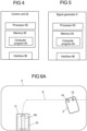
- the robotic mower 2 comprises a control unit 22, wheels 20, at least one sensor 12, 14 and a battery 18.
- the control unit 22, which will be closer described in conjunction with Fig. 4 , comprises among other things a processor 80 for controlling the movement of the robotic mower 2.
- the sensors 12, 14 can sense a magnetic field that is generated in the boundary wire 4, the charging station loop 10 and the one or several guide wires 8.
- the sensed magnetic field (signal) is decoded in the control unit 22 to determine from which loop or wire it was received.
- the robotic mower 2 further comprises charging connectors 16.
- the robotic mower 2 comprises exactly two sensors 12, 14 but in alternative embodiments the robotic mower 2 may comprise more than two, e.g., three or four sensors.
- the robotic mower 2 has a forward-rearward axis along which the robotic mower 2 moves when it drives straight ahead or straight backwards.
- the robotic mower 2 has a longitudinal extension in accordance with the forward-rearward axis.
- the two sensors 12, 14 are arranged displaced to one another in a direction orthogonal to the forward-rearward axis.
- the sensors 12, 14 are arranged in a front region of the robotic mower 2 and could be referred to as front sensors 12, 14.
- Fig. 3 shows an exemplary embodiment of the charging station 11.
- the charging station 11 comprises a charging station plate 24 at which the charging station loop 10 (which can also be referred to as far-field loop) and the boundary wire loop 4a (which may also be referred to as near-field loop) are arranged.
- the charging station 11 further comprises the signal generator 6.
- the charging station 11 comprises charging connectors 26 which are arranged so as to be contacted by the charging connectors 16 of the robotic mower 2 when docking into the charging station 11.
- the control unit 22 comprises, as mentioned above, the processor 80 and a memory 82.
- the memory 82 may comprise a computer program 84 comprising computer program code, i.e. instructions.
- the computer program code is adapted to implement method steps performed by the robotic mower 2 when the code is executed on the processor 80.
- the control unit 22 further comprises an interface 86 for communication with the sensors 12, 14, and one or more motors that operate(s) the robotic mower 2.
- the processor 80 may comprise a single Central Processing Unit (CPU), or could comprise two or more processing units.
- the processor 80 may include general purpose microprocessors, instruction set processors and/or related chips sets and/or special purpose microprocessors such as Application Specific Integrated Circuits (ASICs), Field Programmable Gate Arrays (FPGAs) or Complex Programmable Logic Devices (CPLDs).
- ASICs Application Specific Integrated Circuits
- FPGAs Field Programmable Gate Arrays
- CPLDs Complex Programmable Logic Devices
- the processor 80 may also comprise a storage for caching purposes.
- Fig. 5 depicts the signal generator 6, which also comprises a processor 60 and a memory 62.
- the memory 62 may comprise a computer program 64 comprising computer program code, i.e. instructions.
- the computer program code is adapted to implement method steps performed by the signal generator 6 when the code is executed on the processor 60.
- the signal generator 6 further comprises an interface 66 for transmitting the generated AC signals to the boundary wire 4, charging station loop 10 and guide wire or wires 8.
- processor 60 may comprise a single Central Processing Unit (CPU), or could comprise two or more processing units.
- the processor 60 may include general purpose microprocessors, instruction set processors and/or related chips sets and/or special purpose microprocessors such as Application Specific Integrated Circuits (ASICs), Field Programmable Gate Arrays (FPGAs) or Complex Programmable Logic Devices (CPLDs).
- ASICs Application Specific Integrated Circuits
- FPGAs Field Programmable Gate Arrays
- CPLDs Complex Programmable Logic Devices
- the processor 60 may also comprise a storage for caching purposes.
- a command is triggered, indicating that the robotic mower 2 shall navigate towards a predetermined position, in the present example the charging station 11.
- the command may be triggered by the signal generator 6, or by the control unit 22.
- the robotic mower 2 then starts to search for the guide wire 8.
- the robotic mower 2 drives across the area A and the sensors 12, 14 are used to listen for guide wire 8 signals.
- the guide wire 8 signals have a range, e.g. of several meters, within which the sensors 12, 14 can sense the signals.
- the robotic mower 2 is commanded to drive to the guide wire 8, e.g., simply by continuing to drive straight until the robotic mower 2 crosses the guide wire 8.
- the signal generator 6 directs current through the guide wire 8 which creates a magnetic field around the guide wire 8 having a polarity.
- the polarity of the guide wire 8 signal is opposite to the polarity at the other side of the guide wire 8.
- the robotic mower 2 crosses the guide wire 8
- one or both of the sensors 12, 14 detect a change of the polarity. By detecting this change, the robotic mower 2, more precisely, its control unit 22, is configured to determine that it crosses the guide wire 8.
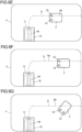
- Fig. 6A shows a situation where the robotic mower 2 detects the guide wire 8.
- a first sensor 12 of the sensors 12, 14 has crossed the guide wire 8 while the other has not, so the robotic mower 2 can deduce that it is located directly above the guide wire 8.
- the robotic mower 2 arrived at the guide wire 8 at an angle, and in the situation shown in Fig. 6A , the first sensor 12 has crossed the guide wire 8 while the other, second sensor 14 of the sensors 12, 14 has not yet crossed it.
- the robotic mower 2 determines that it is directly above the guide wire 8.
- both sensors 12, 14 would detect a switch of the polarity at the same time, so the robotic mower 2 could deduce that it is directly above the guide wire 8 in that situation.
- the robotic mower 2 in response to detecting that it is located above the guide wire 8, the robotic mower 2 is adapted to drive further (in particular, straight ahead) across the guide wire 8 for a predefined distance.
- the predefined distance may be the length of the mower or a fraction thereof, or the turning radius of the robotic mower 2 or a fraction thereof.
- both sensors 12, 14 are arranged at the same side of the guide wire 8.
- the robotic mower 2 determines the direction (along the guide wire 8) to the charging station 11. Next, the robotic mower 2 turns left or right in this determined direction of the charging station 11. While rotating relative to the guide wire 8, the robotic mower 2 analyzes the guide wire 8 signal polarity.
- the robotic mower 2 determines that the guide wire 8 is substantially aligned with the robotic mower 2, in the present example, aligned with the forward-rearward axis of the robotic mower 2.
- Fig. 6C shows the robotic mower 2 after aligning with the guide wire 8. The robotic mower 2 now faces the direction along the guide wire 8 towards the charging station 11.
- the robotic mower 2 starts to straddle the guide wire 8 with one of the sensors 12, 14 directly above the guide wire 8. In the present example, this is the right-hand side sensor 12.
- the other sensor 14 (here, as an example, the left-hand side sensor) is the one outside the guide loop, with in the figures is below the guide wire 8.
- the robotic mower 2 searches for a straight section of the wire, in particular a straight section having a predefined length, or a length being a factor of a random corridor distance Rc (described in more detail below).
- the robotic mower 2 may be adapted to search for a straight section of the guide wire 8 having a length, wherein the length is different run by run (wherein one run corresponds to navigating to the predetermined position once), in particular based on a random value.
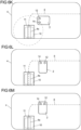
- Fig. 6E shows the robotic mower 2 after straddling along the guide wire 8 until it found a straight section 8a of the guide wire 8 by driving along the straight section 8a and determining that it is straight due to the fact that it did not have to make turns to follow the guide wire 8.
- the guide wire 8 is routed along a straight line. After detecting the straight section 8a, the robotic mower 2 stops.
- the robotic mower 2 After stopping (alternatively at a different point in time, e.g., before or while searching for a straight section of the guide wire 8, or in response to the command being triggered indicating that the robotic mower 2 shall navigate towards the predetermined position) the robotic mower 2 (more precisely, the control unit 22) determines the random corridor distance Rc to the guide wire 8 using a random number generator.
- the random corridor distance Rc may be used as a random distance value or the random distance value may be calculated based on the random corridor distance Rc.
- the random distance value is a measure for a length and is based on a random number.
- the robotic mower 2 also calculates a reversing distance based on the random distance value, e.g. by multiplying (or dividing) the random distance value by a factor, and/or using triangulation or more complex calculations.
- Fig. 6F shows that, next, the robotic mower 2 reverses and drives in the opposite direction as before along the straight section 8a of the guide wire 8 for the reversing distance.
- the reversing distance is shorter than or equal to the length of the straight section 8a.
- the robotic mower 2 turns by an angle relative to the guide wire 8.
- the robotic mower 2 turns towards the outside of the guide loop of the guide wire 8.
- the robotic mower 2 turns left.
- the robotic mower 2 turns by an angle of 45 degrees. It is not necessary to follow any signal in this regard.
- the robotic mower 2 drives straight forward by a displacement distance.
- the displacement distance is calculated by the robotic mower 2 based on the random distance value, e.g. by multiplying (or dividing) the random distance value by another factor, and/or using triangulation or more complex calculations.
- the mower is displaced to the guide wire 8 by the corridor distance Rc to the guide wire 8.
- the corridor distance Rc is the closest distance between the robotic mower 2 and the guide wire 8.
- the robotic mower 2 may be adapted to search for a straight section of the guide wire 8 having a length, wherein the length is based on the random corridor distance Rc, and/or based on the same random number used to calculate the random corridor distance Rc.
- the robotic mower 2 then stops and turns back by the angle in the opposite direction (here, 45 degrees), so as to orient in parallel with the guide wire 8. It is worth noting that for displacing the mower relative to the guide wire 8, no signal level determination is necessary. Instead, odometry is used. For determining the driving distance, in particular the displacement distance, the robotic mower 2 may control its drive motor(s) to operate at a given speed and count the time of driving. Alternatively or in addition, the robotic mower may count a number of rotations of a rotatable component of the drive mechanism, e.g., of a wheel 20, to determine the driven distance.
- the robotic mower 2 may control its drive motor(s) to operate at a given speed and count the time of driving.
- the robotic mower may count a number of rotations of a rotatable component of the drive mechanism, e.g., of a wheel 20, to determine the driven distance.
- the robotic mower 2 After stopping or after turning to be parallel to the guide wire 8, the robotic mower 2 determines the signal level of the guide wire signals 8, e.g., it determines the signal amplitude (e.g., samples the signal level). The robotic mower 2 then follows the guide wire 8 at this signal level. When the signal level changes while driving, e.g. due to a curve of the guide wire 8, the robotic mower 2 adapts its driving direction accordingly. Thus, the robotic mower 2 follows the guide wire at a constant distance that directly depends on the initial random number.
- Fig. 6J shows the robotic mower 2 after following the guide wire 8 for a certain way.
- Fig. 6K shows the robotic mower 2 after entering a range of the charging station loop 10 signals. These signals indicate to the robotic mower 2 that it is close to the charging station 11.
- the robotic mower 2 detects the charging station loop 10 signals with one or both sensors 12, 14, or with another sensor.
- the robotic mower 2 In response to detecting the charging station loop 10 signals, the robotic mower 2 turns towards the guide wire 8. In the present example, the robotic mower 2 makes a turn by 90 degrees (in this example, to the right). In other words, the robotic mower 2 turns so as to drive the shortest way to the guide wire 8.
- Fig. 6L shows the robotic mower 2 after turning towards the guide wire 8. After that, the robotic mower 2 drives straight forward towards the guide wire 8 until it detects the guide wire 8.
- Fig. 6M shows the robotic mower 2 after driving straight forward until the sensors 12, 14 detect a change in polarity of the guide wire 8 signals. The robotic mower 2 then drives further straight forward by a predefined distance, see Fig. 6N .
- the robotic mower 2 may again determine the direction towards the charging station 11 by analyzing the guide wire 8 signal polarity. The robotic mower 2 then turns towards the charging station 11 until the sensors 12, 14 detect opposite guide wire 8 signal polarities, see Fig. 6O .
- the robotic mower then starts straddling along the guide wire 8 using one sensor 12 of the two sensors 12, 14, here the sensor at the side of the robotic mower 2 inside the guide wire loop, here the right-hand-side sensor 12, see Fig. 6P .
- Fig. 6Q shows the robotic mower 2 after continuing to straddle along the guide wire 8 towards the charging station 11.
- the robotic mower 2 detects that one or both of the sensors 12, 14 has/have entered the charging station loop 10 (e.g., by a change of the measured charging station loop 10 signal polarity), see Fig. 6R .
- the robotic mower 2 docks on the charging station using the boundary wire loop 4a inside the charging station plate 24. If the left sensor 14 is outside of the boundary wire loop 4a and the right sensor 12 is inside, the robotic mower 2 turns (slightly) left. If the left sensor 14 is inside of the boundary wire loop 4a and the right sensor 12 is outside, the robotic mower 2 turns (slightly) right. Otherwise the robotic mower 2 drives straight forward until the charging connectors 16, 26 come into operative connection, e.g., make electrical contact, see Fig. 6S .
- the guide wire 8 is routed with an offset from a center line of the charging station 11 for a precise guiding using one of the sensors 12, 14. After docking, the battery 18 of the robotic mower 2 is charged.
- a more precise and reliable setting of a random distance is possible.
- the random distance value may be defined with a millimeter precision. Also, the randomness can be improved by this. As a result, the formation of tracks when the robotic mower 2 returns to the charging station many times can be strongly suppressed.
- step S100 the robotic mower 2 processes, e.g. receives, a return signal at or from the control unit 22, which commands the robotic mower 2 to return to the charging station 11.
- Step S100 may be triggered by detecting that the power in the battery 18 is lower than a predetermined limit.
- the predetermined limit is set such that the robotic mower 2 may safely return to the charging station 11 before the battery 18 is empty, even if it happens to be the longest possible way back to the charging station 11.
- the robotic mower 2 When the robotic mower 2 has processed the command to return to the charging station 11, it commences with mowing the area A until it detects the guide wire 8 by means of one or more of the robotic mower's 2 sensors 12, 14.
- the control unit 22 detects, using the at least one sensor, at least one signal from the wire, e.g., guide wire 8, in particular, a first guiding signal, wherein the guide wire 8 is a first guiding signal source. Thus, the control unit 22 determines that the wire or guide wire 8 is close.
- the control unit 22 controls the robotic mower 2 to align itself with the wire, e.g., guide wire 8. For example, by aligning with the guide wire 8, the robotic mower 2 drives over the guide wire 8 and turns such that a longitudinal extension of the robotic mower 2 is oriented on the same axis as the section of the guide wire 8 below the robotic mower 2.
- aligning with the wire comprises the step S200 of crossing, by the robotic mower 2, the wire 8 by a predetermined crossing distance.
- aligning may comprise the step S201 of determining a direction based on a polarity of the at least one signal of the guide wire 8, measured by means of the at least one sensor 12, 14.
- aligning may comprise the step S202 of turning the robotic mower towards the determined direction.
- turning the robotic mower 2 towards the determined direction may comprise rotating the robotic mower 2 with respect to the guide wire 8 until the two sensors 12, 14 detect the at least one signal of the guide wire 8 with opposite polarity.
- the step S102 of aligning the robotic mower 2 with the guide wire 8 may comprise the step S203 of controlling the robotic mower 2 to follow the guide wire 8 in a first direction until detecting a straight-line section 8a of the wire 8 (e.g., having a predetermined length), and, in response to detecting the straight section 8a of the guide wire 8, may comprise the step S204 of controlling the robotic mower 2 to follow the guide wire 8 in a second direction opposite the first direction.
- the first direction is the direction along the guide wire 8 towards the charging station 11
- the second direction is the direction along the guide wire 8 away from the charging station.
- step S103 comprises controlling the robotic mower 2 to turn by an angle with respect to the straight section 8a of the guide wire 8, e.g. by 45 degrees.
- control unit 22 controls the robotic mower 2 to increase the distance between itself and the guide wire 8 by driving a displacement distance based on a random distance value, and along a straight line oriented at the angle the robotic mower turned in step S103.
- step S105 comprising measuring, by means of the at least one sensor, a signal level, e.g. an amplitude, of the at least one signal from the guide wire 8.
- a signal level e.g. an amplitude
- step S106 the control unit 22 controls the robotic mower 2 to follow the guide wire 8 in a fixed distance that is constant along the guide wire 8, e.g., based on the measured signal level, what is a simple and effective way to maintain the distance to the guide wire that has been randomly set before.
- the steps S100 through S106 are repeated each time when the robotic mower 2 returns to the charging station 11, or, more generally, when driving to a predetermined position.
- a method for guiding a robotic mower 2 to a predetermined position e.g., the charging station 11, is provided.
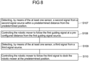
- the method proceeds from step S106 described above to step S107 as shown in Fig. 8 .
- steps S102 through S105 are omitted, alternatively these steps are performed as well.
- the robotic mower 2 detects, by means of the at least one sensor 12, 14, a second signal from a second signal source 10 within a predetermined distance from the predetermined position.
- the second signal source is, e.g., the charging station loop 10.
- step S108 the robotic mower 2 is controlled to follow the first guiding signal at a pre-configured distance from the first guiding signal source, in particular the guide wire 8.
- step S109 wherein the robotic mower 2 detects, by means of the at least one sensor 12, 14, a third signal from a third signal source, e.g. the loop 4a of the boundary wire 4.
- a third signal source e.g. the loop 4a of the boundary wire 4.
- the robotic mower 2 is controlled to follow the third signal to dock the robotic mower at the charging station 11 at the predetermined position, e.g., by electrically contacting charging connectors of the charging station 11. It is worth noting that the robotic mower 2 may be guided to the predetermined position more than once. Specifically, the robotic mower 2 may be adapted such that the fixed distance is varied each time the robotic mower 2 is guided to the predetermined position, while the pre-configured distance each time is the same.
Landscapes
- Engineering & Computer Science (AREA)
- Physics & Mathematics (AREA)
- Aviation & Aerospace Engineering (AREA)
- Radar, Positioning & Navigation (AREA)
- Remote Sensing (AREA)
- General Physics & Mathematics (AREA)
- Automation & Control Theory (AREA)
- Life Sciences & Earth Sciences (AREA)
- Environmental Sciences (AREA)
- Electromagnetism (AREA)
- Harvester Elements (AREA)
- Control Of Position, Course, Altitude, Or Attitude Of Moving Bodies (AREA)
Claims (13)
- Verfahren zum Navigieren eines Robotermähers (2) mittels eines Drahtes (8), wobei der Robotermäher (2) mindestens einen Sensor (12; 14) umfasst, wobei das Verfahren die folgenden Schritte in der folgenden Reihenfolge umfasst:- Erkennen (S101), mittels des mindestens einen Sensors (12, 14), mindestens eines Signals vom Draht (8),- Steuern (S102) des Robotermähers (2), um sich an dem Draht (8) auszurichten, wobei das Steuern (S102) Steuern (S203) des Robotermähers (2) umfasst, um dem Draht (8) in einer ersten Richtung zu folgen, bis ein gerader Abschnitt (8a) des Drahtes (8) erkannt wird, und als Reaktion auf Erkennen des geraden Abschnitts (8a) des Drahtes (8) Steuern (S204) des Robotermähers (2), um dem Draht (8) in einer zweiten Richtung zu folgen, die der ersten Richtung entgegengesetzt ist,- Steuern (S103) des Robotermähers (2), um eine Drehung um einen Winkel in Bezug auf den geraden Abschnitt (8a) des Drahtes (8) auszuführen,- Steuern (S104) des Robotermähers (2), um den Abstand zwischen dem Robotermäher (2) und dem Draht (8) zu vergrößern, indem ein auf einem zufälligen Abstandswert basierender Verschiebungsabstand entlang einer geraden Linie gefahren wird, die in dem Winkel ausgerichtet ist, um dem der Robotermäher (2) gedreht wird,- Messen (S105), mittels des mindestens einen Sensors (12, 14), eines Signalpegels des mindestens einen Signals von dem Draht (8), und- Steuern (S106) des Robotermähers (2), um dem Draht (8) basierend auf dem gemessenen Signalpegel zu folgen,
wobei Steuern (S204) des Robotermähers (2), um dem Draht (8) in der zweiten Richtung zu folgen, Fahren eines auf dem zufälligen Abstandswert basierenden Rückfahrabstands umfasst. - Verfahren nach Anspruch 1, wobei Steuern (S104) des Robotermähers (2), um basierend auf dem zufälligen Abstandswert den Verschiebungsabstand zu fahren, Zählen einer Anzahl von Umdrehungen einer rotierbaren Komponente des Robotermähers (2) und/oder Messen einer Zeit umfasst.
- Verfahren nach Anspruch 1 oder 2, wobei Steuern (S102) des Robotermähers (2), um sich an dem Draht (8) auszurichten, Überqueren (S200) des Drahtes (8) durch den Robotermäher (2) um einen vorbestimmten Überquerungsabstand, Bestimmen (S201) einer Richtung basierend auf einer Polarität des mindestens einen Signals des Drahtes (8), gemessen mittels des mindestens einen Sensors (12, 14), und Drehen (S202) des Robotermähers (2) in die bestimmte Richtung umfasst.
- Verfahren nach Anspruch 3, wobei der Robotermäher (2) mindestens zwei Sensoren (12, 14) umfasst und Drehen (S202) des Robotermähers (2) in die bestimmte Richtung Rotieren des Robotermähers (2) in Bezug auf den Draht (8) umfasst, bis die zwei Sensoren (12, 14) das mindestens eine Signal des Drahtes (8) mit entgegengesetzter Polarität erkennen.
- Verfahren nach Anspruch 1, wobei der zufällige Abstandswert zur Berechnung des Rückfahrabstands mit einem ersten Faktor multipliziert wird und der zufällige Abstandswert zur Berechnung des Verschiebungsabstands mit einem zweiten Faktor multipliziert wird.
- Verfahren nach einem der Ansprüche 1 bis 5, das weiter dazu angepasst ist, den Robotermäher (2) zu einer vorgegebenen Position zu führen, wobei das mindestens eine Signal vom Draht (8) ein erstes Führungssignal ist und der Draht (8) eine erste Führungssignalquelle ist, wobei das Verfahren weiter Folgendes umfasst:- Steuern (S106) des Robotermähers (2), um dem ersten Führungssignal (8) in einem festen Abstand zur ersten Führungssignalquelle (8) zu folgen,- Erkennen (S107), mittels des mindestens einen Sensors (12, 14), eines zweiten Signals von einer zweiten Signalquelle (10) innerhalb eines vorgegebenen Abstands von der vorgegebenen Position, wobei bei Erkennen des zweiten Signals- Steuern (S108) des Robotermähers (2), um dem ersten Führungssignal (8) in einem vorkonfigurierten Abstand von der ersten Führungssignalquelle (8) zu folgen,- Erkennen (S109), mittels des mindestens einen Sensors (12, 14), eines dritten Signals von einer dritten Signalquelle (4a), und- Steuern (S110) des Robotermähers (2), um dem dritten Signal zu folgen, um den Robotermäher (2) an der vorbestimmten Position anzudocken.
- Verfahren nach Anspruch 6, wobei die dritte Signalquelle (4a) ein Abschnitt eines Begrenzungsdrahtes (4) ist, der einen Bereich (A) abgrenzt, oder mit diesem elektrisch verbunden ist, wobei die erste Führungssignalquelle (8) ein Führungsdraht (8) ist, der innerhalb des durch den Begrenzungsdraht (4) abgegrenzten Bereichs (A) angeordnet ist.
- Verfahren nach Anspruch 7, wobei an der vorgegebenen Position eine Ladestation (11) bereitgestellt ist und die Begrenzungsdrahtschleife (4a) an einer Ladestationsplatte (24) der Ladestation (11) angeordnet wird, wobei der Robotermäher (2) mehr als einmal zu der vorgegebenen Position geführt wird, wobei der feste Abstand jedes Mal variiert wird, während der vorkonfigurierte Abstand jedes Mal derselbe ist.
- Robotermäher (2), der mindestens zwei Sensoren (12, 14) umfasst und für Folgendes angepasst ist:- Erkennen, mittels des mindestens einen Sensors (12, 14), mindestens eines Signals von einem Draht (8),- Ausrichten an dem Draht (8),- Drehen um einen Winkel in Bezug auf einen Abschnitt (8a) des Drahtes (8),- Vergrößern des Abstands zum Draht (8) durch Fahren eines auf einem zufälligen Abstandswert basierenden Verschiebungsabstands,- Messen, mittels des mindestens einen Sensors (12, 14), eines Signalpegels des mindestens einen Signals vom Draht (8) und- Folgen dem Draht (8) basierend auf dem gemessenen Signalpegel,wobei der Robotermäher (2) weiter dazu angepasst ist, den Draht (8) um einen vorgegebenen Überquerungsabstand zu überqueren, um eine Richtung basierend auf einer Polarität des mindestens einen Signals des Drahtes (8) zu bestimmen, das mittels des mindestens einen Sensors (12, 14) gemessen wird, und sich in die bestimmte Richtung zu drehen, und weiter dazu angepasst ist, sich durch Rotieren in Bezug auf den Draht (8) in die bestimmte Richtung zu drehen, bis die zwei Sensoren (12, 14) das mindestens eine Signal des Drahtes (8) mit entgegengesetzter Polarität erkennen, wobei der Robotermäher (2) weiter dazu angepasst ist, dem Draht (8) in einer ersten Richtung zu folgen, bis er einen geraden Abschnitt (8a) des Drahtes (8) erkennt, und als Reaktion auf Erkennen eines geraden Abschnitts (8a) des Drahtes (8) dem Draht (8) in einer zweiten Richtung zu folgen, die der ersten Richtung entgegengesetzt ist,wobei der Robotermäher (2) weiter dazu angepasst ist, dem Draht (8) in der zweiten Richtung zu folgen, indem er basierend auf dem zufälligen Abstandswert einen Rückfahrabstand fährt.
- Robotermäher (2) nach Anspruch 9, der weiter dazu angepasst ist, eine Anzahl von Umdrehungen einer rotierbaren Komponente des Robotermähers (2) zu zählen und/oder eine Zeit zum Fahren des auf dem zufälligen Abstandswert basierenden Verschiebungsabstands zu messen.
- Robotermäher (2) nach Anspruch 10, der weiter dazu angepasst ist, den zufälligen Abstandswert zum Berechnen des Rückfahrabstands mit einem ersten Faktor zu multiplizieren und den zufälligen Abstandswert zum Berechnen des Verschiebungsabstands mit einem zweiten Faktor zu multiplizieren.
- Computerprogramm, das Computerprogrammcode umfasst, wobei der Computerprogrammcode dazu angepasst ist, wenn er von einem oder mehreren Prozessoren (80) eines Robotermähers (2) ausgeführt wird, zu bewirken, dass der Robotermäher (2) das Verfahren nach einem der Ansprüche 1 bis 8 durchführt.
- Computerlesbares Speichermedium, das Computerprogrammcode speichert, wobei der Computerprogrammcode dazu angepasst ist, wenn er von einem oder mehreren Prozessoren (80) eines Robotermähers (2) ausgeführt wird, zu bewirken, dass der Robotermäher (2) das Verfahren nach einem der Ansprüche 1 bis 8 durchführt.
Applications Claiming Priority (1)
| Application Number | Priority Date | Filing Date | Title |
|---|---|---|---|
| PCT/CN2020/085103 WO2021208010A1 (en) | 2020-04-16 | 2020-04-16 | Navigating a robotic mower along a guide wire |
Publications (4)
| Publication Number | Publication Date |
|---|---|
| EP4136517A1 EP4136517A1 (de) | 2023-02-22 |
| EP4136517A4 EP4136517A4 (de) | 2023-08-16 |
| EP4136517B1 true EP4136517B1 (de) | 2025-03-19 |
| EP4136517C0 EP4136517C0 (de) | 2025-03-19 |
Family
ID=78084782
Family Applications (1)
| Application Number | Title | Priority Date | Filing Date |
|---|---|---|---|
| EP20931616.5A Active EP4136517B1 (de) | 2020-04-16 | 2020-04-16 | Navigation eines robotischen mähers entlang eines führungsdrahtes |
Country Status (4)
| Country | Link |
|---|---|
| US (1) | US12585279B2 (de) |
| EP (1) | EP4136517B1 (de) |
| CN (1) | CN115605818B (de) |
| WO (1) | WO2021208010A1 (de) |
Families Citing this family (7)
| Publication number | Priority date | Publication date | Assignee | Title |
|---|---|---|---|---|
| EP4136517B1 (de) | 2020-04-16 | 2025-03-19 | Globe (Jiangsu) Co., Ltd. | Navigation eines robotischen mähers entlang eines führungsdrahtes |
| KR102423497B1 (ko) * | 2020-07-02 | 2022-07-21 | 엘지전자 주식회사 | 로봇 청소기의 제어 방법 |
| EP4228391A4 (de) * | 2020-10-19 | 2023-12-27 | Globe (Jiangsu) Co., Ltd. | Navigieren eines robotischen mähers mit koppelnavigationssystem |
| EP4268034A4 (de) | 2020-12-25 | 2024-06-05 | Globe (Jiangsu) Co., Ltd. | Navigation eines robotischen mähers entlang eines drahts |
| DE102021131214A1 (de) | 2021-11-29 | 2023-06-01 | Honda Motor Co., Ltd. | Fahrtroutensteuerung eines autonomen Arbeitsfahrzeugs |
| WO2024183269A1 (zh) * | 2023-03-03 | 2024-09-12 | 深圳乐动机器人股份有限公司 | 一种机器人控制方法、装置及机器人 |
| WO2024212441A1 (zh) * | 2023-04-13 | 2024-10-17 | 深圳乐动机器人股份有限公司 | 区域划分方法、装置及计算机可读存储介质 |
Family Cites Families (17)
| Publication number | Priority date | Publication date | Assignee | Title |
|---|---|---|---|---|
| AU2010348406B2 (en) * | 2010-03-17 | 2014-10-23 | Husqvarna Ab | Method and system for guiding a robotic garden tool to a predetermined position |
| US8392044B2 (en) * | 2010-07-28 | 2013-03-05 | Deere & Company | Robotic mower boundary sensing system |
| US8433468B2 (en) * | 2010-07-28 | 2013-04-30 | Deere & Company | Robotic mower home finding system |
| US8352113B2 (en) * | 2010-07-28 | 2013-01-08 | Deere & Company | Robotic mower boundary coverage system |
| CN103507067B (zh) * | 2012-06-15 | 2016-01-20 | 华硕电脑股份有限公司 | 机器人装置以及导引机器人返回基站的方法 |
| CN103576678B (zh) * | 2012-07-20 | 2016-12-21 | 苏州宝时得电动工具有限公司 | 自动返回系统及控制自动行走设备返回停靠站的方法 |
| CN103891464B (zh) * | 2012-12-28 | 2016-08-17 | 苏州宝时得电动工具有限公司 | 自动割草系统 |
| WO2015115949A1 (en) * | 2014-01-30 | 2015-08-06 | Husqvarna Ab | Robotic working tool system with a boundary wire |
| WO2017192981A1 (en) * | 2016-05-06 | 2017-11-09 | Mtd Products Inc | Autonomous mower navigation system and method |
| CN107608341A (zh) * | 2016-07-11 | 2018-01-19 | 苏州宝时得电动工具有限公司 | 自动工作系统及自移动园艺设备的回归控制方法 |
| SE540605C2 (en) * | 2017-03-02 | 2018-10-02 | Husqvarna Ab | Improved reduction of wheel tracks for robotic lawnmower |
| CN107390685B (zh) * | 2017-07-14 | 2020-10-16 | 深圳市优必选科技有限公司 | 一种机器人的回充控制方法、机器人及机器人系统 |
| SE541895C2 (en) * | 2018-01-31 | 2020-01-02 | Husqvarna Ab | System and method for navigating a robotic lawnmower into a docking position |
| ES2895519T3 (es) * | 2018-02-07 | 2022-02-21 | Globe Jiangsu Co Ltd | Sistema y método de acoplamiento de un robot cortacésped |
| US11474524B2 (en) | 2018-03-30 | 2022-10-18 | Globe (jiangsu) Co., Ltd. | Robotic mower and method for controlling a robotic mower |
| CN108594811A (zh) * | 2018-04-12 | 2018-09-28 | 南京苏美达智能技术有限公司 | 割草机器人离开基站的方法 |
| EP4136517B1 (de) | 2020-04-16 | 2025-03-19 | Globe (Jiangsu) Co., Ltd. | Navigation eines robotischen mähers entlang eines führungsdrahtes |
-
2020
- 2020-04-16 EP EP20931616.5A patent/EP4136517B1/de active Active
- 2020-04-16 WO PCT/CN2020/085103 patent/WO2021208010A1/en not_active Ceased
- 2020-04-16 CN CN202080099747.0A patent/CN115605818B/zh active Active
-
2022
- 2022-10-12 US US17/964,055 patent/US12585279B2/en active Active
Also Published As
| Publication number | Publication date |
|---|---|
| US12585279B2 (en) | 2026-03-24 |
| CN115605818A (zh) | 2023-01-13 |
| EP4136517A4 (de) | 2023-08-16 |
| US20230030855A1 (en) | 2023-02-02 |
| EP4136517A1 (de) | 2023-02-22 |
| EP4136517C0 (de) | 2025-03-19 |
| CN115605818B (zh) | 2025-10-31 |
| WO2021208010A1 (en) | 2021-10-21 |
Similar Documents
| Publication | Publication Date | Title |
|---|---|---|
| EP4136517B1 (de) | Navigation eines robotischen mähers entlang eines führungsdrahtes | |
| EP3599812B1 (de) | System und verfahren zum andocken eines robotermähers | |
| US12535820B2 (en) | Navigating a robotic mower with dead reckoning | |
| US20230094888A1 (en) | Navigating a robotic mower along a guide wire | |
| EP3599813B1 (de) | Robotermäher und verfahren zur steuerung eines robotermähers | |
| JP7231761B2 (ja) | ベースへ戻すためのロボットの制御方法 | |
| EP3746857B1 (de) | System und verfahren zum navigieren eines robotischen rasenmähers in eine andockposition | |
| EP2853975B1 (de) | Mähroboternavigationssystem | |
| CN110392523B (zh) | 用于机器人割草机的改进的轮轨减少 | |
| US12464978B2 (en) | Navigating a robotic mower along a wire | |
| US20250076885A1 (en) | Autonomous movement system | |
| JPH03286314A (ja) | 無人走行装置における無人走行車の走行誤差検出装置 |
Legal Events
| Date | Code | Title | Description |
|---|---|---|---|
| STAA | Information on the status of an ep patent application or granted ep patent |
Free format text: STATUS: THE INTERNATIONAL PUBLICATION HAS BEEN MADE |
|
| PUAI | Public reference made under article 153(3) epc to a published international application that has entered the european phase |
Free format text: ORIGINAL CODE: 0009012 |
|
| STAA | Information on the status of an ep patent application or granted ep patent |
Free format text: STATUS: REQUEST FOR EXAMINATION WAS MADE |
|
| 17P | Request for examination filed |
Effective date: 20221028 |
|
| AK | Designated contracting states |
Kind code of ref document: A1 Designated state(s): AL AT BE BG CH CY CZ DE DK EE ES FI FR GB GR HR HU IE IS IT LI LT LU LV MC MK MT NL NO PL PT RO RS SE SI SK SM TR |
|
| TPAC | Observations filed by third parties |
Free format text: ORIGINAL CODE: EPIDOSNTIPA |
|
| RIC1 | Information provided on ipc code assigned before grant |
Ipc: G05D 1/02 20200101AFI20230404BHEP |
|
| DAV | Request for validation of the european patent (deleted) | ||
| DAX | Request for extension of the european patent (deleted) | ||
| A4 | Supplementary search report drawn up and despatched |
Effective date: 20230718 |
|
| RIC1 | Information provided on ipc code assigned before grant |
Ipc: G05D 1/02 20200101AFI20230712BHEP |
|
| REG | Reference to a national code |
Ref legal event code: R079 Free format text: PREVIOUS MAIN CLASS: G05D0001020000 Ipc: G05D0001000000 Ref country code: DE Ref legal event code: R079 Ref document number: 602020048156 Country of ref document: DE Free format text: PREVIOUS MAIN CLASS: G05D0001020000 Ipc: G05D0001000000 |
|
| RIC1 | Information provided on ipc code assigned before grant |
Ipc: G05D 1/00 20060101AFI20241010BHEP |
|
| GRAP | Despatch of communication of intention to grant a patent |
Free format text: ORIGINAL CODE: EPIDOSNIGR1 |
|
| STAA | Information on the status of an ep patent application or granted ep patent |
Free format text: STATUS: GRANT OF PATENT IS INTENDED |
|
| INTG | Intention to grant announced |
Effective date: 20241118 |
|
| GRAS | Grant fee paid |
Free format text: ORIGINAL CODE: EPIDOSNIGR3 |
|
| GRAA | (expected) grant |
Free format text: ORIGINAL CODE: 0009210 |
|
| STAA | Information on the status of an ep patent application or granted ep patent |
Free format text: STATUS: THE PATENT HAS BEEN GRANTED |
|
| AK | Designated contracting states |
Kind code of ref document: B1 Designated state(s): AL AT BE BG CH CY CZ DE DK EE ES FI FR GB GR HR HU IE IS IT LI LT LU LV MC MK MT NL NO PL PT RO RS SE SI SK SM TR |
|
| REG | Reference to a national code |
Ref country code: GB Ref legal event code: FG4D |
|
| REG | Reference to a national code |
Ref country code: CH Ref legal event code: EP |
|
| REG | Reference to a national code |
Ref country code: IE Ref legal event code: FG4D |
|
| REG | Reference to a national code |
Ref country code: DE Ref legal event code: R096 Ref document number: 602020048156 Country of ref document: DE |
|
| U01 | Request for unitary effect filed |
Effective date: 20250319 |
|
| U07 | Unitary effect registered |
Designated state(s): AT BE BG DE DK EE FI FR IT LT LU LV MT NL PT RO SE SI Effective date: 20250326 |
|
| U20 | Renewal fee for the european patent with unitary effect paid |
Year of fee payment: 6 Effective date: 20250417 |
|
| PG25 | Lapsed in a contracting state [announced via postgrant information from national office to epo] |
Ref country code: RS Free format text: LAPSE BECAUSE OF FAILURE TO SUBMIT A TRANSLATION OF THE DESCRIPTION OR TO PAY THE FEE WITHIN THE PRESCRIBED TIME-LIMIT Effective date: 20250619 |
|
| PG25 | Lapsed in a contracting state [announced via postgrant information from national office to epo] |
Ref country code: NO Free format text: LAPSE BECAUSE OF FAILURE TO SUBMIT A TRANSLATION OF THE DESCRIPTION OR TO PAY THE FEE WITHIN THE PRESCRIBED TIME-LIMIT Effective date: 20250619 |
|
| PG25 | Lapsed in a contracting state [announced via postgrant information from national office to epo] |
Ref country code: HR Free format text: LAPSE BECAUSE OF FAILURE TO SUBMIT A TRANSLATION OF THE DESCRIPTION OR TO PAY THE FEE WITHIN THE PRESCRIBED TIME-LIMIT Effective date: 20250319 |
|
| PG25 | Lapsed in a contracting state [announced via postgrant information from national office to epo] |
Ref country code: GR Free format text: LAPSE BECAUSE OF FAILURE TO SUBMIT A TRANSLATION OF THE DESCRIPTION OR TO PAY THE FEE WITHIN THE PRESCRIBED TIME-LIMIT Effective date: 20250620 |
|
| PG25 | Lapsed in a contracting state [announced via postgrant information from national office to epo] |
Ref country code: SM Free format text: LAPSE BECAUSE OF FAILURE TO SUBMIT A TRANSLATION OF THE DESCRIPTION OR TO PAY THE FEE WITHIN THE PRESCRIBED TIME-LIMIT Effective date: 20250319 |
|
| PG25 | Lapsed in a contracting state [announced via postgrant information from national office to epo] |
Ref country code: ES Free format text: LAPSE BECAUSE OF FAILURE TO SUBMIT A TRANSLATION OF THE DESCRIPTION OR TO PAY THE FEE WITHIN THE PRESCRIBED TIME-LIMIT Effective date: 20250319 |
|
| PG25 | Lapsed in a contracting state [announced via postgrant information from national office to epo] |
Ref country code: PL Free format text: LAPSE BECAUSE OF FAILURE TO SUBMIT A TRANSLATION OF THE DESCRIPTION OR TO PAY THE FEE WITHIN THE PRESCRIBED TIME-LIMIT Effective date: 20250319 |
|
| PG25 | Lapsed in a contracting state [announced via postgrant information from national office to epo] |
Ref country code: CZ Free format text: LAPSE BECAUSE OF FAILURE TO SUBMIT A TRANSLATION OF THE DESCRIPTION OR TO PAY THE FEE WITHIN THE PRESCRIBED TIME-LIMIT Effective date: 20250319 |
|
| PG25 | Lapsed in a contracting state [announced via postgrant information from national office to epo] |
Ref country code: SK Free format text: LAPSE BECAUSE OF FAILURE TO SUBMIT A TRANSLATION OF THE DESCRIPTION OR TO PAY THE FEE WITHIN THE PRESCRIBED TIME-LIMIT Effective date: 20250319 |
|
| PG25 | Lapsed in a contracting state [announced via postgrant information from national office to epo] |
Ref country code: IS Free format text: LAPSE BECAUSE OF FAILURE TO SUBMIT A TRANSLATION OF THE DESCRIPTION OR TO PAY THE FEE WITHIN THE PRESCRIBED TIME-LIMIT Effective date: 20250719 |
|
| REG | Reference to a national code |
Ref country code: CH Ref legal event code: H13 Free format text: ST27 STATUS EVENT CODE: U-0-0-H10-H13 (AS PROVIDED BY THE NATIONAL OFFICE) Effective date: 20251125 |
|
| PG25 | Lapsed in a contracting state [announced via postgrant information from national office to epo] |
Ref country code: MC Free format text: LAPSE BECAUSE OF FAILURE TO SUBMIT A TRANSLATION OF THE DESCRIPTION OR TO PAY THE FEE WITHIN THE PRESCRIBED TIME-LIMIT Effective date: 20250319 |
|
| PG25 | Lapsed in a contracting state [announced via postgrant information from national office to epo] |
Ref country code: CH Free format text: LAPSE BECAUSE OF NON-PAYMENT OF DUE FEES Effective date: 20250430 |
|
| PLBE | No opposition filed within time limit |
Free format text: ORIGINAL CODE: 0009261 |
|
| STAA | Information on the status of an ep patent application or granted ep patent |
Free format text: STATUS: NO OPPOSITION FILED WITHIN TIME LIMIT |
|
| REG | Reference to a national code |
Ref country code: CH Ref legal event code: L10 Free format text: ST27 STATUS EVENT CODE: U-0-0-L10-L00 (AS PROVIDED BY THE NATIONAL OFFICE) Effective date: 20260128 |
|
| 26N | No opposition filed |
Effective date: 20251222 |
|
| GBPC | Gb: european patent ceased through non-payment of renewal fee |
Effective date: 20250619 |
|
| PG25 | Lapsed in a contracting state [announced via postgrant information from national office to epo] |
Ref country code: GB Free format text: LAPSE BECAUSE OF NON-PAYMENT OF DUE FEES Effective date: 20250619 |
|
| PG25 | Lapsed in a contracting state [announced via postgrant information from national office to epo] |
Ref country code: IE Free format text: LAPSE BECAUSE OF NON-PAYMENT OF DUE FEES Effective date: 20250416 |