EP4136346B1 - Anpassbare anordnung einer turmplattform - Google Patents
Anpassbare anordnung einer turmplattform Download PDFInfo
- Publication number
- EP4136346B1 EP4136346B1 EP21722208.2A EP21722208A EP4136346B1 EP 4136346 B1 EP4136346 B1 EP 4136346B1 EP 21722208 A EP21722208 A EP 21722208A EP 4136346 B1 EP4136346 B1 EP 4136346B1
- Authority
- EP
- European Patent Office
- Prior art keywords
- tower
- platform
- adaptable
- diameter
- interior
- Prior art date
- Legal status (The legal status is an assumption and is not a legal conclusion. Google has not performed a legal analysis and makes no representation as to the accuracy of the status listed.)
- Active
Links
Images


Classifications
-
- F—MECHANICAL ENGINEERING; LIGHTING; HEATING; WEAPONS; BLASTING
- F03—MACHINES OR ENGINES FOR LIQUIDS; WIND, SPRING, OR WEIGHT MOTORS; PRODUCING MECHANICAL POWER OR A REACTIVE PROPULSIVE THRUST, NOT OTHERWISE PROVIDED FOR
- F03D—WIND MOTORS
- F03D13/00—Assembly, mounting or commissioning of wind motors; Arrangements specially adapted for transporting wind motor components
- F03D13/20—Arrangements for mounting or supporting wind motors; Masts or towers for wind motors
-
- F—MECHANICAL ENGINEERING; LIGHTING; HEATING; WEAPONS; BLASTING
- F03—MACHINES OR ENGINES FOR LIQUIDS; WIND, SPRING, OR WEIGHT MOTORS; PRODUCING MECHANICAL POWER OR A REACTIVE PROPULSIVE THRUST, NOT OTHERWISE PROVIDED FOR
- F03D—WIND MOTORS
- F03D80/00—Details, components or accessories not provided for in groups F03D1/00 - F03D17/00
- F03D80/80—Arrangement of components within nacelles or towers
- F03D80/88—Arrangement of components within nacelles or towers of mechanical components
-
- F—MECHANICAL ENGINEERING; LIGHTING; HEATING; WEAPONS; BLASTING
- F05—INDEXING SCHEMES RELATING TO ENGINES OR PUMPS IN VARIOUS SUBCLASSES OF CLASSES F01-F04
- F05B—INDEXING SCHEME RELATING TO WIND, SPRING, WEIGHT, INERTIA OR LIKE MOTORS, TO MACHINES OR ENGINES FOR LIQUIDS COVERED BY SUBCLASSES F03B, F03D AND F03G
- F05B2240/00—Components
- F05B2240/90—Mounting on supporting structures or systems
- F05B2240/91—Mounting on supporting structures or systems on a stationary structure
- F05B2240/912—Mounting on supporting structures or systems on a stationary structure on a tower
-
- Y—GENERAL TAGGING OF NEW TECHNOLOGICAL DEVELOPMENTS; GENERAL TAGGING OF CROSS-SECTIONAL TECHNOLOGIES SPANNING OVER SEVERAL SECTIONS OF THE IPC; TECHNICAL SUBJECTS COVERED BY FORMER USPC CROSS-REFERENCE ART COLLECTIONS [XRACs] AND DIGESTS
- Y02—TECHNOLOGIES OR APPLICATIONS FOR MITIGATION OR ADAPTATION AGAINST CLIMATE CHANGE
- Y02E—REDUCTION OF GREENHOUSE GAS [GHG] EMISSIONS, RELATED TO ENERGY GENERATION, TRANSMISSION OR DISTRIBUTION
- Y02E10/00—Energy generation through renewable energy sources
- Y02E10/70—Wind energy
- Y02E10/72—Wind turbines with rotation axis in wind direction
-
- Y—GENERAL TAGGING OF NEW TECHNOLOGICAL DEVELOPMENTS; GENERAL TAGGING OF CROSS-SECTIONAL TECHNOLOGIES SPANNING OVER SEVERAL SECTIONS OF THE IPC; TECHNICAL SUBJECTS COVERED BY FORMER USPC CROSS-REFERENCE ART COLLECTIONS [XRACs] AND DIGESTS
- Y02—TECHNOLOGIES OR APPLICATIONS FOR MITIGATION OR ADAPTATION AGAINST CLIMATE CHANGE
- Y02E—REDUCTION OF GREENHOUSE GAS [GHG] EMISSIONS, RELATED TO ENERGY GENERATION, TRANSMISSION OR DISTRIBUTION
- Y02E10/00—Energy generation through renewable energy sources
- Y02E10/70—Wind energy
- Y02E10/728—Onshore wind turbines
Definitions
- the invention describes an adaptable tower platform arrangement, a tower equipped with such an adaptable tower platform arrangement, and a method of providing access to a tower interior level.
- a tall wind turbine tower is generally constructed to include a gradually tapering tower section, so that the diameter at the upper tower level (at the yaw interface) is significantly smaller than the diameter at a lower tower level.
- a platform should extend to essentially completely seal the circular area at the platform level. Since there are many wind turbine tower designs with widely varying geometries, it is usual practice to design interior platforms to match the requirements of a specific tower design. Platforms designed for use with one tower type generally cannot be used for a different tower type. The access platforms therefore add significantly to the overall cost of a wind turbine.
- a basic platform design may be considered for installation at a higher (narrower) tower level, and an added perimeter of a flexible material can be arranged about this basic platform when installed at a lower (wider) tower level.
- a drawback of this approach is that the added perimeter may not be effective in preventing objects or people from falling off the platform.
- a basic platform may be augmented by a rigid railing or kickplate which is more effective at preventing objects from falling off the platform.
- such adaptations are expensive and may not always comply with strict safety requirements.
- the inventive adaptable tower platform arrangement is intended for use in the interior of a tower that has at least one frustoconical section, i.e. the tower tapers from a wider diameter at the base of the frustoconical section to a narrower diameter at the top of the frustoconical section.
- the adaptable tower platform arrangement is constituted as stipulated by appended claim 1.
- the inventive adaptable tower platform arrangement can comprise a set of components, i.e. at least one platform and several adapter rings.
- An advantage of the inventive adaptable tower platform arrangement is that only a single type of platform is needed, i.e. the platform can be mounted to any one of the adapter rings. Because the adapter rings can all have different outer diameters, each adapter ring will fit at a specific level inside a frustoconical tower section. According to the invention multiple platforms are part of a set, and the platforms are essentially identical (having at least the same diameter) i.e . any platform can be mounted to any one of the adapter rings. Of course, any adapter ring can be used inside a right cylindrical tower section with the corresponding interior diameter.
- the inventive adaptable tower platform arrangement can therefore be significantly more economical than a solution requiring custom-made platforms for installing at various levels in one or more towers with different interior diameters.
- the installation time of a tower can also be shortened, since mounting of the platform assemblies at various tower levels is favourably straightforward.
- the tower - for example a hollow wind turbine tower - comprises a plurality of platform assemblies installed at different levels in the tower interior.
- Each platform assembly comprises an instance of the circular platform, mounted to an adapter ring with an outer diameter corresponding to the tower interior diameter at that level.
- the method of providing access to a tower interior level using an embodiment of the inventive adaptable tower platform arrangement comprises the steps of determining the diameter at a tower interior level; preparing a platform assembly by selecting an adapter ring with an outer diameter that corresponds to the tower interior diameter at that level and mounting an instance of the platform to the selected adapter ring; and arranging the platform assembly at that tower interior level.
- the tower is a tall structure such as a wind turbine tower. It may also be assumed that the tower has at least one frustoconical tower section, i.e. the tower is frustoconical in shape over at least part of its height.
- the tower may also comprise one or more right cylindrical sections, i.e. tower sections with essentially constant diameter. Tower sections may be connected using flanges as will be known to the skilled person.
- a platform can be constructed in any suitable manner.
- a platform can be made a circular disc of a strong material such as steel.
- the interior diameter of a tower such as a wind turbine tower can comprise several metres, and a circular platform with such a diameter would be expensive and may lack structural stability. Therefore, in a preferred embodiment of the invention, a platform is constructed from a plurality of platform sections. Preferably, each section is essentially rectangular and has at least two straight edges. A platform section that extends to the perimeter will have a curved edge corresponding to an arc of the perimeter.
- Adjacent platform sections are preferably joined in a robust manner, for example by welding and/or by means of fasteners.
- any two platform sections are shaped so that their common edges have lateral extensions which are folded at right angles and joined together.
- the edges are folded vertically downward, so that the upper platform surface remains flat.
- the joints formed by connecting these downwardly-folded edges act as stiffening structures for the platform. In this way, a robust and economical platform can be provided in a straightforward manner.
- a platform of a platform assembly can be connected in any suitable manner to an adapter ring.
- an assembly interface comprises an annular overlap between an adapter ring inner diameter and the platform diameter.
- the overlap between platform and adapter ring comprises at least 50 mm.
- a platform assembly is preferably secured to the tower wall by means of a suitable installation interface.
- a platform can be adapted for connection to an installation interface provided as a set of brackets extending outward from the tower wall.
- a platform assembly with an outer diameter in the order of 4 m may be supported by 10 brackets evenly distributed in an annular arrangement about the tower interior at that mounting level.
- the platform can be secured to the tower wall by brackets, magnets, direct fasteners or other similar solutions.
- several brackets can be attached to the tower wall, or can be secured to a flange at the junction of two tower sections.
- the brackets can be fastened to the platform assembly, for example the brackets can be screwed or welded to the joints between platform sections. In such an embodiment, the positions of the brackets are determined by the platform section design.
- a platform assembly may be suspended from points on the tower wall.
- an installation interface can comprise an annular arrangement of appropriate wall fittings may be secured to the tower wall, and a corresponding number of cables, stays or rods that each extends between a wall fitting and an attachment fitting provided near the perimeter of the platform.
- a platform assembly with an outer diameter in the order of 4 m may be suspended from eight, ten or more wall fittings evenly distributed in an annular arrangement about the tower interior.
- the outer diameters of the adapter rings are chosen on the basis of a tower with interior diameters in the range of 3 m - 7 m.
- the invention can be used with smaller and/or larger tower diameters, and these values are only mentioned to give an indication of the dimensions of the tower type that may be equipped with the invention.
- the width of an adapter ring is preferably at least 100 mm. Since the platform diameter preferably exceeds the adapter ring inner diameter by the desired overlap amount, the platform diameter is essentially also derived from the smallest interior diameter of the tower, and is preferably at most 99% of the smallest tower interior diameter. The inner diameter of each adapter ring is determined by subtracting the preferred overlap width from the platform diameter.
- each adaptable platform arrangement covers a range of tower interior diameters. For example, a first adaptable platform arrangement is used in a lower region with the largest diameters; and a second adaptable platform arrangement is used in an upper tower region with a range of smaller diameters.
- the circular platform of the first instance can be larger than the outer diameter of the adapter ring of the largest platform assembly of the second instance.
- the interior of a wind turbine tower is usually utilized for various purposes. Power cables from the generator usually pass from the nacelle to the base of the tower, and enter the tower at the level of the yaw ring. Therefore, in a preferred embodiment of the invention, any platform assembly in the tower interior comprises an opening to permit the passage of power cables.
- Such an opening can be provided in the platform, for example by the omission of a rectangular platform section.
- an opening can be provided as a cut-out at the edge of the platform assembly, e.g . by omitting a section of the adapter ring.
- any platform assembly in the tower interior comprises an access opening to accommodate a ladder and/or to accommodate an elevator.
- a platform assembly is constructed so that there are essentially no significant gaps in the surface comprising platform and adapter ring, to avoid the risk of tools or other objects from falling off the platform assembly.
- a hatch may be used to close off an access opening when not in use.
- Figure 1 illustrates the principle of the inventive adaptable platform arrangement 1.
- the adaptable platform arrangement 1 For a tower 2 with gradually decreasing diameter and multiple desired access levels 2L_1, ..., 2L_n, the adaptable platform arrangement 1 comprises a single type of platform 10 and multiple adapter rings 11_1, ..., 11_n, each having an outer diameter Do_1, ..., Do_n that corresponds to the tower inner diameter D1, ..., Dn at that access level 2L_1, ..., 2L_n.
- a platform assembly 12_1, ..., 12_n is constructed by attaching an instance of the platform 10 to an adapter ring 11_1, ..., 11_n.
- the adapter ring 11_1, ..., 11_n is selected according to tower diameter at the level at which the platform assembly is to be installed.
- the cost of equipping the tower 2 with multiple platform assemblies 12_1, ..., 12_n is favourably low, since the platform 10 is the same in each assembly 12_1, ..., 12_n, and only the adapter rings 11_1, ..., 11_n differ in dimension.
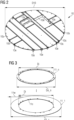
- FIG 2 shows an exemplary embodiment of the platform 10.
- the platform 10 is made by joining multiple platform sections 10s. Some sections 10s are rectangular, with adjacent sections 10s along their straight sides. Other sections 10s are based on a rectangular shape, with three straight sides and one curved edge at the perimeter of the platform 10. The overall shape of the platform 10 is circular with diameter D10.
- the diagram also indicates the manner in which the platform sections 10s are joined.
- the surface of a section 10s extends beyond its straight sides, and these additional areas are bent downwards at right angles to form vertical planar extensions that serve as connecting faces 10e.
- Adjacent platform sections 10s are joined by welding or otherwise connecting their vertical planar connecting faces 10e. The resulting joint provides structural stiffness to the platform 10.
- access openings 10a can be provided in the platform 10, for example to afford passage to a cable arrangement, to allow personnel access, to accommodate a ladder, to accommodate an elevator, etc.
- the downward-bent planar extensions 10e of the platform sections 10s enclosing the access opening 10a serve are shown in the diagram.
- Figure 3 shows a number of adapter rings 11_1, ..., 11_n.
- the inner diameter Di is essentially the same for all adapter rings 11_1, ..., 11_n.
- the outer diameter Do_1, ..., Do_n is different for each adapter ring 11_1, ..., 11_n so that each adapter ring 11_1, ..., 11_n will fit at a different level in the interior of a frustoconical tower.
- the width 11w of an adapter ring 11_1, ..., 11_n can be in the order of 15 cm - 30 cm.
- the inner diameter Di is preferably at most 98% of the platform diameter D10, so that there is sufficient overlap when an instance of the platform 10 rests on an adapter ring 11_1, ..., 11_n.
- an adapter ring can be made of multiple segments, which can be connected by welding and/or by appropriate fasteners. Cut-outs 11c are provided at specific positions that correspond to the positions of the downward-bent extensions 10e of platform sections 10s shown in Figure 2 .
- Figure 4 shows a cross-section through a platform assembly 12_1 installed in a tower 2.
- the diagram illustrates how the outer rim of the platform 10 rests on the upper surface of the adapter ring 11_1, which in turn can rest on or be bolted to a flange (not shown) between tower sections.
- a vertical downward-extending edge 10e of a platform section 10s is secured to a bracket 13 that is mounted to the tower wall.
- the adapter ring 11_1 is provided with a cut-out 11c as shown in Figure 3 , which is shaped and positioned to fit about the vertical downward-extending edge 10e.
- Figure 5 shows a schematic cross-section through a wind turbine tower 2.
- the tower 2 is equipped with an embodiment of the inventive adaptable platform arrangement 1, with a platform assembly 12_1, ..., 12_5 at each of multiple access levels 2L_1, ..., 2L_7.
- the tower 2 is constructed from two right cylindrical sections 21, 22 and two frustoconical sections 23, 24.
- each platform assembly comprises a platform and an adapter ring as explained above.
- platform assemblies 12_1 are installed in the two lower tower sections 21, 22 at access levels 2L_1 - 21_3, i.e. each of these platform assemblies 12_1 uses an adapter ring with the same outer diameter.
- the lowest platform assembly 12_1 rests on a supporting structure 16 installed on the tower foundation and serves as a floor for personnel entering the tower 2; the next platform assembly 12_1 rests on support brackets 13 connected to a tower section flange 27; the next platform assembly 12_1 is suspended by stays 15 secured to suspension fittings 14 mounted to the tower wall.
- platform assemblies 12_2, 12_3 are installed at the next two access levels 2L_4, 2L_5, whereby the outer diameter of the adapter ring of the platform assembly 12_2 at access level 2L_4 is wider than the outer diameter of the adapter ring of the platform assembly 12_3 at access level 2L_5.
- platform assemblies 12_4, 12_5 can be installed as described above, for example suspended by stays 15 secured to suspension fittings 14 mounted to the tower wall, or resting on support brackets 13.
- platform assemblies 12_4, 12_5 are installed at the next two access levels 2L_6, 2L_7, whereby the outer diameter of the adapter ring 11_4 of the platform assembly 12_4 at access level 2L_6 is wider than the outer diameter of the adapter ring 11_5 of the platform assembly 12_5 at access level 2L_7.
- platform assemblies 12_6, 12_7 can be installed as described above, for example suspended by stays 15 secured to suspension fittings 14 mounted to the tower wall, or resting on support brackets 13.
- the diagram also indicates a cable suspension arrangement 28, with power cables extending from the upper level of the tower 2 (from a generator in a nacelle) through openings in the platforms 10, so that the cables can reach the base of the tower 2.
- the tower 2 can also be equipped with an elevator that can pass through openings in the platforms 10, or various ladders that extend from one platform to the next.
- Figure 6 shows a further schematic cross-section through a wind turbine tower 2.
- the tower 2 is equipped with two instances of the inventive adaptable platform arrangement 1A, 1B.
- the upper platform arrangement 1A With the upper platform arrangement 1A, four access levels are installed. The uppermost level uses simply the platform 10A of the adaptable arrangement 1A, and the other three levels use adapter rings 11_1A, 11_2A, 11_3A.
- the uppermost level in this wider tower region uses a platform 10B of the adaptable arrangement 1B with an adapter rings 11_1B.
- the other two levels near the cylindrical base of the tower 2 simply use the platform 10B in each case.
- Figure 7 shows a further schematic cross-section through a wind turbine tower 2 .
- the tower 2 is equipped with two instances of the inventive adaptable platform arrangement 1A, 1B.
- the upper platform arrangement 1A With the upper platform arrangement 1A, four access levels are installed. The uppermost level uses simply the platform 10A of the adaptable arrangement 1A, and the other three levels use adapter rings 11_1A, 11_2A, 11_3A.
- the uppermost level in this wider tower region is provided by only the platform 10B of the adaptable arrangement 1B, and the other two levels use adapter rings 11_1B, 11_2B.
Landscapes
- Engineering & Computer Science (AREA)
- Life Sciences & Earth Sciences (AREA)
- Sustainable Development (AREA)
- Sustainable Energy (AREA)
- Chemical & Material Sciences (AREA)
- Combustion & Propulsion (AREA)
- Mechanical Engineering (AREA)
- General Engineering & Computer Science (AREA)
- Wind Motors (AREA)
Claims (15)
- Anpassbare Turmplattformanordnung (1) zur Verwendung in einem Turminneren (20), umfassend- kreisförmige Plattformen (10) mit jeweils im Wesentlichen identischem Plattformdurchmesser (D10);- eine Vielzahl von ringförmigen Adapterringen (11_1, ..., 11_n) mit jeweils im Wesentlichen demselben Innendurchmesser (Di) und einem Außendurchmesser (Do_1, ..., Do_n), wobei
jeder Außendurchmesser (Do_1, ..., Do_n) den Plattformdurchmesser (D10) überschreitet und einem anderen Turminnendurchmesser (D1, ..., Dn) entspricht; und- eine Montageschnittstelle, die dazu ausgelegt ist, die Verbindung einer Plattform (10) mit einem Adapterring (11_1, ..., 11_n) zu ermöglichen, um eine Plattformbaugruppe (12_1, ..., 12_n) mit dem Außendurchmesser dieses Adapterrings (11_1, ..., 11_n) zu erhalten. - Anpassbare Turmplattformanordnung nach Anspruch 1, wobei die Montageschnittstelle eine ringförmige Überlappung (12o) zwischen einem Adapterring-Innendurchmesser (Di) und dem Plattformdurchmesser (D10) umfasst.
- Anpassbare Turmplattformanordnung nach einem der vorhergehenden Ansprüche, wobei eine Plattform (10) aus einer Vielzahl von Plattformabschnitten (10s) konstruiert ist, wobei ein Plattformabschnitt (10s) mindestens zwei gerade Kanten aufweist, die sich unter einem rechten Winkel treffen.
- Anpassbare Turmplattformanordnung nach Anspruch 3, wobei eine Verbindung zwischen beliebigen zwei benachbarten Plattformabschnitten (10s) zwischen nach unten geklappten Verlängerungen (10e) entlang der geraden Kanten der Plattformabschnitte (10s) gebildet ist.
- Anpassbare Turmplattformanordnung nach einem der vorhergehenden Ansprüche, wobei die Außendurchmesser (Do_1, ..., Do_n) der Adapterringe (11_1, ..., 11_n) auf der Basis eines Turms (2) ausgewählt werden, für den der größte Innendurchmesser in der Größenordnung von 7 m liegt.
- Anpassbare Turmplattformanordnung nach einem der vorhergehenden Ansprüche, wobei die Außendurchmesser (Do_1, ..., Do_n) der Adapterringe (11_1, ..., 11_n) auf der Basis eines Turms (2) ausgewählt werden, für den der kleinste Innendurchmesser in der Größenordnung von 3 m liegt.
- Anpassbare Turmplattformanordnung nach einem der vorhergehenden Ansprüche, wobei der Plattformdurchmesser (D10) höchstens 99 % des kleinsten Innendurchmessers des Turms (2) beträgt.
- Anpassbare Turmplattformanordnung nach einem der vorhergehenden Ansprüche, die eine Installationsschnittstelle (13, 14, 15, 16) zum Installieren einer Plattformbaugruppe (12_1, ..., 12_n) auf einer Ebene (2L_1, ..., 2L_n) in dem Turminneren (20) umfasst.
- Anpassbare Turmplattformanordnung nach einem der vorhergehenden Ansprüche, wobei die Installationsschnittstelle eine Anzahl von Streben (15) umfasst, die dazu ausgelegt sind, sich zwischen der Plattform (10) und der Turmwand zu erstrecken.
- Turm (2), der mit einer anpassbaren Turmplattformanordnung (1) nach einem der Ansprüche 1 bis 9 ausgestattet ist, umfassend eine Vielzahl von Plattformbaugruppen (12_1, ..., 12_n), die auf unterschiedlichen Ebenen (2L_1, ..., 2L_n) im Turminneren (20) installiert sind, wobei jede Plattformbaugruppe (12_1, ..., 12_n) eine kreisförmige Plattform (10) der anpassbaren Turmplattformanordnung (1) umfasst, die an einem Adapterring (11_1, ..., 11_n) der anpassbaren Turmplattformanordnung (1) montiert ist, mit einem Außendurchmesser (Do_1, ..., Do_n), der dem Innendurchmesser des Turms auf dieser Ebene (2L_1, ..., 2L_n) entspricht.
- Turm nach Anspruch 10, umfassend mindestens einen kegelstumpfförmigen Turmabschnitt (23, 24) und zwei oder mehr Plattformbaugruppen (12_2, ..., 12_5), die auf unterschiedlichen Ebenen (2L_4, ..., 2L_7) dieses Turmabschnitts (23, 24) installiert sind.
- Turm nach einem der Ansprüche 10 - 11, umfassend mindestens einen rechten kreisförmigen Turmabschnitt (21, 22) und zwei oder mehr Plattformbaugruppen (12_1), die auf unterschiedlichen Ebenen (2L_1, ..., 2L_3) dieses Turmabschnitts (21, 22) installiert sind, wobei jede Plattformbaugruppe (12_1) denselben Adapterring (11_1) aufweist.
- Turm nach einem der Ansprüche 10 - 12, umfassend eine ringförmige Anordnung von Stützhaltern (13), die sich von der Turmwand nach außen erstrecken, um eine Plattformbaugruppe (12_1, ..., 12_n) aufzunehmen.
- Turm nach einem der Ansprüche 10 - 13, wobei eine Plattform (10) eine Zugangsöffnung (10a), um den Durchgang von Wartungspersonal zwischen verschiedenen Ebenen (2L_1, ..., 2L_n) im Turminneren (20) zu ermöglichen, und/oder eine Öffnung (10a), um den Durchgang von Leistungskabeln (28) zwischen der obersten Ebene des Turms (2) zu der Basis des Turms (2) zu ermöglichen, und/oder eine Zugangsöffnung (10a), die zur Aufnahme eines Aufzugs geformt ist, umfasst.
- Verfahren zum Bereitstellen von Zugang zu einer Ebene (2L_1, ..., 2L_n) in einem Turminneren (20) unter Verwendung einer anpassbaren Turmplattformanordnung (1) nach einem der Ansprüche 1 bis 9, wobei das Verfahren die folgenden Schritte umfasst:- Bestimmen des Turminnendurchmessers (D1, Dn) auf einer Turminnenebene (2L_1, ..., 2L_n);- Vorbereiten einer Plattformbaugruppe (12_1, ..., 12_n) durch Auswählen eines Adapterrings (11_1, ..., 11_n) mit einem Außendurchmesser (Do_1, ..., Do_n), der dem Turminnendurchmesser auf dieser Ebene (2L_1, ..., 2L_n) entspricht, und Montieren einer Instanz der Plattform (10) an dem ausgewählten Adapterring (11_1, ..., 11_n); und- Anordnen der Plattformbaugruppe (12_1, ..., 12_n) auf dieser Turminnenebene (2L_1, ..., 2L_n).
Applications Claiming Priority (2)
| Application Number | Priority Date | Filing Date | Title |
|---|---|---|---|
| EP20382448.7A EP3916221A1 (de) | 2020-05-27 | 2020-05-27 | Anpassbare anordnung einer turmplattform |
| PCT/EP2021/061221 WO2021239381A1 (en) | 2020-05-27 | 2021-04-29 | Adaptable tower platform arrangement |
Publications (2)
| Publication Number | Publication Date |
|---|---|
| EP4136346A1 EP4136346A1 (de) | 2023-02-22 |
| EP4136346B1 true EP4136346B1 (de) | 2025-02-19 |
Family
ID=70921973
Family Applications (2)
| Application Number | Title | Priority Date | Filing Date |
|---|---|---|---|
| EP20382448.7A Pending EP3916221A1 (de) | 2020-05-27 | 2020-05-27 | Anpassbare anordnung einer turmplattform |
| EP21722208.2A Active EP4136346B1 (de) | 2020-05-27 | 2021-04-29 | Anpassbare anordnung einer turmplattform |
Family Applications Before (1)
| Application Number | Title | Priority Date | Filing Date |
|---|---|---|---|
| EP20382448.7A Pending EP3916221A1 (de) | 2020-05-27 | 2020-05-27 | Anpassbare anordnung einer turmplattform |
Country Status (7)
| Country | Link |
|---|---|
| EP (2) | EP3916221A1 (de) |
| JP (1) | JP7481502B2 (de) |
| KR (1) | KR102763138B1 (de) |
| CN (1) | CN115552114A (de) |
| DK (1) | DK4136346T3 (de) |
| PL (1) | PL4136346T3 (de) |
| WO (1) | WO2021239381A1 (de) |
Families Citing this family (1)
| Publication number | Priority date | Publication date | Assignee | Title |
|---|---|---|---|---|
| CN114893357B (zh) * | 2022-03-28 | 2024-08-20 | 上海市机电设计研究院有限公司 | 可变径混凝土塔筒施工平台 |
Family Cites Families (10)
| Publication number | Priority date | Publication date | Assignee | Title |
|---|---|---|---|---|
| ES2283192B1 (es) * | 2005-09-16 | 2008-09-16 | GAMESA INNOVATION & TECHNOLOGY, S.L. | Metodo de montaje de elementos en el interior de la torre de un aerogenerador. |
| US7762037B2 (en) * | 2005-11-18 | 2010-07-27 | General Electric Company | Segment for a tower of a wind energy turbine and method for arranging operating components of a wind energy turbine in a tower thereof |
| US20110140437A1 (en) * | 2010-05-26 | 2011-06-16 | Satish Vemuri | Self-supporting platform for a wind turbine |
| US20130174509A1 (en) * | 2012-01-06 | 2013-07-11 | General Electric Company | Platform assembly for a wind turbine tower |
| SE1251245A1 (sv) * | 2012-11-02 | 2014-05-03 | Sapa Ab | Plattform och metoder för montering i vindturbintorn |
| WO2014122767A1 (ja) * | 2013-02-08 | 2014-08-14 | 三菱重工業株式会社 | 風力発電装置のタワー |
| BR112016022360B1 (pt) * | 2014-04-01 | 2022-12-06 | Nabrawind Technologies SL | Sistema compreendendo uma turbina eólica, método para montagem da ancoragem subaquática de uma turbina eólica marítima e método para montagem de uma turbina eólica |
| CA2997726C (en) * | 2015-08-31 | 2019-10-29 | Siemens Gamesa Renewable Energy, Inc. | Concrete equipment tower with tensioning tendon guide slot |
| US11286915B2 (en) * | 2017-01-18 | 2022-03-29 | Siemens Gamesa Renewable Energy A/S | Standardized platform arrangement of a wind turbine |
| WO2018133965A1 (en) * | 2017-01-18 | 2018-07-26 | Siemens Wind Power A/S | Electrical unit for a wind turbine |
-
2020
- 2020-05-27 EP EP20382448.7A patent/EP3916221A1/de active Pending
-
2021
- 2021-04-29 KR KR1020227043939A patent/KR102763138B1/ko active Active
- 2021-04-29 JP JP2022572590A patent/JP7481502B2/ja active Active
- 2021-04-29 WO PCT/EP2021/061221 patent/WO2021239381A1/en not_active Ceased
- 2021-04-29 EP EP21722208.2A patent/EP4136346B1/de active Active
- 2021-04-29 DK DK21722208.2T patent/DK4136346T3/da active
- 2021-04-29 PL PL21722208.2T patent/PL4136346T3/pl unknown
- 2021-04-29 CN CN202180038484.7A patent/CN115552114A/zh active Pending
Also Published As
| Publication number | Publication date |
|---|---|
| WO2021239381A1 (en) | 2021-12-02 |
| PL4136346T3 (pl) | 2025-04-28 |
| EP3916221A1 (de) | 2021-12-01 |
| EP4136346A1 (de) | 2023-02-22 |
| DK4136346T3 (en) | 2025-03-31 |
| KR20230054797A (ko) | 2023-04-25 |
| JP2023528352A (ja) | 2023-07-04 |
| JP7481502B2 (ja) | 2024-05-10 |
| CN115552114A (zh) | 2022-12-30 |
| KR102763138B1 (ko) | 2025-02-04 |
Similar Documents
| Publication | Publication Date | Title |
|---|---|---|
| US9057205B2 (en) | Platform assembly for a wind turbine tower | |
| EP1668244B1 (de) | Ausrüstung zur anbringung an der nabe einer windturbine und verfahren zur durchführung von wartungsarbeiten an einer windturbine unter verwendung von solcher ausrüstung | |
| CA2568311C (en) | Segment for a tower of a wind energy turbine and method for arranging operating components of a wind energy turbine in a tower thereof | |
| EP2375058A2 (de) | Montage von Komponenten innerhalb einer großen Windkraftanlage | |
| EP2569533B1 (de) | Montageanlage zur montage einer windturbine oder von windturbinenteilen | |
| US11073138B2 (en) | Wind turbine nacelle platform structure | |
| US20110140437A1 (en) | Self-supporting platform for a wind turbine | |
| CN104662290A (zh) | 用于塔的供应架、具有供应架的塔以及用于在塔的内部建造供应架的方法 | |
| US20130174509A1 (en) | Platform assembly for a wind turbine tower | |
| EP3129643B1 (de) | Verfahren zur installation eines leistungssteuerungsmoduls in einem windkraftanlagenturm und aggregatkomponente | |
| EP4136346B1 (de) | Anpassbare anordnung einer turmplattform | |
| US8707656B2 (en) | Safety blanket | |
| US12338800B2 (en) | Wind turbine and method for mounting a platform to a wall portion of a wind turbine | |
| US11905923B2 (en) | Wind turbine tower segment for a wind turbine tower and method | |
| US9869294B2 (en) | Safety structure for performing servicing operations in a wind turbine and method for its installation | |
| FI124115B (fi) | Menetelmä ja moduuli laitteistojen asentamiseksi laivaan | |
| US11859592B2 (en) | Wind turbine | |
| JP7409720B2 (ja) | 塔型風力発電設備の解体方法 | |
| GB2521468A (en) | Support mast | |
| EP4628685A1 (de) | Querverstrebungs- und randträgersystem für fachwerkstrukturen, stahlfachwerkturm und verfahren zum errichten von stahltürmen | |
| EP3904673B1 (de) | Plattform für eine windturbine, windturbine mit dieser plattform und verfahren zum zusammenbau einer windturbine | |
| CN118019906A (zh) | 风力涡轮机叶片、梯支撑组件、风力涡轮机以及用于提供对风力涡轮机的中空叶片内部的通达的方法 |
Legal Events
| Date | Code | Title | Description |
|---|---|---|---|
| STAA | Information on the status of an ep patent application or granted ep patent |
Free format text: STATUS: UNKNOWN |
|
| STAA | Information on the status of an ep patent application or granted ep patent |
Free format text: STATUS: THE INTERNATIONAL PUBLICATION HAS BEEN MADE |
|
| PUAI | Public reference made under article 153(3) epc to a published international application that has entered the european phase |
Free format text: ORIGINAL CODE: 0009012 |
|
| STAA | Information on the status of an ep patent application or granted ep patent |
Free format text: STATUS: REQUEST FOR EXAMINATION WAS MADE |
|
| 17P | Request for examination filed |
Effective date: 20221114 |
|
| AK | Designated contracting states |
Kind code of ref document: A1 Designated state(s): AL AT BE BG CH CY CZ DE DK EE ES FI FR GB GR HR HU IE IS IT LI LT LU LV MC MK MT NL NO PL PT RO RS SE SI SK SM TR |
|
| DAV | Request for validation of the european patent (deleted) | ||
| DAX | Request for extension of the european patent (deleted) | ||
| GRAP | Despatch of communication of intention to grant a patent |
Free format text: ORIGINAL CODE: EPIDOSNIGR1 |
|
| STAA | Information on the status of an ep patent application or granted ep patent |
Free format text: STATUS: GRANT OF PATENT IS INTENDED |
|
| INTG | Intention to grant announced |
Effective date: 20240926 |
|
| GRAS | Grant fee paid |
Free format text: ORIGINAL CODE: EPIDOSNIGR3 |
|
| GRAA | (expected) grant |
Free format text: ORIGINAL CODE: 0009210 |
|
| STAA | Information on the status of an ep patent application or granted ep patent |
Free format text: STATUS: THE PATENT HAS BEEN GRANTED |
|
| AK | Designated contracting states |
Kind code of ref document: B1 Designated state(s): AL AT BE BG CH CY CZ DE DK EE ES FI FR GB GR HR HU IE IS IT LI LT LU LV MC MK MT NL NO PL PT RO RS SE SI SK SM TR |
|
| REG | Reference to a national code |
Ref country code: GB Ref legal event code: FG4D |
|
| REG | Reference to a national code |
Ref country code: CH Ref legal event code: EP |
|
| REG | Reference to a national code |
Ref country code: IE Ref legal event code: FG4D |
|
| REG | Reference to a national code |
Ref country code: DE Ref legal event code: R096 Ref document number: 602021026371 Country of ref document: DE |
|
| REG | Reference to a national code |
Ref country code: DK Ref legal event code: T3 Effective date: 20250327 |
|
| REG | Reference to a national code |
Ref country code: NL Ref legal event code: FP |
|
| PGFP | Annual fee paid to national office [announced via postgrant information from national office to epo] |
Ref country code: NL Payment date: 20250424 Year of fee payment: 5 |
|
| PG25 | Lapsed in a contracting state [announced via postgrant information from national office to epo] |
Ref country code: RS Free format text: LAPSE BECAUSE OF FAILURE TO SUBMIT A TRANSLATION OF THE DESCRIPTION OR TO PAY THE FEE WITHIN THE PRESCRIBED TIME-LIMIT Effective date: 20250519 |
|
| PG25 | Lapsed in a contracting state [announced via postgrant information from national office to epo] |
Ref country code: FI Free format text: LAPSE BECAUSE OF FAILURE TO SUBMIT A TRANSLATION OF THE DESCRIPTION OR TO PAY THE FEE WITHIN THE PRESCRIBED TIME-LIMIT Effective date: 20250219 |
|
| PGFP | Annual fee paid to national office [announced via postgrant information from national office to epo] |
Ref country code: PL Payment date: 20250407 Year of fee payment: 5 Ref country code: DE Payment date: 20250428 Year of fee payment: 5 |
|
| PG25 | Lapsed in a contracting state [announced via postgrant information from national office to epo] |
Ref country code: ES Free format text: LAPSE BECAUSE OF FAILURE TO SUBMIT A TRANSLATION OF THE DESCRIPTION OR TO PAY THE FEE WITHIN THE PRESCRIBED TIME-LIMIT Effective date: 20250219 |
|
| PGFP | Annual fee paid to national office [announced via postgrant information from national office to epo] |
Ref country code: GB Payment date: 20250422 Year of fee payment: 5 Ref country code: DK Payment date: 20250424 Year of fee payment: 5 |
|
| REG | Reference to a national code |
Ref country code: LT Ref legal event code: MG9D |
|
| PG25 | Lapsed in a contracting state [announced via postgrant information from national office to epo] |
Ref country code: IS Free format text: LAPSE BECAUSE OF FAILURE TO SUBMIT A TRANSLATION OF THE DESCRIPTION OR TO PAY THE FEE WITHIN THE PRESCRIBED TIME-LIMIT Effective date: 20250619 Ref country code: NO Free format text: LAPSE BECAUSE OF FAILURE TO SUBMIT A TRANSLATION OF THE DESCRIPTION OR TO PAY THE FEE WITHIN THE PRESCRIBED TIME-LIMIT Effective date: 20250519 |
|
| PG25 | Lapsed in a contracting state [announced via postgrant information from national office to epo] |
Ref country code: HR Free format text: LAPSE BECAUSE OF FAILURE TO SUBMIT A TRANSLATION OF THE DESCRIPTION OR TO PAY THE FEE WITHIN THE PRESCRIBED TIME-LIMIT Effective date: 20250219 |
|
| PG25 | Lapsed in a contracting state [announced via postgrant information from national office to epo] |
Ref country code: LV Free format text: LAPSE BECAUSE OF FAILURE TO SUBMIT A TRANSLATION OF THE DESCRIPTION OR TO PAY THE FEE WITHIN THE PRESCRIBED TIME-LIMIT Effective date: 20250219 Ref country code: PT Free format text: LAPSE BECAUSE OF FAILURE TO SUBMIT A TRANSLATION OF THE DESCRIPTION OR TO PAY THE FEE WITHIN THE PRESCRIBED TIME-LIMIT Effective date: 20250620 |
|
| PGFP | Annual fee paid to national office [announced via postgrant information from national office to epo] |
Ref country code: FR Payment date: 20250424 Year of fee payment: 5 |
|
| PG25 | Lapsed in a contracting state [announced via postgrant information from national office to epo] |
Ref country code: GR Free format text: LAPSE BECAUSE OF FAILURE TO SUBMIT A TRANSLATION OF THE DESCRIPTION OR TO PAY THE FEE WITHIN THE PRESCRIBED TIME-LIMIT Effective date: 20250520 Ref country code: BG Free format text: LAPSE BECAUSE OF FAILURE TO SUBMIT A TRANSLATION OF THE DESCRIPTION OR TO PAY THE FEE WITHIN THE PRESCRIBED TIME-LIMIT Effective date: 20250219 |
|
| REG | Reference to a national code |
Ref country code: AT Ref legal event code: MK05 Ref document number: 1768485 Country of ref document: AT Kind code of ref document: T Effective date: 20250219 |
|
| PG25 | Lapsed in a contracting state [announced via postgrant information from national office to epo] |
Ref country code: SE Free format text: LAPSE BECAUSE OF FAILURE TO SUBMIT A TRANSLATION OF THE DESCRIPTION OR TO PAY THE FEE WITHIN THE PRESCRIBED TIME-LIMIT Effective date: 20250219 |
|
| PG25 | Lapsed in a contracting state [announced via postgrant information from national office to epo] |
Ref country code: SM Free format text: LAPSE BECAUSE OF FAILURE TO SUBMIT A TRANSLATION OF THE DESCRIPTION OR TO PAY THE FEE WITHIN THE PRESCRIBED TIME-LIMIT Effective date: 20250219 |
|
| PG25 | Lapsed in a contracting state [announced via postgrant information from national office to epo] |
Ref country code: IT Free format text: LAPSE BECAUSE OF FAILURE TO SUBMIT A TRANSLATION OF THE DESCRIPTION OR TO PAY THE FEE WITHIN THE PRESCRIBED TIME-LIMIT Effective date: 20250219 |
|
| PG25 | Lapsed in a contracting state [announced via postgrant information from national office to epo] |
Ref country code: AT Free format text: LAPSE BECAUSE OF FAILURE TO SUBMIT A TRANSLATION OF THE DESCRIPTION OR TO PAY THE FEE WITHIN THE PRESCRIBED TIME-LIMIT Effective date: 20250219 |
|
| PG25 | Lapsed in a contracting state [announced via postgrant information from national office to epo] |
Ref country code: EE Free format text: LAPSE BECAUSE OF FAILURE TO SUBMIT A TRANSLATION OF THE DESCRIPTION OR TO PAY THE FEE WITHIN THE PRESCRIBED TIME-LIMIT Effective date: 20250219 Ref country code: CZ Free format text: LAPSE BECAUSE OF FAILURE TO SUBMIT A TRANSLATION OF THE DESCRIPTION OR TO PAY THE FEE WITHIN THE PRESCRIBED TIME-LIMIT Effective date: 20250219 |
|
| PG25 | Lapsed in a contracting state [announced via postgrant information from national office to epo] |
Ref country code: RO Free format text: LAPSE BECAUSE OF FAILURE TO SUBMIT A TRANSLATION OF THE DESCRIPTION OR TO PAY THE FEE WITHIN THE PRESCRIBED TIME-LIMIT Effective date: 20250219 |
|
| PG25 | Lapsed in a contracting state [announced via postgrant information from national office to epo] |
Ref country code: SK Free format text: LAPSE BECAUSE OF FAILURE TO SUBMIT A TRANSLATION OF THE DESCRIPTION OR TO PAY THE FEE WITHIN THE PRESCRIBED TIME-LIMIT Effective date: 20250219 |
|
| REG | Reference to a national code |
Ref country code: DE Ref legal event code: R097 Ref document number: 602021026371 Country of ref document: DE |
|
| REG | Reference to a national code |
Ref country code: CH Ref legal event code: H13 Free format text: ST27 STATUS EVENT CODE: U-0-0-H10-H13 (AS PROVIDED BY THE NATIONAL OFFICE) Effective date: 20251125 |
|
| PG25 | Lapsed in a contracting state [announced via postgrant information from national office to epo] |
Ref country code: LU Free format text: LAPSE BECAUSE OF NON-PAYMENT OF DUE FEES Effective date: 20250429 |
|
| PG25 | Lapsed in a contracting state [announced via postgrant information from national office to epo] |
Ref country code: MC Free format text: LAPSE BECAUSE OF FAILURE TO SUBMIT A TRANSLATION OF THE DESCRIPTION OR TO PAY THE FEE WITHIN THE PRESCRIBED TIME-LIMIT Effective date: 20250219 |
|
| PLBE | No opposition filed within time limit |
Free format text: ORIGINAL CODE: 0009261 |
|
| STAA | Information on the status of an ep patent application or granted ep patent |
Free format text: STATUS: NO OPPOSITION FILED WITHIN TIME LIMIT |
|
| REG | Reference to a national code |
Ref country code: BE Ref legal event code: MM Effective date: 20250430 |
|
| PG25 | Lapsed in a contracting state [announced via postgrant information from national office to epo] |
Ref country code: BE Free format text: LAPSE BECAUSE OF NON-PAYMENT OF DUE FEES Effective date: 20250430 |
|
| PG25 | Lapsed in a contracting state [announced via postgrant information from national office to epo] |
Ref country code: CH Free format text: LAPSE BECAUSE OF NON-PAYMENT OF DUE FEES Effective date: 20250430 |
|
| 26N | No opposition filed |
Effective date: 20251120 |