EP4135633B1 - Abgabevorrichtung mit führungsdrahtsteuerung - Google Patents
Abgabevorrichtung mit führungsdrahtsteuerung Download PDFInfo
- Publication number
- EP4135633B1 EP4135633B1 EP21722611.7A EP21722611A EP4135633B1 EP 4135633 B1 EP4135633 B1 EP 4135633B1 EP 21722611 A EP21722611 A EP 21722611A EP 4135633 B1 EP4135633 B1 EP 4135633B1
- Authority
- EP
- European Patent Office
- Prior art keywords
- guide wire
- delivery device
- handle assembly
- shaft
- actuator
- Prior art date
- Legal status (The legal status is an assumption and is not a legal conclusion. Google has not performed a legal analysis and makes no representation as to the accuracy of the status listed.)
- Active
Links
Images

Classifications
-
- A—HUMAN NECESSITIES
- A61—MEDICAL OR VETERINARY SCIENCE; HYGIENE
- A61F—FILTERS IMPLANTABLE INTO BLOOD VESSELS; PROSTHESES; DEVICES PROVIDING PATENCY TO, OR PREVENTING COLLAPSING OF, TUBULAR STRUCTURES OF THE BODY, e.g. STENTS; ORTHOPAEDIC, NURSING OR CONTRACEPTIVE DEVICES; FOMENTATION; TREATMENT OR PROTECTION OF EYES OR EARS; BANDAGES, DRESSINGS OR ABSORBENT PADS; FIRST-AID KITS
- A61F2/00—Filters implantable into blood vessels; Prostheses, i.e. artificial substitutes or replacements for parts of the body; Appliances for connecting them with the body; Devices providing patency to, or preventing collapsing of, tubular structures of the body, e.g. stents
- A61F2/95—Instruments specially adapted for placement or removal of stents or stent-grafts
- A61F2/9517—Instruments specially adapted for placement or removal of stents or stent-grafts handle assemblies therefor
-
- A—HUMAN NECESSITIES
- A61—MEDICAL OR VETERINARY SCIENCE; HYGIENE
- A61F—FILTERS IMPLANTABLE INTO BLOOD VESSELS; PROSTHESES; DEVICES PROVIDING PATENCY TO, OR PREVENTING COLLAPSING OF, TUBULAR STRUCTURES OF THE BODY, e.g. STENTS; ORTHOPAEDIC, NURSING OR CONTRACEPTIVE DEVICES; FOMENTATION; TREATMENT OR PROTECTION OF EYES OR EARS; BANDAGES, DRESSINGS OR ABSORBENT PADS; FIRST-AID KITS
- A61F2/00—Filters implantable into blood vessels; Prostheses, i.e. artificial substitutes or replacements for parts of the body; Appliances for connecting them with the body; Devices providing patency to, or preventing collapsing of, tubular structures of the body, e.g. stents
- A61F2/02—Prostheses implantable into the body
- A61F2/24—Heart valves ; Vascular valves, e.g. venous valves; Heart implants, e.g. passive devices for improving the function of the native valve or the heart muscle; Transmyocardial revascularisation [TMR] devices; Valves implantable in the body
- A61F2/2427—Devices for manipulating or deploying heart valves during implantation
- A61F2/2436—Deployment by retracting a sheath
-
- A—HUMAN NECESSITIES
- A61—MEDICAL OR VETERINARY SCIENCE; HYGIENE
- A61M—DEVICES FOR INTRODUCING MEDIA INTO, OR ONTO, THE BODY; DEVICES FOR TRANSDUCING BODY MEDIA OR FOR TAKING MEDIA FROM THE BODY; DEVICES FOR PRODUCING OR ENDING SLEEP OR STUPOR
- A61M25/00—Catheters; Hollow probes
- A61M25/01—Introducing, guiding, advancing, emplacing or holding catheters
- A61M25/09—Guide wires
- A61M2025/09116—Design of handles or shafts or gripping surfaces thereof for manipulating guide wires
-
- A—HUMAN NECESSITIES
- A61—MEDICAL OR VETERINARY SCIENCE; HYGIENE
- A61M—DEVICES FOR INTRODUCING MEDIA INTO, OR ONTO, THE BODY; DEVICES FOR TRANSDUCING BODY MEDIA OR FOR TAKING MEDIA FROM THE BODY; DEVICES FOR PRODUCING OR ENDING SLEEP OR STUPOR
- A61M25/00—Catheters; Hollow probes
- A61M25/01—Introducing, guiding, advancing, emplacing or holding catheters
- A61M25/09—Guide wires
- A61M2025/09125—Device for locking a guide wire in a fixed position with respect to the catheter or the human body
Definitions
- the present technology is generally related to transcatheter prosthesis delivery devices and methods controlling a guide wire of the delivery device.
- Heart valve replacement surgery is an open-heart procedure conducted under general anesthesia, during which the heart is stopped and blood flow is controlled by a heart-lung bypass machine.
- Traditional open surgery inflicts significant patient trauma and discomfort, and exposes the patient to a number of potential risks, such as infection, stroke, renal failure, and adverse effects associated with the use of the heart-lung bypass machine, for example.
- a prosthetic heart valve is compacted for delivery in a catheter and then advanced, for example, through an opening in the femoral artery and through the descending aorta to the heart, where the prosthetic heart valve is then deployed in the annulus of the valve to be restored (e.g., the aortic valve annulus).
- transcatheter techniques have attained widespread acceptance with respect to the delivery of conventional stents to restore vessel patency, only mixed results have been realized with percutaneous delivery of the more complex prosthetic heart valve.
- US 2019/0365550 A1 describes a guidewire adjuster and delivery-system control handle.
- US 2015/ 0306358 A1 describes a control module for delivery systems.
- the techniques of this disclosure generally relate to delivery devices for transcatheter delivery of a prosthesis.
- the delivery device includes a hollow shaft on which the prosthesis is supported.
- a handle assembly maintains the shaft.
- the delivery device further includes a guide wire that is selectively directed through the handle assembly and shaft.
- the guide wire directs the shaft to a target site at which the prosthesis is to be deployed.
- an operator managing the shaft or inner catheter controls the prosthesis positioning.
- the delivery devices disclosed herein are configured to ergonomically also allow the operator to control the position of the guide wire as the position of the guide wire influences the deployment position of the prosthesis. In this way, a second operator for positioning the guide wire can be omitted.
- Embodiments of the disclosure are believed to improve positioning predictability and ease of use.
- the invention is directed to a delivery device according to independent claim 1.
- the disclosure provides methods of controlling a guide wire.
- the method can include providing a delivery device having a handle assembly with a distal end and a proximal end.
- the handle assembly further including a body defining a lumen that extends from the distal end to the proximal end.
- the delivery device further includes a hollow shaft extending from the distal end of the handle assembly and a guide wire control.
- the guide wire control includes an actuator positioned at the distal end of the handle assembly and a lock positioned at the proximal end of the handle assembly.
- the actuator being interconnected to the lock with a connector positioned within the lumen.
- the guide wire control is provided in an unlocked state.
- the method further includes positioning a guide wire through the lumen and directing the guide wire through the lumen and into a vasculature of a patient proximate a target site by movement of the actuator.
- the method also includes transitioning the lock to the locked state.
- distal and proximal are used in the following description with respect to a position or direction relative to the treating clinician.
- distal or disally are a position distant from or in a direction away from the clinician.
- Proximal and “proximally” are a position near or in a direction toward the clinician.
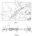
- FIG. 1 illustrates two clinicians C1, C2 utilizing a delivery device 10 to deliver a prosthesis via a transcatehter procedure.
- the delivery device 10 can be of any known in the art that includes a handle assembly 12 connected to a hollow shaft 14 or the like on which the prosthesis (not visible) is supported.
- a guide wire 16 is provided and can be extended through the handle assembly 12 and shaft 14.
- the prosthesis is supported on the shaft 14 and an outer catheter (not shown) is provided to selectively sheathe the shaft 14 and prosthesis.
- the prosthesis could be one of a number of prosthesis such as a stent, prosthetic heart valve, for example.
- the first clinician C1 manages and controls the shaft 14 and outer catheter management.
- the first operator C1 controls a depth of the shaft (and optional outer catheter) during prosthesis deployment.
- a second operator C2 directs a guide wire 16 through a proximal end of a handle assembly 12 of the device to a distal end of the device 10, through the patient's vasculature to a target site.
- the second clinician C2 uses the guide wire for fine adjustment of the shaft/optional outer catheter and tension adjustment. It has been observed that with use of such delivery devices, the first operator C 1 usually holds onto the shaft 14 or outer catheter with one hand and reaches with an underhanded grip to the guide wire 16. Then, the first operator C1 reaches over the second clinician C2 to move the guide wire 16, which is ergonomically awkward.
- a third clinician C3 is provided to retract an outer catheter, if provided.
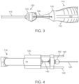
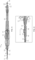
- FIGS. 2-8 collectively illustrate a delivery device 110 for transcatheter delivery of a prosthesis 111.
- the delivery device 110 includes a hollow shaft 112 on which the prosthesis 111 is supported. It is noted that in Figure 5 the shaft 112 is not shown to scale and shaft 112 is shown as foreshortened for ease of illustration. The shaft 112 may be significantly longer in practice.
- the delivery device 110 can further include an outer catheter (not shown) selectively sheathing the shaft 112 and prosthesis 111 during delivery.
- a handle assembly 114 maintains the shaft 112 and outer catheter. In some embodiments, the handle assembly 114 is configured to allow an operator to control movement of the outer catheter with respect to the shaft 112.
- the handle assembly 114 includes a body 116 having a distal and proximal end 118, 120.
- the body 116 defines an interior lumen 122 extending through the proximal end 120 and through the distal end 118.
- the delivery device 110 further includes a guide wire 124 that is selectively directed through the lumen 122 of the handle assembly 114 and through the shaft 112. It is envisioned that the guide wire 124 can be provided separate from the delivery device 110.
- the guide wire 124 is threaded through the hollow shaft 112 to direct the prosthesis 111 to a target site at which the prosthesis 111 is to be deployed. In practice, an operator managing the shaft 112 controls the prosthesis 111 positioning.
- the delivery devices disclosed herein are configured to ergonomically also allow the operator to control the position of the guide wire as the position of the guide wire influences the deployment position of the prosthesis. In this way, a second operator for positioning the guide wire can be omitted.
- Embodiments of the disclosure are believed to improve positioning predictability and ease of use.
- the delivery device 1110 includes a guide wire control 130 including an actuator 132 at the distal end 118 of the body 116 of the handle assembly 114.
- the actuator 132 is positioned on the shaft 112.
- the actuator 132 is configured to control advancement of the guide wire 124.
- the actuator 132 has thumbwheel 134 secured to a slider 138 (schematically shown) that engages and advances the guide wire 124 routed through an opening or lumen 139 in the slider 138.
- thumbwheel 134 is the diving pinion and the rack is attached to the guide wire 124. Any other actuator capable of advancing the guide wire 124 and connection to the connector 140 is suitable.
- the guide wire control 130 further includes a connector 140 extending through the lumen 122 of the body 116 and interconnecting the actuator 132 to a lock 142 that is positioned at a proximal end 120 of the body 116.
- the connector 140 can be welded or otherwise secured to both the actuator 132 and the lock 142.
- the lock 142 is mounted to one or more support rods 143 extending from the proximal end 120.
- the connector 140 includes a lumen 144 through which the guide wire 124 is routed. In such embodiments, the lumen 144 of the connector 140 is coaxial with the lumen 139 of the actuator/slider 138.
- the connector 140 is not hollow but is a rod (i.e.
- the lock 142 includes a lumen or opening 146 through which the guide wire 124 is routed and is configured to have an unlocked state in which the guide wire 124 can move longitudinally through both the lumens 146, 122, 139 of the lock 142, the body 116 and slider 138.
- the lock 142 is further configured to have a locked state in which the guide wire 124 is locked and maintained in longitudinal position with respect to both the handle assembly 114 and the shaft 112.
- the lock 142 is left in its unlocked state until the shaft 112 is tracked and in its initial position, proximate a target site.
- the guide wire 124 is then locked with the lock 142 allowing an operator to take over from the patient side (i.e. distal end 118 of the handle assembly 114) allowing for single operator positioning control during prosthesis deployment.
- the lock 142 can be a Tuohy Borst type connector.
- the devices (e.g., delivery device 110) of the disclosure can be used in methods of controlling a guide wire 124.
- the method can include providing the delivery device 110.
- the prosthesis 111 such as a stent or prosthetic heart valve, for example, can be provided on or collapsed onto the shaft 112.
- the guide wire control 130 is provided in the unlocked state.
- the method further includes positioning the guide wire 124 through the lumens 146, 122, 139 of the lock 142, handle assembly 114 and actuator 132 and directing the guide wire 124 into a vasculature of a patient proximate a target site by movement or other actuation of the actuator 132.
- the guide wire 124 can also be routed through the connector 140.
- the shaft 112 is advanced along the guide wire 124 until the prosthesis 111 is guided to the target site for deployment.
- the method also includes transitioning the lock 142 to the locked state so that the longitudinal position of the guide wire 124 is maintained with respect to the handle assembly 114 and the shaft 112 during shaft/prosthesis 112/111 positioning and prosthesis 111 deployment.
Landscapes
- Health & Medical Sciences (AREA)
- Cardiology (AREA)
- Engineering & Computer Science (AREA)
- Biomedical Technology (AREA)
- Heart & Thoracic Surgery (AREA)
- Transplantation (AREA)
- Oral & Maxillofacial Surgery (AREA)
- Vascular Medicine (AREA)
- Life Sciences & Earth Sciences (AREA)
- Animal Behavior & Ethology (AREA)
- General Health & Medical Sciences (AREA)
- Public Health (AREA)
- Veterinary Medicine (AREA)
- Media Introduction/Drainage Providing Device (AREA)
- Prostheses (AREA)
Claims (10)
- Abgabevorrichtung (110), umfassend:eine Griffanordnung (114), die ein distales Ende (118) und ein proximales Ende (120) aufweist, wobei die Griffanordnung ferner einen Körper (116) einschließt, der ein Lumen (122) definiert, das sich von dem distalen Ende zu dem proximalen Ende erstreckt;einen hohlen Schaft (112), der sich von dem distalen Ende der Griffanordnung erstreckt;einen Führungsdraht (124), der sich durch das Lumen hindurch erstreckt; undeine Führungsdrahtsteuerung (130); wobei die Führungsdrahtsteuerung einen Aktuator (132), der an dem distalen Ende der Griffanordnung positioniert ist, und eine Sperre (142) einschließt, die an dem proximalen Ende der Griffanordnung positioniert ist, wobei der Aktuator mit der Sperre mit einem Verbinder (140) verbunden ist, der innerhalb des Lumens positioniert ist; wobei die Führungsdrahtsteuerung einen entsperrten Zustand aufweist, in dem sich der Führungsdraht (124) in Längsrichtung durch das Lumen (122) des Körpers (116) hindurch und durch ein Lumen (146) der Sperre (142) hindurch bewegen kann, und wobei die Führungsdrahtsteuerung ferner einen gesperrten Zustand aufweist, in dem der Führungsdraht (124) mit der Sperre (142) gesperrt ist und in dem der Aktuator konfiguriert ist, um eine Vorwärtsbewegung des Führungsdrahts (124) zu steuern.
- Abgabevorrichtung nach Anspruch 1, wobei der Aktuator ein Rändelrad (134) einschließt.
- Abgabevorrichtung nach Anspruch 1, wobei der Aktuator einen Schieber (138) einschließt, der über dem Schaft montiert ist.
- Abgabevorrichtung nach Anspruch 1, wobei der Verbinder ein starrer Schaft ist.
- Abgabevorrichtung nach Anspruch 1, wobei der Verbinder ein Rohr ist.
- Abgabevorrichtung nach Anspruch 5, wobei das Rohr ein Hypotube ist.
- Abgabevorrichtung nach Anspruch 5, wobei der Führungsdraht durch das Rohr hindurch verläuft.
- Abgabevorrichtung nach Anspruch 5, wobei sich das Rohr von dem distalen Ende zu dem proximalen Ende des Körpers der Griffanordnung erstreckt.
- Abgabevorrichtung nach Anspruch 1, wobei die Sperre einen Tuohy-Borst-Verbinder einschließt.
- Abgabevorrichtung nach Anspruch 1, wobei der Aktuator auf dem Schaft positioniert ist.
Applications Claiming Priority (3)
| Application Number | Priority Date | Filing Date | Title |
|---|---|---|---|
| US202063010325P | 2020-04-15 | 2020-04-15 | |
| US17/179,613 US12023244B2 (en) | 2020-04-15 | 2021-02-19 | Delivery device having guide wire control |
| PCT/US2021/025720 WO2021211313A1 (en) | 2020-04-15 | 2021-04-05 | Delivery device having guide wire control |
Publications (2)
| Publication Number | Publication Date |
|---|---|
| EP4135633A1 EP4135633A1 (de) | 2023-02-22 |
| EP4135633B1 true EP4135633B1 (de) | 2024-12-11 |
Family
ID=78080669
Family Applications (1)
| Application Number | Title | Priority Date | Filing Date |
|---|---|---|---|
| EP21722611.7A Active EP4135633B1 (de) | 2020-04-15 | 2021-04-05 | Abgabevorrichtung mit führungsdrahtsteuerung |
Country Status (4)
| Country | Link |
|---|---|
| US (1) | US12023244B2 (de) |
| EP (1) | EP4135633B1 (de) |
| CN (1) | CN115413233A (de) |
| WO (1) | WO2021211313A1 (de) |
Families Citing this family (1)
| Publication number | Priority date | Publication date | Assignee | Title |
|---|---|---|---|---|
| CN118524820A (zh) * | 2022-01-10 | 2024-08-20 | 吉菲斯坦私人有限公司 | 支架插入装置和方法 |
Family Cites Families (12)
| Publication number | Priority date | Publication date | Assignee | Title |
|---|---|---|---|---|
| US5201757A (en) | 1992-04-03 | 1993-04-13 | Schneider (Usa) Inc. | Medial region deployment of radially self-expanding stents |
| US6752800B1 (en) | 2000-02-18 | 2004-06-22 | Intraluminal Therapeutics Inc. | Catheter handle for controlling the advancement of a guide wire |
| US6533772B1 (en) | 2000-04-07 | 2003-03-18 | Innex Corporation | Guide wire torque device |
| US9872971B2 (en) | 2010-05-14 | 2018-01-23 | C. R. Bard, Inc. | Guidewire extension system for a catheter placement device |
| US9308087B2 (en) * | 2011-04-28 | 2016-04-12 | Neovasc Tiara Inc. | Sequentially deployed transcatheter mitral valve prosthesis |
| CN105392518A (zh) | 2012-10-02 | 2016-03-09 | 女王医疗中心 | 具有引导线防滑脱特征的脉管通路系统 |
| US9144493B2 (en) * | 2012-11-14 | 2015-09-29 | Medtronic Vascular Galway Limited | Valve prosthesis deployment assembly and method |
| US9603600B2 (en) | 2013-11-20 | 2017-03-28 | James E. Coleman | Actuator for deployable implant |
| US10159819B2 (en) | 2014-04-24 | 2018-12-25 | Medtronic Vascular Galway | Control module for delivery systems |
| US9919130B2 (en) * | 2016-01-25 | 2018-03-20 | Michael Ring | Catheter guide wire control device |
| CN106580375B (zh) | 2016-12-15 | 2020-09-22 | 杭州启明医疗器械股份有限公司 | 一种导丝调节器以及输送系统控制手柄 |
| EP3508172B1 (de) | 2018-01-03 | 2020-08-19 | Cook Medical Technologies LLC | Vorgeladene freisetzungsvorrichtung mit mehreren anschlüssen |
-
2021
- 2021-02-19 US US17/179,613 patent/US12023244B2/en active Active
- 2021-04-05 CN CN202180027665.XA patent/CN115413233A/zh active Pending
- 2021-04-05 WO PCT/US2021/025720 patent/WO2021211313A1/en not_active Ceased
- 2021-04-05 EP EP21722611.7A patent/EP4135633B1/de active Active
Also Published As
| Publication number | Publication date |
|---|---|
| US12023244B2 (en) | 2024-07-02 |
| EP4135633A1 (de) | 2023-02-22 |
| WO2021211313A1 (en) | 2021-10-21 |
| CN115413233A (zh) | 2022-11-29 |
| US20210322165A1 (en) | 2021-10-21 |
Similar Documents
| Publication | Publication Date | Title |
|---|---|---|
| JP6341211B2 (ja) | 人工心弁移植用ガイドワイヤシステムを心室内部に配置させるための装置 | |
| JP6434589B2 (ja) | 心弁置換用人工器官システム | |
| EP2563236B1 (de) | Vorrichtung für herzklappenreparatur oder -ersatz | |
| EP2699200B1 (de) | Transkatheter-freisetzungssystem mit spülport für eine herzklappenprothese | |
| US20210137681A1 (en) | Delivery Systems and Methods fro Transseptal Access to a Left Atrium | |
| US8808367B2 (en) | Prosthetic valve delivery system including retrograde/antegrade approach | |
| EP4157149B1 (de) | Protheseneinführungsvorrichtung | |
| US10258490B2 (en) | Split sheath prosthesis deployment system with divided tip | |
| IL292931A (en) | Transporting a medical implant using a catheter | |
| US20090069889A1 (en) | Streamlined, apical delivery system for in situ deployment of cardiac valve prostheses | |
| US20030163085A1 (en) | Catheter hand-piece apparatus and method of using the same | |
| CN110996855A (zh) | 可操纵轨道递送系统 | |
| US20140088684A1 (en) | Catheter system | |
| US20250177140A1 (en) | Annuloplasty manual internal guidewire navigation | |
| EP4135633B1 (de) | Abgabevorrichtung mit führungsdrahtsteuerung | |
| EP4496614A1 (de) | Katheter, kathetergriff und verfahren zur navigation eines katheters | |
| US20240225831A1 (en) | Surgical system for a heart valve | |
| CN115737208A (zh) | 一种可精准调控的植入器械输送系统 | |
| US20230030295A1 (en) | Tyne docking for percutaneous coronary intervention access | |
| EP4401678A1 (de) | Katheteranordnungen zur transkatheterfreisetzung und verfahren zur einschränkung der kapselbewegung |
Legal Events
| Date | Code | Title | Description |
|---|---|---|---|
| STAA | Information on the status of an ep patent application or granted ep patent |
Free format text: STATUS: UNKNOWN |
|
| STAA | Information on the status of an ep patent application or granted ep patent |
Free format text: STATUS: THE INTERNATIONAL PUBLICATION HAS BEEN MADE |
|
| PUAI | Public reference made under article 153(3) epc to a published international application that has entered the european phase |
Free format text: ORIGINAL CODE: 0009012 |
|
| STAA | Information on the status of an ep patent application or granted ep patent |
Free format text: STATUS: REQUEST FOR EXAMINATION WAS MADE |
|
| 17P | Request for examination filed |
Effective date: 20221109 |
|
| AK | Designated contracting states |
Kind code of ref document: A1 Designated state(s): AL AT BE BG CH CY CZ DE DK EE ES FI FR GB GR HR HU IE IS IT LI LT LU LV MC MK MT NL NO PL PT RO RS SE SI SK SM TR |
|
| DAV | Request for validation of the european patent (deleted) | ||
| DAX | Request for extension of the european patent (deleted) | ||
| STAA | Information on the status of an ep patent application or granted ep patent |
Free format text: STATUS: EXAMINATION IS IN PROGRESS |
|
| 17Q | First examination report despatched |
Effective date: 20231124 |
|
| GRAP | Despatch of communication of intention to grant a patent |
Free format text: ORIGINAL CODE: EPIDOSNIGR1 |
|
| STAA | Information on the status of an ep patent application or granted ep patent |
Free format text: STATUS: GRANT OF PATENT IS INTENDED |
|
| INTG | Intention to grant announced |
Effective date: 20240710 |
|
| GRAS | Grant fee paid |
Free format text: ORIGINAL CODE: EPIDOSNIGR3 |
|
| GRAA | (expected) grant |
Free format text: ORIGINAL CODE: 0009210 |
|
| STAA | Information on the status of an ep patent application or granted ep patent |
Free format text: STATUS: THE PATENT HAS BEEN GRANTED |
|
| AK | Designated contracting states |
Kind code of ref document: B1 Designated state(s): AL AT BE BG CH CY CZ DE DK EE ES FI FR GB GR HR HU IE IS IT LI LT LU LV MC MK MT NL NO PL PT RO RS SE SI SK SM TR |
|
| REG | Reference to a national code |
Ref country code: GB Ref legal event code: FG4D |
|
| REG | Reference to a national code |
Ref country code: CH Ref legal event code: EP |
|
| REG | Reference to a national code |
Ref country code: DE Ref legal event code: R096 Ref document number: 602021023260 Country of ref document: DE |
|
| REG | Reference to a national code |
Ref country code: IE Ref legal event code: FG4D |
|
| REG | Reference to a national code |
Ref country code: LT Ref legal event code: MG9D |
|
| PG25 | Lapsed in a contracting state [announced via postgrant information from national office to epo] |
Ref country code: HR Free format text: LAPSE BECAUSE OF FAILURE TO SUBMIT A TRANSLATION OF THE DESCRIPTION OR TO PAY THE FEE WITHIN THE PRESCRIBED TIME-LIMIT Effective date: 20241211 |
|
| PG25 | Lapsed in a contracting state [announced via postgrant information from national office to epo] |
Ref country code: FI Free format text: LAPSE BECAUSE OF FAILURE TO SUBMIT A TRANSLATION OF THE DESCRIPTION OR TO PAY THE FEE WITHIN THE PRESCRIBED TIME-LIMIT Effective date: 20241211 |
|
| PG25 | Lapsed in a contracting state [announced via postgrant information from national office to epo] |
Ref country code: BG Free format text: LAPSE BECAUSE OF FAILURE TO SUBMIT A TRANSLATION OF THE DESCRIPTION OR TO PAY THE FEE WITHIN THE PRESCRIBED TIME-LIMIT Effective date: 20241211 |
|
| REG | Reference to a national code |
Ref country code: NL Ref legal event code: MP Effective date: 20241211 |
|
| PG25 | Lapsed in a contracting state [announced via postgrant information from national office to epo] |
Ref country code: ES Free format text: LAPSE BECAUSE OF FAILURE TO SUBMIT A TRANSLATION OF THE DESCRIPTION OR TO PAY THE FEE WITHIN THE PRESCRIBED TIME-LIMIT Effective date: 20241211 |
|
| PGFP | Annual fee paid to national office [announced via postgrant information from national office to epo] |
Ref country code: IE Payment date: 20250321 Year of fee payment: 5 |
|
| PG25 | Lapsed in a contracting state [announced via postgrant information from national office to epo] |
Ref country code: NO Free format text: LAPSE BECAUSE OF FAILURE TO SUBMIT A TRANSLATION OF THE DESCRIPTION OR TO PAY THE FEE WITHIN THE PRESCRIBED TIME-LIMIT Effective date: 20250311 |
|
| PG25 | Lapsed in a contracting state [announced via postgrant information from national office to epo] |
Ref country code: LV Free format text: LAPSE BECAUSE OF FAILURE TO SUBMIT A TRANSLATION OF THE DESCRIPTION OR TO PAY THE FEE WITHIN THE PRESCRIBED TIME-LIMIT Effective date: 20241211 Ref country code: GR Free format text: LAPSE BECAUSE OF FAILURE TO SUBMIT A TRANSLATION OF THE DESCRIPTION OR TO PAY THE FEE WITHIN THE PRESCRIBED TIME-LIMIT Effective date: 20250312 |
|
| PGFP | Annual fee paid to national office [announced via postgrant information from national office to epo] |
Ref country code: FR Payment date: 20250319 Year of fee payment: 5 |
|
| PG25 | Lapsed in a contracting state [announced via postgrant information from national office to epo] |
Ref country code: RS Free format text: LAPSE BECAUSE OF FAILURE TO SUBMIT A TRANSLATION OF THE DESCRIPTION OR TO PAY THE FEE WITHIN THE PRESCRIBED TIME-LIMIT Effective date: 20250311 |
|
| PG25 | Lapsed in a contracting state [announced via postgrant information from national office to epo] |
Ref country code: NL Free format text: LAPSE BECAUSE OF FAILURE TO SUBMIT A TRANSLATION OF THE DESCRIPTION OR TO PAY THE FEE WITHIN THE PRESCRIBED TIME-LIMIT Effective date: 20241211 |
|
| REG | Reference to a national code |
Ref country code: AT Ref legal event code: MK05 Ref document number: 1749783 Country of ref document: AT Kind code of ref document: T Effective date: 20241211 |
|
| PG25 | Lapsed in a contracting state [announced via postgrant information from national office to epo] |
Ref country code: SM Free format text: LAPSE BECAUSE OF FAILURE TO SUBMIT A TRANSLATION OF THE DESCRIPTION OR TO PAY THE FEE WITHIN THE PRESCRIBED TIME-LIMIT Effective date: 20241211 |
|
| PG25 | Lapsed in a contracting state [announced via postgrant information from national office to epo] |
Ref country code: PL Free format text: LAPSE BECAUSE OF FAILURE TO SUBMIT A TRANSLATION OF THE DESCRIPTION OR TO PAY THE FEE WITHIN THE PRESCRIBED TIME-LIMIT Effective date: 20241211 |
|
| PGFP | Annual fee paid to national office [announced via postgrant information from national office to epo] |
Ref country code: DE Payment date: 20250319 Year of fee payment: 5 |
|
| PG25 | Lapsed in a contracting state [announced via postgrant information from national office to epo] |
Ref country code: IS Free format text: LAPSE BECAUSE OF FAILURE TO SUBMIT A TRANSLATION OF THE DESCRIPTION OR TO PAY THE FEE WITHIN THE PRESCRIBED TIME-LIMIT Effective date: 20250411 |
|
| PG25 | Lapsed in a contracting state [announced via postgrant information from national office to epo] |
Ref country code: PT Free format text: LAPSE BECAUSE OF FAILURE TO SUBMIT A TRANSLATION OF THE DESCRIPTION OR TO PAY THE FEE WITHIN THE PRESCRIBED TIME-LIMIT Effective date: 20250411 |
|
| PG25 | Lapsed in a contracting state [announced via postgrant information from national office to epo] |
Ref country code: EE Free format text: LAPSE BECAUSE OF FAILURE TO SUBMIT A TRANSLATION OF THE DESCRIPTION OR TO PAY THE FEE WITHIN THE PRESCRIBED TIME-LIMIT Effective date: 20241211 |
|
| PG25 | Lapsed in a contracting state [announced via postgrant information from national office to epo] |
Ref country code: AT Free format text: LAPSE BECAUSE OF FAILURE TO SUBMIT A TRANSLATION OF THE DESCRIPTION OR TO PAY THE FEE WITHIN THE PRESCRIBED TIME-LIMIT Effective date: 20241211 Ref country code: RO Free format text: LAPSE BECAUSE OF FAILURE TO SUBMIT A TRANSLATION OF THE DESCRIPTION OR TO PAY THE FEE WITHIN THE PRESCRIBED TIME-LIMIT Effective date: 20241211 |
|
| PG25 | Lapsed in a contracting state [announced via postgrant information from national office to epo] |
Ref country code: SK Free format text: LAPSE BECAUSE OF FAILURE TO SUBMIT A TRANSLATION OF THE DESCRIPTION OR TO PAY THE FEE WITHIN THE PRESCRIBED TIME-LIMIT Effective date: 20241211 |
|
| PG25 | Lapsed in a contracting state [announced via postgrant information from national office to epo] |
Ref country code: CZ Free format text: LAPSE BECAUSE OF FAILURE TO SUBMIT A TRANSLATION OF THE DESCRIPTION OR TO PAY THE FEE WITHIN THE PRESCRIBED TIME-LIMIT Effective date: 20241211 |
|
| PG25 | Lapsed in a contracting state [announced via postgrant information from national office to epo] |
Ref country code: IT Free format text: LAPSE BECAUSE OF FAILURE TO SUBMIT A TRANSLATION OF THE DESCRIPTION OR TO PAY THE FEE WITHIN THE PRESCRIBED TIME-LIMIT Effective date: 20241211 |
|
| PG25 | Lapsed in a contracting state [announced via postgrant information from national office to epo] |
Ref country code: SE Free format text: LAPSE BECAUSE OF FAILURE TO SUBMIT A TRANSLATION OF THE DESCRIPTION OR TO PAY THE FEE WITHIN THE PRESCRIBED TIME-LIMIT Effective date: 20241211 |
|
| REG | Reference to a national code |
Ref country code: DE Ref legal event code: R097 Ref document number: 602021023260 Country of ref document: DE |
|
| PG25 | Lapsed in a contracting state [announced via postgrant information from national office to epo] |
Ref country code: DK Free format text: LAPSE BECAUSE OF FAILURE TO SUBMIT A TRANSLATION OF THE DESCRIPTION OR TO PAY THE FEE WITHIN THE PRESCRIBED TIME-LIMIT Effective date: 20241211 |
|
| PLBE | No opposition filed within time limit |
Free format text: ORIGINAL CODE: 0009261 |
|
| STAA | Information on the status of an ep patent application or granted ep patent |
Free format text: STATUS: NO OPPOSITION FILED WITHIN TIME LIMIT |
|
| REG | Reference to a national code |
Ref country code: CH Ref legal event code: L10 Free format text: ST27 STATUS EVENT CODE: U-0-0-L10-L00 (AS PROVIDED BY THE NATIONAL OFFICE) Effective date: 20251022 |
|
| 26N | No opposition filed |
Effective date: 20250912 |
|
| REG | Reference to a national code |
Ref country code: CH Ref legal event code: H13 Free format text: ST27 STATUS EVENT CODE: U-0-0-H10-H13 (AS PROVIDED BY THE NATIONAL OFFICE) Effective date: 20251125 |
|
| PG25 | Lapsed in a contracting state [announced via postgrant information from national office to epo] |
Ref country code: LU Free format text: LAPSE BECAUSE OF NON-PAYMENT OF DUE FEES Effective date: 20250405 |
|
| PG25 | Lapsed in a contracting state [announced via postgrant information from national office to epo] |
Ref country code: MC Free format text: LAPSE BECAUSE OF FAILURE TO SUBMIT A TRANSLATION OF THE DESCRIPTION OR TO PAY THE FEE WITHIN THE PRESCRIBED TIME-LIMIT Effective date: 20241211 |
|
| GBPC | Gb: european patent ceased through non-payment of renewal fee |
Effective date: 20250405 |
|
| REG | Reference to a national code |
Ref country code: BE Ref legal event code: MM Effective date: 20250430 |
|
| PG25 | Lapsed in a contracting state [announced via postgrant information from national office to epo] |
Ref country code: GB Free format text: LAPSE BECAUSE OF NON-PAYMENT OF DUE FEES Effective date: 20250405 |
|
| PG25 | Lapsed in a contracting state [announced via postgrant information from national office to epo] |
Ref country code: BE Free format text: LAPSE BECAUSE OF NON-PAYMENT OF DUE FEES Effective date: 20250430 |
|
| PG25 | Lapsed in a contracting state [announced via postgrant information from national office to epo] |
Ref country code: CH Free format text: LAPSE BECAUSE OF NON-PAYMENT OF DUE FEES Effective date: 20250430 |