EP4135210A1 - Method for determining precoding matrix indicator, user equipment, and base station - Google Patents
Method for determining precoding matrix indicator, user equipment, and base station Download PDFInfo
- Publication number
- EP4135210A1 EP4135210A1 EP22180177.2A EP22180177A EP4135210A1 EP 4135210 A1 EP4135210 A1 EP 4135210A1 EP 22180177 A EP22180177 A EP 22180177A EP 4135210 A1 EP4135210 A1 EP 4135210A1
- Authority
- EP
- European Patent Office
- Prior art keywords
- matrix
- user equipment
- reference signal
- specific
- subset
- Prior art date
- Legal status (The legal status is an assumption and is not a legal conclusion. Google has not performed a legal analysis and makes no representation as to the accuracy of the status listed.)
- Pending
Links
Images

Classifications
-
- H—ELECTRICITY
- H04—ELECTRIC COMMUNICATION TECHNIQUE
- H04B—TRANSMISSION
- H04B7/00—Radio transmission systems, i.e. using radiation field
- H04B7/02—Diversity systems; Multi-antenna system, i.e. transmission or reception using multiple antennas
- H04B7/04—Diversity systems; Multi-antenna system, i.e. transmission or reception using multiple antennas using two or more spaced independent antennas
- H04B7/06—Diversity systems; Multi-antenna system, i.e. transmission or reception using multiple antennas using two or more spaced independent antennas at the transmitting station
- H04B7/0613—Diversity systems; Multi-antenna system, i.e. transmission or reception using multiple antennas using two or more spaced independent antennas at the transmitting station using simultaneous transmission
- H04B7/0615—Diversity systems; Multi-antenna system, i.e. transmission or reception using multiple antennas using two or more spaced independent antennas at the transmitting station using simultaneous transmission of weighted versions of same signal
- H04B7/0619—Diversity systems; Multi-antenna system, i.e. transmission or reception using multiple antennas using two or more spaced independent antennas at the transmitting station using simultaneous transmission of weighted versions of same signal using feedback from receiving side
- H04B7/0636—Feedback format
- H04B7/0639—Using selective indices, e.g. of a codebook, e.g. pre-distortion matrix index [PMI] or for beam selection
-
- H—ELECTRICITY
- H04—ELECTRIC COMMUNICATION TECHNIQUE
- H04B—TRANSMISSION
- H04B7/00—Radio transmission systems, i.e. using radiation field
- H04B7/02—Diversity systems; Multi-antenna system, i.e. transmission or reception using multiple antennas
- H04B7/04—Diversity systems; Multi-antenna system, i.e. transmission or reception using multiple antennas using two or more spaced independent antennas
- H04B7/0413—MIMO systems
- H04B7/0456—Selection of precoding matrices or codebooks, e.g. using matrices antenna weighting
-
- H—ELECTRICITY
- H04—ELECTRIC COMMUNICATION TECHNIQUE
- H04B—TRANSMISSION
- H04B7/00—Radio transmission systems, i.e. using radiation field
- H04B7/02—Diversity systems; Multi-antenna system, i.e. transmission or reception using multiple antennas
- H04B7/04—Diversity systems; Multi-antenna system, i.e. transmission or reception using multiple antennas using two or more spaced independent antennas
- H04B7/06—Diversity systems; Multi-antenna system, i.e. transmission or reception using multiple antennas using two or more spaced independent antennas at the transmitting station
- H04B7/0613—Diversity systems; Multi-antenna system, i.e. transmission or reception using multiple antennas using two or more spaced independent antennas at the transmitting station using simultaneous transmission
- H04B7/0615—Diversity systems; Multi-antenna system, i.e. transmission or reception using multiple antennas using two or more spaced independent antennas at the transmitting station using simultaneous transmission of weighted versions of same signal
- H04B7/0619—Diversity systems; Multi-antenna system, i.e. transmission or reception using multiple antennas using two or more spaced independent antennas at the transmitting station using simultaneous transmission of weighted versions of same signal using feedback from receiving side
- H04B7/0621—Feedback content
- H04B7/0632—Channel quality parameters, e.g. channel quality indicator [CQI]
-
- H—ELECTRICITY
- H04—ELECTRIC COMMUNICATION TECHNIQUE
- H04L—TRANSMISSION OF DIGITAL INFORMATION, e.g. TELEGRAPHIC COMMUNICATION
- H04L5/00—Arrangements affording multiple use of the transmission path
- H04L5/003—Arrangements for allocating sub-channels of the transmission path
- H04L5/0048—Allocation of pilot signals, i.e. of signals known to the receiver
Definitions
- Embodiments of the present invention relate to the field of wireless communications, and in particular, to a method for determining a precoding matrix indicator, user equipment, and a base station.
- an MIMO (Multiple Input Multiple Output, multiple input multiple output) wireless system can obtain diversity and array gains.
- Optimal precoding usually requires that a transmitter know entirely CSI (Channel State Information, channel state information).
- CSI Channel State Information, channel state information
- CSI information fed back by an existing LTE R8 system includes an RI (Rank Indicator, rank indicator), a PMI (Precoding Matrix Indicator, precoding matrix indicator), a CQI (Channel Quality Indicator, channel quality indicator), and the like, where the RI and the PMI indicate respectively a quantity of used layers and a used precoding matrix.
- a set of used precoding matrices is generally referred to as a codebook (sometimes each precoding matrix in the set is referred to as a code word).
- An existing LTE (Long Term Evolution, Long Term Evolution) R8 4-antenna codebook is designed based on Householder (Househoulder) transformation, and an R10 system further introduces double-codebook design for 8-antenna.
- a common base station uses a fixed or remote electrical tilt downtilt to control a beam direction of an antenna in a vertical direction, and a beam direction of the antenna may be adjusted dynamically through precoding or beam forming only in a horizontal direction.
- an AAS Active Antenna Systems, active antenna system
- enhancement of communication performance after the AAS system is introduced is considered.
- antenna ports in the ASS may be further increased.
- a quantity of antenna ports included in the current LTE R12 and future evolved versions may be 8, 16, 32, 64 or even larger.
- a new requirement for codebook design especially in aspects such as precoding performance, feedback overhead compromise, and air interface support, is proposed.
- a new design solution for an AAS base station antenna, and especially for a precoding matrix and a feedback process of the AAS base station antenna needs to be proposed.
- Embodiments of the present invention provide a method for determining a precoding matrix indicator, user equipment, and a base station, which can improve CSI feedback precision without excessively increasing feedback overhead, thereby improving system performance.
- a method for determining a precoding matrix indicator including: receiving a first reference signal set sent by a base station, where the first reference signal set is associated with a user equipment-specific matrix or matrix set; selecting a precoding matrix based on the first reference signal set, where the precoding matrix is a function of the user equipment-specific matrix or matrix set; and sending a precoding matrix indicator PMI to the base station, where the PMI corresponds to the selected precoding matrix.
- the user equipment-specific matrix or matrix set is notified by the base station to user equipment.
- the first reference signal set includes one or more reference signal subsets, and the reference signal subset corresponds to a co-polarized antenna port subset, or corresponds to an antenna port subset that is arranged in a same direction in an antenna port array, or corresponds to an antenna port subset that is located at a quasi-co-location.
- the precoding matrix is a function of a subset of the user equipment-specific matrix or matrix set includes that: the precoding matrix W is a product of two matrices W 1 and W 2 ,
- W W 1 W 2 , where the matrix W 1 is a block diagonal matrix, the block diagonal matrix includes at least one block matrix, and each block matrix is a function of the user equipment-specific matrix or matrix set.
- At least one matrix in the two matrices C and D is a function of a matrix in a subset of the user equipment-specific matrix or matrix set includes that:
- a matrix in a subset of the user equipment-specific matrix or matrix set is a matrix formed by columns being discrete Fourier transformation DFT vectors, or a matrix formed by column vectors of a Hadamard Hadamard matrix or a Householder Householder matrix.
- the first reference signal set includes at least one reference signal subset, and the reference signal subset is associated with a set of the matrix C or the matrix D .
- the reference signal subset has a sending period longer than that of another reference signal.
- a method for determining a precoding matrix indicator including: sending a first reference signal set to user equipment, where the first reference signal set is associated with a user equipment-specific matrix or matrix set; and receiving a precoding matrix indicator PMI sent by the user equipment, where the PMI is used for indicating a precoding matrix that is selected based on the first reference signal set by the user equipment, and the precoding matrix is a function of the user equipment-specific matrix or matrix set.
- the user equipment-specific matrix or matrix set is notified by a base station to the user equipment.
- the first reference signal set includes one or more reference signal subsets, and the reference signal subset corresponds to a co-polarized antenna port subset, or corresponds to an antenna port subset that is arranged in a same direction in an antenna port array, or corresponds to a quasi-co-location antenna port subset.
- the precoding matrix is a function of the user equipment-specific matrix or matrix set includes that: the precoding matrix W is a product of two matrices W 1 and W 2 ,
- W W 1 W 2 , where the matrix W 1 is a block diagonal matrix, the block diagonal matrix includes at least one block matrix, and each block matrix is a function of the user equipment-specific matrix or matrix set.
- At least one matrix in the two matrices C and D is a function of the user equipment-specific matrix or matrix set includes that:
- a matrix in the user equipment-specific matrix or matrix set is a matrix formed by columns being discrete Fourier transformation DFT vectors, or a matrix formed by column vectors of a Hadamard Hadamard matrix or a Householder Householder matrix.
- the first reference signal set includes at least one reference signal subset, and the reference signal subset is associated with a set of the matrix C or the matrix D.
- the reference signal subset has a sending period longer than that of another reference signal.
- user equipment including: a receiving unit, configured to receive a first reference signal set sent by a base station, where the first reference signal set is associated with a user equipment-specific matrix or matrix set; a determining unit, configured to select a precoding matrix based on the first reference signal set, where the precoding matrix is a function of the user equipment-specific matrix or matrix set; and a sending unit, configured to send a precoding matrix indicator PMI to the base station, where the PMI corresponds to the selected precoding matrix.
- the receiving unit is further configured to receive the user equipment-specific matrix or matrix set notified by the base station.
- the first reference signal set includes one or more reference signal subsets, and the reference signal subset corresponds to a co-polarized antenna port subset, or corresponds to an antenna port subset that is arranged in a same direction in an antenna port array, or corresponds to an antenna port subset that is located at a quasi-co-location.
- At least one matrix in the two matrices C and D is a function of the user equipment-specific matrix or matrix set includes:
- a matrix in the user equipment-specific matrix or matrix set is a matrix formed by columns being discrete Fourier transformation DFT vectors, or a matrix formed by column vectors of a Hadamard Hadamard matrix or a Householder Householder matrix.
- the first reference signal set includes at least one reference signal subset, and the reference signal subset is associated with a set of the matrix C or the matrix D.
- the reference signal subset has a sending period longer than that of another reference signal.
- a base station including: a sending unit, configured to send a first reference signal set to user equipment, where the first reference signal set is associated with a user equipment-specific matrix or matrix set; and a receiving unit, configured to receive a precoding matrix indicator PMI sent by the user equipment, where the PMI is used for indicating a precoding matrix that is selected based on the first reference signal set by the user equipment, and the precoding matrix is a function of the user equipment-specific matrix or matrix set.
- the sending unit is further configured to notify the user equipment of the user equipment-specific matrix or matrix set.
- the first reference signal set includes one or more reference signal subsets, and the reference signal subset corresponds to a co-polarized antenna port subset, or corresponds to an antenna port subset that is arranged in a same direction in an antenna port array, or corresponds to a quasi-co-location antenna port subset.
- At least one matrix in the two matrices C and D is a function of the user equipment-specific matrix or matrix set includes that:
- a matrix in the user equipment-specific matrix or matrix set is a matrix formed by columns being discrete Fourier transformation DFT vectors, or a matrix formed by column vectors of a Hadamard Hadamard matrix or a Householder Householder matrix.
- the first reference signal set includes at least one reference signal subset, and the reference signal subset is associated with a set of the matrix C or the matrix D.
- the reference signal subset has a sending period longer than that of another reference signal.
- user equipment including: a receiver, configured to receive a first reference signal set sent by a base station, where the first reference signal set is associated with a user equipment-specific matrix or matrix set; a processor, configured to select a precoding matrix based on the first reference signal set, where the precoding matrix is a function of the user equipment-specific matrix or matrix set; and a transmitter, configured to send a precoding matrix indicator PMI to the base station, where the PMI corresponds to the selected precoding matrix.
- the receiver is further configured to receive the user equipment-specific matrix or matrix set notified by the base station.
- the first reference signal set includes one or more reference signal subsets, and the reference signal subset corresponds to a co-polarized antenna port subset, or corresponds to an antenna port subset that is arranged in a same direction in an antenna port array, or corresponds to an antenna port subset that is located at a quasi-co-location.
- At least one matrix in the two matrices C and D is a function of the user equipment-specific matrix or matrix set includes that:
- a matrix in the user equipment-specific matrix or matrix set is a matrix formed by columns being discrete Fourier transformation DFT vectors, or a matrix formed by column vectors of a Hadamard Hadamard matrix or a Householder Householder matrix.
- the first reference signal set includes at least one reference signal subset, and the reference signal subset is associated with a set of the matrix C or the matrix D.
- the reference signal subset has a sending period longer than that of another reference signal.
- a base station including: a transmitter, configured to send a first reference signal set to user equipment, where the first reference signal set is associated with a user equipment-specific matrix or matrix set; and a receiver, configured to receive a precoding matrix indicator PMI sent by the user equipment, where the PMI is used for indicating a precoding matrix that is selected based on the first reference signal set by the user equipment, and the precoding matrix is a function of the user equipment-specific matrix or matrix set.
- the transmitter is further configured to notify the user equipment of the user equipment-specific matrix or matrix set.
- the first reference signal set includes one or more reference signal subsets, and the reference signal subset corresponds to a co-polarized antenna port subset, or corresponds to an antenna port subset that is arranged in a same direction in an antenna port array, or corresponds to a quasi-co-location antenna port subset.
- At least one matrix in the two matrices C and D is a function of the user equipment-specific matrix or matrix set includes that:
- a matrix in the user equipment-specific matrix or matrix set is a matrix formed by columns being discrete Fourier transformation DFT vectors, or a matrix formed by column vectors of a Hadamard Hadamard matrix or a Householder Householder matrix.
- the first reference signal set includes at least one reference signal subset, and the reference signal subset is associated with a set of the matrix C or the matrix D.
- the first reference signal set includes at least one reference signal subset, and the reference signal subset has a sending period longer than that of another reference signal.
- a first reference signal set is associated with a user equipment-specific matrix or matrix set
- a precoding matrix is a function of the user equipment-specific matrix or matrix set, so that user equipment can select, based on the user equipment-specific matrix or matrix set, the precoding matrix and feed back a PMI
- a set of the precoding matrix forms a user equipment-specific codebook but not a cell specific codebook or system specific codebook.
- the cell specific codebook or system specific codebook is a precoding matrix set designed for all users in a cell or a system, while the user equipment-specific codebook is a subset of the cell specific codebook or system specific codebook. Therefore, in the embodiments of the present invention, CSI feedback precision can be improved without excessively increasing feedback overhead, thereby improving system performance.
- GSM Global System for Mobile Communications
- CDMA Code Division Multiple Access
- WCDMA Wideband Code Division Multiple Access
- GPRS General Packet Radio Service
- LTE Long Term Evolution
- UE User Equipment
- Mobile Terminal Mobile Terminal
- a mobile user equipment may communicate with one or more core networks through a radio access network (for example, RAN, Radio Access Network).
- the user equipment may be a mobile terminal, such as a mobile phone (also referred to as a "cellular" phone) and a computer with a mobile terminal.
- the user equipment may be a portable, pocket-sized, handheld, computer built-in, or in-vehicle mobile apparatus, or may be a relay (Relay), and the user equipment exchanges language and/or data with the radio access network.
- Relay relay
- a base station may be a base station (BTS, Base Transceiver Station) in the GSM or CDMA, may also be a base station (NodeB) in the WCDMA, and may further be an evolved NodeB (eNB or e-NodeB, evolved Node B) or relay (Relay) in the LTE, which is not limited in the present invention.
- BTS Base Transceiver Station
- NodeB base station
- Relay relay
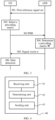
- FIG. 1 is a flowchart of a method for determining a precoding matrix indicator according to an embodiment of the present invention.
- the method in FIG. 1 is executed by user equipment (for example, UE).
- user equipment for example, UE
- 102 Select a precoding matrix based on the first reference signal set, where the precoding matrix is a function of a user equipment-specific matrix or matrix set.
- a first reference signal set is associated with a user equipment-specific matrix or matrix set
- a precoding matrix is a function of the user equipment-specific matrix or matrix set, so that user equipment can select, based on the user equipment-specific matrix or matrix set, the precoding matrix and feed back a PMI
- a set of the precoding matrix forms a user equipment-specific codebook but not a cell specific codebook or system specific codebook (cell specific codebook or system specific codebook).
- the cell specific codebook or system specific codebook is a precoding matrix set designed for all users in a cell or a system, while the user equipment-specific codebook is a subset of the cell specific codebook or system specific codebook. Therefore, in this embodiment of the present invention, CSI feedback precision can be improved without excessively increasing feedback overhead, thereby improving system performance.
- a matrix may include a multi-row multi-column matrix, or may also include a multi-row single-column vector, a single-row multi-column vector, or a scalar (single-row single-column matrix).
- the user equipment-specific matrix or matrix set is notified by the base station to the user equipment.
- the user equipment may further receive a second reference signal set sent by the base station, where the second reference signal set is associated with a matrix or matrix set. Based on the second reference signal set, the user equipment determines and sends a second index to the base station. The second index is used for indicating an antenna port or antenna port subset selected by the user equipment, or a subset of a matrix or matrix set that is associated with the antenna port or antenna port subset selected by the user equipment.
- the first reference signal set may be a subset of the second reference signal set.
- the user equipment when receiving the second reference signal set sent by the base station, may receive reference signals of the second reference signal set that are sent at different times by the base station.
- different times may be associated with a same matrix or different matrices separately, or may be associated with a same subset or different subsets of a matrix set separately.
- the matrix or matrix set associated with the second reference signal set is cell specific or system specific.
- the first reference signal set includes one or more reference signal subsets, and the reference signal subset corresponds to a co-polarized antenna port subset, or corresponds to an antenna port subset that is arranged in a same direction in an antenna port array, or corresponds to a quasi-co-location (Quasi-Co-Location, QCL for short) antenna port subset.
- the reference signal subset corresponds to a co-polarized antenna port subset, or corresponds to an antenna port subset that is arranged in a same direction in an antenna port array, or corresponds to a quasi-co-location (Quasi-Co-Location, QCL for short) antenna port subset.
- the user equipment when receiving the first reference signal set sent by the base station, may receive reference signals of the first reference signal set that are sent at different times by the base station.
- different times may be associated with a same matrix or different matrices separately, or may be associated with a same subset or different subsets of a matrix set separately.
- the precoding matrix W is a product of two matrices W 1 and W 2 .
- W W 1 W 2
- the matrix W 1 is a block diagonal matrix.
- the block diagonal matrix includes at least one block matrix, and each block matrix is a function of the user equipment-specific matrix or matrix set.
- the matrix W 2 is used to select or perform weighted combination on column vectors in the matrix W 1 , so as to form the matrix W
- columns of at least one matrix in the two matrices C and D are rotations of column vectors in a matrix in a subset of the user equipment-specific matrix or matrix set, that is, a k th column vector c k of the matrix C is:
- column vectors of the matrix C or matrix D that corresponds to the block matrix X at a different location on a diagonal in W 1 satisfy the expressions (2) to (5) does not mean that the block matrix X at a different location on a diagonal in W 1 has a same matrix C or matrix D; in contrast, the block matrix X at a different location may have a same or different matrix C or matrix D.
- a matrix in the user equipment-specific matrix or matrix set is a matrix formed by columns being discrete Fourier transformation (DFT, Discrete Fourier Transformation) vectors, or a matrix formed by column vectors of a Hadamard (Hadamard) matrix or a Householder (Householder) matrix.
- DFT discrete Fourier transformation
- Hadamard Hadamard
- Householder Householder
- the first reference signal set includes at least one reference signal subset, and the reference signal subset is associated with a set of the matrix C or the matrix D.
- the reference signal subset has a sending period longer than that of another reference signal.
- the precoding matrix W may be the following matrix: 2 M ⁇ 1 2 1 e j ⁇ ⁇ e j M ⁇ 1 ⁇ e j ⁇ e j ⁇ + ⁇ ⁇ e j ⁇ + M ⁇ 1 ⁇ T or, 4 M ⁇ 1 2 1 e j ⁇ ⁇ e j M ⁇ 1 ⁇ e j ⁇ e j ⁇ + ⁇ ⁇ e j ⁇ + M ⁇ 1 ⁇ T e j ⁇ 1 e j ⁇ ⁇ e j M ⁇ 1 ⁇ e j ⁇ e j ⁇ + M ⁇ 1 ⁇ T or, 2 NM ⁇ 1 2 1 e j ⁇ ⁇ e j M ⁇ 1 ⁇ T e j ⁇ 1 e j ⁇ ⁇ e j M ⁇ 1 ⁇ T ⁇ e j N ⁇ 1 ⁇ 1 e j ⁇ ⁇ ⁇ T or, 4 M ⁇ 1 2 1 e j ⁇ ⁇
- M is a positive integer; for example, a value of M may be 1, 2, 4, 6, 8, 16, 32, 64, and so on.
- N is a positive integer; for example, a value of N may be 1, 2, 4, 6, 8, 16, 32, 64, and so on.
- the precoding matrix W may be the following matrix: 4 NM ⁇ 1 2 1 e j ⁇ ⁇ e j M ⁇ 1 ⁇ T 1 e j ⁇ ⁇ e j M ⁇ 1 ⁇ T e j ⁇ 1 e j ⁇ ⁇ e j M ⁇ 1 ⁇ T e j ⁇ 1 e j ⁇ ⁇ e j M ⁇ 1 ⁇ T ⁇ ⁇ e j N ⁇ 1 ⁇ 1 e j ⁇ ⁇ e j M ⁇ 1 ⁇ T e j N ⁇ 1 ⁇ 1 e j ⁇ ⁇ e j M ⁇ 1 ⁇ T 1 e j ⁇ ⁇ e j M ⁇ 1 ⁇ T 1 e j ⁇ ⁇ e j M ⁇ 1 ⁇ T ⁇ 1 e j ⁇ ⁇ e j M ⁇ 1 ⁇ T ⁇ 1 e j ⁇ 1 ⁇ T e j ⁇ 1 e j ⁇ 1 e j ⁇
- M is a positive integer; for example, a value of M may be 1, 2, 4, 6, 8, 16, 32, 64, and so on.
- N is a positive integer; for example, a value of N may be 1, 2, 4, 6, 8, 16, 32, 64, and so on.
- the precoding matrix W may match an actually deployed antenna configuration; because granularity of a value of ⁇ is ⁇ /16, more precise space quantization can be implemented, and feedback precision of CSI can be improved; besides, two columns of the precoding matrix W are orthogonal to each other, and interference between layers can be reduced.
- FIG. 2 is a flowchart of a method for determining a precoding matrix indicator according to another embodiment of the present invention.
- the method in FIG. 2 is executed by a base station (for example, eNB).
- a base station for example, eNB
- 201 Send a first reference signal set to user equipment, where the first reference signal set is associated with a user equipment-specific (UE specific) matrix or matrix set.
- UE specific user equipment-specific
- 202 Receive a precoding matrix indicator PMI sent by the user equipment, where the PMI is used for indicating a precoding matrix that is selected based on the first reference signal by the user equipment, and the precoding matrix is a function of the user equipment-specific matrix or matrix set.
- a first reference signal set is associated with a subset of a user equipment-specific matrix or matrix set
- a precoding matrix is a function of the user equipment-specific matrix or matrix set, so that user equipment can select, based on the subset of the matrix or matrix set, the precoding matrix and feed back a PMI
- a set of the precoding matrix forms a user equipment-specific codebook but not a cell specific codebook or system specific codebook.
- the cell specific codebook or system specific codebook is a precoding matrix set designed for all users in a cell or a system
- the user equipment-specific codebook is a subset of the cell specific codebook or system specific codebook. Therefore, in this embodiment of the present invention, CSI feedback precision can be improved without excessively increasing feedback overhead, thereby improving system performance.
- the precoding matrix may also be obtained according to the received PMI.
- the user equipment-specific matrix or matrix set is notified by the base station to the user equipment.
- the base station may further send a second reference signal set to the user equipment, where the second reference signal set is associated with a matrix or matrix set. Then, the base station receives a second index that is determined based on the second reference signal set by the user equipment. The second index is used for indicating an antenna port or antenna port subset selected by the user equipment, or a matrix or matrix set that is associated with the antenna port or antenna port subset selected by the user equipment.
- the first reference signal set is a subset of the second reference signal set.
- the base station when sending the second reference signal set to the user equipment, may send reference signals of the second reference signal set to the user equipment at different times.
- the matrix or matrix set associated with the second reference signal set is cell specific or system specific.
- the base station may further measure an uplink physical channel or an uplink physical signal, to obtain channel estimation of the user equipment according to channel reciprocity. Based on a predefined criterion, the first reference signal and the user equipment-specific matrix or matrix set are selected for a user.
- the uplink physical channel may be a physical uplink control channel (Physical Uplink Control Channel, PUCCH for short) or a physical uplink shared channel (Physical Uplink Shared Channel, PUSCH for short); the physical signal may be a sounding reference signal (Sounding Reference Signal, SRS for short) or another uplink demodulation reference signal (DeModulation Reference signal, DMRS for short).
- the first reference signal set may include one or more reference signal subsets.
- the reference signal subset corresponds to a co-polarized antenna port subset, or corresponds to an antenna port subset that is arranged in a same direction in an antenna port array, or corresponds to a quasi-co-location antenna port subset.
- the base station may send subsets of the first reference signal set to the user equipment at different times.
- different times may be associated with a same matrix or different matrices separately, or may be associated with a same subset or different subsets of a matrix set separately.
- the matrix W 2 is used to select or perform weighted combination on column vectors in the matrix W 1 , so as to form the matrix W
- columns of at least one matrix in the two matrices C and D are rotations of column vectors in a matrix in the user equipment-specific matrix or matrix set, that is, a k th column vector c k of the matrix C is shown in the expression (2) or (3); or, an 1 th column vector d l of the matrix D is shown in the expression (4) or (5), where Nv, N H , N C , and N D are positive integers, a m is an m th column vector of a matrix A , and the matrix A is a matrix in the user equipment-specific matrix or matrix set.
- column vectors of the matrix C or matrix D that corresponds to the block matrix X at a different location on a diagonal in W 1 satisfy the expressions (2) to (5) does not mean that the block matrix X at a different location on a diagonal in W 1 has a same matrix C or matrix D; in contrast, the block matrix X at a different location may have a same or different matrix C or matrix D.
- a matrix in the user equipment-specific matrix or matrix set is a matrix formed by columns being DFT vectors, or a matrix formed by column vectors of a Hadamard matrix or a Householder matrix.
- the DFT vector a l is shown in the expression (6), where N C ⁇ N or N D ⁇ N.
- the first reference signal set includes at least one reference signal subset, and the reference signal subset is associated with a set of the matrix C or the matrix D.
- the reference signal subset has a sending period longer than that of another reference signal.
- the precoding matrix W may be the following matrix: 2 M ⁇ 1 2 1 e j ⁇ ⁇ e j M ⁇ 1 ⁇ e j ⁇ e j ⁇ + ⁇ ⁇ e j ⁇ + M ⁇ 1 ⁇ T or, 4 M ⁇ 1 2 1 e j ⁇ ⁇ e j M ⁇ 1 ⁇ e j ⁇ e j ⁇ + ⁇ ⁇ e j ⁇ + M ⁇ 1 ⁇ T e j ⁇ 1 e j ⁇ ⁇ e j M ⁇ 1 ⁇ e j ⁇ e j ⁇ + M ⁇ 1 ⁇ T or, 2 NM ⁇ 1 2 1 e j ⁇ ⁇ e j M ⁇ 1 ⁇ T e j ⁇ 1 e j ⁇ ⁇ e j M ⁇ 1 ⁇ T ⁇ e j N ⁇ 1 ⁇ 1 e j ⁇ ⁇ ⁇ T or, 4 M ⁇ 1 2 1 e j ⁇ ⁇
- M is a positive integer; for example, a value of M may be 1, 2, 4, 6, 8, 16, 32, 64, and so on.
- N is a positive integer; for example, a value of N may be 1, 2, 4, 6, 8, 16, 32, 64, and so on.
- the precoding matrix W may be the following matrix: 4 NM ⁇ 1 2 1 e j ⁇ ⁇ e j M ⁇ 1 ⁇ T 1 e j ⁇ ⁇ e j M ⁇ 1 ⁇ T e j ⁇ 1 e j ⁇ ⁇ e j M ⁇ 1 ⁇ T e j ⁇ 1 e j ⁇ ⁇ e j M ⁇ 1 ⁇ T ⁇ ⁇ e j N ⁇ 1 ⁇ 1 e j ⁇ ⁇ e j M ⁇ 1 ⁇ T e j N ⁇ 1 ⁇ 1 e j ⁇ ⁇ e j M ⁇ 1 ⁇ T 1 e j ⁇ ⁇ e j M ⁇ 1 ⁇ T 1 e j ⁇ ⁇ e j M ⁇ 1 ⁇ T ⁇ 1 e j ⁇ ⁇ e j M ⁇ 1 ⁇ T ⁇ 1 e j ⁇ 1 ⁇ T e j ⁇ 1 e j ⁇ 1 e j ⁇
- M is a positive integer; for example, a value of M may be 1, 2, 4, 6, 8, 16, 32, 64, and so on.
- N is a positive integer; for example, a value of N may be 1, 2, 4, 6, 8, 16, 32, 64, and so on.
- the precoding matrix W may match an actually deployed antenna configuration; because granularity of a value of ⁇ is ⁇ /16, more precise space quantization can be implemented, and feedback precision of CSI can be improved; besides, two columns of the precoding matrix W are orthogonal to each other, and interference between layers can be reduced.
- an eNB is used as an example of a base station
- UE is used as an example of user equipment, but the embodiments of the present invention are not limited thereto, and may also be applied to other communications systems.
- FIG. 3 is a schematic flowchart of a multi-antenna transmission method according to an embodiment of the present invention.
- UE receives a first reference signal set, where the first reference signal set is associated with a user equipment-specific (UE-specific) matrix or matrix set.
- UE-specific user equipment-specific
- the first reference signal set received by the UE is notified by an eNB by using higher layer signaling, or is dynamically notified by an eNB by using a downlink control channel.
- the reference signal may be a cell specific reference signal (CRS, Cell specific RS), or a demodulation reference signal (DMRS, DeModulation RS), or a channel state information reference signal (CSI-RS, channel state information RS).
- CRS cell specific reference signal
- DMRS demodulation reference signal
- CSI-RS channel state information reference signal
- the reference signal may correspond to a physical antenna, or may also correspond to a virtual antenna, where the virtual antenna is a weighted combination of multiple physical antennas.
- the first reference signal set may include one or more reference signal subsets.
- the first reference signal set received by the UE is P, which includes in total eight reference signals, namely, p1, p2, p3, ..., p7, and p8.
- the first reference signal set may include one reference signal subset.
- the reference signal subset is the same as the first reference signal set, that is, the eight reference signals p1, p2, ..., and s8 in P.
- the first reference signal set may include multiple reference signal subsets.
- the reference signal subset included in the first reference signal set may correspond to a co-polarized antenna port subset.
- the reference signal subset included in the first reference signal set may correspond to a port subset that is arranged in a same direction in an antenna port array.
- the subset P2 ⁇ p5, p 6, p7, p8 ⁇ of the first reference signal set corresponds to an antenna port subset of a row in a horizontal direction in the antenna port array.
- the reference signal subset included in the first reference signal set may correspond to a quasi-co-location antenna port subset.
- the subset P1 ⁇ p5, p 6, p7, p8 ⁇ of the first reference signal set corresponds to an antenna port subset that is located at another quasi-co-location.
- the quasi-co-location (QCL, Quasi-Co-Location) antenna port refers to that a distance between antennas corresponding to the antenna port is within a range that uses a wavelength as a dimension.
- each of the foregoing antenna ports corresponds to a physical antenna or virtual antenna, where the virtual antenna is a weighted combination of multiple physical antennas or antenna array elements.
- reference signals in the multiple reference signal subsets included in the first reference signal set may occupy different symbol/frequency/sequence resources and be transmitted at a same subframe, or may occupy a same symbol/frequency/sequence resource and be transmitted at different subframes.
- the foregoing division of the reference signal subset may further reduce complexity of implementation.
- the first reference signal set is associated with a subset of a user equipment-specific (UE-specific) matrix or matrix set; or each reference signal in the first reference signal set may be associated with a subset of a user equipment-specific (UE-specific) matrix or matrix set.
- the reference signal set notified by the eNB is S, which includes in total eight reference signals, namely s1, s2, s3, ..., s7, and s8.
- the foregoing reference signals are associated with matrices w1, w2, ..., and w8 separately, or are associated with ⁇ w1,w2 ⁇ , ⁇ w2,w3 ⁇ , ..., ⁇ w7,w8 ⁇ , and ⁇ w8,w1 ⁇ separately.
- the first reference signal set is associated with a subset of a matrix or matrix set, or a reference signal subset of the first reference signal set may be associated with a subset of a user equipment-specific matrix or matrix set.
- the reference signal set notified by the eNB is S, which includes in total eight reference signals, namely s1, s2, s3, ..., s7, and s8.
- a reference signal subset ⁇ s1, s2, s3, s4 ⁇ is associated with a matrix p1 or a matrix subset ⁇ p1, ..., pm ⁇
- a reference signal subset ⁇ s5, s6, s7, s8 ⁇ is associated with a matrix w1 or a matrix subset ⁇ w1, ..., wn ⁇ , where m and n are positive integers.
- reference signal subsets ⁇ s1, s2 ⁇ , ⁇ s3, s4 ⁇ , ..., and ⁇ s7, s8 ⁇ are associated with matrices w1, w2, w3, and w4 respectively.
- reference signal subsets ⁇ s1, s2 ⁇ , ⁇ s3, s4 ⁇ , ..., and ⁇ s7, s8 ⁇ are associated with matrices ⁇ w1, w2 ⁇ , ⁇ w3, w4 ⁇ , ..., and ⁇ w7, w8 ⁇ respectively.
- the matrix herein includes a vector.
- an association or a correspondence between the first reference signal set and a user equipment-specific matrix or matrix set may be notified by using signaling. For example, it is notified by using higher layer signaling, for example, radio resource control (RRC, Radio Resource Control) signaling, that the reference signal subset ⁇ s1, s2, s3, s4 ⁇ is associated with a matrix p1 or a matrix subset ⁇ p1, ..., pm ⁇ , and the reference signal subset ⁇ s5, s6, s7, s8 ⁇ is associated with a matrix w1 or a matrix subset ⁇ w1, ..., wn ⁇ .
- RRC Radio Resource Control
- the association or correspondence between the first reference signal set and a user equipment-specific matrix or matrix set is dynamically notified by using downlink control information (DCI, Downlink Control information).
- DCI Downlink Control information
- multiple candidate association relationships are notified by using higher layer signaling, for example RRC signaling, and one of the candidate association relationships is further dynamically notified by using DCI.
- each matrix subset in the signaling may be represented by a bitmap (bitmap).
- the RRC signaling may be UE-specific signaling, for example, dedicated physical signaling.
- the first reference signal set and indication information of the UE-specific matrix or matrix set may be sent in same RRC dedicated signaling.
- an association relationship or mapping between the first reference signal set and a user equipment-specific matrix or matrix set may also be predefined.
- the reference signal subset ⁇ s1, s2, s3, s4 ⁇ is associated with a matrix p1 or a matrix subset ⁇ p1, ..., pm ⁇
- the reference signal subset ⁇ s5, s6, s7, s8 ⁇ is associated with a matrix w1 or a matrix subset ⁇ w1, ..., wn ⁇ .
- the first reference signal set is associated with a subset of a matrix or matrix set, or the first reference signal set may be associated with a matrix or matrix set, where a subset of the matrix or matrix set is notified by using signaling or is predefined.
- a matrix or matrix subset is notified by using higher layer signaling, for example, RRC signaling, or is dynamically notified by using DCI; or, a matrix set is notified by using higher layer signaling, for example, RRC signaling, and one matrix subset in the matrix set is further dynamically notified by using DCI.
- the matrix in the user equipment-specific (UE specific) matrix or the matrix set may also use a matrix in another form, for example, a Householder matrix, or a precoding matrix in an LTE R8 4-antenna or LTE R10 8-antenna codebook.
- vectors c k and d k in the expressions (24) to (27) may have granularity finer than that of a l and b l respectively, that is, N C ⁇ N or N D ⁇ N ′
- a set formed by the foregoing vector or matrix A or B or Y or W is C A or C B or C Y or C W , and may be further divided into multiple subsets (the subset may include only one element), and each subset may be associated with or have a mapping relationship with a user equipment identifier.
- a subset C A 1 in C A is associated with or is mapped to a user equipment identifier ID 1
- another subset C A 2 in C A is associated with or is mapped to a user equipment identifier ID 2
- the subsets C A 1 and C A 2 may intersect, or may not intersect.
- An association or a mapping relationship between the foregoing vector or matrix or subset of the matrix with the user equipment identifier may be predefined, or may also be notified by the eNB to the UE, for example, notified by using higher layer signaling, for example, RRC signaling or a downlink control channel. Each subset may include only one element.
- the reference signal set may be associated with a user equipment identifier.
- the reference signal set notified by the eNB is S, which includes in total eight reference signals, namely s1, s2, s3, ..., s7, and s8.
- the foregoing reference signal is associated with a user equipment identifier ID 0 ; or the reference signal set received by the UE may be divided into two or more subsets, and the subsets are associated with specific user equipment identifiers separately.
- the reference signal set received by the UE may be divided into two subsets, one including reference signals s1, s2, s3, and s4 and the other s5, s6, s7, and s8, and then s1, s2, s3, and s4 are associated with identifiers user equipment ID 1 and ID 2 .
- An association or a mapping relationship between the reference signal set and a user equipment identifier may be predefined, or may also be notified by the eNB.
- the user equipment identifier is not necessarily a UE ID in a specific communications protocol, for example, LTE, but may also be a specific parameter that is used to distinguish a user equipment attribute, for example, an index or an offset in a user group or a UE group, or simply an index or an offset used in a same user group or UE group.
- the offset or index facilitates implementation of distinguishing of attributes related to different beams among user equipments or user groups.
- reference signals in the reference signal set may be sent at different times, for example, different subframes, and the different times may be associated with or mapped to different vectors/matrices or different subsets of matrix sets.
- the different vectors/matrices or different subsets of matrix sets that the reference signals are associated with or mapped to at different times may be predefined, or may also be notified by the eNB, for example, notified by using RRC signaling.
- the UE selects a precoding matrix based on the first reference signal set, where the precoding matrix is a function of the user equipment-specific matrix or matrix set.
- the precoding matrix is a function of the user equipment-specific matrix or matrix set includes that:
- At least one of the matrix A or the matrix B is a matrix in the user equipment-specific matrix or matrix set.
- the block matrices X 1 and X 2 each have 4 columns
- the matrix W 2 may be represented as: W 2 ⁇ 1 2 Y Y , 1 2 Y j Y , 1 2 Y ⁇ Y , 1 2 Y ⁇ j Y Y ⁇ e ⁇ 1 e ⁇ 2 e ⁇ 3 e ⁇ 4 or, W 2 ⁇ 1 2 Y 1 Y 2 Y 1 ⁇ Y 2 , 1 2 Y 1 Y 2 j Y 1 ⁇ j Y 2 Y 1 Y 2 ⁇ e ⁇ 1 , e ⁇ 2 e ⁇ 2 , e ⁇ 3 e ⁇ 3 , e ⁇ 4 e ⁇ 4 , e ⁇ 1 e ⁇ 2 e ⁇ 2 e ⁇ 3 , e ⁇ 1 e ⁇ 4 , e ⁇ 2 e ⁇ 2 ⁇ 4
- ⁇ 2 e ⁇ 4 where è n ,
- the block matrices X 1 and X 2 each have 8 columns
- the matrix W 2 may be represented as: W 2 ⁇ 1 2 Y Y , 1 2 Y j Y , 1 2 Y ⁇ Y , 1 2 Y ⁇ j Y Y ⁇ e 1 e 2 e 3 e 4 e 5 e 6 e 7 e 8 or, W 2 ⁇ 1 2 Y 1 Y 2 Y 1 ⁇ Y 2 , 1 2 Y 1 Y 2 j Y 1 ⁇ j Y 2 Y 1 Y 2 ⁇ e 1 e 1 , e 2 e 2 , e 3 e 3 , e 4 e 4 , e 1 e 2 e 2 e 3 , e 1 e 4 , e 2 e 4
- W 1 x
- X is a function of the matrix A or B.
- vectors c k and d k in the expressions (47) to (50) may have granularity finer than that of a l and b l , that is, N D ⁇ N or N D ⁇ N
- the UE sends a precoding matrix indicator PMI to the base station, where the PMI corresponds to the selected precoding matrix.
- the precoding matrix indicator PMI may include one or more indexes.
- the precoding matrix indicator PMI may include one index.
- the index indicates directly the precoding matrix W .
- the precoding matrix indicator PMI may also be two indexes, for example, i 1 and i 2 .
- W 1 and W 2 in the expression (29) are indicated by using i 1 and i 2 respectively, so that i 1 and i 2 indicate the precoding matrix W
- the index i 1 may be reported based on a subset of W 1 .
- a universal set of W 1 is Q, and subsets of the set Q are Q 0 , ..., and Q .3 separately.
- the index i 1 is used to indicate a matrix W 1 in a subset Q k , where Q k may be one subset in Q 0 , Q 1 ..., and Q 3 .
- Qk may be predefined, or may be determined and reported by the UE, or may also be notified by the eNB to the UE.
- the subsets Q0, ..., and Q3 may not intersect with each other, that is, an intersection set of the subsets is an empty set; or the subsets Q0, ..., and Q3 may intersect with each other, that is, an intersection set of the subsets is not an empty set.
- i 3 , i 4 , and i 5 there may also be three indexes reported by the UE and used to indicate the precoding matrix, for example, i 3 , i 4 , and i 5 .
- X 1 and X 2 in the expression (30) are implicitly indicated by using i 3 and i 4 respectively, and W 2 is implicitly indicated by using i 5 . Therefore, i 3 , i 4 , and i 5 indicate the precoding matrix W
- the index i 3 may be reported based on a subset of X 1 .
- a universal set of X 1 is R, and subsets of the set R are R 0 , ..., and R 7 separately.
- the index i 3 is used to indicate a matrix X 1 in a subset R k .
- R k may be one subset in R 0 , R 1 ..., and R 7 .
- R k may be predefined, or may be determined and reported by the UE, or may also be notified by the eNB to the UE.
- the subsets R 0 , ..., and R 7 may not intersect with each other, that is, an intersection set of the subsets is an empty set; or the subsets R 0 , ..., and R 7 may intersect with each other, that is, an intersection set of the subsets is not an empty set; similarly, i 4 and i 5 may be reported based on subsets of X 2 and W 2 respectively.
- the subsets of X 2 and W 2 may be predefined, or may be determined and reported by the UE, or may also be notified by the eNB to the UE.
- indexes reported by the UE and used to indicate the precoding matrix may also be other three indexes, for example, i6, i7 and i8.
- the index i 6 may be reported based on a subset of C i .
- a universal set of C i is O, and subsets of the set O are O 0 , ..., and O 7 separately.
- the index i 6 is used to indicate a matrix C i in a subset O k .
- O k may be one subset in O 0 , O 1 ..., and O 7 .
- O k may be predefined, or may also be determined and reported by the UE, or may also be notified by the eNB to the UE.
- the subsets O 0 , ..., and O 7 may not intersect with each other, that is, an intersection set of the subsets is an empty set; or the subsets O 0 , ..., O 7 may intersect with each other, that is, an intersection set of the subsets is not an empty set; similarly, i 7 and i 8 may be reported based on subsets of D i and W 2 respectively.
- the subsets of D i and W 2 may be predefined, or may be determined and reported by the UE, or may also be notified by the eNB to the UE.
- indexes reported by the UE and used to indicate the precoding matrix may also be four indexes, for example, i 9 , i 10 , i 11 , and i 12 .
- i 9 , i10, i 11 , and i 12 may be reported based on subsets of C 1 , C 2 , D i , and W 2 respectively.
- the subsets of C 1 , C 2 , D i , and W 2 may be predefined, or may be determined and reported by the UE, or may also be notified by the eNB to the UE.
- the index value may be calculated based on one reference signal subset.
- the foregoing index value n is calculated based on the reference signal subset P in step 301, or the index values i 1 and i 2 , or i 3 , i 4 , and i 5 , or i 6 , i 7 , and i 8 , or i 9 , i 10 , i 11 , and i 12 are calculated based on the reference signal subset P in step 1.
- the index value may be calculated in combination based on multiple reference signal subsets.
- the index value n is calculated based on the reference signal subsets P1 and P2 in step 301, or the index values i 1 and i 2 , or i 3 , i 4 , and i 5 , or i 6 , i 7 , and i 8 , or i 9 , i 10 , i 11 , and i 12 are calculated based on the reference signal subsets P1 and P2 in step 1.
- the index values are calculated separately based on multiple reference signal subsets.
- the index value i 3 is calculated based on the reference signal subset P1 in step 301
- the index values i 4 and i 5 are calculated based on the reference signal subset P2 in step 301.
- the index value i 6 is calculated based on the reference signal subset P1 in step 301
- the index values i 7 and i 8 are calculated based on the reference signal subset P2 in step 301.
- the index values i 9 and i 10 are calculated based on the reference signal subset P1 in step 301
- the index values i 11 and i 12 are calculated based on the reference signal subset P2 in step 301.
- the UE may determine the foregoing one or more indexes according to a measured channel state based on a preset criterion, and the preset criterion may be a maximum throughput criterion or a maximum capacity criterion. After the one or more indexes are obtained, the UE may feed back the indexes to the eNB by using a PUCCH or a PUSCH.
- the precoding matrix indicator PMI may include one or more indexes, and the UE may report the indexes to the eNB through different subframes by using a physical uplink control channel (PUCCH, Physical Uplink Control Channel).
- PUCCH Physical Uplink Control Channel
- the foregoing multiple different indexes may be reported to the eNB through different subframes for different subbands on a frequency domain.
- matrices corresponding to the indexes may be single matrices, so that corresponding indexes do not need to be fed back.
- the single matrix may be a predefined matrix, or may also be notified by a base station by using signaling, or may also be obtained implicitly according to other parameters.
- W 2 is fixedly selected as the matrix shown in the expression (51), so that an index corresponding to W 2 does not need to be fed back. In this case, W 2 is obtained implicitly according to a rank r of the precoding matrix.
- the base station obtains the precoding matrix W based on the received precoding matrix indicator PMI.
- the base station uses the precoding matrix W to transmit a signal vector S. Specifically, after precoding, a transmitted signal vector is W s .
- a first reference signal set is associated with or corresponds to a user equipment-specific matrix or matrix set
- a precoding matrix is a function of the user equipment-specific matrix or matrix set. Therefore, user equipment can select, based on the user equipment-specific matrix or matrix set, the precoding matrix and feed back a PMI, and a set of the precoding matrix forms a user equipment-specific codebook but not a cell specific codebook or system specific codebook.
- the cell specific codebook or system specific codebook is a precoding matrix set designed for all users in a cell or a system, while the user equipment-specific codebook is a subset of the cell specific codebook or system specific codebook. Therefore, in this embodiment of the present invention, CSI feedback precision can be improved without excessively increasing feedback overhead, thereby improving system performance.
- one or more indexes are fed back based on a subset to indicate a precoding matrix, and correlation between time/frequency domain/space of a channel is fully utilized, so that feedback overhead is greatly reduced.
- step 301 of receiving a first reference signal set sent by a base station the following optional steps may further be included:
- the first reference signal set is a subset of the second reference signal set, or the second reference signal set is a superset of the first reference signal set.
- the first reference signal set is a subset of the second reference signal set (or equivalently, the second reference signal set is a superset of the first reference signal set) includes that: the second reference signal set is the same as the first reference signal set; or the second reference signal set is a proper subset of the first reference signal set, and in this case, a quantity of reference signals included in the second reference signal set is less than a quantity of reference signals included in the first reference signal set.
- the base station uses a reference signal or a reference signal subset corresponding to the antenna port or antenna port subset, initially selected by the UE and indicated by the second index that is reported by the UE, in the second reference signal set, as the first reference signal set; or the base station uses a subset of a matrix or matrix set that is associated with the antenna port or antenna port subset initially selected by the UE and indicated by the second index that is reported by the UE, as a matrix or matrix set that is associated with the first reference signal set.
- the base station may refer to the second index as assistance, but the base station also may not refer to the second index.
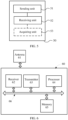
- FIG. 4 is a block diagram of user equipment according to an embodiment of the present invention.
- the user equipment 40 in FIG. 4 includes a receiving unit 41, a determining unit 42, and a sending unit 43.
- the receiving unit 41 receives a first reference signal set sent by a base station, where the first reference signal set is associated with a user equipment-specific (UE-specific) matrix or matrix set.
- the determining unit 42 selects a precoding matrix based on the first reference signal set, where the precoding matrix is a function of the user equipment-specific matrix or matrix set.
- the sending unit 43 sends a precoding matrix indicator PMI to the base station, where the PMI corresponds to the selected precoding matrix.
- a first reference signal set is associated with or corresponds to a user equipment-specific matrix or matrix set
- a precoding matrix is a function of the user equipment-specific matrix or matrix set, so that the PMI can select, based on the user equipment-specific matrix or matrix set, the precoding matrix and feed back a PMI
- a set of the precoding matrix forms a user equipment-specific codebook but not a cell specific codebook or system specific codebook.
- the cell specific codebook or system specific codebook is a precoding matrix set designed for all users in a cell or a system
- the user equipment-specific codebook is a subset of the cell specific codebook or system specific codebook. Therefore, in this embodiment of the present invention, CSI feedback precision can be improved without excessively increasing feedback overhead, thereby improving system performance.
- the receiving unit 41 is further configured to receive the user equipment-specific matrix or matrix set notified by the base station.
- the receiving unit is further configured to: before the first reference signal set is received, receive a second reference signal set sent by the base station, where the second reference signal set is associated with a matrix or matrix set; the determining unit is further configured to determine a second index based on the second reference signal set, where the second index is used for indicating an antenna port or antenna port subset selected by the user equipment, or a matrix or matrix set that is associated with the antenna port or antenna port subset selected by the user equipment; and the sending unit is further configured to send the second index to the base station.
- the first reference signal set is a subset of the second reference signal set.
- the matrix or matrix set associated with the second reference signal set is cell specific or system specific.
- the receiving unit is specifically configured to receive reference signals of the second reference signal set that are sent at different times by the base station.
- different times may be associated with a same matrix or different matrices separately, or may be associated with a same subset or different subsets of a matrix set separately.
- the first reference signal set includes one or more reference signal subsets, and the reference signal subset corresponds to a co-polarized antenna port subset, or corresponds to an antenna port subset that is arranged in a same direction in an antenna port array, or corresponds to an antenna port subset that is located at a quasi-co-location.
- the receiving unit is specifically configured to receive reference signals of the first reference signal set that are sent at different times by the base station.
- different times may be associated with a same matrix or different matrices separately, or may be associated with a same subset or different subsets of a matrix set separately.
- the matrix W 2 is used to select or perform weighted combination on column vectors in the matrix W 1 , so as to form the matrix W
- columns of at least one matrix in the two matrices C and D are rotations of column vectors in a matrix in the user equipment-specific matrix or matrix set, that is, a k th column vector c k of the matrix C is shown in the expression (2) or (3); or, an 1 th column vector d l of the matrix D is shown in the expression (4) or (5), where Nv, N H , N C , and N D are positive integers, a m is an m th column vector of a matrix A , and the matrix A is a matrix in the user equipment-specific matrix or matrix set.
- column vectors of the matrix C or matrix D that corresponds to the block matrix X at a different location on a diagonal in W 1 satisfy the expressions (2) to (5) does not mean that the block matrix X at a different location on a diagonal in W 1 has a same matrix C or matrix D; in contrast, the block matrix X at a different location may have a same or different matrix C or matrix D.
- a matrix in the user equipment-specific matrix or matrix set is a matrix formed by columns being DFT vectors, or a matrix formed by column vectors of a Hadamard matrix or a Householder matrix.
- the DFT vector a l is shown in the expression (6), where N C ⁇ N or N D ⁇ N.
- the first reference signal set includes at least one reference signal subset, and the reference signal subset is associated with a set of the matrix C or the matrix D.
- the reference signal subset has a sending period longer than that of another reference signal.
- FIG. 5 is a block diagram of a base station according to an embodiment of the present invention.
- the base station 50 in FIG. 5 includes a sending unit 51 and a receiving unit 52.
- the sending unit 51 is configured to send a first reference signal set to user equipment, where the first reference signal set is associated with a user equipment-specific (UE-specific) matrix or matrix set; and the receiving unit 52 is configured to receive a precoding matrix indicator PMI sent by the user equipment, where the PMI is used for indicating a precoding matrix that is selected based on the first reference signal by the user equipment, and the precoding matrix is a function of the user equipment-specific matrix or matrix set.
- UE-specific user equipment-specific
- a first reference signal set is associated with or corresponds to a user equipment-specific matrix or matrix set
- a precoding matrix is a function of the user equipment-specific matrix or matrix set, so that user equipment can select, based on the matrix or matrix set, the precoding matrix and feed back a PMI
- a set of the precoding matrix forms a user equipment-specific codebook but not a cell specific codebook or system specific codebook.
- the cell specific codebook or system specific codebook is a precoding matrix set designed for all users in a cell or a system, while the user equipment-specific codebook is a subset of the cell specific codebook or system specific codebook. Therefore, in this embodiment of the present invention, CSI feedback precision can be improved without excessively increasing feedback overhead, thereby improving system performance.
- the base station 50 may further include an acquiring unit 53, configured to obtain the precoding matrix according to the received PMI.
- the sending unit 51 is further configured to notify the user equipment of the user equipment-specific matrix or matrix set.
- the sending unit 51 is further configured to: before the first reference signal set is sent to the user equipment, send a second reference signal set to the user equipment, where the second reference signal set is associated with a matrix or matrix set; and the receiving unit is further configured to receive a second index that is determined based on the second reference signal set by the user equipment, where the second index is used for indicating an antenna port or antenna port subset selected by the user equipment, or a matrix or matrix set that is associated with the antenna port or antenna port subset selected by the user equipment.
- the first reference signal set is a subset of the second reference signal set.
- the matrix or matrix set associated with the second reference signal set is cell specific or system specific.
- the acquiring unit 53 is further configured to measure an uplink physical channel or an uplink physical signal, and obtain channel estimation of the user equipment according to channel reciporocity. Based on a predefined criterion, the first reference signal and the user equipment-specific matrix or matrix set are selected for a user.
- the uplink physical channel may be a physical uplink control channel (Physical Uplink Control Channel, PUCCH for short) or a physical uplink shared channel (Physical Uplink Shared Channel, PUSCH for short); the physical signal may be a sounding reference signal (Sounding Reference Signal, SRS for short) or another uplink demodulation reference signal (DeModulation Reference signal, DMRS for short).
- the sending unit is specifically configured to send reference signals of the second reference signal set to the user equipment at different times.
- different times may be associated with a same matrix or different matrices separately, or may be associated with a same subset or different subsets of a matrix set separately.
- the first reference signal set includes one or more reference signal subsets, and the reference signal subset corresponds to a co-polarized antenna port subset, or corresponds to an antenna port subset that is arranged in a same direction in an antenna port array, or corresponds to a quasi-co-location antenna port subset.
- the sending unit is specifically configured to send reference signals of the first reference signal set to the user equipment at different times.
- different times may be associated with a same matrix or different matrices separately, or may be associated with a same subset or different subsets of a matrix set separately.
- the matrix W 2 is used to select or perform weighted combination on column vectors in the matrix W 1 , so as to form the matrix W.
- columns of at least one matrix in the two matrices C and D are rotations of column vectors in a matrix in the user equipment-specific matrix or matrix set, that is, a k th column vector c k of the matrix C is shown in the expression (2) or (3); or, an 1 th column vector d / of the matrix D is shown in the expression (4) or (5), where Nv, N H , N C , and N D are positive integers, a m is an m th column vector of a matrix A , and the matrix A is a matrix in the user equipment-specific matrix or matrix set.
- column vectors of the matrix C or matrix D that corresponds to the block matrix X at a different location on a diagonal in W 1 satisfy the expressions (2) to (5) does not mean that the block matrix X at a different location on a diagonal in W 1 has a same matrix C or matrix D; in contrast, the block matrix X at a different location may have a same or different matrix C or matrix D.
- a matrix in the user equipment-specific matrix or matrix set is a matrix formed by columns being DFT vectors, or a matrix formed by column vectors of a Hadamard matrix or a Householder matrix.
- the DFT vector a l is shown in the expression (6), where N C ⁇ N or N D ⁇ N.
- the first reference signal set includes at least one reference signal subset, and the reference signal subset is associated with a set of the matrix C or the matrix D.
- the reference signal subset has a sending period longer than that of another reference signal.
- FIG. 6 is a block diagram of user equipment according to another embodiment of the present invention.
- the user equipment 60 in FIG. 6 includes a receiver 62, a transmitter 63, a processor 64, and a memory 65.
- the receiver 62 is configured to receive a first reference signal set sent by a base station, where the first reference signal set is associated with a user equipment-specific (UE specific) matrix or matrix set.
- UE specific user equipment-specific
- the memory 65 stores an instruction that enables the processor 64 to perform the following operation: selecting a precoding matrix based on the first reference signal set, where the precoding matrix is a function of the user equipment-specific matrix or matrix set.
- the transmitter 63 is configured to send a precoding matrix indicator PMI to the base station, where the PMI corresponds to the selected precoding matrix.
- a first reference signal set is associated with or corresponds to a user equipment-specific matrix or matrix set
- a precoding matrix is a function of the user equipment-specific matrix or matrix set, so that the user equipment can select, based on the user equipment-specific matrix or matrix set, the precoding matrix and feed back a PMI
- a set of the precoding matrix forms a user equipment-specific codebook but not a cell specific codebook or system specific codebook.
- the cell specific codebook or system specific codebook is a precoding matrix set designed for all users in a cell or a system
- the user equipment-specific codebook is a subset of the cell specific codebook or system specific codebook. Therefore, in this embodiment of the present invention, CSI feedback precision can be improved without excessively increasing feedback overhead, thereby improving system performance.
- the receiver 62, the transmitter 63, the processor 64, and the memory 65 may be integrated into a processing chip. Alternatively, as shown in FIG. 6 , the receiver 62, the transmitter 63, the processor 64, and the memory 65 are connected by using a bus 66.
- the user equipment 60 may further include an antenna 61.
- the processor 64 may further control an operation of the user equipment 60, and the processor 64 may further be referred to as a CPU (Central Processing Unit, central processing unit).
- the memory 65 may include a read only memory and a random access memory, and provides an instruction and data to the processor 64. A part of the memory 65 may further include a non-volatile random access memory. Components of the user equipment 60 are coupled together by using a bus system 66.
- the bus system 66 may include, in addition to a data bus, a power bus, a control bus, a status signal bus, and the like. However, for the purpose of clear description, all buses are marked as the bus system 66 in the figure.
- the receiver 62 is further configured to receive the user equipment-specific matrix or matrix set notified by the base station.
- the receiver 62 is further configured to: before the first reference signal set is received, receive a second reference signal set sent by the base station, where the second reference signal set is associated with a matrix or matrix set; the memory 65 further stores an instruction that enables the processor 64 to perform the following operation: determining a second index based on the second reference signal set, where the second index is used for indicating an antenna port or antenna port subset selected by the user equipment, or a matrix or matrix set that is associated with the antenna port or antenna port subset selected by the user equipment 60; and the transmitter 63 is further configured to send the second index to the base station.
- the first reference signal set is a subset of the second reference signal set.
- the receiver 62 is specifically configured to receive reference signals of the second reference signal set that are sent at different times by the base station.
- different times may be associated with a same matrix or different matrices separately, or may be associated with a same subset or different subsets of a matrix set separately.
- the first reference signal set includes one or more reference signal subsets, and the reference signal subset corresponds to a co-polarized antenna port subset, or corresponds to an antenna port subset that is arranged in a same direction in an antenna port array, or corresponds to an antenna port subset that is located at a quasi-co-location.
- the receiver 62 is specifically configured to receive reference signals of the first reference signal set that are sent at different times by the base station.
- different times may be associated with a same matrix or different matrices separately, or may be associated with a same subset or different subsets of a matrix set separately.
- the matrix W 2 is used to select or perform weighted combination on column vectors in the matrix W 1 , so as to form the matrix W.
- columns of at least one matrix in the two matrices C and D are rotations of column vectors in a matrix in the user equipment-specific matrix or matrix set, that is, a k th column vector c k of the matrix C is shown in the expression (2) or (3); or, an 1 th column vector d / of the matrix D is shown in the expression (4) or (5), where Nv, N H , N C , and N D are positive integers, a m is an m th column vector of a matrix A , and the matrix A is a matrix in the user equipment-specific matrix or matrix set.
- column vectors of the matrix C or matrix D that corresponds to the block matrix X at a different location on a diagonal in W 1 satisfy the expressions (2) to (5) does not mean that the block matrix X at a different location on a diagonal in W 1 has a same matrix C or matrix D; in contrast, the block matrix X at a different location may have a same or different matrix C or matrix D.
- a matrix in a subset of the user equipment-specific matrix or matrix set is a matrix formed by columns being DFT vectors, or a matrix formed by column vectors of a Hadamard matrix or a Householder matrix.
- the DFT vector a l is shown in the expression (6), where N C ⁇ N or N D ⁇ N.
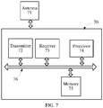
- FIG. 7 is a block diagram of a base station according to another embodiment of the present invention.
- the base station 70 in FIG. 7 includes a transmitter 72, a receiver 73, a processor 74, and a memory 75.
- the transmitter 72 is configured to send a first reference signal set to user equipment, where the first reference signal set is associated with a user equipment-specific (UE specific) matrix or matrix set.
- UE specific user equipment-specific
- the receiver 73 is configured to receive a precoding matrix indicator PMI sent by the user equipment, where the PMI is used for indicating a precoding matrix that is selected based on the first reference signal by the user equipment, and the precoding matrix is a function of the user equipment-specific matrix or matrix set.
- the memory 75 may store an instruction that enables the processor 74 to perform the following operation: obtaining the precoding matrix according to the received PMI.
- a first reference signal set is associated with or corresponds to a user equipment-specific matrix or matrix set
- a precoding matrix is a function of the user equipment-specific matrix or matrix set, so that user equipment can select, based on the user equipment-specific matrix or matrix set, the precoding matrix and feed back a PMI
- a set of the precoding matrix forms a user equipment-specific codebook but not a cell specific codebook or system specific codebook.
- the cell specific codebook or system specific codebook is a precoding matrix set designed for all users in a cell or a system
- the user equipment-specific codebook is a subset of the cell specific codebook or system specific codebook. Therefore, in this embodiment of the present invention, CSI feedback precision can be improved without excessively increasing feedback overhead, thereby improving system performance.
- the transmitter 72, the receiver 73, the processor 74, and the memory 75 may be integrated into a processing chip. Alternatively, as shown in FIG. 6 , the transmitter 72, the receiver 73, the processor 74, and the memory 75 are connected by using a bus 76.
- the base station 70 may further include an antenna 71.
- the processor 74 may further control an operation of the base station 70, and the processor 74 may further be referred to as a CPU (Central Processing Unit, central processing unit).
- the memory 75 may include a read only memory and a random access memory, and provides an instruction and data to the processor 74. A part of the memory 75 may further include a non-volatile random access memory.
- Components of the user equipment 70 are coupled together by using a bus system 76.
- the bus system 76 may include, in addition to a data bus, a power bus, a control bus, a status signal bus, and the like. However, for the purpose of clear description, all buses are marked as the bus system 76 in the figure.
- the transmitter 72 is further configured to notify the user equipment of the user equipment-specific matrix or matrix set.
- the transmitter 72 is further configured to: before the first reference signal set is sent to the user equipment, send a second reference signal set to the user equipment, where the second reference signal set is associated with a matrix or matrix set; and the receiver 73 is further configured to receive a second index that is determined based on the second reference signal set by the user equipment, where the second index is used for indicating an antenna port or antenna port subset selected by the user equipment, or a matrix or matrix set that is associated with the antenna port or antenna port subset selected by the user equipment.
- the first reference signal set is a subset of the second reference signal set.
- the matrix or matrix set associated with the second reference signal set is cell specific or system specific.
- the processor is further configured to measure an uplink physical channel or an uplink physical signal, and obtain channel estimation of the user equipment according to channel reciprocity. Based on a predefined criterion, the first reference signal and the user equipment-specific matrix or matrix set are selected for a user.
- the uplink physical channel may be a physical uplink control channel (Physical Uplink Control Channel, PUCCH for short) or a physical uplink shared channel (Physical Uplink Shared Channel, PUSCH for short); the physical signal may be a sounding reference signal (Sounding Reference Signal, SRS for short) or another uplink demodulation reference signal (DeModulation Reference signal, DMRS for short).
- the transmitter 72 is specifically configured to send reference signals of the second reference signal set to the user equipment at different times.
- different times may be associated with a same matrix or different matrices separately, or may be associated with a same subset or different subsets of a matrix set separately.
- the first reference signal set includes one or more reference signal subsets, and the reference signal subset corresponds to a co-polarized antenna port subset, or corresponds to an antenna port subset that is arranged in a same direction in an antenna port array, or corresponds to a quasi-co-location antenna port subset.
- the transmitter 72 is specifically configured to send reference signals of the first reference signal set to the user equipment at different times.
- different times may be associated with a same matrix or different matrices separately, or may be associated with a same subset or different subsets of a matrix set separately.
- the matrix W 2 is used to select or perform weighted combination on column vectors in the matrix W 1 , so as to form the matrix W.
- columns of at least one matrix in the two matrices C and D are rotations of column vectors in a matrix in the user equipment-specific matrix or matrix set, that is, a k th column vector C of the matrix c k is shown in the expression (2) or (3); or, an 1 th column vector d l of the matrix D is shown in the expression (4) or (5), where Nv, N H , N C , and N D are positive integers, a m is an m th column vector of a matrix A , and the matrix A is a matrix in the user equipment-specific matrix or matrix set.
- column vectors of the matrix C or matrix D that corresponds to the block matrix X at a different location on a diagonal in W 1 satisfy the expressions (2) to (5) does not mean that the block matrix X at a different location on a diagonal in W 1 has a same matrix C or matrix D; in contrast, the block matrix X at a different location may have a same or different matrix C or matrix D.
- a matrix in the user equipment-specific matrix or matrix set is a matrix formed by columns being DFT vectors, or a matrix formed by column vectors of a Hadamard matrix or a Householder matrix.
- the DFT vector a l is shown in the expression (6), where N C ⁇ N or N D ⁇ N.
- the disclosed system, apparatus, and method may be implemented in other manners.
- the described apparatus embodiment is merely exemplary.
- the unit division is merely logical function division and may be other division in actual implementation.
- a plurality of units or components may be combined or integrated into another system, or some features may be ignored or not performed.
- the displayed or discussed mutual couplings or direct couplings or communication connections may be implemented by using some interfaces.
- the indirect couplings or communication connections between the apparatuses or units may be implemented in electronic, mechanical, or other forms.
- the units described as separate parts may or may not be physically separate, and parts displayed as units may or may not be physical units, may be located in one position, or may be distributed on a plurality of network units. Some or all of the units may be selected according to actual needs to achieve the objectives of the solutions of the embodiments.
- functional units in the embodiments of the present invention may be integrated into one processing unit, or each of the units may exist alone physically, or two or more units are integrated into one unit.
- the functions When the functions are implemented in the form of a software functional unit and sold or used as an independent product, the functions may be stored in a computer-readable storage medium. Based on such an understanding, the technical solutions of the present invention essentially, or the part contributing to the prior art, or some of the technical solutions may be implemented in a form of a software product.
- the computer software product is stored in a storage medium, and includes several instructions for instructing a computer device (which may be a personal computer, a server, or a network device) to perform all or some of the steps of the methods described in the embodiments of the present invention.
- the foregoing storage medium includes: any medium that can store program code, such as a USB flash drive, a removable hard disk, a read-only memory (ROM, Read-Only Memory), a random access memory (RAM, Random Access Memory), a magnetic disk, or an optical disc.
- program code such as a USB flash drive, a removable hard disk, a read-only memory (ROM, Read-Only Memory), a random access memory (RAM, Random Access Memory), a magnetic disk, or an optical disc.
Abstract
Description
- Embodiments of the present invention relate to the field of wireless communications, and in particular, to a method for determining a precoding matrix indicator, user equipment, and a base station.
- By using a transmit BF (Beam Forming, beam forming) or precoding technique and by using a receive signal combination technology, an MIMO (Multiple Input Multiple Output, multiple input multiple output) wireless system can obtain diversity and array gains. A typical system that uses BF or precoding may usually be represented as:

- To reduce system costs and to achieve a higher system capacity and coverage requirement at the same time, an AAS (Active Antenna Systems, active antenna system) has been widely deployed in practice. For the currently launched LTE R12 standard, enhancement of communication performance after the AAS system is introduced is considered. Compared with a conventional base station antenna, the AAS further provides design flexibility in a vertical direction, and meanwhile, for convenience of deployment, antenna ports in the ASS may be further increased. For example, a quantity of antenna ports included in the current LTE R12 and future evolved versions may be 8, 16, 32, 64 or even larger. A new requirement for codebook design, especially in aspects such as precoding performance, feedback overhead compromise, and air interface support, is proposed. In such a background, a new design solution for an AAS base station antenna, and especially for a precoding matrix and a feedback process of the AAS base station antenna, needs to be proposed.
- Embodiments of the present invention provide a method for determining a precoding matrix indicator, user equipment, and a base station, which can improve CSI feedback precision without excessively increasing feedback overhead, thereby improving system performance.
- According to a first aspect, a method for determining a precoding matrix indicator is provided, including: receiving a first reference signal set sent by a base station, where the first reference signal set is associated with a user equipment-specific matrix or matrix set; selecting a precoding matrix based on the first reference signal set, where the precoding matrix is a function of the user equipment-specific matrix or matrix set; and sending a precoding matrix indicator PMI to the base station, where the PMI corresponds to the selected precoding matrix.
- With reference to the first aspect and the foregoing implementation manner of the first aspect, in a first implementation manner of the first aspect, the user equipment-specific matrix or matrix set is notified by the base station to user equipment.
- With reference to the first aspect and the foregoing implementation manners of the first aspect, in a second implementation manner of the first aspect, the first reference signal set includes one or more reference signal subsets, and the reference signal subset corresponds to a co-polarized antenna port subset, or corresponds to an antenna port subset that is arranged in a same direction in an antenna port array, or corresponds to an antenna port subset that is located at a quasi-co-location.
- With reference to the first aspect and the foregoing implementation manners of the first aspect, in a third implementation manner of the first aspect, that the precoding matrix is a function of a subset of the user equipment-specific matrix or matrix set includes that: the precoding matrix W is a product of two matrices W 1 and W 2,
- W = W 1 W 2, where the matrix W1 is a block diagonal matrix, the block diagonal matrix includes at least one block matrix, and each block matrix is a function of the user equipment-specific matrix or matrix set.
- With reference to the first aspect and the foregoing implementation manners of the first aspect, in a fourth implementation manner of the first aspect, each block matrix X is a Kronecker kronecker product of two matrices C and D, X = CⓍD, and at least one matrix in the two matrices C and D is a function of the user equipment-specific matrix or matrix set.
- With reference to the first aspect and the foregoing implementation manners of the first aspect, in a fifth implementation manner of the first aspect, that at least one matrix in the two matrices C and D is a function of a matrix in a subset of the user equipment-specific matrix or matrix set includes that:
- a kth column vector c k of the matrix C is:


- or; an lth column vector d l of the matrix D is:


- where Nv, NH, NC , and ND are positive integers, a m is an mth column vector of a matrix A , the matrix A is a matrix in the user equipment-specific matrix or matrix set, and θ △ and φ △ are phase shifts.
- With reference to the first aspect and the foregoing implementation manners of the first aspect, in a sixth implementation manner of the first aspect, that a matrix in a subset of the user equipment-specific matrix or matrix set is a matrix formed by columns being discrete Fourier transformation DFT vectors, or a matrix formed by column vectors of a Hadamard Hadamard matrix or a Householder Householder matrix.
- With reference to the first aspect and the foregoing implementation manners of the first aspect, in a seventh implementation manner of the first aspect, that columns of the matrix in the subset of the user equipment-specific matrix or matrix set are discrete Fourier transformation DFT vectors includes that: the DFT vector a l satisfies:

- With reference to the first aspect and the foregoing implementation manners of the first aspect, in an eighth implementation manner of the first aspect, with reference to the first aspect and the foregoing implementation manners of the first aspect, in a sixth implementation manner of the first aspect, the first reference signal set includes at least one reference signal subset, and the reference signal subset is associated with a set of the matrix C or the matrix D .
- With reference to the first aspect and the foregoing implementation manners of the first aspect, in a ninth implementation manner of the first aspect, the reference signal subset has a sending period longer than that of another reference signal.
- According to a second aspect, a method for determining a precoding matrix indicator is provided, including: sending a first reference signal set to user equipment, where the first reference signal set is associated with a user equipment-specific matrix or matrix set; and receiving a precoding matrix indicator PMI sent by the user equipment, where the PMI is used for indicating a precoding matrix that is selected based on the first reference signal set by the user equipment, and the precoding matrix is a function of the user equipment-specific matrix or matrix set.
- With reference to the second aspect and the foregoing implementation manner of the second aspect, in a first implementation manner of the second aspect, the user equipment-specific matrix or matrix set is notified by a base station to the user equipment.
- With reference to the first aspect and the foregoing implementation manners of the first aspect, in a second implementation manner of the second aspect, the first reference signal set includes one or more reference signal subsets, and the reference signal subset corresponds to a co-polarized antenna port subset, or corresponds to an antenna port subset that is arranged in a same direction in an antenna port array, or corresponds to a quasi-co-location antenna port subset.
- With reference to the second aspect and the foregoing implementation manners of the second aspect, in a third implementation manner of the second aspect, that the precoding matrix is a function of the user equipment-specific matrix or matrix set includes that: the precoding matrix W is a product of two matrices W 1 and W 2,
- W = W 1 W 2, where the matrix W1 is a block diagonal matrix, the block diagonal matrix includes at least one block matrix, and each block matrix is a function of the user equipment-specific matrix or matrix set.
- With reference to the second aspect and the foregoing implementation manners of the second aspect, in a fourth implementation manner of the second aspect, each block matrix X is a Kronecker kronecker product of two matrices C and D, X = CⓍD, and at least one matrix in the two matrices C and D is a function of the user equipment-specific matrix or matrix set.
- With reference to the second aspect and the foregoing implementation manners of the second aspect, in a fifth implementation manner of the second aspect, that at least one matrix in the two matrices C and D is a function of the user equipment-specific matrix or matrix set includes that:
- a kth column vector c k of the matrix C is:


- or; an lth column vector d l of the matrix D is:


- where Nv, NH , NC , and ND are positive integers, a m is an mth column vector of a matrix A , the matrix A is a matrix in the user equipment-specific matrix or matrix set, and θ △ and φ △ are phase shifts.
- With reference to the second aspect and the foregoing implementation manners of the second aspect, in a sixth implementation manner of the second aspect, a matrix in the user equipment-specific matrix or matrix set is a matrix formed by columns being discrete Fourier transformation DFT vectors, or a matrix formed by column vectors of a Hadamard Hadamard matrix or a Householder Householder matrix.
- With reference to the second aspect and the foregoing implementation manners of the second aspect, in a seventh implementation manner of the second aspect, that columns of the matrix in the user equipment-specific matrix or matrix set are discrete Fourier transformation DFT vectors includes that: the DFT vector a l satisfies:

- With reference to the second aspect and the foregoing implementation manners of the second aspect, in an eighth implementation manner of the second aspect, the first reference signal set includes at least one reference signal subset, and the reference signal subset is associated with a set of the matrix C or the matrix D.
- With reference to the second aspect and the foregoing implementation manners of the second aspect, in a ninth implementation manner of the second aspect, the reference signal subset has a sending period longer than that of another reference signal.
- According to a third aspect, user equipment is provided, including: a receiving unit, configured to receive a first reference signal set sent by a base station, where the first reference signal set is associated with a user equipment-specific matrix or matrix set; a determining unit, configured to select a precoding matrix based on the first reference signal set, where the precoding matrix is a function of the user equipment-specific matrix or matrix set; and a sending unit, configured to send a precoding matrix indicator PMI to the base station, where the PMI corresponds to the selected precoding matrix.
- With reference to the third aspect and the foregoing implementation manner of the third aspect, in a first implementation manner of the third aspect, the receiving unit is further configured to receive the user equipment-specific matrix or matrix set notified by the base station.
- With reference to the third aspect and the foregoing implementation manners of the third aspect, in a second implementation manner of the third aspect, the first reference signal set includes one or more reference signal subsets, and the reference signal subset corresponds to a co-polarized antenna port subset, or corresponds to an antenna port subset that is arranged in a same direction in an antenna port array, or corresponds to an antenna port subset that is located at a quasi-co-location.
- With reference to the third aspect and the foregoing implementation manners of the third aspect, in a third implementation manner of the third aspect, the precoding matrix W is a product of two matrices W 1 and W2, W = W 1 W 2, where the matrix W 1 is a block diagonal matrix, the block diagonal matrix includes at least one block matrix, and each block matrix is a function of the user equipment-specific matrix or matrix set.
- With reference to the third aspect and the foregoing implementation manners of the third aspect, in a fourth implementation manner of the third aspect, each block matrix X is a Kronecker kronecker product of two matrices C and D, X = CⓍD, and at least one matrix in the two matrices C and D is a function of the user equipment-specific matrix or matrix set.
- With reference to the third aspect and the foregoing implementation manners of the third aspect, in a fifth implementation manner of the third aspect, that at least one matrix in the two matrices C and D is a function of the user equipment-specific matrix or matrix set includes:
- a kth column vector c k of the matrix C is:


- or; an lth column vector d l of the matrix D is:


- where Nv, NH, NC, and ND are positive integers, a m is an mth column vector of a matrix A , the matrix A is a matrix in the user equipment-specific matrix or matrix set, and θ △ and φ △ are phase shifts.
- With reference to the third aspect and the foregoing implementation manners of the third aspect, in a sixth implementation manner of the third aspect, a matrix in the user equipment-specific matrix or matrix set is a matrix formed by columns being discrete Fourier transformation DFT vectors, or a matrix formed by column vectors of a Hadamard Hadamard matrix or a Householder Householder matrix.
- With reference to the third aspect and the foregoing implementation manners of the third aspect, in a seventh implementation manner of the third aspect, the DFT vector a l satisfies:

- With reference to the third aspect and the foregoing implementation manners of the third aspect, in an eighth implementation manner of the third aspect, the first reference signal set includes at least one reference signal subset, and the reference signal subset is associated with a set of the matrix C or the matrix D.
- With reference to the third aspect and the foregoing implementation manners of the third aspect, in a ninth implementation manner of the third aspect, the reference signal subset has a sending period longer than that of another reference signal.
- According to a fourth aspect, a base station is provided, including: a sending unit, configured to send a first reference signal set to user equipment, where the first reference signal set is associated with a user equipment-specific matrix or matrix set; and a receiving unit, configured to receive a precoding matrix indicator PMI sent by the user equipment, where the PMI is used for indicating a precoding matrix that is selected based on the first reference signal set by the user equipment, and the precoding matrix is a function of the user equipment-specific matrix or matrix set.
- With reference to the fourth aspect and the foregoing implementation manner of the fourth aspect, in a first implementation manner of the fourth aspect, the sending unit is further configured to notify the user equipment of the user equipment-specific matrix or matrix set.
- With reference to the fourth aspect and the foregoing implementation manners of the fourth aspect, in a second implementation manner of the fourth aspect, the first reference signal set includes one or more reference signal subsets, and the reference signal subset corresponds to a co-polarized antenna port subset, or corresponds to an antenna port subset that is arranged in a same direction in an antenna port array, or corresponds to a quasi-co-location antenna port subset.
- With reference to the fourth aspect and the foregoing implementation manners of the fourth aspect, in a third implementation manner of the fourth aspect, the precoding matrix W is a product of two matrices W 1 and W2, W = W 1 W 2, where the matrix W 1 is a block diagonal matrix, the block diagonal matrix includes at least one block matrix, and each block matrix is a function of the user equipment-specific matrix or matrix set.
- With reference to the fourth aspect and the foregoing implementation manners of the fourth aspect, in a fourth implementation manner of the fourth aspect, each block matrix X is a Kronecker kronecker product of two matrices C and D, X = CⓍD, and at least one matrix in the two matrices C and D is a function of a matrix in a subset of the user equipment-specific matrix or matrix set.
- With reference to the fourth aspect and the foregoing implementation manners of the fourth aspect, in a fifth implementation manner of the fourth aspect, that at least one matrix in the two matrices C and D is a function of the user equipment-specific matrix or matrix set includes that:
- a kth column vector c k of the matrix C is:


- or; an lth column vector d l of the matrix D is:


- where Nv, NH, NC , and ND are positive integers, a m is an mth column vector of a matrix A , the matrix A is a matrix in the user equipment-specific matrix or matrix set, and θ △ and φ △ are phase shifts.
- With reference to the fourth aspect and the foregoing implementation manners of the fourth aspect, in a sixth implementation manner of the fourth aspect, a matrix in the user equipment-specific matrix or matrix set is a matrix formed by columns being discrete Fourier transformation DFT vectors, or a matrix formed by column vectors of a Hadamard Hadamard matrix or a Householder Householder matrix.
- With reference to the fourth aspect and the foregoing implementation manners of the fourth aspect, in a seventh implementation manner of the fourth aspect, that columns of the matrix in the user equipment-specific matrix or matrix set are discrete Fourier transformation DFT vectors includes that: the DFT vector a l satisfies:

- With reference to the fourth aspect and the foregoing implementation manners of the fourth aspect, in an eighth implementation manner of the fourth aspect, the first reference signal set includes at least one reference signal subset, and the reference signal subset is associated with a set of the matrix C or the matrix D.
- With reference to the fourth aspect and the foregoing implementation manners of the fourth aspect, in a ninth implementation manner of the fourth aspect, the reference signal subset has a sending period longer than that of another reference signal.
- According to a fifth aspect, user equipment is provided, including: a receiver, configured to receive a first reference signal set sent by a base station, where the first reference signal set is associated with a user equipment-specific matrix or matrix set; a processor, configured to select a precoding matrix based on the first reference signal set, where the precoding matrix is a function of the user equipment-specific matrix or matrix set; and a transmitter, configured to send a precoding matrix indicator PMI to the base station, where the PMI corresponds to the selected precoding matrix.
- With reference to the fifth aspect and the foregoing implementation manner of the fifth aspect, in a first implementation manner of the fifth aspect, the receiver is further configured to receive the user equipment-specific matrix or matrix set notified by the base station.
- With reference to the fifth aspect and the foregoing implementation manners of the fifth aspect, in a second implementation manner of the fifth aspect, the first reference signal set includes one or more reference signal subsets, and the reference signal subset corresponds to a co-polarized antenna port subset, or corresponds to an antenna port subset that is arranged in a same direction in an antenna port array, or corresponds to an antenna port subset that is located at a quasi-co-location.
- With reference to the fifth aspect and the foregoing implementation manners of the fifth aspect, in a third implementation manner of the fifth aspect, the precoding matrix W is a product of two matrices W 1 and W2, W = W 1 W 2, where the matrix W 1 is a block diagonal matrix, the block diagonal matrix includes at least one block matrix, and each block matrix is a function of the user equipment-specific matrix or matrix set.
- With reference to the fifth aspect and the foregoing implementation manners of the fifth aspect, in a fourth implementation manner of the fifth aspect, each block matrix X is a Kronecker kronecker product of two matrices C and D, X = CⓍD, and at least one matrix in the two matrices C and D is a function of the user equipment-specific matrix or matrix set.
- With reference to the fifth aspect and the foregoing implementation manners of the fifth aspect, in a fifth implementation manner of the fifth aspect, that at least one matrix in the two matrices C and D is a function of the user equipment-specific matrix or matrix set includes that:
- a kth column vector c k of the matrix C is:


- or; an lth column vector d l of the matrix D is:


- where Nv, NH, NC , and ND are positive integers, a m is an mth column vector of a matrix A , the matrix A is a matrix in the user equipment-specific matrix or matrix set, and θ △ and φ △ are phase shifts.
- With reference to the fifth aspect and the foregoing implementation manners of the fifth aspect, in a sixth implementation manner of the fifth aspect, a matrix in the user equipment-specific matrix or matrix set is a matrix formed by columns being discrete Fourier transformation DFT vectors, or a matrix formed by column vectors of a Hadamard Hadamard matrix or a Householder Householder matrix.
- With reference to the fifth aspect and the foregoing implementation manners of the fifth aspect, in a seventh implementation manner of the fifth aspect, the DFT vector a l satisfies:

- With reference to the fifth aspect and the foregoing implementation manners of the fifth aspect, in an eighth implementation manner of the fifth aspect, the first reference signal set includes at least one reference signal subset, and the reference signal subset is associated with a set of the matrix C or the matrix D.
- With reference to the fifth aspect and the foregoing implementation manners of the fifth aspect, in a ninth implementation manner of the fifth aspect, the reference signal subset has a sending period longer than that of another reference signal.
- According to a sixth aspect, a base station is provided, including: a transmitter, configured to send a first reference signal set to user equipment, where the first reference signal set is associated with a user equipment-specific matrix or matrix set; and a receiver, configured to receive a precoding matrix indicator PMI sent by the user equipment, where the PMI is used for indicating a precoding matrix that is selected based on the first reference signal set by the user equipment, and the precoding matrix is a function of the user equipment-specific matrix or matrix set.
- With reference to the sixth aspect and the foregoing implementation manner of the sixth aspect, in a first implementation manner of the sixth aspect, the transmitter is further configured to notify the user equipment of the user equipment-specific matrix or matrix set.
- With reference to the sixth aspect and the foregoing implementation manners of the sixth aspect, in a second implementation manner of the sixth aspect, the first reference signal set includes one or more reference signal subsets, and the reference signal subset corresponds to a co-polarized antenna port subset, or corresponds to an antenna port subset that is arranged in a same direction in an antenna port array, or corresponds to a quasi-co-location antenna port subset.
- With reference to the sixth aspect and the foregoing implementation manners of the sixth aspect, in a third implementation manner of the sixth aspect, the precoding matrix W is a product of two matrices W 1 and W2, W = W 1 W 2, where the matrix W 1 is a block diagonal matrix, the block diagonal matrix includes at least one block matrix, and each block matrix is a function of the user equipment-specific matrix or matrix set.
- With reference to the sixth aspect and the foregoing implementation manners of the sixth aspect, in a fourth implementation manner of the sixth aspect, each block matrix X is a Kronecker kronecker product of two matrices C and D, X = CⓍD, and at least one matrix in the two matrices C and D is a function of the user equipment-specific matrix or matrix set.
- With reference to the sixth aspect and the foregoing implementation manners of the sixth aspect, in a fifth implementation manner of the sixth aspect, that at least one matrix in the two matrices C and D is a function of the user equipment-specific matrix or matrix set includes that:
- a kth column vector c k of the matrix C is:


- or; an lth column vector d l of the matrix D is:


- where Nv, NH, NC , and ND are positive integers, a m is an mth column vector of a matrix A , the matrix A is a matrix in the user equipment-specific matrix or matrix set, and θ △ and φ △ are phase shifts.
- With reference to the sixth aspect and the foregoing implementation manners of the sixth aspect, in a sixth implementation manner of the sixth aspect, a matrix in the user equipment-specific matrix or matrix set is a matrix formed by columns being discrete Fourier transformation DFT vectors, or a matrix formed by column vectors of a Hadamard Hadamard matrix or a Householder Householder matrix.
- With reference to the sixth aspect and the foregoing implementation manners of the sixth aspect, in a seventh implementation manner of the sixth aspect, that columns of the matrix in the user equipment-specific matrix or matrix set are discrete Fourier transformation DFT vectors includes that: the DFT vector a l satisfies:

- With reference to the sixth aspect and the foregoing implementation manners of the sixth aspect, in an eighth implementation manner of the sixth aspect, the first reference signal set includes at least one reference signal subset, and the reference signal subset is associated with a set of the matrix C or the matrix D.
- With reference to the sixth aspect and the foregoing implementation manners of the sixth aspect, in a ninth implementation manner of the sixth aspect, the first reference signal set includes at least one reference signal subset, and the reference signal subset has a sending period longer than that of another reference signal.
- In the embodiments of the present invention, a first reference signal set is associated with a user equipment-specific matrix or matrix set, a precoding matrix is a function of the user equipment-specific matrix or matrix set, so that user equipment can select, based on the user equipment-specific matrix or matrix set, the precoding matrix and feed back a PMI, and a set of the precoding matrix forms a user equipment-specific codebook but not a cell specific codebook or system specific codebook. The cell specific codebook or system specific codebook is a precoding matrix set designed for all users in a cell or a system, while the user equipment-specific codebook is a subset of the cell specific codebook or system specific codebook. Therefore, in the embodiments of the present invention, CSI feedback precision can be improved without excessively increasing feedback overhead, thereby improving system performance.
- To describe the technical solutions in the embodiments of the present invention more clearly, the following briefly introduces the accompanying drawings required for describing the embodiments or the prior art. Apparently, the accompanying drawings in the following description show merely some embodiments of the present invention, and a person of ordinary skill in the art may still derive other drawings from these accompanying drawings without creative efforts.
-
FIG. 1 is a flowchart of a method for determining a precoding matrix indicator according to an embodiment of the present invention; -
FIG. 2 is a flowchart of a method for determining a precoding matrix indicator according to another embodiment of the present invention; -
FIG. 3 is a schematic flowchart of a multi-antenna transmission method according to an embodiment of the present invention; -
FIG. 4 is a block diagram of user equipment according to an embodiment of the present invention; -
FIG. 5 is a block diagram of a base station according to an embodiment of the present invention; -
FIG. 6 is a block diagram of user equipment according to another embodiment of the present invention; and -
FIG. 7 is a block diagram of a base station according to another embodiment of the present invention. - The following clearly and completely describes the technical solutions in the embodiments of the present invention with reference to the accompanying drawings in the embodiments of the present invention. Apparently, the described embodiments are some but not all of the embodiments of the present invention. All other embodiments obtained by a person of ordinary skill in the art based on the embodiments of the present invention without creative efforts shall fall within the protection scope of the present invention.
- The technical solutions of the present invention may be applied to various communications systems, such as: a Global System for Mobile Communications (GSM, Global System of Mobile communication), a Code Division Multiple Access (CDMA, Code Division Multiple Access) system, a Wideband Code Division Multiple Access (WCDMA, Wideband Code Division Multiple Access Wireless), a general packet radio service (GPRS, General Packet Radio Service), and a Long Term Evolution (LTE, Long Term Evolution).
- User equipment (UE, User Equipment), also referred to as a mobile terminal (Mobile Terminal), a mobile user equipment, and the like, may communicate with one or more core networks through a radio access network (for example, RAN, Radio Access Network). The user equipment may be a mobile terminal, such as a mobile phone (also referred to as a "cellular" phone) and a computer with a mobile terminal. For example, the user equipment may be a portable, pocket-sized, handheld, computer built-in, or in-vehicle mobile apparatus, or may be a relay (Relay), and the user equipment exchanges language and/or data with the radio access network.
- A base station may be a base station (BTS, Base Transceiver Station) in the GSM or CDMA, may also be a base station (NodeB) in the WCDMA, and may further be an evolved NodeB (eNB or e-NodeB, evolved Node B) or relay (Relay) in the LTE, which is not limited in the present invention.
-
FIG. 1 is a flowchart of a method for determining a precoding matrix indicator according to an embodiment of the present invention. The method inFIG. 1 is executed by user equipment (for example, UE). - 101: Receive a first reference signal set sent by a base station, where the first reference signal set is associated with a user equipment-specific (UE-specific) matrix or matrix set.
- 102: Select a precoding matrix based on the first reference signal set, where the precoding matrix is a function of a user equipment-specific matrix or matrix set.
- 103: Send a precoding matrix indicator PMI to the base station, where the PMI corresponds to the selected precoding matrix.
- In this embodiment of the present invention, a first reference signal set is associated with a user equipment-specific matrix or matrix set, a precoding matrix is a function of the user equipment-specific matrix or matrix set, so that user equipment can select, based on the user equipment-specific matrix or matrix set, the precoding matrix and feed back a PMI, and a set of the precoding matrix forms a user equipment-specific codebook but not a cell specific codebook or system specific codebook (cell specific codebook or system specific codebook). The cell specific codebook or system specific codebook is a precoding matrix set designed for all users in a cell or a system, while the user equipment-specific codebook is a subset of the cell specific codebook or system specific codebook. Therefore, in this embodiment of the present invention, CSI feedback precision can be improved without excessively increasing feedback overhead, thereby improving system performance.
- It should be understood that a matrix may include a multi-row multi-column matrix, or may also include a multi-row single-column vector, a single-row multi-column vector, or a scalar (single-row single-column matrix).
- Optionally, as an embodiment, the user equipment-specific matrix or matrix set is notified by the base station to the user equipment.
- Optionally, as another embodiment, before
step 101, the user equipment may further receive a second reference signal set sent by the base station, where the second reference signal set is associated with a matrix or matrix set. Based on the second reference signal set, the user equipment determines and sends a second index to the base station. The second index is used for indicating an antenna port or antenna port subset selected by the user equipment, or a subset of a matrix or matrix set that is associated with the antenna port or antenna port subset selected by the user equipment. - Optionally, the first reference signal set may be a subset of the second reference signal set.
- Optionally, as another embodiment, when receiving the second reference signal set sent by the base station, the user equipment may receive reference signals of the second reference signal set that are sent at different times by the base station. Here, different times may be associated with a same matrix or different matrices separately, or may be associated with a same subset or different subsets of a matrix set separately.
- Optionally, the matrix or matrix set associated with the second reference signal set is cell specific or system specific.
- Optionally, as another embodiment, the first reference signal set includes one or more reference signal subsets, and the reference signal subset corresponds to a co-polarized antenna port subset, or corresponds to an antenna port subset that is arranged in a same direction in an antenna port array, or corresponds to a quasi-co-location (Quasi-Co-Location, QCL for short) antenna port subset.
- Optionally, as another embodiment, when receiving the first reference signal set sent by the base station, the user equipment may receive reference signals of the first reference signal set that are sent at different times by the base station. Here, different times may be associated with a same matrix or different matrices separately, or may be associated with a same subset or different subsets of a matrix set separately.
- Optionally, as another embodiment, the precoding matrix W is a product of two matrices W 1 and W2.

- The matrix W 1 is a block diagonal matrix. The block diagonal matrix includes at least one block matrix, and each block matrix is a function of the user equipment-specific matrix or matrix set.
- Optionally, the matrix W 2 is used to select or perform weighted combination on column vectors in the matrix W 1, so as to form the matrix W
- Optionally, as another embodiment, each block matrix X is a Kronecker (kronecker) product of two matrices C and D, X = CⓍD. At least one matrix in the two matrices C and D is a function of the user equipment-specific matrix or matrix set.
- Optionally, as another embodiment, columns of at least one matrix in the two matrices C and D are rotations of column vectors in a matrix in a subset of the user equipment-specific matrix or matrix set, that is, a kth column vector c k of the matrix C is:
-


- or, an lth column vector d l of the matrix D is:


- where Nv, NH, Nc, and ND are positive integers, a m is an mth column vector of a matrix A , the matrix A is a matrix in the user equipment-specific matrix or matrix set, and θ △ and φ △ are phase shifts whose values maybe 0,π,±π/2,±π/4,±π/8, and so on.
- It should be noted that a value of NC or ND may be infinite, and therefore 2π/N C = 0 or 2π/N D = 0, and in this case, c k = am , c k = diag {1,1,···,1,e jθ△,e jθ△,···,e jθ△}a m , d l =a m or d l = diag {1,1,···,1, e jφ△,e jφ△,···,e jφ△}a m .
- It should be noted that, that column vectors of the matrix C or matrix D that corresponds to the block matrix X at a different location on a diagonal in W 1 satisfy the expressions (2) to (5) does not mean that the block matrix X at a different location on a diagonal in W 1 has a same matrix C or matrix D; in contrast, the block matrix X at a different location may have a same or different matrix C or matrix D.
- Optionally, as another embodiment, a matrix in the user equipment-specific matrix or matrix set is a matrix formed by columns being discrete Fourier transformation (DFT, Discrete Fourier Transformation) vectors, or a matrix formed by column vectors of a Hadamard (Hadamard) matrix or a Householder (Householder) matrix.
- Optionally, as another embodiment, the DFT vector a l satisfies:

- Optionally, as another embodiment, the first reference signal set includes at least one reference signal subset, and the reference signal subset is associated with a set of the matrix C or the matrix D.
- Optionally, as another embodiment, the reference signal subset has a sending period longer than that of another reference signal.
- As an embodiment of the present invention, the precoding matrix W may be the following matrix:


- M is a positive integer; for example, a value of M may be 1, 2, 4, 6, 8, 16, 32, 64, and so on. N is a positive integer; for example, a value of N may be 1, 2, 4, 6, 8, 16, 32, 64, and so on.
- As another embodiment of the present invention, the precoding matrix W may be the following matrix:


- M is a positive integer; for example, a value of M may be 1, 2, 4, 6, 8, 16, 32, 64, and so on. N is a positive integer; for example, a value of N may be 1, 2, 4, 6, 8, 16, 32, 64, and so on.
- It can be known from studying the precoding matrix W , the precoding matrix W may match an actually deployed antenna configuration; because granularity of a value of θ is π/16, more precise space quantization can be implemented, and feedback precision of CSI can be improved; besides, two columns of the precoding matrix W are orthogonal to each other, and interference between layers can be reduced.
-
FIG. 2 is a flowchart of a method for determining a precoding matrix indicator according to another embodiment of the present invention. The method inFIG. 2 is executed by a base station (for example, eNB). - 201: Send a first reference signal set to user equipment, where the first reference signal set is associated with a user equipment-specific (UE specific) matrix or matrix set.
- 202: Receive a precoding matrix indicator PMI sent by the user equipment, where the PMI is used for indicating a precoding matrix that is selected based on the first reference signal by the user equipment, and the precoding matrix is a function of the user equipment-specific matrix or matrix set.
- In this embodiment of the present invention, a first reference signal set is associated with a subset of a user equipment-specific matrix or matrix set, a precoding matrix is a function of the user equipment-specific matrix or matrix set, so that user equipment can select, based on the subset of the matrix or matrix set, the precoding matrix and feed back a PMI, and a set of the precoding matrix forms a user equipment-specific codebook but not a cell specific codebook or system specific codebook. The cell specific codebook or system specific codebook is a precoding matrix set designed for all users in a cell or a system, while the user equipment-specific codebook is a subset of the cell specific codebook or system specific codebook. Therefore, in this embodiment of the present invention, CSI feedback precision can be improved without excessively increasing feedback overhead, thereby improving system performance.
- Optionally, the precoding matrix may also be obtained according to the received PMI.
- Optionally, as an embodiment, the user equipment-specific matrix or matrix set is notified by the base station to the user equipment.
- Optionally, as another embodiment, before
step 201, the base station may further send a second reference signal set to the user equipment, where the second reference signal set is associated with a matrix or matrix set. Then, the base station receives a second index that is determined based on the second reference signal set by the user equipment. The second index is used for indicating an antenna port or antenna port subset selected by the user equipment, or a matrix or matrix set that is associated with the antenna port or antenna port subset selected by the user equipment. - Optionally, the first reference signal set is a subset of the second reference signal set.
- Optionally, as another embodiment, when sending the second reference signal set to the user equipment, the base station may send reference signals of the second reference signal set to the user equipment at different times.
- Optionally, the matrix or matrix set associated with the second reference signal set is cell specific or system specific.
- Optionally, as an embodiment, before
step 201, the base station may further measure an uplink physical channel or an uplink physical signal, to obtain channel estimation of the user equipment according to channel reciprocity. Based on a predefined criterion, the first reference signal and the user equipment-specific matrix or matrix set are selected for a user. The uplink physical channel may be a physical uplink control channel (Physical Uplink Control Channel, PUCCH for short) or a physical uplink shared channel (Physical Uplink Shared Channel, PUSCH for short); the physical signal may be a sounding reference signal (Sounding Reference Signal, SRS for short) or another uplink demodulation reference signal (DeModulation Reference signal, DMRS for short). - Optionally, as another embodiment, the first reference signal set may include one or more reference signal subsets. The reference signal subset corresponds to a co-polarized antenna port subset, or corresponds to an antenna port subset that is arranged in a same direction in an antenna port array, or corresponds to a quasi-co-location antenna port subset.
- Optionally, as another embodiment, in
step 201, the base station may send subsets of the first reference signal set to the user equipment at different times. Here, different times may be associated with a same matrix or different matrices separately, or may be associated with a same subset or different subsets of a matrix set separately. - Optionally, as another embodiment, the precoding matrix W is a product of two matrices W 1 and W2, W = W 1 W 2, where the matrix W 1 is a block diagonal matrix, the block diagonal matrix includes at least one block matrix, and each block matrix is a function of the user equipment-specific matrix or matrix set.
- Optionally, the matrix W2 is used to select or perform weighted combination on column vectors in the matrix W 1, so as to form the matrix W
- Optionally, as another embodiment, each block matrix X is a kronecker product of two matrices C and D, X = CⓍD. At least one matrix in the two matrices C and D is a function of the user equipment-specific matrix or matrix set.
- Optionally, as another embodiment, columns of at least one matrix in the two matrices C and D are rotations of column vectors in a matrix in the user equipment-specific matrix or matrix set, that is, a kth column vector c k of the matrix C is shown in the expression (2) or (3); or, an 1th column vector d l of the matrix D is shown in the expression (4) or (5), where Nv, NH, NC , and ND are positive integers, a m is an mth column vector of a matrix A , and the matrix A is a matrix in the user equipment-specific matrix or matrix set.
- It should be noted that, that column vectors of the matrix C or matrix D that corresponds to the block matrix X at a different location on a diagonal in W 1 satisfy the expressions (2) to (5) does not mean that the block matrix X at a different location on a diagonal in W 1 has a same matrix C or matrix D; in contrast, the block matrix X at a different location may have a same or different matrix C or matrix D.
- Optionally, as another embodiment, a matrix in the user equipment-specific matrix or matrix set is a matrix formed by columns being DFT vectors, or a matrix formed by column vectors of a Hadamard matrix or a Householder matrix.
- Optionally, as another embodiment, the DFT vector a l is shown in the expression (6), where NC ≥ N or ND ≥ N.
- Optionally, as another embodiment, the first reference signal set includes at least one reference signal subset, and the reference signal subset is associated with a set of the matrix C or the matrix D.
- Optionally, as another embodiment, the reference signal subset has a sending period longer than that of another reference signal.
- As an embodiment of the present invention, the precoding matrix W may be the following matrix:


- M is a positive integer; for example, a value of M may be 1, 2, 4, 6, 8, 16, 32, 64, and so on. N is a positive integer; for example, a value of N may be 1, 2, 4, 6, 8, 16, 32, 64, and so on.
- As another embodiment of the present invention, the precoding matrix W may be the following matrix:


- M is a positive integer; for example, a value of M may be 1, 2, 4, 6, 8, 16, 32, 64, and so on. N is a positive integer; for example, a value of N may be 1, 2, 4, 6, 8, 16, 32, 64, and so on.
- It can be known from studying the precoding matrix W , the precoding matrix W may match an actually deployed antenna configuration; because granularity of a value of θ is π/16, more precise space quantization can be implemented, and feedback precision of CSI can be improved; besides, two columns of the precoding matrix W are orthogonal to each other, and interference between layers can be reduced.
- The embodiments of the present invention are described below in more detail with reference to specific examples. In embodiments described below, an eNB is used as an example of a base station, and UE is used as an example of user equipment, but the embodiments of the present invention are not limited thereto, and may also be applied to other communications systems.
-
FIG. 3 is a schematic flowchart of a multi-antenna transmission method according to an embodiment of the present invention. - 301: UE receives a first reference signal set, where the first reference signal set is associated with a user equipment-specific (UE-specific) matrix or matrix set.
- Specifically, the first reference signal set received by the UE is notified by an eNB by using higher layer signaling, or is dynamically notified by an eNB by using a downlink control channel. The reference signal may be a cell specific reference signal (CRS, Cell specific RS), or a demodulation reference signal (DMRS, DeModulation RS), or a channel state information reference signal (CSI-RS, channel state information RS). The reference signal may correspond to a physical antenna, or may also correspond to a virtual antenna, where the virtual antenna is a weighted combination of multiple physical antennas.
- The first reference signal set may include one or more reference signal subsets.
- Specifically, for example, the first reference signal set received by the UE is P, which includes in total eight reference signals, namely, p1, p2, p3, ..., p7, and p8. The first reference signal set may include one reference signal subset. In this case, the reference signal subset is the same as the first reference signal set, that is, the eight reference signals p1, p2, ..., and s8 in P.
- Alternatively, the first reference signal set may include multiple reference signal subsets. For example, the first reference signal set is P, and includes two reference signal subsets P1 and P2, where P1 = {p1, p2, p3, p4}, and P2 = {s5,s6,s7, s8}.
- Further, the reference signal subset included in the first reference signal set may correspond to a co-polarized antenna port subset. For example, the subset P1 = {p1, p2, p3, p4} of the first reference signal set corresponds to a co-polarized antenna port subset; and the subset P1 = {p5, p 6, p7, p8} of the first reference signal set corresponds to another co-polarized antenna port subset.
- Optionally, as another embodiment, the reference signal subset included in the first reference signal set may correspond to a port subset that is arranged in a same direction in an antenna port array. For example, the subset P1 = {p1, p2, p3, p4} of the first reference signal set corresponds to an antenna port subset of a column in a vertical direction in the antenna port array. The subset P2 = {p5, p 6, p7, p8} of the first reference signal set corresponds to an antenna port subset of a row in a horizontal direction in the antenna port array. Alternatively, P1 = {p1, p2, p3, p4} and P2 = {p5, p 6, p7, p8} correspond to antenna port subsets of two different rows in the antenna port array separately. Alternatively, P1 = {p1, p2, p3, p4} and P2 = {p5, p 6, p7, p8} correspond to antenna port subsets of two different columns in the antenna port array separately.
- Optionally, as another embodiment, the reference signal subset included in the first reference signal set may correspond to a quasi-co-location antenna port subset. For example, the subset P1 = {p1, p2, p3, p4} of the first reference signal set corresponds to a quasi-co-location antenna port subset. The subset P1 = {p5, p 6, p7, p8} of the first reference signal set corresponds to an antenna port subset that is located at another quasi-co-location. It should be noted that the quasi-co-location (QCL, Quasi-Co-Location) antenna port refers to that a distance between antennas corresponding to the antenna port is within a range that uses a wavelength as a dimension.
- It should be noted that each of the foregoing antenna ports corresponds to a physical antenna or virtual antenna, where the virtual antenna is a weighted combination of multiple physical antennas or antenna array elements.
- Further, reference signals in the multiple reference signal subsets included in the first reference signal set may occupy different symbol/frequency/sequence resources and be transmitted at a same subframe, or may occupy a same symbol/frequency/sequence resource and be transmitted at different subframes.
- The foregoing division of the reference signal subset may further reduce complexity of implementation.
- Specifically, the first reference signal set is associated with a subset of a user equipment-specific (UE-specific) matrix or matrix set; or each reference signal in the first reference signal set may be associated with a subset of a user equipment-specific (UE-specific) matrix or matrix set. For example, the reference signal set notified by the eNB is S, which includes in total eight reference signals, namely s1, s2, s3, ..., s7, and s8. The foregoing reference signals are associated with matrices w1, w2, ..., and w8 separately, or are associated with {w1,w2}, {w2,w3}, ..., {w7,w8}, and {w8,w1} separately.
- The first reference signal set is associated with a subset of a matrix or matrix set, or a reference signal subset of the first reference signal set may be associated with a subset of a user equipment-specific matrix or matrix set. For example, the reference signal set notified by the eNB is S, which includes in total eight reference signals, namely s1, s2, s3, ..., s7, and s8. A reference signal subset {s1, s2, s3, s4} is associated with a matrix p1 or a matrix subset {p1, ..., pm}, and a reference signal subset {s5, s6, s7, s8} is associated with a matrix w1 or a matrix subset {w1, ..., wn}, where m and n are positive integers. Alternatively, reference signal subsets {s1, s2}, {s3, s4}, ..., and {s7, s8} are associated with matrices w1, w2, w3, and w4 respectively. Alternatively, reference signal subsets {s1, s2}, {s3, s4}, ..., and {s7, s8} are associated with matrices {w1, w2}, {w3, w4}, ..., and {w7, w8} respectively. The matrix herein includes a vector.
- Further, an association or a correspondence between the first reference signal set and a user equipment-specific matrix or matrix set may be notified by using signaling. For example, it is notified by using higher layer signaling, for example, radio resource control (RRC, Radio Resource Control) signaling, that the reference signal subset {s1, s2, s3, s4} is associated with a matrix p1 or a matrix subset {p1, ..., pm}, and the reference signal subset {s5, s6, s7, s8} is associated with a matrix w1 or a matrix subset {w1, ..., wn}. Alternatively, the association or correspondence between the first reference signal set and a user equipment-specific matrix or matrix set is dynamically notified by using downlink control information (DCI, Downlink Control information). Alternatively, multiple candidate association relationships are notified by using higher layer signaling, for example RRC signaling, and one of the candidate association relationships is further dynamically notified by using DCI. Specifically, each matrix subset in the signaling may be represented by a bitmap (bitmap). The RRC signaling may be UE-specific signaling, for example, dedicated physical signaling. Besides, the first reference signal set and indication information of the UE-specific matrix or matrix set may be sent in same RRC dedicated signaling.
- Optionally, as another embodiment, an association relationship or mapping between the first reference signal set and a user equipment-specific matrix or matrix set may also be predefined. For example, it is predefined and known by both the user equipment and the base station that the reference signal subset {s1, s2, s3, s4} is associated with a matrix p1 or a matrix subset {p1, ..., pm}, and the reference signal subset {s5, s6, s7, s8} is associated with a matrix w1 or a matrix subset {w1, ..., wn}.
- Specifically, the first reference signal set is associated with a subset of a matrix or matrix set, or the first reference signal set may be associated with a matrix or matrix set, where a subset of the matrix or matrix set is notified by using signaling or is predefined. For example, a matrix or matrix subset is notified by using higher layer signaling, for example, RRC signaling, or is dynamically notified by using DCI; or, a matrix set is notified by using higher layer signaling, for example, RRC signaling, and one matrix subset in the matrix set is further dynamically notified by using DCI.
- Specifically, a matrix A in a subset of the matrix or matrix set that is associated with the first reference signal set may be a matrix formed by columns being DFT vectors, that is,


- Specifically, a matrix A in the user equipment-specific (UE specific) matrix or matrix set may also be a matrix formed by column vectors of a Hadamard matrix, that is


- Further, the user equipment-specific (UE specific) matrix set may include at least two matrices, where one matrix is the matrix A described above, and the other matrix is a matrix B formed by columns being DFT vectors, or by column vectors of a Hadamard matrix, that is,


- Alternatively, one matrix in the user equipment-specific (UE specific) matrix or the matrix set may also be a matrix Y in the following form:

where A and B may have the foregoing structures shown in the expressions (8) to (13) and the expressions (14) to (17) respectively. - Besides, the matrix in the user equipment-specific (UE specific) matrix or the matrix set may also use a matrix in another form, for example, a Householder matrix, or a precoding matrix in an LTE R8 4-antenna or LTE R10 8-antenna codebook.
- One matrix in the user equipment-specific (UE specific) matrix or the matrix set may have the following structure:


- Optionally, as another embodiment, each block matrix in the matrix W 1 may be represented as a kronecker product of two matrices, for example,

- A kth column c l of the matrix C i satisfies:


- or; an lth column dl of D i satisfies:


- where Nv, NH, NC , and ND are all positive integers, vectors a l and b l are columns of the matrix A and the matrix B respectively, and θ △ and φ △ are phase shifts whose values may be 0,π,±π/2,±π/4,±π/8, and so on.
- It should be noted that a value of NC or ND may be infinite, and therefore 2π/N C = 0 or 2π/N D = 0, and in this case, c k = a m , c k = diag {1,1,···,1,e jθ△,e jθ△,···,e jθ△}a m , d l =a m , or d l = diag {1,1,···,1,e jφ△,e jφ△,···,e jφ△}a m .
- Further, vectors c k and d k in the expressions (24) to (27) may have granularity finer than that of a l and b l respectively, that is,

- Further, a set formed by the foregoing vector or matrix A or B or Y or W is C A or CB or CY or CW , and may be further divided into multiple subsets (the subset may include only one element), and each subset may be associated with or have a mapping relationship with a user equipment identifier. For example, a subset


- It should be noted that the user equipment identifier is not necessarily a UE ID in a specific communications protocol, for example, LTE, but may also be a specific parameter that is used to distinguish a user equipment attribute, for example, an index or an offset in a user group or a UE group, or simply an index or an offset used in a same user group or UE group. The offset or index facilitates implementation of distinguishing of attributes related to different beams among user equipments or user groups.
- Further, reference signals in the reference signal set may be sent at different times, for example, different subframes, and the different times may be associated with or mapped to different vectors/matrices or different subsets of matrix sets. The different vectors/matrices or different subsets of matrix sets that the reference signals are associated with or mapped to at different times may be predefined, or may also be notified by the eNB, for example, notified by using RRC signaling.
- 302: The UE selects a precoding matrix based on the first reference signal set, where the precoding matrix is a function of the user equipment-specific matrix or matrix set.
- Specifically, that the precoding matrix is a function of the user equipment-specific matrix or matrix set includes that:
- the precoding matrix is a product of two matrices W 1 and W2, that is,

- where the matrix W 1 is a function of a matrix A or B, and the matrix A or B is a matrix in the user equipment-specific matrix or matrix set; for example, W 1 is the matrix A or the matrix B ; or,
- the matrix W 1 is a block diagonal matrix, the block diagonal matrix includes at least one block matrix, and each block matrix is a function of the matrix A or B , for example,

- where each block matrix in the matrix W 1 is a function of the matrix A or the matrix B , for example,


- where ρ 0, ρ 1,... are scalars, or may also be nonnegative real numbers, or may also be complex numbers, or,

- where Ⓧ represents a kronecker product of two matrices, where a kth column c l of the matrix C i or an lth column d l of Di satisfies the following relationship:


- where Nv, NH, Nc, and ND are all positive integers, a vector a m and a vector b n are an mth column vector of the matrix A and an nth column vector of the matrix B respectively, θ Δ and φ △ are phase shifts whose values may be 0,π,±π/2,±π/4,±±π/8, and so on.
- It should be noted that a value of NC or ND may be infinite, and therefore 2π/NC = 0 or 2π/N D = 0, and in this case, c k = a m , c k = diag {1,1,···,1,e jθ△,e jθ△,···,e jθ△} a m , d l =b n , or d l = diag {1,1,···,1,e jφ△,e jφ△,···,e jφ△}b n .
- At least one of the matrix A or the matrix B is a matrix in the user equipment-specific matrix or matrix set.
- In this case, a column vector in the matrix W 2 may have a structure


- In an example, the block matrices X1 and X2 each have 8 columns, and the matrix W2 may be represented as:


- Alternatively,
The block diagonal matrix W 1 includes only one block matrix, that is, W 1 = x , and the block matrix X is a function of the matrix A or B. For example, - the block matrix X is a kronecker product of two matrices A and B, that is,

- where the matrix A or the matrix B is a matrix in the user equipment-specific (UE-specific) matrix or matrix set; or,
- the block matrix X is a Kronecker (kronecker) product of two matrices C and D, X = C⊗D. At least one matrix in the two matrices C and D is a function of the matrix A or B. For example,
- Columns of at least one matrix in the matrices C and D are rotations of column vectors in the matrix A or B, that is, a kth column vector c k of the matrix C is:


- or; an lth column vector d l of the matrix D is:


- where Nv, NH, Nc, and ND are all positive integers, a vector a m and a vector b n are an mth column vector of the matrix A and an nth column vector of the matrix B respectively, and θ △ and φ △ are phase shifts whose values may be 0,π,±π/2,±π/4,±π/8, and so on.
- It should be noted that a value of NC or ND may be infinite, and therefore 2π/N C = 0 or 2π/N D =0, and in this case, c k =a m , c k = diag{1,1,···,1,e jθ△,e jθ△,···,e jθ△}a m , d l =b n , or d l = diag{1,1,···,1,e jφ△,e jφ△,···,e jφ△}b n .
- Optionally, in this case, the matrix W2 is a column selection matrix, and is used to select r columns from X = CⓍD, where r is a rank of a precoding matrix. For example, W2 may be used to always select first r columns in X = C⊗D, then

- Further, vectors c k and d k in the expressions (47) to (50) may have granularity finer than that of a l and b l , that is,

- 303: The UE sends a precoding matrix indicator PMI to the base station, where the PMI corresponds to the selected precoding matrix.
- The precoding matrix indicator PMI may include one or more indexes.
- Specifically, the precoding matrix indicator PMI may include one index. In this case, the index indicates directly the precoding matrix W . For example, there are in total 16 different precoding matrices, and then an index value n = 0, ..., 15 may be used to indicate the precoding matrix W having a mark number of 0, 1, ... 15 respectively.
- Alternatively, the precoding matrix indicator PMI may also be two indexes, for example, i1 and i2. W 1 and W2 in the expression (29) are indicated by using i1 and i2 respectively, so that i1 and i2 indicate the precoding matrix W
- Further, the index i1 may be reported based on a subset of W 1. For example, a universal set of W 1 is Q, and subsets of the set Q are Q0, ..., and Q.3 separately. In this case, the index i1 is used to indicate a matrix W 1 in a subset Qk, where Qk may be one subset in Q0, Q1..., and Q3. Qk may be predefined, or may be determined and reported by the UE, or may also be notified by the eNB to the UE. The subsets Q0, ..., and Q3 may not intersect with each other, that is, an intersection set of the subsets is an empty set; or the subsets Q0, ..., and Q3 may intersect with each other, that is, an intersection set of the subsets is not an empty set.
- Alternatively, there may also be three indexes reported by the UE and used to indicate the precoding matrix, for example, i3, i4, and i5. X 1 and X2 in the expression (30) are implicitly indicated by using i3 and i4 respectively, and W 2 is implicitly indicated by using i5. Therefore, i3, i4, and i5 indicate the precoding matrix W
- Further, the index i3 may be reported based on a subset of X 1 . For example, a universal set of X 1 is R, and subsets of the set R are R0, ..., and R7 separately. In this case, the index i3 is used to indicate a matrix X 1 in a subset Rk. Rk may be one subset in R0, R1..., and R7. Rk may be predefined, or may be determined and reported by the UE, or may also be notified by the eNB to the UE. The subsets R0, ..., and R7 may not intersect with each other, that is, an intersection set of the subsets is an empty set; or the subsets R0, ..., and R7 may intersect with each other, that is, an intersection set of the subsets is not an empty set; similarly, i4 and i5 may be reported based on subsets of X2 and W2 respectively. The subsets of X2 and W 2 may be predefined, or may be determined and reported by the UE, or may also be notified by the eNB to the UE.
- Alternatively, indexes reported by the UE and used to indicate the precoding matrix may also be other three indexes, for example, i6, i7 and i8. C i and D i in the expression (33) are implicitly indicated by using i6 and i7 respectively, and W 2 is implicitly indicated by using i8. Therefore, i6, i7, and i8 indicate the precoding matrix W, and in this case, C 1=C 2 and D 1 = D 2.
- Further, the index i6 may be reported based on a subset of C i . For example, a universal set of C i is O, and subsets of the set O are O0, ..., and O7 separately. In this case, the index i6 is used to indicate a matrix C i in a subset Ok. Ok may be one subset in O0, O1..., and O7. Ok may be predefined, or may also be determined and reported by the UE, or may also be notified by the eNB to the UE. The subsets O0, ..., and O7 may not intersect with each other, that is, an intersection set of the subsets is an empty set; or the subsets O0, ..., O7 may intersect with each other, that is, an intersection set of the subsets is not an empty set; similarly, i7 and i8 may be reported based on subsets of D i and W 2 respectively. The subsets of D i and W 2 may be predefined, or may be determined and reported by the UE, or may also be notified by the eNB to the UE.
- Specifically, indexes reported by the UE and used to indicate the precoding matrix may also be four indexes, for example, i9, i10, i11, and i12. C1 and C2 in the expression (33) are implicitly indicated by using i9 and i10 respectively, and D 1 = D 2 and W2 are indicated by using i11 and i12 respectively. Therefore, i9, i10, i11, and i12 indicate the precoding matrix W
- Further, i9, i10, i11, and i12 may be reported based on subsets of C 1, C 2 , D i , and W2 respectively. The subsets of C 1, C2, D i , and W2 may be predefined, or may be determined and reported by the UE, or may also be notified by the eNB to the UE.
- Specifically, when the UE selects the precoding matrix and determines a first index based on the first reference signal set, the index value may be calculated based on one reference signal subset. For example, the foregoing index value n is calculated based on the reference signal subset P in
step 301, or the index values i1 and i2, or i3, i4, and i5, or i6, i7, and i8, or i9, i10, i11, and i12 are calculated based on the reference signal subset P in step 1. - Alternatively, the index value may be calculated in combination based on multiple reference signal subsets. For example, the index value n is calculated based on the reference signal subsets P1 and P2 in
step 301, or the index values i1 and i2, or i3, i4, and i5, or i6, i7, and i8, or i9, i10, i11, and i12 are calculated based on the reference signal subsets P1 and P2 in step 1. - Alternatively, the index values are calculated separately based on multiple reference signal subsets. For example, the index value i3 is calculated based on the reference signal subset P1 in
step 301, and the index values i4 and i5 are calculated based on the reference signal subset P2 instep 301. Alternatively, the index value i6 is calculated based on the reference signal subset P1 instep 301, and the index values i7 and i8 are calculated based on the reference signal subset P2 instep 301. Alternatively, the index values i9 and i10 are calculated based on the reference signal subset P1 instep 301, and the index values i11 and i12 are calculated based on the reference signal subset P2 instep 301. - Specifically, the UE may determine the foregoing one or more indexes according to a measured channel state based on a preset criterion, and the preset criterion may be a maximum throughput criterion or a maximum capacity criterion. After the one or more indexes are obtained, the UE may feed back the indexes to the eNB by using a PUCCH or a PUSCH.
- Further, the precoding matrix indicator PMI may include one or more indexes, and the UE may report the indexes to the eNB through different subframes by using a physical uplink control channel (PUCCH, Physical Uplink Control Channel).
- Further still, the foregoing multiple different indexes may be reported to the eNB through different subframes for different subbands on a frequency domain.
- It should be noted particularly that matrices corresponding to the indexes may be single matrices, so that corresponding indexes do not need to be fed back. The single matrix may be a predefined matrix, or may also be notified by a base station by using signaling, or may also be obtained implicitly according to other parameters. For example, W2 is fixedly selected as the matrix shown in the expression (51), so that an index corresponding to W2 does not need to be fed back. In this case, W2 is obtained implicitly according to a rank r of the precoding matrix.
- 304: The base station obtains the precoding matrix W based on the received precoding matrix indicator PMI.
- 305: The base station uses the precoding matrix W to transmit a signal vector S. Specifically, after precoding, a transmitted signal vector is Ws .
- 306: The UE receives the signal sent by the base station and performs data detection. Specifically, the signal received by the UE is:

- In this way, a first reference signal set is associated with or corresponds to a user equipment-specific matrix or matrix set, and a precoding matrix is a function of the user equipment-specific matrix or matrix set. Therefore, user equipment can select, based on the user equipment-specific matrix or matrix set, the precoding matrix and feed back a PMI, and a set of the precoding matrix forms a user equipment-specific codebook but not a cell specific codebook or system specific codebook. The cell specific codebook or system specific codebook is a precoding matrix set designed for all users in a cell or a system, while the user equipment-specific codebook is a subset of the cell specific codebook or system specific codebook. Therefore, in this embodiment of the present invention, CSI feedback precision can be improved without excessively increasing feedback overhead, thereby improving system performance.
- Besides, a codebook structure W = W1W2 is used, where W 1 = diag{X 1,X 2 } and X i = Ci ⊗ D i , i = 1, 2, or W1 = X = C ⊗ D, quantization in a vertical direction and a horizontal direction can be effectively supported, and degrees of freedom at a horizontal and a vertical direction of an active antenna system AAS is fully utilized, so that feedback precision is improved, and MIMO performance, especially MU-MIMO performance, is improved.
- Moreover, one or more indexes are fed back based on a subset to indicate a precoding matrix, and correlation between time/frequency domain/space of a channel is fully utilized, so that feedback overhead is greatly reduced.
- Further, before
step 301 of receiving a first reference signal set sent by a base station, the following optional steps may further be included: - receiving a second reference signal set sent by the base station, where the second reference signal set is associated with a subset of a matrix or matrix set; and
- determining and reporting, by the UE based on the received second reference signal set, a second index, where the second index is used for indicating an antenna port or antenna port subset, initially selected by the UE, in the second reference signal set, or a subset of a matrix or matrix set that is associated with the antenna port or antenna port subset initially selected by the UE.
- The first reference signal set is a subset of the second reference signal set, or the second reference signal set is a superset of the first reference signal set.
- Specifically, that the first reference signal set is a subset of the second reference signal set (or equivalently, the second reference signal set is a superset of the first reference signal set) includes that: the second reference signal set is the same as the first reference signal set; or the second reference signal set is a proper subset of the first reference signal set, and in this case, a quantity of reference signals included in the second reference signal set is less than a quantity of reference signals included in the first reference signal set.
- Further, the base station uses a reference signal or a reference signal subset corresponding to the antenna port or antenna port subset, initially selected by the UE and indicated by the second index that is reported by the UE, in the second reference signal set, as the first reference signal set; or the base station uses a subset of a matrix or matrix set that is associated with the antenna port or antenna port subset initially selected by the UE and indicated by the second index that is reported by the UE, as a matrix or matrix set that is associated with the first reference signal set.
- It should be noted that operation based on the second index by the base station is not limited in this embodiment of the present invention. In other words, the base station may refer to the second index as assistance, but the base station also may not refer to the second index.
-
FIG. 4 is a block diagram of user equipment according to an embodiment of the present invention. Theuser equipment 40 inFIG. 4 includes a receivingunit 41, a determining unit 42, and a sendingunit 43. - The receiving
unit 41 receives a first reference signal set sent by a base station, where the first reference signal set is associated with a user equipment-specific (UE-specific) matrix or matrix set. The determining unit 42 selects a precoding matrix based on the first reference signal set, where the precoding matrix is a function of the user equipment-specific matrix or matrix set. The sendingunit 43 sends a precoding matrix indicator PMI to the base station, where the PMI corresponds to the selected precoding matrix. - In this embodiment of the present invention, a first reference signal set is associated with or corresponds to a user equipment-specific matrix or matrix set, a precoding matrix is a function of the user equipment-specific matrix or matrix set, so that the PMI can select, based on the user equipment-specific matrix or matrix set, the precoding matrix and feed back a PMI, and a set of the precoding matrix forms a user equipment-specific codebook but not a cell specific codebook or system specific codebook. The cell specific codebook or system specific codebook is a precoding matrix set designed for all users in a cell or a system, while the user equipment-specific codebook is a subset of the cell specific codebook or system specific codebook. Therefore, in this embodiment of the present invention, CSI feedback precision can be improved without excessively increasing feedback overhead, thereby improving system performance.
- Optionally, as an embodiment, the receiving
unit 41 is further configured to receive the user equipment-specific matrix or matrix set notified by the base station. - Optionally, as another embodiment, the receiving unit is further configured to: before the first reference signal set is received, receive a second reference signal set sent by the base station, where the second reference signal set is associated with a matrix or matrix set; the determining unit is further configured to determine a second index based on the second reference signal set, where the second index is used for indicating an antenna port or antenna port subset selected by the user equipment, or a matrix or matrix set that is associated with the antenna port or antenna port subset selected by the user equipment; and the sending unit is further configured to send the second index to the base station.
- Optionally, the first reference signal set is a subset of the second reference signal set.
- Optionally, the matrix or matrix set associated with the second reference signal set is cell specific or system specific.
- Optionally, as another embodiment, the receiving unit is specifically configured to receive reference signals of the second reference signal set that are sent at different times by the base station. Here, different times may be associated with a same matrix or different matrices separately, or may be associated with a same subset or different subsets of a matrix set separately.
- Optionally, as another embodiment, the first reference signal set includes one or more reference signal subsets, and the reference signal subset corresponds to a co-polarized antenna port subset, or corresponds to an antenna port subset that is arranged in a same direction in an antenna port array, or corresponds to an antenna port subset that is located at a quasi-co-location.
- Optionally, as another embodiment, the receiving unit is specifically configured to receive reference signals of the first reference signal set that are sent at different times by the base station. Here, different times may be associated with a same matrix or different matrices separately, or may be associated with a same subset or different subsets of a matrix set separately.
- Optionally, as another embodiment, the precoding matrix W is a product of two matrices W1 and W2, W = W1W2, where the matrix W1 is a block diagonal matrix, the block diagonal matrix includes at least one block matrix, and each block matrix is a function of the user equipment-specific matrix or matrix set.
- Optionally, the matrix W2 is used to select or perform weighted combination on column vectors in the matrix W1, so as to form the matrix W
- Optionally, as another embodiment, each block matrix X is a Kronecker kronecker product of two matrices C and D, X = C ⊗ D, and at least one matrix in the two matrices C and D is a function of the user equipment-specific matrix or matrix set.
- Optionally, as another embodiment, columns of at least one matrix in the two matrices C and D are rotations of column vectors in a matrix in the user equipment-specific matrix or matrix set, that is, a kth column vector c k of the matrix C is shown in the expression (2) or (3); or, an 1th column vector d l of the matrix D is shown in the expression (4) or (5), where Nv, NH, NC, and ND are positive integers, a m is an mth column vector of a matrix A , and the matrix A is a matrix in the user equipment-specific matrix or matrix set.
- It should be noted that, that column vectors of the matrix C or matrix D that corresponds to the block matrix X at a different location on a diagonal in W 1 satisfy the expressions (2) to (5) does not mean that the block matrix X at a different location on a diagonal in W 1 has a same matrix C or matrix D; in contrast, the block matrix X at a different location may have a same or different matrix C or matrix D.
- Optionally, as another embodiment, a matrix in the user equipment-specific matrix or matrix set is a matrix formed by columns being DFT vectors, or a matrix formed by column vectors of a Hadamard matrix or a Householder matrix.
- Optionally, as another embodiment, the DFT vector a l is shown in the expression (6), where NC ≥ N or ND ≥N.
- Optionally, as another embodiment, the first reference signal set includes at least one reference signal subset, and the reference signal subset is associated with a set of the matrix C or the matrix D.
- Optionally, as another embodiment, the reference signal subset has a sending period longer than that of another reference signal.
-
FIG. 5 is a block diagram of a base station according to an embodiment of the present invention. Thebase station 50 inFIG. 5 includes a sendingunit 51 and a receivingunit 52. - The sending
unit 51 is configured to send a first reference signal set to user equipment, where the first reference signal set is associated with a user equipment-specific (UE-specific) matrix or matrix set; and the receivingunit 52 is configured to receive a precoding matrix indicator PMI sent by the user equipment, where the PMI is used for indicating a precoding matrix that is selected based on the first reference signal by the user equipment, and the precoding matrix is a function of the user equipment-specific matrix or matrix set. - In this embodiment of the present invention, a first reference signal set is associated with or corresponds to a user equipment-specific matrix or matrix set, a precoding matrix is a function of the user equipment-specific matrix or matrix set, so that user equipment can select, based on the matrix or matrix set, the precoding matrix and feed back a PMI, and a set of the precoding matrix forms a user equipment-specific codebook but not a cell specific codebook or system specific codebook. The cell specific codebook or system specific codebook is a precoding matrix set designed for all users in a cell or a system, while the user equipment-specific codebook is a subset of the cell specific codebook or system specific codebook. Therefore, in this embodiment of the present invention, CSI feedback precision can be improved without excessively increasing feedback overhead, thereby improving system performance.
- Optionally, the
base station 50 may further include an acquiringunit 53, configured to obtain the precoding matrix according to the received PMI. - Optionally, as an embodiment, the sending
unit 51 is further configured to notify the user equipment of the user equipment-specific matrix or matrix set. - Optionally, as another embodiment, the sending
unit 51 is further configured to: before the first reference signal set is sent to the user equipment, send a second reference signal set to the user equipment, where the second reference signal set is associated with a matrix or matrix set; and the receiving unit is further configured to receive a second index that is determined based on the second reference signal set by the user equipment, where the second index is used for indicating an antenna port or antenna port subset selected by the user equipment, or a matrix or matrix set that is associated with the antenna port or antenna port subset selected by the user equipment. - Optionally, the first reference signal set is a subset of the second reference signal set.
- Optionally, the matrix or matrix set associated with the second reference signal set is cell specific or system specific.
- Optionally, as an embodiment, the acquiring
unit 53 is further configured to measure an uplink physical channel or an uplink physical signal, and obtain channel estimation of the user equipment according to channel reciporocity. Based on a predefined criterion, the first reference signal and the user equipment-specific matrix or matrix set are selected for a user. The uplink physical channel may be a physical uplink control channel (Physical Uplink Control Channel, PUCCH for short) or a physical uplink shared channel (Physical Uplink Shared Channel, PUSCH for short); the physical signal may be a sounding reference signal (Sounding Reference Signal, SRS for short) or another uplink demodulation reference signal (DeModulation Reference signal, DMRS for short). - Optionally, as another embodiment, the sending unit is specifically configured to send reference signals of the second reference signal set to the user equipment at different times. Here, different times may be associated with a same matrix or different matrices separately, or may be associated with a same subset or different subsets of a matrix set separately.
- Optionally, as another embodiment, the first reference signal set includes one or more reference signal subsets, and the reference signal subset corresponds to a co-polarized antenna port subset, or corresponds to an antenna port subset that is arranged in a same direction in an antenna port array, or corresponds to a quasi-co-location antenna port subset.
- Optionally, as another embodiment, the sending unit is specifically configured to send reference signals of the first reference signal set to the user equipment at different times. Here, different times may be associated with a same matrix or different matrices separately, or may be associated with a same subset or different subsets of a matrix set separately.
- Optionally, as another embodiment, the precoding matrix W is a product of two matrices W 1 and W2, W = W1W2, where the matrix W 1 is a block diagonal matrix, the block diagonal matrix includes at least one block matrix, and each block matrix is a function of the user equipment-specific matrix or matrix set.
- Optionally, the matrix W 2 is used to select or perform weighted combination on column vectors in the matrix W 1, so as to form the matrix W.
- Optionally, as another embodiment, each block matrix X is a kronecker product of two matrices C and D, X = C ⊗ D, and at least one matrix in the two matrices C and D is a function of the user equipment-specific matrix or matrix set.
- Optionally, as another embodiment, columns of at least one matrix in the two matrices C and D are rotations of column vectors in a matrix in the user equipment-specific matrix or matrix set, that is, a kth column vector c k of the matrix C is shown in the expression (2) or (3); or, an 1th column vector d / of the matrix D is shown in the expression (4) or (5), where Nv, NH, NC, and ND are positive integers, a m is an mth column vector of a matrix A , and the matrix A is a matrix in the user equipment-specific matrix or matrix set.
- It should be noted that, that column vectors of the matrix C or matrix D that corresponds to the block matrix X at a different location on a diagonal in W 1 satisfy the expressions (2) to (5) does not mean that the block matrix X at a different location on a diagonal in W 1 has a same matrix C or matrix D; in contrast, the block matrix X at a different location may have a same or different matrix C or matrix D.
- Optionally, as another embodiment, a matrix in the user equipment-specific matrix or matrix set is a matrix formed by columns being DFT vectors, or a matrix formed by column vectors of a Hadamard matrix or a Householder matrix.
- Optionally, as another embodiment, the DFT vector a l is shown in the expression (6), where NC ≥ N or ND ≥N.
- Optionally, as another embodiment, the first reference signal set includes at least one reference signal subset, and the reference signal subset is associated with a set of the matrix C or the matrix D.
- Optionally, as another embodiment, the reference signal subset has a sending period longer than that of another reference signal.
-
FIG. 6 is a block diagram of user equipment according to another embodiment of the present invention. Theuser equipment 60 inFIG. 6 includes areceiver 62, atransmitter 63, aprocessor 64, and amemory 65. - The
receiver 62 is configured to receive a first reference signal set sent by a base station, where the first reference signal set is associated with a user equipment-specific (UE specific) matrix or matrix set. - The
memory 65 stores an instruction that enables theprocessor 64 to perform the following operation: selecting a precoding matrix based on the first reference signal set, where the precoding matrix is a function of the user equipment-specific matrix or matrix set. - The
transmitter 63 is configured to send a precoding matrix indicator PMI to the base station, where the PMI corresponds to the selected precoding matrix. - In this embodiment of the present invention, a first reference signal set is associated with or corresponds to a user equipment-specific matrix or matrix set, a precoding matrix is a function of the user equipment-specific matrix or matrix set, so that the user equipment can select, based on the user equipment-specific matrix or matrix set, the precoding matrix and feed back a PMI, and a set of the precoding matrix forms a user equipment-specific codebook but not a cell specific codebook or system specific codebook. The cell specific codebook or system specific codebook is a precoding matrix set designed for all users in a cell or a system, while the user equipment-specific codebook is a subset of the cell specific codebook or system specific codebook. Therefore, in this embodiment of the present invention, CSI feedback precision can be improved without excessively increasing feedback overhead, thereby improving system performance.
- The
receiver 62, thetransmitter 63, theprocessor 64, and thememory 65 may be integrated into a processing chip. Alternatively, as shown inFIG. 6 , thereceiver 62, thetransmitter 63, theprocessor 64, and thememory 65 are connected by using abus 66. - In addition, the
user equipment 60 may further include anantenna 61. Theprocessor 64 may further control an operation of theuser equipment 60, and theprocessor 64 may further be referred to as a CPU (Central Processing Unit, central processing unit). Thememory 65 may include a read only memory and a random access memory, and provides an instruction and data to theprocessor 64. A part of thememory 65 may further include a non-volatile random access memory. Components of theuser equipment 60 are coupled together by using abus system 66. Thebus system 66 may include, in addition to a data bus, a power bus, a control bus, a status signal bus, and the like. However, for the purpose of clear description, all buses are marked as thebus system 66 in the figure. - Optionally, as an embodiment, the
receiver 62 is further configured to receive the user equipment-specific matrix or matrix set notified by the base station. - Optionally, as another embodiment, the
receiver 62 is further configured to: before the first reference signal set is received, receive a second reference signal set sent by the base station, where the second reference signal set is associated with a matrix or matrix set; thememory 65 further stores an instruction that enables theprocessor 64 to perform the following operation: determining a second index based on the second reference signal set, where the second index is used for indicating an antenna port or antenna port subset selected by the user equipment, or a matrix or matrix set that is associated with the antenna port or antenna port subset selected by theuser equipment 60; and thetransmitter 63 is further configured to send the second index to the base station. - Optionally, the first reference signal set is a subset of the second reference signal set.
- Optionally, as another embodiment, the
receiver 62 is specifically configured to receive reference signals of the second reference signal set that are sent at different times by the base station. Here, different times may be associated with a same matrix or different matrices separately, or may be associated with a same subset or different subsets of a matrix set separately. - Optionally, as another embodiment, the first reference signal set includes one or more reference signal subsets, and the reference signal subset corresponds to a co-polarized antenna port subset, or corresponds to an antenna port subset that is arranged in a same direction in an antenna port array, or corresponds to an antenna port subset that is located at a quasi-co-location.
- Optionally, as another embodiment, the
receiver 62 is specifically configured to receive reference signals of the first reference signal set that are sent at different times by the base station. Here, different times may be associated with a same matrix or different matrices separately, or may be associated with a same subset or different subsets of a matrix set separately. - Optionally, as another embodiment, the precoding matrix W is a product of two matrices W1 and W 2 , W = W 1 W 2 , where the matrix W 1 is a block diagonal matrix, the block diagonal matrix includes at least one block matrix, and each block matrix is a function of the user equipment-specific matrix or matrix set.
- Optionally, the matrix W 2 is used to select or perform weighted combination on column vectors in the matrix W 1 , so as to form the matrix W.
- Optionally, as another embodiment, each block matrix X is a kronecker product of two matrices C and D, X = C ⊗ D, and at least one matrix in the two matrices C and D is a function of the user equipment-specific matrix or matrix set.
- Optionally, as another embodiment, columns of at least one matrix in the two matrices C and D are rotations of column vectors in a matrix in the user equipment-specific matrix or matrix set, that is, a kth column vector c k of the matrix C is shown in the expression (2) or (3); or, an 1th column vector d / of the matrix D is shown in the expression (4) or (5), where Nv, NH, NC, and ND are positive integers, a m is an mth column vector of a matrix A , and the matrix A is a matrix in the user equipment-specific matrix or matrix set.
- It should be noted that, that column vectors of the matrix C or matrix D that corresponds to the block matrix X at a different location on a diagonal in W 1 satisfy the expressions (2) to (5) does not mean that the block matrix X at a different location on a diagonal in W 1 has a same matrix C or matrix D; in contrast, the block matrix X at a different location may have a same or different matrix C or matrix D.
- Optionally, as another embodiment, a matrix in a subset of the user equipment-specific matrix or matrix set is a matrix formed by columns being DFT vectors, or a matrix formed by column vectors of a Hadamard matrix or a Householder matrix.
- Optionally, as another embodiment, the DFT vector a l is shown in the expression (6), where NC ≥ N or ND ≥N.
-
FIG. 7 is a block diagram of a base station according to another embodiment of the present invention. Thebase station 70 inFIG. 7 includes atransmitter 72, areceiver 73, aprocessor 74, and amemory 75. - The
transmitter 72 is configured to send a first reference signal set to user equipment, where the first reference signal set is associated with a user equipment-specific (UE specific) matrix or matrix set. - The
receiver 73 is configured to receive a precoding matrix indicator PMI sent by the user equipment, where the PMI is used for indicating a precoding matrix that is selected based on the first reference signal by the user equipment, and the precoding matrix is a function of the user equipment-specific matrix or matrix set. - Optionally, the
memory 75 may store an instruction that enables theprocessor 74 to perform the following operation: obtaining the precoding matrix according to the received PMI. - In this embodiment of the present invention, a first reference signal set is associated with or corresponds to a user equipment-specific matrix or matrix set, a precoding matrix is a function of the user equipment-specific matrix or matrix set, so that user equipment can select, based on the user equipment-specific matrix or matrix set, the precoding matrix and feed back a PMI, and a set of the precoding matrix forms a user equipment-specific codebook but not a cell specific codebook or system specific codebook. The cell specific codebook or system specific codebook is a precoding matrix set designed for all users in a cell or a system, while the user equipment-specific codebook is a subset of the cell specific codebook or system specific codebook. Therefore, in this embodiment of the present invention, CSI feedback precision can be improved without excessively increasing feedback overhead, thereby improving system performance.
- The
transmitter 72, thereceiver 73, theprocessor 74, and thememory 75 may be integrated into a processing chip. Alternatively, as shown inFIG. 6 , thetransmitter 72, thereceiver 73, theprocessor 74, and thememory 75 are connected by using abus 76. - In addition, the
base station 70 may further include anantenna 71. Theprocessor 74 may further control an operation of thebase station 70, and theprocessor 74 may further be referred to as a CPU (Central Processing Unit, central processing unit). Thememory 75 may include a read only memory and a random access memory, and provides an instruction and data to theprocessor 74. A part of thememory 75 may further include a non-volatile random access memory. Components of theuser equipment 70 are coupled together by using abus system 76. Thebus system 76 may include, in addition to a data bus, a power bus, a control bus, a status signal bus, and the like. However, for the purpose of clear description, all buses are marked as thebus system 76 in the figure. - Optionally, as an embodiment, the
transmitter 72 is further configured to notify the user equipment of the user equipment-specific matrix or matrix set. - Optionally, as another embodiment, the
transmitter 72 is further configured to: before the first reference signal set is sent to the user equipment, send a second reference signal set to the user equipment, where the second reference signal set is associated with a matrix or matrix set; and thereceiver 73 is further configured to receive a second index that is determined based on the second reference signal set by the user equipment, where the second index is used for indicating an antenna port or antenna port subset selected by the user equipment, or a matrix or matrix set that is associated with the antenna port or antenna port subset selected by the user equipment. - Optionally, the first reference signal set is a subset of the second reference signal set.
- Optionally, the matrix or matrix set associated with the second reference signal set is cell specific or system specific.
- Optionally, as an embodiment, the processor is further configured to measure an uplink physical channel or an uplink physical signal, and obtain channel estimation of the user equipment according to channel reciprocity. Based on a predefined criterion, the first reference signal and the user equipment-specific matrix or matrix set are selected for a user. The uplink physical channel may be a physical uplink control channel (Physical Uplink Control Channel, PUCCH for short) or a physical uplink shared channel (Physical Uplink Shared Channel, PUSCH for short); the physical signal may be a sounding reference signal (Sounding Reference Signal, SRS for short) or another uplink demodulation reference signal (DeModulation Reference signal, DMRS for short).
- Optionally, as another embodiment, the
transmitter 72 is specifically configured to send reference signals of the second reference signal set to the user equipment at different times. Here, different times may be associated with a same matrix or different matrices separately, or may be associated with a same subset or different subsets of a matrix set separately. - Optionally, as another embodiment, the first reference signal set includes one or more reference signal subsets, and the reference signal subset corresponds to a co-polarized antenna port subset, or corresponds to an antenna port subset that is arranged in a same direction in an antenna port array, or corresponds to a quasi-co-location antenna port subset.
- Optionally, as another embodiment, the
transmitter 72 is specifically configured to send reference signals of the first reference signal set to the user equipment at different times. Here, different times may be associated with a same matrix or different matrices separately, or may be associated with a same subset or different subsets of a matrix set separately. - Optionally, as another embodiment, the precoding matrix W is a product of two matrices W 1 and W 2 , W = W 1 W 2 , where the matrix W 1 is a block diagonal matrix, the block diagonal matrix includes at least one block matrix, and each block matrix is a function of the user equipment-specific matrix or matrix set.
- Optionally, the matrix W 2 is used to select or perform weighted combination on column vectors in the matrix W 1 , so as to form the matrix W.
- Optionally, as another embodiment, each block matrix X is a kronecker product of two matrices C and D, X = C ⊗ D, and at least one matrix in the two matrices C and D is a function of the user equipment-specific matrix or matrix set.
- Optionally, as another embodiment, columns of at least one matrix in the two matrices C and D are rotations of column vectors in a matrix in the user equipment-specific matrix or matrix set, that is, a kth column vector C of the matrix c k is shown in the expression (2) or (3); or, an 1th column vector d l of the matrix D is shown in the expression (4) or (5), where Nv, NH, NC, and ND are positive integers, a m is an mth column vector of a matrix A , and the matrix A is a matrix in the user equipment-specific matrix or matrix set.
- It should be noted that, that column vectors of the matrix C or matrix D that corresponds to the block matrix X at a different location on a diagonal in W 1 satisfy the expressions (2) to (5) does not mean that the block matrix X at a different location on a diagonal in W 1 has a same matrix C or matrix D; in contrast, the block matrix X at a different location may have a same or different matrix C or matrix D.
- Optionally, as another embodiment, a matrix in the user equipment-specific matrix or matrix set is a matrix formed by columns being DFT vectors, or a matrix formed by column vectors of a Hadamard matrix or a Householder matrix.
- Optionally, as another embodiment, the DFT vector a l is shown in the expression (6), where NC ≥ N or ND ≥N.
- The present application also provides following embodiments. It should be noted that it is not necessary that reference numbers of the following embodiments comply with the order of numbers of the above embodiments.
- Embodiment 1. A method for determining a precoding matrix indicator, comprising:
- receiving a first reference signal set sent by a base station, wherein the first reference signal set is associated with a user equipment-specific matrix or matrix set;
- selecting a precoding matrix based on the first reference signal set, wherein the precoding matrix is a function of the user equipment-specific matrix or matrix set; and
- sending a precoding matrix indicator PMI to the base station, wherein the PMI corresponds to the selected precoding matrix.
- Embodiment 2. The method according to embodiment 1, wherein the user equipment-specific matrix or matrix set is notified by the base station to user equipment.
- Embodiment 3. The method according to embodiment 1, wherein the first reference signal set comprises one or more reference signal subsets, and the reference signal subset corresponds to a co-polarized antenna port subset, or corresponds to an antenna port subset that is arranged in a same direction in an antenna port array, or corresponds to an antenna port subset that is located at a quasi-co-location.
- Embodiment 4. The method according to any one of embodiments 1 to 3, wherein that the precoding matrix is a function of the user equipment-specific matrix or matrix set comprises that:
the precoding matrix W is a product of two matrices W 1 and W 2, W = W 1 W 2, wherein the matrix W 1 is a block diagonal matrix, the block diagonal matrix comprises at least one block matrix X , and each block matrix is a function of the user equipment-specific matrix or matrix set. - Embodiment 5. The method according to embodiment 4, wherein each block matrix X is a Kronecker kronecker product of two matrices C and D, X = C ⊗ D, and at least one matrix in the two matrices C and D is a function of the user equipment-specific matrix or matrix set.
- Embodiment 6. The method according to embodiment 5, wherein that at least one matrix in the two matrices C and D is a function of the user equipment-specific matrix or matrix set comprises that:
- a kth column vector c k of the matrix C is:


- or; an lth column vector d l of the matrix D is:


- wherein NV, NH, Nc, and ND are positive integers, a m is an mth column vector of a matrix A , the matrix A is a matrix in the user equipment-specific matrix or matrix set, and θ Δ, and φ Δ are phase shifts.
- a kth column vector c k of the matrix C is:
- Embodiment 7. The method according to any one of embodiments 1 to 6, wherein the matrix in the user equipment-specific matrix or matrix set is a matrix formed by columns being discrete Fourier transformation DFT vectors, or a matrix formed by column vectors of a Hadamard Hadamard matrix or a Householder Householder matrix.
- Embodiment 8. The method according to embodiment 7, wherein that columns of the matrix in the user equipment-specific matrix or matrix set are discrete Fourier transformation DFT vectors comprises that: the DFT vector a l satisfies:

- Embodiment 9. The method according to any one of embodiments 5 to 8, wherein the first reference signal set comprises at least one reference signal subset, and the reference signal subset is associated with a set of the matrix C or the matrix D .
- Embodiment 10. The method according to embodiment 9, wherein the reference signal subset has a sending period longer than that of another reference signal.
- Embodiment 11. A method for determining a precoding matrix indicator, comprising:
- sending a first reference signal set to user equipment, wherein the first reference signal set is associated with a user equipment-specific matrix or matrix set; and
- receiving a precoding matrix indicator PMI sent by the user equipment, wherein the PMI is used for indicating a precoding matrix that is selected based on the first reference signal by the user equipment, and the precoding matrix is a function of the user equipment-specific matrix or matrix set.
- Embodiment 12. The method according to embodiment 11, wherein the user equipment-specific matrix or matrix set is notified by a base station to the user equipment.
- Embodiment 13. The method according to embodiment 11, wherein the first reference signal set comprises one or more reference signal subsets, and the reference signal subset corresponds to a co-polarized antenna port subset, or corresponds to an antenna port subset that is arranged in a same direction in an antenna port array, or corresponds to a quasi-co-location antenna port subset.
- Embodiment 14. The method according to any one of embodiments 11 to 13, wherein that the precoding matrix is a function of the user equipment-specific matrix or matrix set comprises that:
the precoding matrix W is a product of two matrices W 1 and W 2, W = W 1 W 2, wherein the matrix W 1 is a block diagonal matrix, the block diagonal matrix comprises at least one block matrix, and each block matrix is a function of a matrix in the user equipment-specific matrix or matrix set. - Embodiment 15. The method according to embodiment 14, wherein each block matrix X is a Kronecker kronecker product of two matrices C and D, X = C ⊗ D, and at least one matrix in the two matrices C and D is a function of the user equipment-specific matrix or matrix set.
- Embodiment 16. The method according to embodiment 15, wherein that at least one matrix in the two matrices C and D is a function of the user equipment-specific matrix or matrix set comprises that:
- a kth column vector c k of the matrix C is:


- or; an 1th column vector d l of the matrix D is:


- wherein NV, NH, Nc, and ND are positive integers, a m is an mth column vector of a matrix A , the matrix A is a matrix in the user equipment-specific matrix or matrix set, and θ Δ, and φ Δ are phase shifts.
- a kth column vector c k of the matrix C is:
- Embodiment 17. The method according to any one of embodiments 11 to 16, wherein a matrix in a subset of the user equipment-specific matrix or matrix set is a matrix formed by columns being discrete Fourier transformation DFT vectors, or a matrix formed by column vectors of a Hadamard Hadamard matrix or a Householder Householder matrix.
- Embodiment 18. The method according to embodiment 17, wherein that columns of the matrix in the subset of the user equipment-specific matrix or matrix set are discrete Fourier transformation DFT vectors comprises that: the DFT vector a l satisfies:

- Embodiment 19. The method according to any one of embodiments 15 to 18, wherein the first reference signal set comprises at least one reference signal subset, and the reference signal subset is associated with a set of the matrix C or the matrix D .
- Embodiment 20. The method according to embodiment 19, wherein the reference signal subset has a sending period longer than that of another reference signal.
- Embodiment 21. User equipment, comprising:
- a receiving unit, configured to receive a first reference signal set sent by a base station, wherein the first reference signal set is associated with a user equipment-specific matrix or matrix set;
- a determining unit, configured to select a precoding matrix based on the first reference signal set, wherein the precoding matrix is a function of the user equipment-specific matrix or matrix set; and
- a sending unit, configured to send a precoding matrix indicator PMI to the base station, wherein the PMI corresponds to the selected precoding matrix.
- Embodiment 22. The user equipment according to embodiment 21, wherein the receiving unit is further configured to receive the user equipment-specific matrix or matrix set notified by the base station.
- Embodiment 23. The user equipment according to embodiment 21, wherein the first reference signal set comprises one or more reference signal subsets, and the reference signal subset corresponds to a co-polarized antenna port subset, or corresponds to an antenna port subset that is arranged in a same direction in an antenna port array, or corresponds to an antenna port subset that is located at a quasi-co-location.
- Embodiment 24. The user equipment according to any one of embodiments 21 to 23, wherein, the precoding matrix W is a product of two matrices W 1 and W 2 , W = W 1 W 2, wherein the matrix W 1 is a block diagonal matrix, the block diagonal matrix comprises at least one block matrix, and each block matrix is a function of the user equipment-specific matrix or matrix set.
- Embodiment 25. The user equipment according to embodiment 24, wherein each block matrix X is a Kronecker kronecker product of two matrices C and D, X = C ⊗ D, and at least one matrix in the two matrices C and D is a function of the user equipment-specific matrix or matrix set.
- Embodiment 26. The user equipment according to embodiment 25, wherein that at least one matrix in the two matrices C and D is a function of the user equipment-specific matrix or matrix set comprises that:
- a kth column vector c k of the matrix C is:


- or; an 1th column vector d l of the matrix D is:


- wherein NV, NH, Nc, and ND are positive integers, a m is an mth column vector of a matrix A , the matrix A is a matrix in the user equipment-specific matrix or matrix set, and θ Δ and φ Δ are phase shifts.
- a kth column vector c k of the matrix C is:
- Embodiment 27. The user equipment according to any one of embodiments 21 to 26, wherein a matrix in a subset of the user equipment-specific matrix or matrix set is a matrix formed by columns being discrete Fourier transformation DFT vectors, or a matrix formed by column vectors of a Hadamard Hadamard matrix or a Householder Householder matrix.
- Embodiment 28. The user equipment according to embodiment 27, wherein the DFT vector a l satisfies:

- Embodiment 29. The user equipment according to any one of embodiments 25 to 28, wherein the first reference signal set comprises at least one reference signal subset, and the reference signal subset is associated with a set of the matrix C or the matrix D .
- Embodiment 30. The user equipment according to embodiment 29, wherein the reference signal subset has a sending period longer than that of another reference signal.
- Embodiment 31. Abase station, comprising:
- a sending unit, configured to send a first reference signal set to user equipment, wherein the first reference signal set is associated with a user equipment-specific matrix or matrix set; and
- a receiving unit, configured to receive a precoding matrix indicator PMI sent by the user equipment, wherein the PMI is used for indicating a precoding matrix that is selected based on the first reference signal by the user equipment, and the precoding matrix is a function of the user equipment-specific matrix or matrix set.
- Embodiment 32. The base station according to embodiment 31, wherein the sending unit is further configured to notify the user equipment of the user equipment-specific matrix or matrix set.
- Embodiment 33. The base station according to embodiment 31, wherein the first reference signal set comprises one or more reference signal subsets, and the reference signal subset corresponds to a co-polarized antenna port subset, or corresponds to an antenna port subset that is arranged in a same direction in an antenna port array, or corresponds to a quasi-co-location antenna port subset.
- Embodiment 34. The base station according to any one of embodiments 31 to 33, wherein, the precoding matrix W is a product of two matrices W 1 and W 2, W = W 1 W 2, wherein the matrix W 1 is a block diagonal matrix, the block diagonal matrix comprises at least one block matrix, and each block matrix is a function of the user equipment-specific matrix or matrix set.
- Embodiment 35. The base station according to embodiment 34, wherein each block matrix X is a Kronecker kronecker product of two matrices C and D, X = C ⊗ D, and at least one matrix in the two matrices C and D is a function of the user equipment-specific matrix or matrix set.
- 36. The base station according to embodiment 35, wherein that at least one matrix in the two matrices C and D is a function of the user equipment-specific matrix or matrix set comprises that:
- a kth column vector c k of the matrix C is:


- or; an 1th column vector d l of the matrix D is:


- wherein NV, NH, Nc, and ND are positive integers, a m is an mth column vector of a matrix A , the matrix A is a matrix in the user equipment-specific matrix or matrix set, and θ Δ, and φ Δ are phase shifts.
- a kth column vector c k of the matrix C is:
- Embodiment 37. The base station according to any one of embodiments 31 to 36, wherein the matrix in the user equipment-specific matrix or matrix set is a matrix formed by columns being discrete Fourier transformation DFT vectors, or a matrix formed by column vectors of a Hadamard Hadamard matrix or a Householder Householder matrix.
- Embodiment 38. The base station according to embodiment 37, wherein that columns of the matrix in the user equipment-specific matrix or matrix set are discrete Fourier transformation DFT vectors comprises that: the DFT vector a l satisfies:

- Embodiment 39. The base station according to any one of embodiments 35 to 38, wherein the first reference signal set comprises at least one reference signal subset, and the reference signal subset is associated with a set of the matrix C or the matrix D .
-
Embodiment 40. The base station according to embodiment 39, wherein the reference signal subset has a sending period longer than that of another reference signal. -
Embodiment 41. User equipment, comprising:- a receiver, configured to receive a first reference signal set sent by a base station, wherein the first reference signal set is associated with a user equipment-specific matrix or matrix set;
- a processor, configured to select a precoding matrix based on the first reference signal set, wherein the precoding matrix is a function of the user equipment-specific matrix or matrix set; and
- a transmitter, configured to send a precoding matrix indicator PMI to the base station, wherein the PMI corresponds to the selected precoding matrix.
- Embodiment 42. A base station, comprising:
- a transmitter, configured to send a first reference signal set to user equipment, wherein the first reference signal set is associated with a user equipment-specific matrix or matrix set; and
- a receiver, configured to receive a precoding matrix indicator PMI sent by the user equipment, wherein the PMI is used for indicating a precoding matrix that is selected based on the first reference signal by the user equipment, and the precoding matrix is a function of a subset of the user equipment-specific matrix or matrix set.
- A person of ordinary skill in the art may be aware that, in combination with the examples described in the embodiments disclosed in this specification, units and algorithm steps may be implemented by electronic hardware or a combination of computer software and electronic hardware. Whether the functions are performed by hardware or software depends on particular applications and design constraint conditions of the technical solutions. A person skilled in the art may use different methods to implement the described functions for each particular application, but it should not be considered that the implementation goes beyond the scope of the present invention.
- It may be clearly understood by a person skilled in the art that, for the purpose of convenient and brief description, for a detailed working process of the foregoing system, apparatus, and unit, reference may be made to a corresponding process in the foregoing method embodiments, and details are not described herein again.
- In the several embodiments provided in the present application, it should be understood that the disclosed system, apparatus, and method may be implemented in other manners. For example, the described apparatus embodiment is merely exemplary. For example, the unit division is merely logical function division and may be other division in actual implementation. For example, a plurality of units or components may be combined or integrated into another system, or some features may be ignored or not performed. In addition, the displayed or discussed mutual couplings or direct couplings or communication connections may be implemented by using some interfaces. The indirect couplings or communication connections between the apparatuses or units may be implemented in electronic, mechanical, or other forms.
- The units described as separate parts may or may not be physically separate, and parts displayed as units may or may not be physical units, may be located in one position, or may be distributed on a plurality of network units. Some or all of the units may be selected according to actual needs to achieve the objectives of the solutions of the embodiments.
- In addition, functional units in the embodiments of the present invention may be integrated into one processing unit, or each of the units may exist alone physically, or two or more units are integrated into one unit.
- When the functions are implemented in the form of a software functional unit and sold or used as an independent product, the functions may be stored in a computer-readable storage medium. Based on such an understanding, the technical solutions of the present invention essentially, or the part contributing to the prior art, or some of the technical solutions may be implemented in a form of a software product. The computer software product is stored in a storage medium, and includes several instructions for instructing a computer device (which may be a personal computer, a server, or a network device) to perform all or some of the steps of the methods described in the embodiments of the present invention. The foregoing storage medium includes: any medium that can store program code, such as a USB flash drive, a removable hard disk, a read-only memory (ROM, Read-Only Memory), a random access memory (RAM, Random Access Memory), a magnetic disk, or an optical disc.
- The foregoing descriptions are merely specific implementation manners of the present invention, but are not intended to limit the protection scope of the present invention. Any variation or replacement readily figured out by a person skilled in the art within the technical scope disclosed in the present invention shall fall within the protection scope of the present invention. Therefore, the protection scope of the present invention shall be subject to the protection scope of the claims.
Claims (15)
- A method for determining a precoding matrix indicator, comprising:sending (201) a first reference signal set to user equipment, wherein the first reference signal set is associated with a user equipment-specific matrix set, and each matrix in the user equipment-specific matrix set comprises at least one column, and each column comprises at least two rows;receiving (202) a precoding matrix indicator PMI sent by the user equipment, wherein the PMI is used for indicating a precoding matrix W that is selected based on the first reference signal set by the user equipment.
- The method according to claim 1, wherein the precoding matrix W is a product of two matrices W1 and W2, W=W1W2, the matrix W1 is a block diagonal matrix comprising two same block matrices X, each block matrix X is a kronecker product of two matrices C and D, X=C⊗ D, and at least one matrix in the two matrices C and D is a function of the user equipment-specific matrix set, each matrix of the matrix W2, the matrix C and the matrix D comprises at least one column, and each column comprises at least two rows.
- The method according to claim 2, wherein the PMI comprises three indexes i6, i7 and is, wherein the index i6 indicates the matrix C, the index i7 indicates the matrix D, and the index is indicates the matrix W2.
- The method according to claim 2 or 3, wherein the matrix C and the matrix D are respectively a function of matrix A and matrix B in the user equipment-specific matrix set, the matrix C is not equal to the matrix A, and the matrix D is not equal to the matrix B.
- The method according to any one of claims 2 to 4, whereineach column in the matrix C is a column in the matrix A; andeach column in the matrix D is a column in the matrix B.
- The method according to any one of claims 2 to 5, whereinthe matrix A is a matrix whose columns are discrete Fourier Transformation, DFT, vectors; andthe matrix B is a matrix whose columns are DFT vectors.
- The method according to any one of claims 2 to 6, wherein a k th column vector c k of the matrix C is a rth rotation of the mth column vector a m of the matrix A: ck = diag{1, e j2πr/ NC, ..., e j2πrNV/NC }am, k ≥ 0, m ≥ 0, r ≥ 0; or, wherein an lth column vector d l of the matrix D is an sth rotation of the nth column vector b n of the matrix B: dl = diag{1, e j2πs/ ND, ..., e j2πsNH/ND }b n, l ≥ 0, n ≥ 0, s ≥ 0, wherein NV, NH, NC, and ND are integers, the matrix A and the matrix B are from the user equipment-specific matrix set.
- The method according to any one of claims 2 to 7, wherein W2 is used for selection or weighted combination of column vectors in the matrix W1, so as to form the matrix W.
- The method according to any one of claims 1 to 8, wherein the user equipment-specific matrix set is notified by the base station using a radio resource control, RRC, signaling.
- The method according to any one of claims 1 to 9, wherein the precoding matrix W supports quantization in a vertical direction and a horizontal direction.
- The method according to any one of claims 1 to 10, wherein a reference signal in the first reference signal set is channel state information reference signal, CSI-RS.
- The method according to any one of claims 1 to 11, wherein the PMI is received using a physical uplink control channel, PUCCH, signaling.
- Abase station, configured to perform the method according to any one of claims 1 to 12.
- A computer readable storage medium comprising instructions which, when executed by a computer, cause the computer to carry out a method according to any one of claims 1 to 12.
- A computer program comprising instructions which, when the program is executed by a computer, cause the computer to carry out a method according to any one of claims 1 to 12.
Priority Applications (1)
| Application Number | Priority Date | Filing Date | Title |
|---|---|---|---|
| EP22180177.2A EP4135210A1 (en) | 2013-05-10 | 2013-05-10 | Method for determining precoding matrix indicator, user equipment, and base station |
Applications Claiming Priority (5)
| Application Number | Priority Date | Filing Date | Title |
|---|---|---|---|
| EP22180177.2A EP4135210A1 (en) | 2013-05-10 | 2013-05-10 | Method for determining precoding matrix indicator, user equipment, and base station |
| EP19186667.2A EP3641148B1 (en) | 2013-05-10 | 2013-05-10 | Method for determining precoding matrix indicator, user equipment, and base station |
| PCT/CN2013/075486 WO2014179990A1 (en) | 2013-05-10 | 2013-05-10 | Method for determining precoding matrix indicator, user equipment and base station |
| EP20200157.4A EP3836413B1 (en) | 2013-05-10 | 2013-05-10 | Method for determining precoding matrix indicator, user equipment, and base station |
| EP13883972.5A EP2988430B1 (en) | 2013-05-10 | 2013-05-10 | Method for determining precoding matrix indicator, user equipment and base station |
Related Parent Applications (4)
| Application Number | Title | Priority Date | Filing Date |
|---|---|---|---|
| EP19186667.2A Division EP3641148B1 (en) | 2013-05-10 | 2013-05-10 | Method for determining precoding matrix indicator, user equipment, and base station |
| EP13883972.5A Division EP2988430B1 (en) | 2013-05-10 | 2013-05-10 | Method for determining precoding matrix indicator, user equipment and base station |
| EP20200157.4A Division-Into EP3836413B1 (en) | 2013-05-10 | 2013-05-10 | Method for determining precoding matrix indicator, user equipment, and base station |
| EP20200157.4A Division EP3836413B1 (en) | 2013-05-10 | 2013-05-10 | Method for determining precoding matrix indicator, user equipment, and base station |
Publications (1)
| Publication Number | Publication Date |
|---|---|
| EP4135210A1 true EP4135210A1 (en) | 2023-02-15 |
Family
ID=51866651
Family Applications (4)
| Application Number | Title | Priority Date | Filing Date |
|---|---|---|---|
| EP20200157.4A Active EP3836413B1 (en) | 2013-05-10 | 2013-05-10 | Method for determining precoding matrix indicator, user equipment, and base station |
| EP13883972.5A Active EP2988430B1 (en) | 2013-05-10 | 2013-05-10 | Method for determining precoding matrix indicator, user equipment and base station |
| EP22180177.2A Pending EP4135210A1 (en) | 2013-05-10 | 2013-05-10 | Method for determining precoding matrix indicator, user equipment, and base station |
| EP19186667.2A Active EP3641148B1 (en) | 2013-05-10 | 2013-05-10 | Method for determining precoding matrix indicator, user equipment, and base station |
Family Applications Before (2)
| Application Number | Title | Priority Date | Filing Date |
|---|---|---|---|
| EP20200157.4A Active EP3836413B1 (en) | 2013-05-10 | 2013-05-10 | Method for determining precoding matrix indicator, user equipment, and base station |
| EP13883972.5A Active EP2988430B1 (en) | 2013-05-10 | 2013-05-10 | Method for determining precoding matrix indicator, user equipment and base station |
Family Applications After (1)
| Application Number | Title | Priority Date | Filing Date |
|---|---|---|---|
| EP19186667.2A Active EP3641148B1 (en) | 2013-05-10 | 2013-05-10 | Method for determining precoding matrix indicator, user equipment, and base station |
Country Status (6)
| Country | Link |
|---|---|
| US (7) | US9967008B2 (en) |
| EP (4) | EP3836413B1 (en) |
| KR (2) | KR101955679B1 (en) |
| CN (5) | CN110336597B (en) |
| ES (1) | ES2756338T3 (en) |
| WO (1) | WO2014179990A1 (en) |
Families Citing this family (17)
| Publication number | Priority date | Publication date | Assignee | Title |
|---|---|---|---|---|
| PT3116258T (en) | 2014-03-06 | 2018-10-19 | Huawei Tech Co Ltd | Method for reporting channel state information, user equipment, and base station |
| CN105309030B (en) | 2014-04-10 | 2019-11-15 | 华为技术有限公司 | A kind of method, user equipment and the base station of reporting channel status information |
| US9716534B2 (en) * | 2014-08-25 | 2017-07-25 | Sony Corporation | Base station and massive MIMO communication method |
| BR112017016300A2 (en) | 2015-01-30 | 2018-03-27 | Huawei Technologies Co., Ltd. | Method and apparatus for transmitting information in a communication system Feedback |
| US10659126B2 (en) * | 2015-03-13 | 2020-05-19 | Lg Electronics Inc. | Method for feeding back CSI information in wireless communication system and device therefor |
| EP3306843B1 (en) * | 2015-05-25 | 2023-04-05 | Sony Group Corporation | Wireless communication device and method |
| EP3304995B1 (en) * | 2015-06-05 | 2020-03-18 | Telefonaktiebolaget LM Ericsson (PUBL) | First communication device, second communication device and methods therein for sending and decoding, respectively, downlink information |
| CN109151969B (en) * | 2017-06-16 | 2022-04-05 | 中兴通讯股份有限公司 | Method and device for determining transmission power and terminal |
| EP3666006A4 (en) * | 2017-08-10 | 2020-12-02 | Apple Inc. | Preemption indications for new radio |
| WO2019148399A1 (en) * | 2018-01-31 | 2019-08-08 | 华为技术有限公司 | Method and apparatus for reporting channel state information (csi) |
| US10404339B1 (en) | 2018-08-09 | 2019-09-03 | At&T Intellectual Property I, L.P. | Precoding matrix indicator determination in wireless communication systems |
| CN111628807A (en) * | 2019-02-28 | 2020-09-04 | 英国电讯有限公司 | Channel estimation in MIMO systems |
| KR20210012080A (en) | 2019-07-23 | 2021-02-03 | 삼성전자주식회사 | Method for generating precoder and precoder generating device in multi user multiple input and multiple output communication system |
| AU2020375220B2 (en) * | 2019-10-29 | 2023-12-21 | Nokia Technologies Oy | Mapping of windowed FD basis to a combinatorial indicator for PMI reporting and usage |
| KR20220033743A (en) | 2020-09-10 | 2022-03-17 | 이재경 | When you enter a phone number or take an image with a phone number on your phone, you can read the phone number in the image photo taken in real time and order, make an order, make a payment, or order a product sold in the store |
| CN114726421A (en) * | 2021-01-05 | 2022-07-08 | 中国移动通信有限公司研究院 | Channel feedback method, information transmission method and equipment |
| US20220279535A1 (en) * | 2021-03-01 | 2022-09-01 | At&T Intellectual Property I, L.P. | Method and system for user equipment (ue) management based on user separability |
Citations (2)
| Publication number | Priority date | Publication date | Assignee | Title |
|---|---|---|---|---|
| US20110110405A1 (en) * | 2007-02-14 | 2011-05-12 | Moon Il Lee | Data transmitting and receiving method using phase shift based precoding and transceiver supporting the same |
| WO2011136627A2 (en) * | 2010-04-30 | 2011-11-03 | Samsung Electronics Co., Ltd. | Multiple input multiple output communication system using codebook corresponding to each reporting mode |
Family Cites Families (67)
| Publication number | Priority date | Publication date | Assignee | Title |
|---|---|---|---|---|
| US8588326B2 (en) | 2004-07-07 | 2013-11-19 | Apple Inc. | System and method for mapping symbols for MIMO transmission |
| CN103560818B (en) * | 2007-02-14 | 2017-06-16 | Lg电子株式会社 | Use the data transmission and reception method and the transceiver of support the method for the precoding based on phase shift |
| KR101373951B1 (en) * | 2008-01-30 | 2014-03-13 | 엘지전자 주식회사 | Method for transmitting precoding information in multiple antenna system |
| US7764746B2 (en) | 2008-08-19 | 2010-07-27 | Samsung Electronics Co., Ltd. | User terminal and base station using adapted codebook according to polarization |
| CN101686079A (en) | 2008-09-25 | 2010-03-31 | 三星电子株式会社 | Network MIMO system and signaling processing method thereof |
| US8737507B2 (en) * | 2008-11-03 | 2014-05-27 | Telefonaktiebolaget L M Ericsson (Publ) | Method for transmitting of reference signals and determination of precoding matrices for multi-antenna transmission |
| EP2374221B1 (en) | 2009-01-05 | 2019-09-11 | Marvell World Trade Ltd. | Precoding codebooks for mimo communication systems |
| CN101771444B (en) | 2009-01-06 | 2014-01-29 | 电信科学技术研究院 | Method for setting reference signals in multi-antenna system and base station |
| KR20100136888A (en) | 2009-06-19 | 2010-12-29 | 삼성전자주식회사 | A method for communication using codebook in mimo systems and apparatus thereof |
| CN101635612B (en) | 2009-08-18 | 2014-12-10 | 中兴通讯股份有限公司 | Precoding code book constructing method and precoding code book constructing device of multi-input multi-output system |
| US9102509B2 (en) * | 2009-09-25 | 2015-08-11 | Ecolab Inc. | Make-up dispense in a mass based dispensing system |
| US9667378B2 (en) | 2009-10-01 | 2017-05-30 | Telefonaktiebolaget Lm Ericsson (Publ) | Multi-granular feedback reporting and feedback processing for precoding in telecommunications |
| US8873650B2 (en) | 2009-10-12 | 2014-10-28 | Motorola Mobility Llc | Configurable spatial channel information feedback in wireless communication system |
| US9031008B2 (en) * | 2009-10-30 | 2015-05-12 | Samsung Electronics Co., Ltd. | Methods and apparatus for multi-user MIMO transmissions in wireless communication systems |
| CN102111197B (en) * | 2009-12-28 | 2014-03-12 | 电信科学技术研究院 | Method and device for reporting information of precoding matrix indicator (PMI) |
| BR112012016812A8 (en) | 2010-01-08 | 2019-10-08 | Huawei Tech Co Ltd | receive node device arranged to report channel state information between a transmit node device and the receive node device and transmit node device arranged to receive and process channel state information between the transmit node device and a receiving node device |
| CN102088340B (en) | 2010-01-11 | 2013-04-17 | 电信科学技术研究院 | Method and device of multi-aerial system for transmitting and receiving information |
| CN102388628B (en) | 2010-01-12 | 2014-12-24 | 中兴通讯美国公司 | Method and system for spatial channel state information feedback based on a kronecker product |
| CN103220087B (en) * | 2010-01-16 | 2017-06-06 | 华为技术有限公司 | The method and apparatus for obtaining pre-coding matrix instruction and pre-coding matrix |
| KR101605326B1 (en) | 2010-02-26 | 2016-04-01 | 엘지전자 주식회사 | A method for transmitting a signal and a base station thereof, and a method for receiving a signal and a user equipment thereof |
| KR101276855B1 (en) | 2010-03-08 | 2013-06-18 | 엘지전자 주식회사 | A method and a user equipment for transmitting precoding matrix information, and a method and a base station for configuring a precoding matrix |
| KR101253197B1 (en) | 2010-03-26 | 2013-04-10 | 엘지전자 주식회사 | Method and base station for receiving reference signal, and method and user equipment for receiving reference signal |
| CN102714647B (en) | 2010-04-06 | 2015-03-11 | 诺基亚公司 | Codebook design and structure for multi-granular feedback |
| WO2011124021A1 (en) * | 2010-04-07 | 2011-10-13 | 上海贝尔股份有限公司 | Method and apparatus for information feedback and pre-coding |
| US8582627B2 (en) | 2010-04-07 | 2013-11-12 | Telefonaktiebolaget Lm Ericsson (Publ) | Precode structure for MIMO precoding |
| JP5785605B2 (en) * | 2010-04-08 | 2015-09-30 | エルジー エレクトロニクス インコーポレイティド | Signal transmission method and apparatus using codebook in multi-antenna assisted wireless communication system |
| US8848817B2 (en) * | 2010-04-30 | 2014-09-30 | Texas Instruments Incorporated | Transmission modes and signaling for uplink MIMO support or single TB dual-layer transmission in LTE uplink |
| US9887754B2 (en) | 2010-05-04 | 2018-02-06 | Qualcomm Incorporated | Method and apparatus for optimizing power distribution between symbols |
| US8509338B2 (en) | 2010-05-05 | 2013-08-13 | Motorola Mobility Llc | Method and precoder information feedback in multi-antenna wireless communication systems |
| ES2513466T3 (en) * | 2010-05-07 | 2014-10-27 | Huawei Technologies Co., Ltd. | Method and system for an adaptation of quantified operational feedback rate in a communication system |
| KR101356532B1 (en) | 2010-05-12 | 2014-02-03 | 엘지전자 주식회사 | Method for performing channel interleaving in a multi-antenna wireless communication system, and apparatus for same |
| CN102299732B (en) | 2010-06-22 | 2014-12-03 | 宏达国际电子股份有限公司 | Multiple-input multiple-output systems and methods for wireless communication thereof and receivers |
| CN102299775B (en) | 2010-06-24 | 2013-12-04 | 上海贝尔股份有限公司 | Method and device for selecting precoding matrix |
| US8964866B2 (en) | 2010-07-02 | 2015-02-24 | Lg Electronics Inc. | Method and apparatus for transmitting signals using codebooks in a wireless communication system that supports multiple antennas |
| US20120039402A1 (en) * | 2010-08-10 | 2012-02-16 | Samsung Electronics Co. Ltd. | Multiple input multiple output communication system using at least two codebooks |
| WO2012026742A2 (en) | 2010-08-23 | 2012-03-01 | 엘지전자 주식회사 | Method and apparatus for transceiving a precoded signal in a multiple antenna supported wireless communication system |
| HUE027153T2 (en) | 2010-08-26 | 2016-08-29 | Huawei Tech Co Ltd | Method and system for precoding |
| US8693421B2 (en) * | 2010-09-02 | 2014-04-08 | Texas Instruments Incorporated | Downlink 8 TX codebook sub-sampling for CSI feedback |
| CN102082637B (en) * | 2010-09-16 | 2015-03-25 | 电信科学技术研究院 | Method and equipment for processing codebook subset constraint |
| CN101969366B (en) * | 2010-09-26 | 2012-11-14 | 华中科技大学 | Pre-coding method for MIMO system of 8 transmitting antennas |
| EP2437408B1 (en) | 2010-10-04 | 2017-12-27 | Samsung Electronics Co., Ltd. | Method and apparatus for transmitting and receiving codebook subset restriction bitmap |
| CN102624496B (en) * | 2011-01-30 | 2015-03-11 | 华为技术有限公司 | Precoding processing method, base station and communication system |
| CN102075274B (en) | 2011-01-31 | 2016-09-28 | 中兴通讯股份有限公司 | The collocation method of the multiple antennas parameter of a kind of measuring reference signals and device |
| US9426703B2 (en) * | 2011-02-11 | 2016-08-23 | Qualcomm Incorporated | Cooperation and operation of macro node and remote radio head deployments in heterogeneous networks |
| US9005992B2 (en) | 2011-03-18 | 2015-04-14 | Postech Academy-Industry Foundation | Immobilizing fusion protein for effective and oriented immobilization of antibody on surfaces |
| CN102122983B (en) | 2011-04-18 | 2014-08-06 | 电信科学技术研究院 | Method and equipment for generating codebook and sending and feeding back information |
| US8781018B2 (en) * | 2011-04-25 | 2014-07-15 | Texas Instruments Incorporated | Six transmit antenna codebook design |
| US20130010880A1 (en) | 2011-07-05 | 2013-01-10 | Renesas Mobile Corporation | Feedback Framework for MIMO Operation in Heterogeneous Communication Network |
| US8929473B2 (en) | 2011-07-28 | 2015-01-06 | Samsung Electronics Co., Ltd. | Combining baseband processing and radio frequency beam steering in wireless communication systems |
| CN102932112B (en) | 2011-08-11 | 2015-11-25 | 华为技术有限公司 | A kind of method of multi-antenna transmission and device |
| CN102938662B (en) | 2011-08-15 | 2015-09-16 | 上海贝尔股份有限公司 | For the codebook design method of 3D antenna configuration |
| CN102938688B (en) | 2011-08-15 | 2015-05-27 | 上海贝尔股份有限公司 | Method and device for channel measurement and feedback of multi-dimensional antenna array |
| CN103002497A (en) | 2011-09-08 | 2013-03-27 | 华为技术有限公司 | AAS (advanced antenna system) based information interaction method, AAS based information interaction system, UE (user equipment) and base station |
| US9020058B2 (en) | 2011-11-07 | 2015-04-28 | Marvell World Trade Ltd. | Precoding feedback for cross-polarized antennas based on signal-component magnitude difference |
| WO2013129985A1 (en) * | 2012-03-02 | 2013-09-06 | Telefonaktiebolaget L M Ericsson (Publ) | Radio base station and method therein for transforming a data transmission signal |
| US9059878B2 (en) | 2012-03-30 | 2015-06-16 | Nokia Solutions And Networks Oy | Codebook feedback method for per-user elevation beamforming |
| US8913682B2 (en) | 2012-05-18 | 2014-12-16 | Samsung Electronics Co., Ltd. | Apparatus and method for channel state information codeword construction for a cellular wireless communication system |
| CN106603136B (en) | 2012-06-14 | 2022-08-19 | 华为技术有限公司 | Method for determining precoding matrix indication, user equipment and base station evolution node |
| EP3334077B1 (en) | 2012-07-02 | 2019-08-28 | Huawei Technologies Co., Ltd. | Method, user equipment and base station for determining precoding matrix indicator |
| KR20150037755A (en) | 2012-07-06 | 2015-04-08 | 엘지전자 주식회사 | Method of receiving or transmitting downlink signal in wireless communication system and device for performing the method |
| CN103684657A (en) | 2012-09-03 | 2014-03-26 | 夏普株式会社 | Methods for constructing precoding matrix array and feeding back index value and related communication equipment |
| WO2014052806A1 (en) | 2012-09-28 | 2014-04-03 | Interdigital Patent Holdings, Inc. | Wireless communication using multi-dimensional antenna configuration |
| US8971437B2 (en) * | 2012-12-20 | 2015-03-03 | Google Technology Holdings LLC | Method and apparatus for antenna array channel feedback |
| US8976884B2 (en) | 2012-12-20 | 2015-03-10 | Google Technology Holdings LLC | Method and apparatus for antenna array channel feedback |
| US9281881B2 (en) | 2013-02-12 | 2016-03-08 | Texas Instruments Incorporated | 4TX codebook enhancement in LTE |
| US20140301492A1 (en) * | 2013-03-08 | 2014-10-09 | Samsung Electronics Co., Ltd. | Precoding matrix codebook design for advanced wireless communications systems |
| WO2015003063A1 (en) | 2013-07-02 | 2015-01-08 | Convida Wireless, Llc | Mechanisms for semantics publishing and discovery |
-
2013
- 2013-05-10 CN CN201910624545.2A patent/CN110336597B/en active Active
- 2013-05-10 CN CN201910638072.1A patent/CN110460361B/en active Active
- 2013-05-10 KR KR1020157034668A patent/KR101955679B1/en active IP Right Grant
- 2013-05-10 EP EP20200157.4A patent/EP3836413B1/en active Active
- 2013-05-10 CN CN201380073755.8A patent/CN105075138B/en active Active
- 2013-05-10 KR KR1020197006252A patent/KR102071440B1/en active IP Right Grant
- 2013-05-10 EP EP13883972.5A patent/EP2988430B1/en active Active
- 2013-05-10 ES ES13883972T patent/ES2756338T3/en active Active
- 2013-05-10 EP EP22180177.2A patent/EP4135210A1/en active Pending
- 2013-05-10 CN CN202010749255.3A patent/CN112003638A/en active Pending
- 2013-05-10 EP EP19186667.2A patent/EP3641148B1/en active Active
- 2013-05-10 CN CN202010741465.8A patent/CN112039566B/en active Active
- 2013-05-10 WO PCT/CN2013/075486 patent/WO2014179990A1/en active Application Filing
-
2015
- 2015-11-09 US US14/936,092 patent/US9967008B2/en active Active
-
2018
- 2018-04-11 US US15/950,820 patent/US10141990B2/en active Active
- 2018-04-11 US US15/951,153 patent/US10181882B2/en active Active
- 2018-08-21 US US16/107,653 patent/US10263674B2/en active Active
- 2018-12-27 US US16/233,444 patent/US10523291B2/en active Active
-
2019
- 2019-11-27 US US16/697,789 patent/US10735064B2/en active Active
-
2020
- 2020-07-17 US US16/931,622 patent/US11101853B2/en active Active
Patent Citations (2)
| Publication number | Priority date | Publication date | Assignee | Title |
|---|---|---|---|---|
| US20110110405A1 (en) * | 2007-02-14 | 2011-05-12 | Moon Il Lee | Data transmitting and receiving method using phase shift based precoding and transceiver supporting the same |
| WO2011136627A2 (en) * | 2010-04-30 | 2011-11-03 | Samsung Electronics Co., Ltd. | Multiple input multiple output communication system using codebook corresponding to each reporting mode |
Non-Patent Citations (2)
| Title |
|---|
| ALCATEL-LUCENT SHANGHAI BELL ET AL: "Considerations on CSI feedback enhancements for high-priority antenna configurations", 3GPP DRAFT; R1-112420 CONSIDERATIONS ON CSI FEEDBACK ENHANCEMENTS FOR HIGH-PRIORITY ANTENNA CONFIGURATIONS_CLEAN, 3RD GENERATION PARTNERSHIP PROJECT (3GPP), MOBILE COMPETENCE CENTRE ; 650, ROUTE DES LUCIOLES ; F-06921 SOPHIA-ANTIPOLIS CEDEX ; FRANCE, vol. RAN WG1, no. Athens, Greece; 20110822, 18 August 2011 (2011-08-18), XP050537814 * |
| PHILLIP A REGALIAT ET AL: "KRONECKER PRODUCTS, UNITARY MATRICES AND SIGNAL PROCESSING APPLICATIONS*", SOCIETY FOR INDUSTRIAL AND APPLIED MATHEMATICS, vol. 8, no. 31, 1 December 1989 (1989-12-01), pages 586 - 613, XP055258118 * |
Also Published As
Similar Documents
| Publication | Publication Date | Title |
|---|---|---|
| US10735064B2 (en) | Method for determining precoding matrix indicator, user equipment, and base station | |
| US11152979B2 (en) | Method and apparatus for codebook design and signaling | |
| EP2985923B1 (en) | Method for determining precoding matrix indicator, user equipment, and base station | |
| EP3267593B1 (en) | Channel state information acquisition method, and channel state information feedback method and apparatus | |
| EP3557797A1 (en) | Communication method, base station and terminal device | |
| EP2860897B1 (en) | Method for determining precoding matrix indicator, user equipment and base station | |
| EP2999133A1 (en) | Pilot signal transmission method, base station and user equipment | |
| EP2947787A1 (en) | Method for feeding back channel state information, user equipment, and base station | |
| US20170195021A1 (en) | Method and apparatus for determining precoding matrix indicator, user equipment, and base station | |
| EP2945306B1 (en) | Precoding matrix indication feedback method, and receiving end and transmitting end | |
| EP2930873A1 (en) | Method for reporting channel state information, user equipment and base station |
Legal Events
| Date | Code | Title | Description |
|---|---|---|---|
| PUAI | Public reference made under article 153(3) epc to a published international application that has entered the european phase |
Free format text: ORIGINAL CODE: 0009012 |
|
| STAA | Information on the status of an ep patent application or granted ep patent |
Free format text: STATUS: THE APPLICATION HAS BEEN PUBLISHED |
|
| AC | Divisional application: reference to earlier application |
Ref document number: 2988430 Country of ref document: EP Kind code of ref document: P Ref document number: 3641148 Country of ref document: EP Kind code of ref document: P Ref document number: 3836413 Country of ref document: EP Kind code of ref document: P |
|
| AK | Designated contracting states |
Kind code of ref document: A1 Designated state(s): AL AT BE BG CH CY CZ DE DK EE ES FI FR GB GR HR HU IE IS IT LI LT LU LV MC MK MT NL NO PL PT RO RS SE SI SK SM TR |
|
| STAA | Information on the status of an ep patent application or granted ep patent |
Free format text: STATUS: REQUEST FOR EXAMINATION WAS MADE |
|
| 17P | Request for examination filed |
Effective date: 20230815 |
|
| RBV | Designated contracting states (corrected) |
Designated state(s): AL AT BE BG CH CY CZ DE DK EE ES FI FR GB GR HR HU IE IS IT LI LT LU LV MC MK MT NL NO PL PT RO RS SE SI SK SM TR |