EP4135205A1 - Apparatus and method for low density parity check code decoding - Google Patents
Apparatus and method for low density parity check code decoding Download PDFInfo
- Publication number
- EP4135205A1 EP4135205A1 EP21191119.3A EP21191119A EP4135205A1 EP 4135205 A1 EP4135205 A1 EP 4135205A1 EP 21191119 A EP21191119 A EP 21191119A EP 4135205 A1 EP4135205 A1 EP 4135205A1
- Authority
- EP
- European Patent Office
- Prior art keywords
- bit
- word
- node
- words
- check
- Prior art date
- Legal status (The legal status is an assumption and is not a legal conclusion. Google has not performed a legal analysis and makes no representation as to the accuracy of the status listed.)
- Pending
Links
Images




Classifications
-
- H—ELECTRICITY
- H03—ELECTRONIC CIRCUITRY
- H03M—CODING; DECODING; CODE CONVERSION IN GENERAL
- H03M13/00—Coding, decoding or code conversion, for error detection or error correction; Coding theory basic assumptions; Coding bounds; Error probability evaluation methods; Channel models; Simulation or testing of codes
- H03M13/03—Error detection or forward error correction by redundancy in data representation, i.e. code words containing more digits than the source words
- H03M13/05—Error detection or forward error correction by redundancy in data representation, i.e. code words containing more digits than the source words using block codes, i.e. a predetermined number of check bits joined to a predetermined number of information bits
- H03M13/11—Error detection or forward error correction by redundancy in data representation, i.e. code words containing more digits than the source words using block codes, i.e. a predetermined number of check bits joined to a predetermined number of information bits using multiple parity bits
- H03M13/1102—Codes on graphs and decoding on graphs, e.g. low-density parity check [LDPC] codes
- H03M13/1105—Decoding
- H03M13/1111—Soft-decision decoding, e.g. by means of message passing or belief propagation algorithms
- H03M13/1117—Soft-decision decoding, e.g. by means of message passing or belief propagation algorithms using approximations for check node processing, e.g. an outgoing message is depending on the signs and the minimum over the magnitudes of all incoming messages according to the min-sum rule
- H03M13/112—Soft-decision decoding, e.g. by means of message passing or belief propagation algorithms using approximations for check node processing, e.g. an outgoing message is depending on the signs and the minimum over the magnitudes of all incoming messages according to the min-sum rule with correction functions for the min-sum rule, e.g. using an offset or a scaling factor
-
- H—ELECTRICITY
- H04—ELECTRIC COMMUNICATION TECHNIQUE
- H04L—TRANSMISSION OF DIGITAL INFORMATION, e.g. TELEGRAPHIC COMMUNICATION
- H04L1/00—Arrangements for detecting or preventing errors in the information received
- H04L1/004—Arrangements for detecting or preventing errors in the information received by using forward error control
- H04L1/0056—Systems characterized by the type of code used
- H04L1/0057—Block codes
-
- H—ELECTRICITY
- H03—ELECTRONIC CIRCUITRY
- H03M—CODING; DECODING; CODE CONVERSION IN GENERAL
- H03M13/00—Coding, decoding or code conversion, for error detection or error correction; Coding theory basic assumptions; Coding bounds; Error probability evaluation methods; Channel models; Simulation or testing of codes
- H03M13/65—Purpose and implementation aspects
- H03M13/6577—Representation or format of variables, register sizes or word-lengths and quantization
-
- H—ELECTRICITY
- H03—ELECTRONIC CIRCUITRY
- H03M—CODING; DECODING; CODE CONVERSION IN GENERAL
- H03M13/00—Coding, decoding or code conversion, for error detection or error correction; Coding theory basic assumptions; Coding bounds; Error probability evaluation methods; Channel models; Simulation or testing of codes
- H03M13/65—Purpose and implementation aspects
- H03M13/6577—Representation or format of variables, register sizes or word-lengths and quantization
- H03M13/658—Scaling by multiplication or division
-
- H—ELECTRICITY
- H03—ELECTRONIC CIRCUITRY
- H03M—CODING; DECODING; CODE CONVERSION IN GENERAL
- H03M13/00—Coding, decoding or code conversion, for error detection or error correction; Coding theory basic assumptions; Coding bounds; Error probability evaluation methods; Channel models; Simulation or testing of codes
- H03M13/65—Purpose and implementation aspects
- H03M13/6577—Representation or format of variables, register sizes or word-lengths and quantization
- H03M13/6583—Normalization other than scaling, e.g. by subtraction
-
- H—ELECTRICITY
- H03—ELECTRONIC CIRCUITRY
- H03M—CODING; DECODING; CODE CONVERSION IN GENERAL
- H03M13/00—Coding, decoding or code conversion, for error detection or error correction; Coding theory basic assumptions; Coding bounds; Error probability evaluation methods; Channel models; Simulation or testing of codes
- H03M13/65—Purpose and implementation aspects
- H03M13/6577—Representation or format of variables, register sizes or word-lengths and quantization
- H03M13/6588—Compression or short representation of variables
-
- H—ELECTRICITY
- H03—ELECTRONIC CIRCUITRY
- H03M—CODING; DECODING; CODE CONVERSION IN GENERAL
- H03M13/00—Coding, decoding or code conversion, for error detection or error correction; Coding theory basic assumptions; Coding bounds; Error probability evaluation methods; Channel models; Simulation or testing of codes
- H03M13/65—Purpose and implementation aspects
- H03M13/6577—Representation or format of variables, register sizes or word-lengths and quantization
- H03M13/6594—Non-linear quantization
-
- H—ELECTRICITY
- H04—ELECTRIC COMMUNICATION TECHNIQUE
- H04L—TRANSMISSION OF DIGITAL INFORMATION, e.g. TELEGRAPHIC COMMUNICATION
- H04L1/00—Arrangements for detecting or preventing errors in the information received
- H04L1/004—Arrangements for detecting or preventing errors in the information received by using forward error control
- H04L1/0045—Arrangements at the receiver end
Definitions
- Various example embodiments relate to an apparatus and a method for low density parity check code decoding.
- Low density parity check (LDPC) codes are forward error correction codes that are used to correct bit errors that occur during a transmission of data over a physical medium.
- a method for low density parity check code decoding in a first processing device comprises receiving a first bit-word of a first length related to a log-likelihood ratio of a bit of a signal; obtaining a second bit-word of a second length that is shorter than the first length, wherein obtaining the second bit-word comprises applying a correction to the first bit-word; determining a message depending on a set of second bit-words, wherein the set of second bit-words includes the second bit-word.
- applying the correction comprises mapping the first bit-word to an intermediate bit-word of the first length, wherein a value represented by the intermediate bit-word is a fraction of a value represented by the first bit-word.
- applying the correction comprises mapping the first bit-word to an intermediate bit-word of the first length, wherein a magnitude of a value represented by the intermediate bit-word is a magnitude of a value represented by the first bit-word subtracted by an offset.
- applying the correction comprises looking up the second bit-word in a table that includes a mapping of the first bit-word to the second bit-word, wherein the mapping comprises the correction.
- the method may comprise determining a sign of the message depending on a product of signs of second bit-words in the set of second bit-words, and determining a magnitude of the message depending on a smallest magnitude of the second bit-words in the set of second bit-words.
- the method may comprise determining the first bit-word depending on a difference between a total log-likelihood ratio and a previously calculated message.
- An apparatus for low density parity check code decoding comprises means for: receiving a first bit-word of a first length related to a log-likelihood ratio of a bit of a signal; obtaining a second bit-word of a second length that is shorter than the first length, wherein obtaining the second bit-word comprises applying a correction to the first bit-word; determining a message depending on a set of second bit-words, wherein the set of second bit-words includes the second bit-word.
- the apparatus comprises means that, to apply the correction, are configured for mapping the first bit-word to an intermediate bit-word of the first length, wherein a value represented by the intermediate bit-word is a fraction of a value represented by the first bit-word.
- the apparatus comprises means that, to apply the correction, are configured for mapping the first bit-word to an intermediate bit-word of the first length, wherein a magnitude of a value represented by the intermediate bit-word is a magnitude of a value represented by the first bit-word subtracted by an offset.
- the apparatus comprises means that, to apply the correction, are configured for looking up the second bit-word in a table that includes a mapping of the first bit-word to the second bit-word, wherein the mapping comprises the correction.
- the apparatus comprises means that are configured for determining a sign of the message depending on a product of signs of second bit-words in the set of second bit-words, and determining a magnitude of the message depending on a smallest magnitude of the second bit-words in the set of second bit-words.
- the apparatus comprises means that are configured for determining the first bit-word depending on a difference between a total log-likelihood ratio and a previously calculated message
- a non-transitory computer readable medium comprises program instructions for causing an apparatus to perform at least the method.
- An LDPC code is a block code that takes K information bits and encodes them into a codeword of N bits, which in an example disclosed herein, includes the K information bits in addition to N-K parity bits.
- Examples of technologies that use LDPC code comprise wireless technologies, e.g. 5G, coaxial cable technologies, e.g. DOCSIS 3.1, Digital Subscriber Line technologies, e.g. MGfast, Passive Optical Network technologies, e.g. IEEE802.3ca and G.9804.2, power-line technologies, e.g. G.hn.
- wireless technologies e.g. 5G
- coaxial cable technologies e.g. DOCSIS 3.1
- Digital Subscriber Line technologies e.g. MGfast
- Passive Optical Network technologies e.g. IEEE802.3ca and G.9804.2
- power-line technologies e.g. G.hn.
- An LDPC codeword comprises K information bits that correspond to information, e.g. data bits.
- the LDPC codeword comprises N-K bits that correspond to the N-K redundant parity bits.
- the first K bits in an order of the N bits of the LDPC codeword correspond to the K information bits and the last N-K bits in the order correspond to the parity bits.
- the characteristics of the LDPC are described by a binary (N-K) ⁇ N parity check matrix H.
- the matrix H comprises N columns that correspond to the N bits of the LDPC codeword.
- the matrix H comprises N-K rows that correspond to check constraints that any valid codeword of the LDPC code should satisfy.
- the LDPC code may be shortened by setting some information bits to a fixed value of for instance 0, and not transmitting these bits.
- the LDPC code may be punctured by not transmitting some of the encoded bits.
- a (N-K) ⁇ N parity check matrix H may be used to encode K' ⁇ K bits into a codeword of N' ⁇ N bits long, which may be non-systematic.
- the LDPC code may be decoded using iterative belief propagation. Iterative belief propagation takes as input an initial log-likelihood ratios llr in,i of received bits v i that are calculated based on a received signal.
- y i P v i 1
- the log-likelihood ratio llr in,i may also be calculated based on a set of received samples, for instance in case of digital equalization. For punctured bits, the initial log-likelihood ratio llr in,i can be set to 0, for shortened bits to a high positive value.
- a LDPC code decoding process that is based on belief propagation is an iterative process where messages are send from variable nodes v i to check nodes c j and vice versa.
- the N codeword bits are mapped in the LDPC code decoding process one to one to the variable nodes v i .
- the check nodes c j correspond to the N-K check constraints. This means, N-K check nodes c j are used.
- the belief propagation process is a sum-product algorithm.
- messages are iteratively propagated between the N variable nodes and the N-K check nodes. There are two types of messages: variable-node to check-node messages, which are propagated from the variable nodes to the check nodes, and check-node to variable-node messages, which are propagated from the check nodes to the variable nodes.
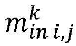
- the check-node to variable-node messages m out i , j k are computed from the variable-node to check-node messages m in i , j k .
- the belief propagation process is repeated iteratively until for instance a valid codeword is obtained, or a fixed number of iterations is reached.
- the check-node to variable-node messages can be updated in different sequences. Two sequences are: layered scheduling in which the check-node to variable-node messages are updated sequentially (i.e., one check node at a time), and flooded scheduling in which the check-node to variable-node messages of all check nodes are updated in parallel.
- a magnitude of the check-node to variable-node message m out i , j k that is sent to a specific variable node is approximated by the, in absolute value, smallest magnitude of the received variable-node to check-node messages m in i , j k excluding the message received from the variable node v i that the check-node to variable-node message m out i , j k will be sent to.
- the sign of the check-node to variable-node m out i , j k can be calculated as the product of the signs of the relevant variable-node to check-node messages.
- a correction may be applied to compensate for this effect.
- An exemplary correction is an attenuated min-sum decoder, where the check-node to variable-node messages are scaled with a factor ⁇ ⁇ 1.
- Another exemplary correction is an offset min-sum decoder, where an offset c offset > 0 is subtracted from the check node to variable node messages.
- Corrected min-sum decoders such as the attenuated min-sum decoders and offset min-sum decoders, provide a good compromise between decoding complexity and decoding performance.
- the correction which may be for example an attenuation or an offset, is conventionally applied after the min-operation.
- the check-node to variable-node messages m out i , j k do not use the full range of values that are available due to the bit-representation of these messages in hardware implementations.
- variable-node to check-node message m in i , j k is sent from a variable node v i to a check nodes c j and/or a check-node to variable-node message m out i , j k is sent from a check nodes c j to a variable node v i depends on the structure of the LDPC code.
- a nonzero entry in the N-K rows of the parity-check matrix H that comprise the check constraint defines that a variable-node to check-node message m in i , j k is sent from a variable node v i to a check node c j and that a check-node to variable-node message m out i , j k is sent from the check nodes c j to the variable node v i .
- the variable nodes v i are represented by the columns of the matrix H.
- the check nodes c j are represented by the rows of the matrix H.
- variable-node to check-node message m in i , j k is sent from the variable node v i to the check nodes c j and the check-node to variable-node message m out i , j k is sent from the check node c j to the variable node v i if the matrix element of the matrix H in the corresponding row and column is nonzero. Otherwise, no message is exchanged between these nodes.
- Figure 1 depicts schematically a first embodiment of an apparatus 102 for LDPC code decoding.
- the apparatus according to the first embodiment 102 is configured for receiving a first bit-word 104 of a first length, related to a log-likelihood ratio of a bit of a signal.
- the apparatus 102 is configured for mapping the first bit-word 104 in a first operation 106 to an intermediate bit-word 108 of the first length.
- the first operation 106 comprises determining the intermediate bit-word 108 as a fraction of the first bit-word 104.
- the fraction refers to a fraction of the value represented by the bit-word and is smaller than 1.
- the fraction may be determined by a binary shift operation or by a sum of several binary shift operations that are performed on the part of the first bit-word 104 that represents the magnitude.
- the fraction may be determined by mapping the first bit-word 104 to the intermediate bit-word 108 with a predetermined map.
- the map preferably defines a one-to-one mapping of any possible first bit-word to one intermediate bit-word. Several first bit-words may be mapped to the same intermediate bit-word.
- the mapping of the first bit-word 104 to the intermediate bit-word 108 may comprise looking up the intermediate bit-word 108 in a first table that includes a mapping of the first bit-word 104 to the intermediate bit-word 108.
- the apparatus according to the first embodiment 102 is configured for mapping the intermediate bit-word 108 in a second operation 110 to a second bit-word 112.
- the second operation 110 comprises determining the second bit-word 112 to have less bits than the intermediate bit-word 108.
- the second operation 110 may comprise mapping the intermediate bit-word 108 to the second bit-word 112 according to a predetermined map.
- the map preferably defines a one-to-one mapping of any possible intermediate bit-word to one second bit-word. Several intermediate bit-words may be mapped to the same second bit-word.
- the mapping of the intermediate bit-word 108 to the second bit-word 112 may comprise looking up the second bit-word 112 in a second table that includes a mapping of the intermediate bit-word 108 to the second bit-word 112.
- the apparatus according to the first embodiment 102 is configured for mapping the first bit-word 104 to the second bit-word 112.
- the second bit-word 112 is of a second length that is shorter than the first length.
- the apparatus according to the first embodiment 102 is configured for storing the second bit-word 112 to a memory. Aspects of processing of the second bit-word 112 are described below.
- the apparatus according to the first embodiment 102 may comprise a non-transitory computer readable medium comprising program instructions for causing the first apparatus to perform steps in a first method for low density parity check code decoding.
- the first method is described below with reference to figure 2 .
- the first method comprises a step 202.
- step 202 the first bit-word 104 of the first length is received.
- a step 204 is executed.
- the first bit-word 104 is mapped with the first operation 106 to the intermediate bit-word 108 of the first length.
- the intermediate bit-word 108 may be a fraction or an, in magnitude, offset value of the first bit-word 104.
- a step 206 is executed.
- step 206 the intermediate bit-word 108 is mapped with the second operation 110 to the second bit-word 112.
- a step 208 is executed.
- the second bit-word 112 is stored.
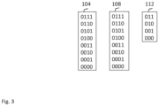
- Figure 3 depicts first exemplary bit-words, wherein the first bit-word 104 and the intermediate bit-word 108 have 4 bits and the second bit-word 112 has three bits.
- Figure 3 only the positive values are depicted. Only bit-words in which the first bit, or sign bit, is a 0, and which thus represent positive messages are shown. The first bit in the bit-word is the sign bit, and if it is one then the value is negative. There also exists bit words for negative values. These bit-words represent messages between the variable nodes v i and the check nodes c j . The length of the bit-words between the respective nodes, are of less length than the bit-words that are processed in the variable nodes. This reduces the resources that are required for communication significantly.
- Figure 4 depicts schematically a second embodiment 402 of the apparatus for LDPC code decoding.
- the apparatus according to the second embodiment 402 is configured for receiving a first bit-word 404 of a first length.
- the apparatus according to the second embodiment 402 is configured for mapping the first bit-word 404 in a first operation 406 to a second bit-word 408 while applying a correction.
- the first operation 406 comprises determining the second bit-word 408 to have less bits than the first bit-word 404.
- the first operation 406 may comprise mapping the first bit-word 404 to the second bit-word 408 according to a predetermined map comprising a correction.
- the map preferably defines a one-to-one mapping of any possible first bit-word to one second bit-word. Several first bit-words may be mapped to the same second bit-word.
- the mapping of the first bit-word 404 to the second bit-word 408 may comprise looking up the second bit-word 408 in a table that includes a mapping of the first bit-word 404 to the second bit-word 408 while applying a correction.
- the apparatus according to the second embodiment 402 is configured for mapping the first bit-word 404 to the second bit-word 408.
- the second bit-word 408 is of a second length that is shorter than the first length.
- the apparatus according to the second embodiment 402 is configured for storing the second bit-word 408 in a memory.
- the apparatus according to the second embodiment 402 may comprise a non-transitory computer readable medium comprising program instructions for causing the second apparatus to perform steps in a second method for low density parity check code decoding.
- the second method is described below with reference to figure 5 .
- the second method comprises a step 502.
- step 502 the first bit-word 404 of the first length is received.
- a step 504 is executed.
- the first bit-word 404 is mapped with the first operation 406 to the second bit-word 408 of the second length.
- the mapping comprises the correction.
- a step 506 is executed.
- the second bit-word 408 is stored.
- Figure 6 depicts first exemplary bit-words, wherein the first bit-word 404 has 4 bits and the second bit-word 408 has three bits.
- first bit-word 404 has 4 bits
- second bit-word 408 has three bits.
- Figure 6 only the positive values are depicted. Only bit-words in which the first bit, or sign bit, is a 0, and which thus represent positive messages are shown.
- the first bit in the bit-word is the sign bit, and if it is one then the value is negative. There also exists bit words for negative values.
- These bit-words represent messages between the variable nodes v i and the check nodes c j .
- the lenght of the bit-words that are exchanged between the respective nodes are of less length than the bit-words representing for instance total llrs that are processed in the variable nodes. This reduces the resources that are required for communication significantly.
- bit-words may represent signed values in various representation formats, like e.g., sign-magnitude representation or two 's-complement representation.
- 404 only represents the positive values of the mentioned representation formats.
- mapping For mapping, a linear mapping may be used, for example 0000 corresponds to 0, 0001 to 1, 0010 to 2, 0011 to 3, 0100 to 4, 0101 to 5, 0110 to 6, 0111 to 7.
- mapping For mapping, a nonlinear mapping may be used, for example, 000 corresponds to 0, 001 to 1, 010 to 3, and 011 to 5.
- Figure 7 depicts a first processing to calculate a check-node to variable-node message 700 corresponding to one variable node and one check node.
- the first processing relates to one iteration or update of an LDPC decoder for determining decoded bit values 702 depending on input log likelihood ratios 704.
- the decoded bits 702 are the signs of a total log likelihood ratio 706.
- the total log likelihood ratio 706 is determined depending on an addition 708 of the check-node to variable-node message 700 with a value 710 , that is determined depending on a difference 711 between a previously determined total log likelihood ratio that is sampled from a memory 712 of previously determined total log likelihood ratios and a previously determined check-node to variable-node message that is sampled from a memory 714 of previously determined check-node to variable-node messages.
- the value 710 and the check-node to variable-node message 700 in the example are values related to the same variable node v i and the same check node c j , and then their sum 708 is the total log likelihood ratio 706 of this variable node v i .
- the check-node to variable-node message 700 is determined depending on a set of first bit-words 716-1, ..., 716-h.
- the set of first bit-words 716-1, ..., 716-h is determined depending on a respective difference 718-1, ..., 718-h between a respective previously determined total log likelihood ratio that is sampled from the memory 712 of previously determined total log likelihood ratios and a respective previously determined check-node to variable-node message that is sampled from the memory 714 of previously determined check-node to variable-node messages.
- the check-node to variable-node message 700 is determined by processing 720 a set of second bit-words 722-1, ..., 722-h according to the configuration provided by the matrix H.
- the set of second bit-words 722-1, ..., 722-h is determined by applying a respective correction 724-1, ..., 724-h to the respective first bit-words 716-1, ..., 716-h.
- the first bit-words 716-1, ..., 716-h are bit-words of a first length, and the second bit-words 722-1, ..., 722-h bit-word of a second length.
- the second bit-words 722-1, ..., 722-h may be determined as described above with reference to figure 1 or 4 .
- the set of second bit-words 722-1, ..., 722-h may be provided to processing 720 in respective intermediate messages.
- the processing 720 may be configured to select as the magnitude of the check-node to variable-node message 700 the magnitude of the, in absolute value smallest bit-word of the set of second bit-words 722-1, ..., 722-h, and to calculate the sign of its check-node to variable-node message 700 as the product of the signs of the set of second bit-words 722-1, ..., 722-h.
- the first processing can be done in parallel or sequential, e.g. by the same processing unit.
- Processing can be shared across different variable nodes or check nodes. For example the same first bit-words can be re-used to calculate the check-node to variable-node message for the same check node but for different variable nodes.
- Figure 8 depicts a second processing to calculate a check-node to variable-node message 802 corresponding to one variable node and one check node.
- the second processing relates to one iteration or update of a LDPC decoder for determining decoded bit values 804 depending on an input log likelihood ratio 806.
- the decoded bits 804 are the signs of a total log likelihood ratio.
- the total log likelihood ratio is determined depending on a sum 808 of a set of check-node to variable-node messages that are sampled from a memory 810 that includes previously determined check-node to variable-node messages and an input log likelihood ratio that is samples from a memory 820 comprising a set of input log likelihood ratios.
- the check-node to variable-node message 802 is determined depending on a set of first bit-words 816-1, ..., 816-h.
- the set of first bit-words 816-1, ..., 816-h is determined depending on a respective sum 818-1, ..., 818-h of a respective input log likelihood ratio that is sampled from a memory 820 comprising a set of input log likelihood ratios and a set of previously determined check-node to variable-node messages that is sampled from the memory 810 of previously determined check-node to variable-node messages.
- the check-node to variable-node message 802 is determined by processing 820 a set of second bit-words 822-1, ..., 822-h according to the configuration provided by the matrix H.
- the set of second bit-words 822-1, ..., 822-h is determined by applying a respective correction 824-1, ..., 824-h to the respective first bit-words 816-1, ..., 816-h.
- the first bit-words 816-1, ..., 816-h are bit-words of a first length
- the second bit-words 822-1, ..., 822-h are bit-word of a second length.
- the second bit-words 822-1, ..., 822-h may be determined as described above with reference to figure 1 or 4 .
- the set of second bit-words 822-1, ..., 822-h may be provided to processing 820 in respective messages.
- the processing 820 may be configured to select as the magnitude of the check-node to variable-node message 800 the magnitude of the, in absolute value smallest bit-word of the set of second bit-words 822-1, ..., 822-h, and to calculate the sign of its check-node to variable-node message 800 as the product of the signs of the set of second bit-words 822-1, ..., 822-h.
- the processing can be done in parallel or sequential, e.g. by the same processing unit.
- Processing can be shared across different variable nodes or check nodes. For example the same first bit-words can be re-used to calculate the check-node to variable-node message for the same check node and different variable nodes.
- the sum 808 may be determined with a separate block or using one of the sum blocks that are used for determining the first bit-words.
Landscapes
- Engineering & Computer Science (AREA)
- Physics & Mathematics (AREA)
- Probability & Statistics with Applications (AREA)
- Theoretical Computer Science (AREA)
- Computer Networks & Wireless Communication (AREA)
- Signal Processing (AREA)
- Nonlinear Science (AREA)
- Error Detection And Correction (AREA)
Abstract
- receiving a first bit-word of a first length related to a log-likelihood ratio of a bit of a signal;
- obtaining a second bit-word of a second length that is shorter than the first length, wherein obtaining the second bit-word comprises applying a correction to the first bit-word;
- determining a message (700) depending on a set of second bit-words (722-1, ..., 722-h), wherein the set of second bit-words (722-1, ..., 722-h) includes the second bit-word.
Description
- Various example embodiments relate to an apparatus and a method for low density parity check code decoding.
- Low density parity check (LDPC) codes are forward error correction codes that are used to correct bit errors that occur during a transmission of data over a physical medium.
- Various embodiments of the disclosure are set out by the independent claims. The method and apparatus according to the independent claims are already incorporating a correction in variable-node to check node-messages. Because practical implementations of LDPC decoders represent values with limited size bit-words and because messages are represented by shorter bit-words compared to total log likelihood ratio values, the method and apparatus according to the independent claims make better use of available levels of bit-words in a LDPC code decoding process and therefor improve the performance of the LDPC decoding process.
- A method for low density parity check code decoding in a first processing device, disclosed herein, comprises receiving a first bit-word of a first length related to a log-likelihood ratio of a bit of a signal; obtaining a second bit-word of a second length that is shorter than the first length, wherein obtaining the second bit-word comprises applying a correction to the first bit-word; determining a message depending on a set of second bit-words, wherein the set of second bit-words includes the second bit-word.
- In one aspect of the disclosure, applying the correction comprises mapping the first bit-word to an intermediate bit-word of the first length, wherein a value represented by the intermediate bit-word is a fraction of a value represented by the first bit-word.
- In one aspect of the disclosure, applying the correction comprises mapping the first bit-word to an intermediate bit-word of the first length, wherein a magnitude of a value represented by the intermediate bit-word is a magnitude of a value represented by the first bit-word subtracted by an offset.
- In one aspect of the disclosure, applying the correction comprises looking up the second bit-word in a table that includes a mapping of the first bit-word to the second bit-word, wherein the mapping comprises the correction.
- The method may comprise determining a sign of the message depending on a product of signs of second bit-words in the set of second bit-words, and determining a magnitude of the message depending on a smallest magnitude of the second bit-words in the set of second bit-words.
- The method may comprise determining the first bit-word depending on a difference between a total log-likelihood ratio and a previously calculated message.
- An apparatus for low density parity check code decoding, comprises means for: receiving a first bit-word of a first length related to a log-likelihood ratio of a bit of a signal; obtaining a second bit-word of a second length that is shorter than the first length, wherein obtaining the second bit-word comprises applying a correction to the first bit-word; determining a message depending on a set of second bit-words, wherein the set of second bit-words includes the second bit-word.
- In one aspect of the disclosure, the apparatus comprises means that, to apply the correction, are configured for mapping the first bit-word to an intermediate bit-word of the first length, wherein a value represented by the intermediate bit-word is a fraction of a value represented by the first bit-word.
- In one aspect of the disclosure, the apparatus comprises means that, to apply the correction, are configured for mapping the first bit-word to an intermediate bit-word of the first length, wherein a magnitude of a value represented by the intermediate bit-word is a magnitude of a value represented by the first bit-word subtracted by an offset.
- In one aspect of the disclosure, the apparatus comprises means that, to apply the correction, are configured for looking up the second bit-word in a table that includes a mapping of the first bit-word to the second bit-word, wherein the mapping comprises the correction.
- In one aspect of the disclosure, the apparatus comprises means that are configured for determining a sign of the message depending on a product of signs of second bit-words in the set of second bit-words, and determining a magnitude of the message depending on a smallest magnitude of the second bit-words in the set of second bit-words.
- In one aspect of the disclosure, the apparatus comprises means that are configured for determining the first bit-word depending on a difference between a total log-likelihood ratio and a previously calculated message
- A non-transitory computer readable medium, disclosed herein, comprises program instructions for causing an apparatus to perform at least the method.
-
- Fig. 1
- schematically depicts parts of a first embodiment of an apparatus for low density parity check code decoding,
- Fig. 2
- depicts a sequence diagram comprising steps in a first embodiment of a method for use in low density parity check code decoding,
- Fig. 3
- depicts first exemplary bit-words,
- Fig. 4
- schematically depicts parts of a second embodiment of the apparatus for low density parity check code decoding,
- Fig. 5
- depicts a sequence diagram comprising steps in a second embodiment of the method for use in low density parity check code decoding,
- Fig. 6
- depicts second exemplary bit-words,
- Fig. 7
- depicts a first processing to calculate a message corresponding to a variable node and a check node,
- Fig. 8
- depicts a second processing to calculate a message corresponding to a variable node and a check node.
- An LDPC code is a block code that takes K information bits and encodes them into a codeword of N bits, which in an example disclosed herein, includes the K information bits in addition to N-K parity bits. A code rate R of the LDPC code is R=K/N.
- Examples of technologies that use LDPC code comprise wireless technologies, e.g. 5G, coaxial cable technologies, e.g. DOCSIS 3.1, Digital Subscriber Line technologies, e.g. MGfast, Passive Optical Network technologies, e.g. IEEE802.3ca and G.9804.2, power-line technologies, e.g. G.hn.
- An LDPC codeword comprises K information bits that correspond to information, e.g. data bits. The LDPC codeword comprises N-K bits that correspond to the N-K redundant parity bits. In the example, the first K bits in an order of the N bits of the LDPC codeword correspond to the K information bits and the last N-K bits in the order correspond to the parity bits.
- The characteristics of the LDPC are described by a binary (N-K) ×N parity check matrix H. The matrix H comprises N columns that correspond to the N bits of the LDPC codeword. The matrix H comprises N-K rows that correspond to check constraints that any valid codeword of the LDPC code should satisfy. In some embodiments, the LDPC code may be shortened by setting some information bits to a fixed value of for instance 0, and not transmitting these bits. Similarly, in some embodiments, the LDPC code may be punctured by not transmitting some of the encoded bits. With puncturing and shortening a (N-K) ×N parity check matrix H may be used to encode K' ≤K bits into a codeword of N' ≤N bits long, which may be non-systematic.
- The check constraints in the example are that an XOR-sum of the bits of the LDPC codeword indicated in the row of the parity check matrix has to be 0. Indicated in this context means that the matrix element is 1. This can be formally expressed as a matrix multiplication followed by a modulo-2 operation, e.g.:

- The LDPC code may be decoded using iterative belief propagation. Iterative belief propagation takes as input an initial log-likelihood ratios llrin,i of received bits vi that are calculated based on a received signal. The initial log-likelihood ratio llrin,i is the logarithm of the ratio of a probability P that the bit vi is a 0 given a received sample yi to a probability that the bit vi is a 1 given the received sample yi :

- The log-likelihood ratio llrin,i may also be calculated based on a set of received samples, for instance in case of digital equalization. For punctured bits, the initial log-likelihood ratio llrin,i can be set to 0, for shortened bits to a high positive value. A LDPC code decoding process that is based on belief propagation is an iterative process where messages are send from variable nodes vi to check nodes cj and vice versa. The N codeword bits are mapped in the LDPC code decoding process one to one to the variable nodes vi . The check nodes cj correspond to the N-K check constraints. This means, N-K check nodes cj are used.
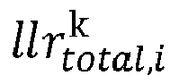
- In the example, the belief propagation process is a sum-product algorithm. In the belief propagation process initial log-likelihood ratios llrin,i are assigned to the total log-likelihood ratio


- Then, the iterative believe propagation process starts, wherein the variable-node to check-node message


- Next, the check-node to variable-node messages


- Then, the total log-likelihood ratio


- Here the sign of

- The belief propagation process is repeated iteratively until for instance a valid codeword is obtained, or a fixed number of iterations is reached. The check-node to variable-node messages can be updated in different sequences. Two sequences are: layered scheduling in which the check-node to variable-node messages are updated sequentially (i.e., one check node at a time), and flooded scheduling in which the check-node to variable-node messages of all check nodes are updated in parallel.
- In another example, a magnitude of the check-node to variable-node message


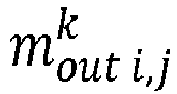
- This implementation is a min-sum decoder that is mathematically formulated as follows:

- These approximations overestimate the check-node to variable-node messages in case the magnitude of the smallest messages are similar.
- A correction may be applied to compensate for this effect.
- An exemplary correction is an attenuated min-sum decoder, where the check-node to variable-node messages are scaled with a factor ρ < 1. A corresponding attenuated min-sum algorithm is mathematically formulated as follows:

- Another exemplary correction is an offset min-sum decoder, where an offset coffset > 0 is subtracted from the check node to variable node messages. A corresponding offset min-sum algorithm is mathematically formulated as follows:

- Corrected min-sum decoders, such as the attenuated min-sum decoders and offset min-sum decoders, provide a good compromise between decoding complexity and decoding performance.
- When implementing the attenuated min-sum algorithm or the offset min-sum algorithm in tailored hardware implementations, minimizing a number of bits to represent the variable-node to check-node messages




- In corrected min-sum decoders, the correction, which may be for example an attenuation or an offset, is conventionally applied after the min-operation. As a consequence, the check-node to variable-node messages

- Applying the correction earlier in the processing, enables the check-node to variable-node messages to use the full range of values that are available.
- Whether a variable-node to check-node message




-
Figure 1 depicts schematically a first embodiment of anapparatus 102 for LDPC code decoding. - The apparatus according to the
first embodiment 102 is configured for receiving a first bit-word 104 of a first length, related to a log-likelihood ratio of a bit of a signal. - The
apparatus 102 according to the first embodiment is configured for mapping the first bit-word 104 in afirst operation 106 to an intermediate bit-word 108 of the first length. - In the example, the
first operation 106 comprises determining the intermediate bit-word 108 as a fraction of the first bit-word 104. In the context of this disclosure, the fraction refers to a fraction of the value represented by the bit-word and is smaller than 1. The fraction may be determined by a binary shift operation or by a sum of several binary shift operations that are performed on the part of the first bit-word 104 that represents the magnitude. - The fraction may be determined by mapping the first bit-
word 104 to the intermediate bit-word 108 with a predetermined map. The map preferably defines a one-to-one mapping of any possible first bit-word to one intermediate bit-word. Several first bit-words may be mapped to the same intermediate bit-word. - The mapping of the first bit-
word 104 to the intermediate bit-word 108 may comprise looking up the intermediate bit-word 108 in a first table that includes a mapping of the first bit-word 104 to the intermediate bit-word 108. - The apparatus according to the
first embodiment 102 is configured for mapping the intermediate bit-word 108 in asecond operation 110 to a second bit-word 112. In the example, thesecond operation 110 comprises determining the second bit-word 112 to have less bits than the intermediate bit-word 108. Thesecond operation 110 may comprise mapping the intermediate bit-word 108 to the second bit-word 112 according to a predetermined map. The map preferably defines a one-to-one mapping of any possible intermediate bit-word to one second bit-word. Several intermediate bit-words may be mapped to the same second bit-word. - The mapping of the intermediate bit-
word 108 to the second bit-word 112 may comprise looking up the second bit-word 112 in a second table that includes a mapping of the intermediate bit-word 108 to the second bit-word 112. - This means, the apparatus according to the
first embodiment 102 is configured for mapping the first bit-word 104 to the second bit-word 112. The second bit-word 112 is of a second length that is shorter than the first length. - The apparatus according to the
first embodiment 102 is configured for storing the second bit-word 112 to a memory. Aspects of processing of the second bit-word 112 are described below. - The apparatus according to the
first embodiment 102 may comprise a non-transitory computer readable medium comprising program instructions for causing the first apparatus to perform steps in a first method for low density parity check code decoding. - The first method is described below with reference to
figure 2 . - The first method comprises a
step 202. - In
step 202 the first bit-word 104 of the first length is received. - Afterwards, a
step 204 is executed. - In the
step 204, the first bit-word 104 is mapped with thefirst operation 106 to the intermediate bit-word 108 of the first length. - The intermediate bit-
word 108 may be a fraction or an, in magnitude, offset value of the first bit-word 104. - Afterwards, a
step 206 is executed. - In the
step 206 the intermediate bit-word 108 is mapped with thesecond operation 110 to the second bit-word 112. - Afterwards, a
step 208 is executed. - In the
step 208, the second bit-word 112 is stored. - Aspects of processing the second bit-
word 112 are described below. -
Figure 3 depicts first exemplary bit-words, wherein the first bit-word 104 and the intermediate bit-word 108 have 4 bits and the second bit-word 112 has three bits. InFigure 3 , only the positive values are depicted. Only bit-words in which the first bit, or sign bit, is a 0, and which thus represent positive messages are shown. The first bit in the bit-word is the sign bit, and if it is one then the value is negative. There also exists bit words for negative values. These bit-words represent messages between the variable nodes vi and the check nodes cj . The length of the bit-words between the respective nodes, are of less length than the bit-words that are processed in the variable nodes. This reduces the resources that are required for communication significantly. -
Figure 4 depicts schematically asecond embodiment 402 of the apparatus for LDPC code decoding. - The apparatus according to the
second embodiment 402 is configured for receiving a first bit-word 404 of a first length. - The apparatus according to the
second embodiment 402 is configured for mapping the first bit-word 404 in afirst operation 406 to a second bit-word 408 while applying a correction. In the example, thefirst operation 406 comprises determining the second bit-word 408 to have less bits than the first bit-word 404. Thefirst operation 406 may comprise mapping the first bit-word 404 to the second bit-word 408 according to a predetermined map comprising a correction. The map preferably defines a one-to-one mapping of any possible first bit-word to one second bit-word. Several first bit-words may be mapped to the same second bit-word. - The mapping of the first bit-
word 404 to the second bit-word 408 may comprise looking up the second bit-word 408 in a table that includes a mapping of the first bit-word 404 to the second bit-word 408 while applying a correction. - This means, the apparatus according to the
second embodiment 402 is configured for mapping the first bit-word 404 to the second bit-word 408. The second bit-word 408 is of a second length that is shorter than the first length. - The apparatus according to the
second embodiment 402 is configured for storing the second bit-word 408 in a memory. - The apparatus according to the
second embodiment 402 may comprise a non-transitory computer readable medium comprising program instructions for causing the second apparatus to perform steps in a second method for low density parity check code decoding. - The second method is described below with reference to
figure 5 . - The second method comprises a
step 502. - In
step 502 the first bit-word 404 of the first length is received. - Afterwards, a
step 504 is executed. - In the
step 504, the first bit-word 404 is mapped with thefirst operation 406 to the second bit-word 408 of the second length. The mapping comprises the correction. - Afterwards, a
step 506 is executed. - In the
step 506, the second bit-word 408 is stored. -
Figure 6 depicts first exemplary bit-words, wherein the first bit-word 404 has 4 bits and the second bit-word 408 has three bits. InFigure 6 , only the positive values are depicted. Only bit-words in which the first bit, or sign bit, is a 0, and which thus represent positive messages are shown. The first bit in the bit-word is the sign bit, and if it is one then the value is negative. There also exists bit words for negative values. These bit-words represent messages between the variable nodes vi and the check nodes cj . The lenght of the bit-words that are exchanged between the respective nodes, are of less length than the bit-words representing for instance total llrs that are processed in the variable nodes. This reduces the resources that are required for communication significantly. - Generally, the bit-words may represent signed values in various representation formats, like e.g., sign-magnitude representation or two 's-complement representation. 404 only represents the positive values of the mentioned representation formats.
- For mapping, a linear mapping may be used, for example 0000 corresponds to 0, 0001 to 1, 0010 to 2, 0011 to 3, 0100 to 4, 0101 to 5, 0110 to 6, 0111 to 7.
- For mapping, a nonlinear mapping may be used, for example, 000 corresponds to 0, 001 to 1, 010 to 3, and 011 to 5.
- With this approach the range of the messages can be further increased considerably. This is implemented by for instance implementing a block for performing the second operation based on a look up table that yields a correct magnitude of the output message levels based on the magnitude of the input messages.
-
Figure 7 depicts a first processing to calculate a check-node to variable-node message 700 corresponding to one variable node and one check node. The first processing relates to one iteration or update of an LDPC decoder for determining decodedbit values 702 depending on inputlog likelihood ratios 704. - The decoded
bits 702 are the signs of a totallog likelihood ratio 706. - The total
log likelihood ratio 706 is determined depending on anaddition 708 of the check-node to variable-node message 700 with avalue 710 , that is determined depending on adifference 711 between a previously determined total log likelihood ratio that is sampled from amemory 712 of previously determined total log likelihood ratios and a previously determined check-node to variable-node message that is sampled from amemory 714 of previously determined check-node to variable-node messages. Thevalue 710 and the check-node to variable-node message 700 in the example are values related to the same variable node vi and the same check node cj , and then theirsum 708 is the totallog likelihood ratio 706 of this variable node vi . - The check-node to variable-
node message 700 is determined depending on a set of first bit-words 716-1, ..., 716-h. The set of first bit-words 716-1, ..., 716-h is determined depending on a respective difference 718-1, ..., 718-h between a respective previously determined total log likelihood ratio that is sampled from thememory 712 of previously determined total log likelihood ratios and a respective previously determined check-node to variable-node message that is sampled from thememory 714 of previously determined check-node to variable-node messages. - The check-node to variable-
node message 700 is determined by processing 720 a set of second bit-words 722-1, ..., 722-h according to the configuration provided by the matrix H. The set of second bit-words 722-1, ..., 722-h is determined by applying a respective correction 724-1, ..., 724-h to the respective first bit-words 716-1, ..., 716-h. The first bit-words 716-1, ..., 716-h are bit-words of a first length, and the second bit-words 722-1, ..., 722-h bit-word of a second length. The second bit-words 722-1, ..., 722-h may be determined as described above with reference tofigure 1 or4 . The set of second bit-words 722-1, ..., 722-h may be provided toprocessing 720 in respective intermediate messages. In the example, theprocessing 720 may be configured to select as the magnitude of the check-node to variable-node message 700 the magnitude of the, in absolute value smallest bit-word of the set of second bit-words 722-1, ..., 722-h, and to calculate the sign of its check-node to variable-node message 700 as the product of the signs of the set of second bit-words 722-1, ..., 722-h. - The first processing can be done in parallel or sequential, e.g. by the same processing unit.
- Processing can be shared across different variable nodes or check nodes. For example the same first bit-words can be re-used to calculate the check-node to variable-node message for the same check node but for different variable nodes.
-
Figure 8 depicts a second processing to calculate a check-node to variable-node message 802 corresponding to one variable node and one check node. The second processing relates to one iteration or update of a LDPC decoder for determining decodedbit values 804 depending on an inputlog likelihood ratio 806. - The decoded
bits 804 are the signs of a total log likelihood ratio. The total log likelihood ratio is determined depending on asum 808 of a set of check-node to variable-node messages that are sampled from amemory 810 that includes previously determined check-node to variable-node messages and an input log likelihood ratio that is samples from amemory 820 comprising a set of input log likelihood ratios. - The check-node to variable-
node message 802 is determined depending on a set of first bit-words 816-1, ..., 816-h. The set of first bit-words 816-1, ..., 816-h is determined depending on a respective sum 818-1, ..., 818-h of a respective input log likelihood ratio that is sampled from amemory 820 comprising a set of input log likelihood ratios and a set of previously determined check-node to variable-node messages that is sampled from thememory 810 of previously determined check-node to variable-node messages. - The check-node to variable-
node message 802 is determined by processing 820 a set of second bit-words 822-1, ..., 822-h according to the configuration provided by the matrix H. The set of second bit-words 822-1, ..., 822-h is determined by applying a respective correction 824-1, ..., 824-h to the respective first bit-words 816-1, ..., 816-h. The first bit-words 816-1, ..., 816-h are bit-words of a first length, and the second bit-words 822-1, ..., 822-h are bit-word of a second length. The second bit-words 822-1, ..., 822-h may be determined as described above with reference tofigure 1 or4 . The set of second bit-words 822-1, ..., 822-h may be provided toprocessing 820 in respective messages. In the example, theprocessing 820 may be configured to select as the magnitude of the check-node to variable-node message 800 the magnitude of the, in absolute value smallest bit-word of the set of second bit-words 822-1, ..., 822-h, and to calculate the sign of its check-node to variable-node message 800 as the product of the signs of the set of second bit-words 822-1, ..., 822-h. - The processing can be done in parallel or sequential, e.g. by the same processing unit.
- Processing can be shared across different variable nodes or check nodes. For example the same first bit-words can be re-used to calculate the check-node to variable-node message for the same check node and different variable nodes.
- The
sum 808 may be determined with a separate block or using one of the sum blocks that are used for determining the first bit-words.
Claims (13)
- A method for use in low density parity check code decoding, wherein the method comprises:- receiving (202, 502) a first bit-word (104; 404; 716-1, ..., 716-h; 816-1, ..., 816-h) of a first length related to a log-likelihood ratio of a bit of a signal;- obtaining a second bit-word (112; 408; 722-1, ..., 722-h; 822-1, ..., 822-h) of a second length that is shorter than the first length, wherein obtaining the second bit-word (112; 408; 722-1, ..., 722-h; 822-1, ..., 822-h) comprises applying a correction to the first bit-word (104; 404; 716-1, ..., 716-h; 816-1, ..., 816-h);- determining a message (700, 802) depending on a set of second bit-words (722-1, ..., 722-h; 822-1, ..., 822-h), wherein the set of second bit-words (722-1, ..., 722-h; 822-1, ..., 822-h) includes the second bit-word (112; 408; 722-1, ..., 722-h; 822-1, ..., 822-h).
- The method of claim 1, wherein applying the correction comprises mapping (204) the first bit-word (104) to an intermediate bit-word (108) of the first length, wherein a value represented by the intermediate bit-word (108) is a fraction of a value represented by the first bit-word (104).
- The method of claim 1, wherein applying the correction comprises mapping (204) the first bit-word (104) to an intermediate bit-word (108) of the first length, wherein a magnitude of a value represented by the intermediate bit-word (108) is a magnitude of a value represented by the first bit-word (104) subtracted by an offset.
- The method of claim 1, wherein applying the correction (504) comprises looking up (504) the second bit-word (408) in a table that includes a mapping of the first bit-word (404) to the second bit-word (408), wherein the mapping comprises the correction.
- The method of one of the previous claims, comprising determining a sign of the message (700, 802) depending on a product of signs of second bit-words (112, 408) in the set of second bit-words (722-1, ..., 722-h; 822-1, ..., 822-h), and determining a magnitude of the message (700, 082) depending on a smallest magnitude of the second bit-words (112, 408) in the set of second bit-words (722-1, ..., 722-h; 822-1, ..., 822-h) .
- The method of one of the previous claims, comprising determining the first bit-word (716-1, ..., 716-h ; 816-1, ..., 816-h) depending on a difference between a total log-likelihood ratio and a previously calculated message (700, 802).
- An apparatus (102, 402) for low density parity check code decoding, wherein the apparatus (102, 402) comprises means for:- receiving (202, 502) a first bit-word (104; 404; 716-1, ..., 716-h ; 816-1, ..., 816-h) of a first length related to a log-likelihood ratio of a bit of a signal;- obtaining a second bit-word (112; 408; 722-1, ..., 722-h; 822-1, ..., 822-h) of a second length that is shorter than the first length, wherein obtaining the second bit-word (112; 408; 722-1, ..., 722-h; 822-1, ..., 822-h) comprises applying a correction to the first bit-word (104; 404; 716-1, ..., 716-h ; 816-1, ..., 816-h);- determining a message (700, 802) depending on a set of second bit-words (722-1, ..., 722-h; 822-1, ..., 822-h), wherein the set of second bit-words (722-1, ..., 722-h; 822-1, ..., 822-h) includes the second bit-word (112; 408; 722-1, ..., 722-h; 822-1, ..., 822-h).
- The apparatus (102) of claim 7, wherein the apparatus (102) comprises means that, to apply the correction, are configured for mapping (204) the first bit-word (104) to an intermediate bit-word (108) of the first length, wherein a value represented by the intermediate bit-word (108) is a fraction of a value represented by the first bit-word (104).
- The apparatus (102) of claim 7, wherein the apparatus (102) comprises means that, to apply the correction, are configured for mapping (204) the first bit-word (104) to an intermediate bit-word (108) of the first length, wherein a magnitude of a value represented by the intermediate bit-word (108) is a magnitude of a value represented by the first bit-word (104) subtracted by an offset.
- The apparatus (402) of claim 7, wherein the apparatus(402) comprises means that, to apply the correction, are configured for looking up (504) the second bit-word (408) in a table that includes a mapping of the first bit-word (404) to the second bit-word (408), wherein the mapping comprises the correction.
- The apparatus (102, 402) according to one of the claims 7 to 10, wherein the apparatus (102, 402) comprises means that are configured for determining a sign of the message (700, 802) depending on a product of signs of second bit-words (112, 408) in the set of second bit-words (722-1, ..., 722-h; 822-1, ..., 822-h), and determining a magnitude of the message (700, 802) depending on a smallest magnitude of the second bit-words (112, 408) in the set of second bit-words (722-1, ..., 722-h; 822-1, ..., 822-h).
- The apparatus (102, 402) according to one of the claim 7 to 11, wherein the apparatus (104, 404) comprises means that are configured for determining the first bit-word (716-1, ..., 716-h ; 816-1, ..., 816-h) depending on a difference between a total log-likelihood ratio and a previously calculated message (700, 802).
- A non-transitory computer readable medium comprising program instructions for causing an apparatus to perform at least the method of any of claims 1 to 6.
Priority Applications (3)
| Application Number | Priority Date | Filing Date | Title |
|---|---|---|---|
| EP21191119.3A EP4135205A1 (en) | 2021-08-12 | 2021-08-12 | Apparatus and method for low density parity check code decoding |
| CN202210955912.9A CN115706587A (en) | 2021-08-12 | 2022-08-10 | Apparatus and method for decoding low density parity check code |
| US17/885,896 US12531654B2 (en) | 2021-08-12 | 2022-08-11 | Apparatus and method for low density parity check code decoding |
Applications Claiming Priority (1)
| Application Number | Priority Date | Filing Date | Title |
|---|---|---|---|
| EP21191119.3A EP4135205A1 (en) | 2021-08-12 | 2021-08-12 | Apparatus and method for low density parity check code decoding |
Publications (1)
| Publication Number | Publication Date |
|---|---|
| EP4135205A1 true EP4135205A1 (en) | 2023-02-15 |
Family
ID=77316938
Family Applications (1)
| Application Number | Title | Priority Date | Filing Date |
|---|---|---|---|
| EP21191119.3A Pending EP4135205A1 (en) | 2021-08-12 | 2021-08-12 | Apparatus and method for low density parity check code decoding |
Country Status (3)
| Country | Link |
|---|---|
| US (1) | US12531654B2 (en) |
| EP (1) | EP4135205A1 (en) |
| CN (1) | CN115706587A (en) |
Citations (1)
| Publication number | Priority date | Publication date | Assignee | Title |
|---|---|---|---|---|
| US20160105199A1 (en) * | 2014-10-10 | 2016-04-14 | Tidal Systems, Inc. | Fast mapping method for layered min-sum decoding of ldpc codes, |
Family Cites Families (19)
| Publication number | Priority date | Publication date | Assignee | Title |
|---|---|---|---|---|
| US5596589A (en) * | 1993-10-29 | 1997-01-21 | Motorola, Inc. | Method and apparatus for encoding and decoding error correction codes in a radio communication system |
| US6393599B1 (en) * | 1999-07-06 | 2002-05-21 | Trw Inc. | Multi-chip data detector implementation for symmetric differential phase shift keying modulation formats |
| US6766490B1 (en) * | 2000-03-03 | 2004-07-20 | Palmone, Inc. | Reduced table size forward error correcting encoder |
| US6938196B2 (en) * | 2001-06-15 | 2005-08-30 | Flarion Technologies, Inc. | Node processors for use in parity check decoders |
| US6885711B2 (en) * | 2001-06-27 | 2005-04-26 | Qualcomm Inc | Turbo decoder with multiple scale selections |
| US7484158B2 (en) * | 2003-12-03 | 2009-01-27 | Infineon Technologies Ag | Method for decoding a low-density parity check (LDPC) codeword |
| CN101132252B (en) * | 2007-09-26 | 2011-05-25 | 东南大学 | A Quantized Min-Sum Decoding Method for Low Density Parity-Check Codes |
| WO2009043918A2 (en) * | 2007-10-02 | 2009-04-09 | Interuniversitair Microelectronica Centrum Vzw | An asip architecture for decoding at least two decoding methods |
| TWI469533B (en) * | 2008-11-07 | 2015-01-11 | Realtek Semiconductor Corp | Decoder for parity-check code and receiving system |
| JP4867980B2 (en) * | 2008-11-26 | 2012-02-01 | 住友電気工業株式会社 | Error correction decoding device |
| US8199034B2 (en) * | 2010-04-20 | 2012-06-12 | Qualcomm Incorporated | Method and apparatus for soft symbol determination |
| US8918694B2 (en) * | 2011-02-28 | 2014-12-23 | Clariphy Communications, Inc. | Non-concatenated FEC codes for ultra-high speed optical transport networks |
| US10230396B1 (en) * | 2013-03-05 | 2019-03-12 | Microsemi Solutions (Us), Inc. | Method and apparatus for layer-specific LDPC decoding |
| US8990661B1 (en) * | 2013-03-05 | 2015-03-24 | Pmc-Sierra Us, Inc. | Layer specific attenuation factor LDPC decoder |
| US9235467B2 (en) * | 2013-03-15 | 2016-01-12 | Pmc-Sierra Us, Inc. | System and method with reference voltage partitioning for low density parity check decoding |
| KR102241416B1 (en) * | 2013-09-16 | 2021-04-16 | 삼성전자주식회사 | Apparatus and method for decoding low density parity check(ldpc) codes in digital video broadcasting(dvb) system |
| US20170134048A1 (en) * | 2015-11-10 | 2017-05-11 | Samsung Electronics Co., Ltd. | Message-passing based decoding using syndrome information, and related methods |
| EP3264610A1 (en) * | 2016-06-27 | 2018-01-03 | Alcatel Lucent | Forward error correction with variable coding rate |
| US10691540B2 (en) * | 2017-11-21 | 2020-06-23 | SK Hynix Inc. | Soft chip-kill recovery for multiple wordlines failure |
-
2021
- 2021-08-12 EP EP21191119.3A patent/EP4135205A1/en active Pending
-
2022
- 2022-08-10 CN CN202210955912.9A patent/CN115706587A/en active Pending
- 2022-08-11 US US17/885,896 patent/US12531654B2/en active Active
Patent Citations (1)
| Publication number | Priority date | Publication date | Assignee | Title |
|---|---|---|---|---|
| US20160105199A1 (en) * | 2014-10-10 | 2016-04-14 | Tidal Systems, Inc. | Fast mapping method for layered min-sum decoding of ldpc codes, |
Non-Patent Citations (2)
| Title |
|---|
| ABU-SURRA SHADI ET AL: "Low-power dual quantization-domain decoding for LDPC codes", 8 December 2014 (2014-12-08) - 12 December 2014 (2014-12-12), pages 3151 - 3156, XP055876503, ISBN: 978-1-4799-3512-3, Retrieved from the Internet <URL:https://ieeexplore.ieee.org/stampPDF/getPDF.jsp?tp=&arnumber=7037290&ref=aHR0cHM6Ly9pZWVleHBsb3JlLmllZWUub3JnL2RvY3VtZW50LzcwMzcyOTA=> [retrieved on 20220105], DOI: 10.1109/GLOCOM.2014.7037290 * |
| LI MAO-RUEI ET AL: "A low-complexity LDPC decoder for NAND flash applications", PROC., IEEE INTERNATIONAL SYMPOSIUM ON CIRCUITS AND SYSTEMS (ISCAS), IEEE, 1 June 2014 (2014-06-01), pages 213 - 216, XP032624815, DOI: 10.1109/ISCAS.2014.6865103 * |
Also Published As
| Publication number | Publication date |
|---|---|
| US12531654B2 (en) | 2026-01-20 |
| US20230051030A1 (en) | 2023-02-16 |
| CN115706587A (en) | 2023-02-17 |
Similar Documents
| Publication | Publication Date | Title |
|---|---|---|
| KR20040101743A (en) | Apparatus and method for decoding of ldpc in a communication system | |
| US8601337B2 (en) | Decoding method and decoding device | |
| US20200044668A1 (en) | Method for ldpc decoding, ldpc decoder and storage device | |
| EP2169836A1 (en) | Low-density parity check convolution code (ldpc-cc) encoder and ldpc-cc decoder | |
| US11177834B2 (en) | Communication method and apparatus using polar codes | |
| KR20050100152A (en) | A decoding apparatus of low-density parity-check codes using sequential decoding, and a method thereof | |
| US8627153B2 (en) | Method and device for encoding symbols with a code of the parity check type and corresponding decoding method and device | |
| KR20090126829A (en) | Iterative decoding method and iterative decoding device | |
| CN107968657B (en) | Hybrid decoding method suitable for low-density parity check code | |
| US20160105199A1 (en) | Fast mapping method for layered min-sum decoding of ldpc codes, | |
| CN1953336B (en) | Method for updating check node in low density parity check decoder | |
| US8543889B2 (en) | Method of list decoding and relative decoder for LDPC codes | |
| CN104052499B (en) | Erasure correcting decoding method and system of LDPC code | |
| KR101657912B1 (en) | Method of Decoding Non-Binary Low Density Parity Check Codes | |
| CN113556135B (en) | Polar Code Belief Propagation Bit Flip Decoding Method Based on Frozen Flip List | |
| US8019020B1 (en) | Binary decoding for correlated input information | |
| US20020002695A1 (en) | Method and system for decoding | |
| US9026881B2 (en) | Soft input, soft output mappers and demappers for block codes | |
| CN119402017B (en) | A polar code soft-input soft-output decoding method, decoding device and communication equipment | |
| KR20090012189A (en) | Decoding Apparatus and Method Using Scaling-based Improved MINI-SMW Iterative Decoding Algorithm for Performance Improvement of LDPC Code | |
| US12531654B2 (en) | Apparatus and method for low density parity check code decoding | |
| KR101554488B1 (en) | Method and apparatus for decording of low density parity check code | |
| US10128981B1 (en) | Message-passing decoder with fast convergence and reduced storage | |
| KR101917829B1 (en) | Method and apparatus for deciding decoding order for shuffled decoding of ldpc codes | |
| Jia et al. | Design of improved error-rate sliding window decoder for SC-LDPC codes: reliable termination and channel value reuse |
Legal Events
| Date | Code | Title | Description |
|---|---|---|---|
| PUAI | Public reference made under article 153(3) epc to a published international application that has entered the european phase |
Free format text: ORIGINAL CODE: 0009012 |
|
| STAA | Information on the status of an ep patent application or granted ep patent |
Free format text: STATUS: THE APPLICATION HAS BEEN PUBLISHED |
|
| AK | Designated contracting states |
Kind code of ref document: A1 Designated state(s): AL AT BE BG CH CY CZ DE DK EE ES FI FR GB GR HR HU IE IS IT LI LT LU LV MC MK MT NL NO PL PT RO RS SE SI SK SM TR |
|
| STAA | Information on the status of an ep patent application or granted ep patent |
Free format text: STATUS: REQUEST FOR EXAMINATION WAS MADE |
|
| 17P | Request for examination filed |
Effective date: 20230406 |
|
| RBV | Designated contracting states (corrected) |
Designated state(s): AL AT BE BG CH CY CZ DE DK EE ES FI FR GB GR HR HU IE IS IT LI LT LU LV MC MK MT NL NO PL PT RO RS SE SI SK SM TR |
|
| STAA | Information on the status of an ep patent application or granted ep patent |
Free format text: STATUS: EXAMINATION IS IN PROGRESS |
|
| 17Q | First examination report despatched |
Effective date: 20240603 |