EP4135086A1 - Electrode packaging apparatus and method - Google Patents
Electrode packaging apparatus and method Download PDFInfo
- Publication number
- EP4135086A1 EP4135086A1 EP22771658.6A EP22771658A EP4135086A1 EP 4135086 A1 EP4135086 A1 EP 4135086A1 EP 22771658 A EP22771658 A EP 22771658A EP 4135086 A1 EP4135086 A1 EP 4135086A1
- Authority
- EP
- European Patent Office
- Prior art keywords
- electrode
- packaging bag
- packaging
- unit
- inlet
- Prior art date
- Legal status (The legal status is an assumption and is not a legal conclusion. Google has not performed a legal analysis and makes no representation as to the accuracy of the status listed.)
- Pending
Links
Images






Classifications
-
- B—PERFORMING OPERATIONS; TRANSPORTING
- B65—CONVEYING; PACKING; STORING; HANDLING THIN OR FILAMENTARY MATERIAL
- B65B—MACHINES, APPARATUS OR DEVICES FOR, OR METHODS OF, PACKAGING ARTICLES OR MATERIALS; UNPACKING
- B65B43/00—Forming, feeding, opening or setting-up containers or receptacles in association with packaging
- B65B43/42—Feeding or positioning bags, boxes, or cartons in the distended, opened, or set-up state; Feeding preformed rigid containers, e.g. tins, capsules, glass tubes, glasses, to the packaging position; Locating containers or receptacles at the filling position; Supporting containers or receptacles during the filling operation
- B65B43/54—Means for supporting containers or receptacles during the filling operation
-
- H—ELECTRICITY
- H01—ELECTRIC ELEMENTS
- H01M—PROCESSES OR MEANS, e.g. BATTERIES, FOR THE DIRECT CONVERSION OF CHEMICAL ENERGY INTO ELECTRICAL ENERGY
- H01M10/00—Secondary cells; Manufacture thereof
- H01M10/04—Construction or manufacture in general
- H01M10/0404—Machines for assembling batteries
- H01M10/0409—Machines for assembling batteries for cells with wound electrodes
-
- B—PERFORMING OPERATIONS; TRANSPORTING
- B65—CONVEYING; PACKING; STORING; HANDLING THIN OR FILAMENTARY MATERIAL
- B65B—MACHINES, APPARATUS OR DEVICES FOR, OR METHODS OF, PACKAGING ARTICLES OR MATERIALS; UNPACKING
- B65B23/00—Packaging fragile or shock-sensitive articles other than bottles; Unpacking eggs
-
- B—PERFORMING OPERATIONS; TRANSPORTING
- B65—CONVEYING; PACKING; STORING; HANDLING THIN OR FILAMENTARY MATERIAL
- B65B—MACHINES, APPARATUS OR DEVICES FOR, OR METHODS OF, PACKAGING ARTICLES OR MATERIALS; UNPACKING
- B65B43/00—Forming, feeding, opening or setting-up containers or receptacles in association with packaging
- B65B43/42—Feeding or positioning bags, boxes, or cartons in the distended, opened, or set-up state; Feeding preformed rigid containers, e.g. tins, capsules, glass tubes, glasses, to the packaging position; Locating containers or receptacles at the filling position; Supporting containers or receptacles during the filling operation
- B65B43/46—Feeding or positioning bags, boxes, or cartons in the distended, opened, or set-up state; Feeding preformed rigid containers, e.g. tins, capsules, glass tubes, glasses, to the packaging position; Locating containers or receptacles at the filling position; Supporting containers or receptacles during the filling operation using grippers
- B65B43/465—Feeding or positioning bags, boxes, or cartons in the distended, opened, or set-up state; Feeding preformed rigid containers, e.g. tins, capsules, glass tubes, glasses, to the packaging position; Locating containers or receptacles at the filling position; Supporting containers or receptacles during the filling operation using grippers for bags
-
- B—PERFORMING OPERATIONS; TRANSPORTING
- B65—CONVEYING; PACKING; STORING; HANDLING THIN OR FILAMENTARY MATERIAL
- B65B—MACHINES, APPARATUS OR DEVICES FOR, OR METHODS OF, PACKAGING ARTICLES OR MATERIALS; UNPACKING
- B65B5/00—Packaging individual articles in containers or receptacles, e.g. bags, sacks, boxes, cartons, cans, jars
- B65B5/04—Packaging single articles
- B65B5/045—Packaging single articles in bags
-
- B—PERFORMING OPERATIONS; TRANSPORTING
- B65—CONVEYING; PACKING; STORING; HANDLING THIN OR FILAMENTARY MATERIAL
- B65B—MACHINES, APPARATUS OR DEVICES FOR, OR METHODS OF, PACKAGING ARTICLES OR MATERIALS; UNPACKING
- B65B51/00—Devices for, or methods of, sealing or securing package folds or closures; Devices for gathering or twisting wrappers, or necks of bags
- B65B51/10—Applying or generating heat or pressure or combinations thereof
- B65B51/14—Applying or generating heat or pressure or combinations thereof by reciprocating or oscillating members
- B65B51/146—Closing bags
-
- B—PERFORMING OPERATIONS; TRANSPORTING
- B65—CONVEYING; PACKING; STORING; HANDLING THIN OR FILAMENTARY MATERIAL
- B65B—MACHINES, APPARATUS OR DEVICES FOR, OR METHODS OF, PACKAGING ARTICLES OR MATERIALS; UNPACKING
- B65B61/00—Auxiliary devices, not otherwise provided for, for operating on sheets, blanks, webs, binding material, containers or packages
- B65B61/20—Auxiliary devices, not otherwise provided for, for operating on sheets, blanks, webs, binding material, containers or packages for adding cards, coupons or other inserts to package contents
-
- H—ELECTRICITY
- H01—ELECTRIC ELEMENTS
- H01M—PROCESSES OR MEANS, e.g. BATTERIES, FOR THE DIRECT CONVERSION OF CHEMICAL ENERGY INTO ELECTRICAL ENERGY
- H01M10/00—Secondary cells; Manufacture thereof
- H01M10/04—Construction or manufacture in general
-
- H—ELECTRICITY
- H01—ELECTRIC ELEMENTS
- H01M—PROCESSES OR MEANS, e.g. BATTERIES, FOR THE DIRECT CONVERSION OF CHEMICAL ENERGY INTO ELECTRICAL ENERGY
- H01M10/00—Secondary cells; Manufacture thereof
- H01M10/04—Construction or manufacture in general
- H01M10/0431—Cells with wound or folded electrodes
-
- H—ELECTRICITY
- H01—ELECTRIC ELEMENTS
- H01M—PROCESSES OR MEANS, e.g. BATTERIES, FOR THE DIRECT CONVERSION OF CHEMICAL ENERGY INTO ELECTRICAL ENERGY
- H01M50/00—Constructional details or processes of manufacture of the non-active parts of electrochemical cells other than fuel cells, e.g. hybrid cells
- H01M50/10—Primary casings; Jackets or wrappings
- H01M50/102—Primary casings; Jackets or wrappings characterised by their shape or physical structure
- H01M50/105—Pouches or flexible bags
-
- H—ELECTRICITY
- H01—ELECTRIC ELEMENTS
- H01M—PROCESSES OR MEANS, e.g. BATTERIES, FOR THE DIRECT CONVERSION OF CHEMICAL ENERGY INTO ELECTRICAL ENERGY
- H01M50/00—Constructional details or processes of manufacture of the non-active parts of electrochemical cells other than fuel cells, e.g. hybrid cells
- H01M50/10—Primary casings; Jackets or wrappings
- H01M50/116—Primary casings; Jackets or wrappings characterised by the material
- H01M50/117—Inorganic material
- H01M50/119—Metals
-
- H—ELECTRICITY
- H01—ELECTRIC ELEMENTS
- H01M—PROCESSES OR MEANS, e.g. BATTERIES, FOR THE DIRECT CONVERSION OF CHEMICAL ENERGY INTO ELECTRICAL ENERGY
- H01M50/00—Constructional details or processes of manufacture of the non-active parts of electrochemical cells other than fuel cells, e.g. hybrid cells
- H01M50/10—Primary casings; Jackets or wrappings
- H01M50/116—Primary casings; Jackets or wrappings characterised by the material
- H01M50/121—Organic material
-
- H—ELECTRICITY
- H01—ELECTRIC ELEMENTS
- H01M—PROCESSES OR MEANS, e.g. BATTERIES, FOR THE DIRECT CONVERSION OF CHEMICAL ENERGY INTO ELECTRICAL ENERGY
- H01M50/00—Constructional details or processes of manufacture of the non-active parts of electrochemical cells other than fuel cells, e.g. hybrid cells
- H01M50/10—Primary casings; Jackets or wrappings
- H01M50/116—Primary casings; Jackets or wrappings characterised by the material
- H01M50/124—Primary casings; Jackets or wrappings characterised by the material having a layered structure
-
- H—ELECTRICITY
- H01—ELECTRIC ELEMENTS
- H01M—PROCESSES OR MEANS, e.g. BATTERIES, FOR THE DIRECT CONVERSION OF CHEMICAL ENERGY INTO ELECTRICAL ENERGY
- H01M50/00—Constructional details or processes of manufacture of the non-active parts of electrochemical cells other than fuel cells, e.g. hybrid cells
- H01M50/40—Separators; Membranes; Diaphragms; Spacing elements inside cells
- H01M50/471—Spacing elements inside cells other than separators, membranes or diaphragms; Manufacturing processes thereof
- H01M50/474—Spacing elements inside cells other than separators, membranes or diaphragms; Manufacturing processes thereof characterised by their position inside the cells
-
- H—ELECTRICITY
- H01—ELECTRIC ELEMENTS
- H01M—PROCESSES OR MEANS, e.g. BATTERIES, FOR THE DIRECT CONVERSION OF CHEMICAL ENERGY INTO ELECTRICAL ENERGY
- H01M50/00—Constructional details or processes of manufacture of the non-active parts of electrochemical cells other than fuel cells, e.g. hybrid cells
- H01M50/40—Separators; Membranes; Diaphragms; Spacing elements inside cells
- H01M50/471—Spacing elements inside cells other than separators, membranes or diaphragms; Manufacturing processes thereof
- H01M50/477—Spacing elements inside cells other than separators, membranes or diaphragms; Manufacturing processes thereof characterised by their shape
-
- H—ELECTRICITY
- H01—ELECTRIC ELEMENTS
- H01M—PROCESSES OR MEANS, e.g. BATTERIES, FOR THE DIRECT CONVERSION OF CHEMICAL ENERGY INTO ELECTRICAL ENERGY
- H01M10/00—Secondary cells; Manufacture thereof
- H01M10/05—Accumulators with non-aqueous electrolyte
- H01M10/058—Construction or manufacture
- H01M10/0587—Construction or manufacture of accumulators having only wound construction elements, i.e. wound positive electrodes, wound negative electrodes and wound separators
-
- Y—GENERAL TAGGING OF NEW TECHNOLOGICAL DEVELOPMENTS; GENERAL TAGGING OF CROSS-SECTIONAL TECHNOLOGIES SPANNING OVER SEVERAL SECTIONS OF THE IPC; TECHNICAL SUBJECTS COVERED BY FORMER USPC CROSS-REFERENCE ART COLLECTIONS [XRACs] AND DIGESTS
- Y02—TECHNOLOGIES OR APPLICATIONS FOR MITIGATION OR ADAPTATION AGAINST CLIMATE CHANGE
- Y02E—REDUCTION OF GREENHOUSE GAS [GHG] EMISSIONS, RELATED TO ENERGY GENERATION, TRANSMISSION OR DISTRIBUTION
- Y02E60/00—Enabling technologies; Technologies with a potential or indirect contribution to GHG emissions mitigation
- Y02E60/10—Energy storage using batteries
-
- Y—GENERAL TAGGING OF NEW TECHNOLOGICAL DEVELOPMENTS; GENERAL TAGGING OF CROSS-SECTIONAL TECHNOLOGIES SPANNING OVER SEVERAL SECTIONS OF THE IPC; TECHNICAL SUBJECTS COVERED BY FORMER USPC CROSS-REFERENCE ART COLLECTIONS [XRACs] AND DIGESTS
- Y02—TECHNOLOGIES OR APPLICATIONS FOR MITIGATION OR ADAPTATION AGAINST CLIMATE CHANGE
- Y02P—CLIMATE CHANGE MITIGATION TECHNOLOGIES IN THE PRODUCTION OR PROCESSING OF GOODS
- Y02P70/00—Climate change mitigation technologies in the production process for final industrial or consumer products
- Y02P70/50—Manufacturing or production processes characterised by the final manufactured product
Definitions
- the present invention relates to a device and a method for packing an electrode, more specifically, relates to a device and a method for packing an electrode for automatically packing electrodes.
- the rechargeable battery is attracting a lot of interest as an energy source for a power device such as an electric bicycle, an electric vehicle, and a hybrid electric vehicle as well as mobile devices such as mobile phones, digital cameras, notebook computers, and wearable devices.
- the rechargeable battery is classified into a cylindrical battery and a prismatic battery in which the electrode assembly is embedded in a cylindrical or prismatic metal can, and a pouch-type battery in which the electrode assembly is embedded in a pouch-type case of an aluminum laminate sheet.
- the rechargeable battery may be classified according to whether an electrode assembly of a structure in which a positive electrode, a negative electrode, and a separator interposed between the positive and negative electrodes are stacked is disposed.
- an electrode assembly of a structure in which a positive electrode, a negative electrode, and a separator interposed between the positive and negative electrodes are stacked is disposed.
- a jelly roll-type electrode assembly having a structure in which long sheet-shaped positive electrodes and negative electrodes are wound with a separator interposed therebetween, and a stack type electrode assembly in which a plurality of positive and negative electrodes cut by a unit of a predetermined size are sequentially stacked with a separator interposed therebetween may be mentioned.
- a stack/folding electrode assembly which is a mixture of the jelly roll type and stack type, has been developed.
- a method for manufacturing the electrode of the rechargeable battery As a method for manufacturing the electrode of the rechargeable battery, a method of dispersing an active material, a conductive material and/or a binder in a solvent to prepare a slurry and then applying the slurry directly to a current collector to form the electrode, or a method applying the slurry on an upper part of a separate support and then laminating a film to prevent it from being peeled off from the support on the current collector to form the electrode have been proposed.
- the sheet-shaped electrode (hereinafter referred to as an electrode sheet) formed by applying the slurry is mainly cut at regular intervals through a pressing, a slitting, or a drying process to produce unit electrodes such as positive or negative electrodes has been proposed.
- the electrode sheet may be moved or carried out in the wound state on a roll during or after the process described above, and may be packaged to minimize the influence of external air or moisture when moving or taking it out.
- the electrodes in the state before the assembly must be protected from the external environment, it is a fact that the electrode has been mainly packaged manually because there is no known electrode packaging device or known electrode packaging method in the prior art.
- the manual electrode packaging can not only damage the electrode, but also has several problems, such as increased labor costs due to use of additional personnel, and safety accidents caused by high-load electrodes.
- the task to be solved of the present invention is to provide an electrode packing device and a method therefor that may minimize damage to the electrode, reduce cost/time, and prevent safety accidents due to the electrode manufacturing.
- An electrode packing device includes: a transferring unit that transfers a wound electrode; and a packaging unit for packaging the electrode transferred by the transferring unit, wherein the packaging unit includes: a packaging bag supporting part for supporting the inlet of the packaging bag in an opened state; an electrode supporting part that supports the electrode from the outside the packaging bag, after the electrode is put into the packaging bag; and a sealing part that seals the inlet of the packaging bag, and the electrode supporting part includes a gripper that presses the core of the electrode and a side pad that presses the side of the electrode in a state in which the electrode is put in the packaging bag.
- the gripper may include two finger units, and the core of the electrode may be positioned between two finger units.
- the side pad may be plate-shaped, and a groove may be formed in the side pad to prevent interference with the gripper.
- the side pad may be semicircular in shape, and may be positioned below the gripper.
- the packaging bag supporting part may include at least one absorption unit, and the absorption unit may have an absorption surface that is vacuum-absorbed with one surface of the packaging bag.
- the sealing part may include a vacuum unit for removing air inside the packaging bag, and a heater unit for sealing the inlet of the packaging bag.
- the transferring unit may include a desiccant transferring unit for putting a desiccant into the packaging bag.
- the electrode packing device may further include a collecting unit in a form of a rack for placing the packaged electrode.
- An electrode packaging method includes: transferring a wound electrode to a packaging position by a transferring unit; inserting the electrode into the inlet of the packaging bag supported by the packaging bag supporting part; supporting the electrode from the outside the packaging bag by an electrode supporting part; and sealing the inlet of the packaging bag by a sealing part, wherein the supporting of the electrode includes pressing the core of the electrode through the gripper; and pressing the side of the electrode through the side pad.
- inserting the desiccant into the inlet of the packaging bag supported by the packaging bag supporting part may be further included.
- placing the packaged electrode to a collecting unit may be further included.
- the packaged electrode according to another embodiment of the present invention is packaged by the above-described electrode packing device.
- the packaged electrode may include an electrode wound with a rectangular electrode sheet and a packaging bag packaging the outer surface of the electrode, and the electrode and the packaging bag may be in close contact with each other.
- a desiccant provided inside the packaging bag may be further included.
- the packaging bag may include a first packaging bag and a second packaging bag, and the first packaging bag may be a polymer material, while the second packaging bag is a metal material.
- the present invention provides an automated electrode packing device and method, when the electrode is moved or taken out, damage to the electrode due to the external environment may be minimized, a labor cost for an electrode manufacturing may be reduced, and safety accidents caused by a high-load electrode may be prevented.
- the phrase “on a plane” means when an object portion is viewed from above, and the phrase “on a cross-section” means when a cross-section taken by vertically cutting an object portion is viewed from the side.
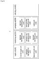
- FIG. 1 is a block diagram showing a configuration of an electrode packing device according to an embodiment of the present invention
- FIG. 2 is a block diagram showing a detailed configuration of an electrode packing device according to FIG. 1
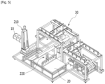
- FIG. 3 is a perspective view of an electrode packing device according to an embodiment of the present invention
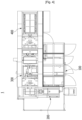
- FIG. 4 is a top plan view of an electrode packing device of FIG. 3 .
- an electrode packing device 1 may include a supply unit 100 for supplying an electrode 10, a packaging bag 20 or a desiccant 30, and the like, a transferring unit 200 for transferring the electrode 10, the packaging bag 20 or the desiccant 30, the like from the supply unit 100, a packaging unit 300 for packaging the electrode 10 by putting the electrode 10 into the packaging bag 20 and sealing the packaging bag 20 and/or a collecting unit 400 where the electrode 10 packaged by the packaging unit 300 stays before being taken out.
- the electrode 10 is a target of the electrode packing device 1, and may be a rectangular electrode sheet that is wound.
- the electrode sheet may be formed by coating the electrode slurry to the current collector, where the electrode slurry may typically include an electrode active material, a conductive material, a binder, and a solvent, but is not limited thereto.
- the current collector may be formed by using stainless steel, aluminum, copper, nickel, titanium, calcined carbon, etc,, and may be provided in various forms such as a film, a sheet, a foil, a net, a porous body, a foam, a non-woven fabric, etc..
- the packaging bag 20 may be for blocking the electrode 10 from the external environment by packaging the outer surface of the electrode 10.
- One side of the packaging bag 20 may be provided in an opened state so that the electrode 10 may be inserted.
- the other corners of the packaging bag 20 may be provided in a closed state to prevent the separation of the electrode 10.
- the packaging bag 20 may be in a completely closed state.
- the opened side of the packaging bag 20 is referred to as ' an inlet'.
- the packaging bag 20 may be manufactured of polyethylene (PE), high-density polyethylene (HDPE), low-density polyethylene (LDPE), polypropylene (PP), stretched polypropylene (OPP), polyethylene terephthalate) (PET), polyvinyl chloride (PVC), a deposited film (metalized film), or materials similar thereto.
- PE polyethylene
- HDPE high-density polyethylene
- LDPE low-density polyethylene
- PP polypropylene
- OPP stretched polypropylene
- PET polyethylene terephthalate
- PVC polyvinyl chloride
- metalized film metalized film
- the desiccant 30 may be for removing moisture remaining in the electrode 10 before being packaged in the packaging bag 20 or moisture that may be included in the packaging process.
- the desiccant 30 may be added before or after the electrode 10 is inserted, that is, before the packaging bag 20 is sealed.
- the desiccant 30 may be made of silica gel, but is not limited thereto.
- the supply unit 100 may refer to a space provided to store or stay the above-described electrode 10, packaging bag 20, or desiccant 30, or a configuration for this.
- the electrode 10, the packaging bag 20, or the desiccant 30 stored in the supply unit 100 may be moved to the packaging unit 300 by the transferring unit 200 and used in the packaging process.
- the supply unit 100 may include an electrode supply unit 110, a packaging bag supply unit 120, or a desiccant supply unit 130.
- the electrode 10 of the wound state may be sequentially supplied to the electrode supply unit 110.
- a plurality of packaging bags 20 may be stacked on the packaging bag supply unit 120.
- the packaging bag 20 may be stacked in the vertical direction so that one surface thereof faces an earth surface, but this is not necessarily the case, and may be differently disposed according to the intention of the designer.
- the desiccant 30 in a form of particles may be stored in the desiccant supply unit 130, or the desiccant 30 in a form of a pouch may be stacked and stored.
- the desiccant supply unit 130 may be disposed within a packaging position, where the 'the packaging position' may refer to a predetermined space provided for the inlet of the packaging bag 20 to be opened and the electrode 10 to be introduced through the inlet of the packaging bag 20.
- the transferring unit 200 may be for moving the electrode 10, the packaging bag 20, or the desiccant 30 stored/mounted in the supply unit 100 to the packaging position of the packaging unit 300.
- the transferring unit 200 may include an electrode transferring unit 210, a packaging bag transferring unit 220, or a desiccant transferring unit 230. Details of the transferring unit 200 are described later through drawings.
- the packaging unit 300 may be for sealing the electrode 10 transferred to the packaging position in the packaging bag 20.
- the packaging unit 300 may include an electrode supporting part 310 that trims the outer shape of the packaging bag 20 by supporting the electrode 10 from the outside the packaging bag 20, or a packaging bag supporting part 320 that opens the inlet of the packaging bag 20 and supports the opened inlet and/or a sealing part 330 for sealing the inlet after the electrode 10 is inserted. Further details of the packaging unit 300 are described later through drawings.
- the collecting unit 400 may refer to a space in which the packaged electrode 10 stays before being taken out or to a configuration therefor.
- the collecting unit 400 may include a rack on which the packaged electrode 10 may be mounted.
- the rack may include two bars spaced apart, and the core protruded to both ends on the width direction of the electrode 10 may be positioned on the two bars spaced apart.
- the core of the electrode 10 may be rolled on the bar, whereby the electrode 10 may be moved in the horizontal direction along the bar.
- the electrode 10 staying in the collecting unit 400 may be moved in a direction away from the packaging position along the bar by being pushed by the electrode 10 that is delivered later.
- a groove for limiting the range in which the electrode 10 moves may be provided in the bar.
- FIG. 5 is a view indicating a transferring unit of an electrode packing device according to an embodiment of the present invention
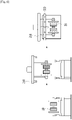
- FIG. 6 is a view showing an operation of an electrode transferring unit according to an embodiment of the present invention
- FIG. 7 is a view showing a packaging bag transferring unit according to an embodiment of the present invention
- FIG. 8 is a view showing a desiccant transferring unit according to an embodiment of the present invention.
- the electrode transferring unit 210 may move the electrode 10 supplied from the electrode supply unit 110 to the packaging position.
- the electrode transferring unit 210 may be designed so that it may be driven back and forth or left and right along the rail.
- the electrode transferring unit 210 may move the electrode 10 in the horizontal direction to correspond to the inlet of the packaging bag 20, and when the electrode 10 is positioned on the inlet of the packaging bag 20, the electrode 10 may be lowered to insert the electrode 10 into the packaging bag 20.
- the electrode transferring unit 210 of the present embodiment may include a lift or a hoist that can move the electrode 10 up and down.
- the above-described lift or hoist may include a hook 212 (referring to FIG. 9 ).
- the curved part of the hook may be designed to correspond to the core of the wound roll electrode 10.
- the electrode transferring unit 210 may be coupled to the core of the electrode 10 through a hook, and the electrode 10 may be suspended from the hook and lifted.
- the packaging bag transferring unit 220 may move the packaging bag 20 supplied from the packaging bag supply unit 120 to the packaging position.
- the packaging bag transferring unit 220 may be designed to be able to run forward or backward or left and right along the rail, which may be referred to as a body part (without reference numerals).
- the packaging bag transferring unit 220 may include an adsorption part 222 for lifting the packaging bag 20 and a tilting part 224 for tilting the adsorption part 222.
- the absorption part 222 of the packaging bag transferring unit 220 of the present embodiment may include a housing in which a hollow is formed and an adsorption unit temporarily attachable to an object by using a vacuum force formed by the hollow.
- the absorption unit is disposed on one surface of the housing, and if there are two or more absorption units, they may be disposed side by side along a straight line.
- Each absorption unit may have an absorption surface in contact with one surface of the packaging bag 20, and an absorption port communicating with the hollow of the housing may be positioned on the absorption surface.
- the absorption surface of the absorption unit can be moved to make an angle with or not to make an angle with a ground surface (a floor) by the tilting part 224 designed to be rotatable about the axis.
- the packaging bag 20 may be stacked so that one surface thereof is parallel to the ground surface, and the absorption unit of the packaging bag transferring unit 220 may be lowered so as to be close to one surface of the packaging bag 20 in a state where the absorption surface faces the ground surface.
- the absorption unit may be moved along the shown arrow by the tilting part 224, so that the absorption surface and one surface of the adsorbed packaging bag 20 absorbed with the absorption surface may be positioned to be vertical to the floor.
- the electrode 10 may be put into the packaging bag 20.
- the packaging bag transferring unit 220 may be designed to be movable up and down. This may be because the packaging bag supply unit 120 in which the packaging bag 20 is positioned has to be positioned close to the bottom surface, and the packaging bag transferring unit 220 has to be moved downward to obtain the packaging bag 20. In addition, this may be because the position of the packaging bag transferring unit 220 must be displaced to correspond to the position of the packaging bag supporting part 320 to be described later.
- the desiccant transferring unit 230 may be for putting the desiccant 30 into the packaging bag 20. As shown in FIG. 8 , the desiccant 30 may be put into the packaging bag 20 along the arrow direction by the desiccant transferring unit 230 of the present embodiment.
- the desiccant transferring unit 230 may be designed as a robot for putting the desiccant 30 stored in the desiccant supply unit 130 into the packaging bag 20.
- the desiccant transferring unit 230 may be positioned in a space in which the inlet of the packaging bag 20 is opened to facilitate the input of the desiccant 30, and specifically, the desiccant transferring unit 230 may be positioned above the opened inlet of the packaging bag 20 have.
- the packaging bag supporting part 320 if the packaging bag 20 moves to the packaging position by the above-described packaging bag transferring unit 220, by supporting one surface of the packaging bag 20, the inlet of the packaging bag 20 may be opened, and the opened inlet may be maintained.
- FIG. 9 is a view showing an operation of a packaging bag supporting part according to an embodiment of the present invention.
- the packaging bag supporting part 320 may include the absorption part 322 to support the packaging bag 20, and the absorption part 322 of the packaging bag supporting part 320 may be designed similar to the absorption part 222 of the above-described packaging bag transferring unit 220. Substantially, the absorption part 322 of the packaging bag supporting part 320 and the absorption part 222 of the packaging bag transferring unit 220 are substantially the same, but may be separated for convenience of explanation, and may be provided to be symmetrical to each other.
- the packaging bag supporting part 320 may open the inlet of the packaging bag 20.
- One surface of the packaging bag 20 is vacuum-adsorbed by the absorption part 222 of the packaging bag transferring unit 220 and moved to the packaging position, and the other surface of the moved packaging bag 20 may be supported by the vacuum adsorption by the absorption part 322 of the packaging bag supporting part 320.
- the packaging bag transferring unit 220 and the packaging bag supporting part 320 attached to two surfaces of the packaging bag 20 may move in opposite directions, whereby the inlet of the packaging bag 20 may be opened.
- the packaging bag supporting part 320 may be designed to be movable up and down. This may be because the packaging bag transferring unit 220 and the packaging bag supporting part 320 must be displaced to correspond to each other. Also, this may be in order to adjust the distance between the transferred electrode 10 and the inlet of the packaging bag 20. Specifically, when the high load electrode 10 falls into the packaging bag 20, there is a fear that the packaging bag 20 is damaged. Accordingly, it may be preferable to minimize the falling distance of the electrode 10 by moving the packaging bag transferring unit 220 and/or the packaging bag supporting part 320 supporting the packaging bag 20 upward.
- the operation of the sealing part 330 in the packaging process of the electrode 10 may be linked with the operation of the packaging bag transferring unit 220 and/or the packaging bag supporting part 320, and in this process, the packaging bag transferring unit 220 and/or packaging bag supporting part 320 may have to be moved up and down so that the sealing part 330 and the position thereof correspond as much as possible.
- the electrode 10 when the packaging of the electrode 10 is completed, the electrode 10 may be hung on the rack of the collecting unit 400 and stored until taken out. At this time, if the packaging bag 20 is not in close contact along the outer shape of the electrode 10, it may be difficult for the core of the electrode 10 to be seated on the rack, and the packaging bag 20 may be damaged due to a tension acting around the core of the electrode 10 caught in the rack. Therefore, before the packaging of the electrode 10 is completed, the electrode supporting part 310 for arranging the appearance of the packaging bag 20 may be required.
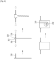
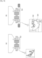
- FIG. 10 is a view showing an operation of an electrode supporting part according to an embodiment of the present invention.
- the electrode supporting part 310 may be for trimming the appearance of the packaging bag 20 after the electrode 10 is put into the packaging bag 20.
- the electrode supporting part 310 may include a gripper 312 for pressing the core of the electrode 10 and a side pad 314 for pressing the side of the electrode 10.
- Two gripper 312 and two side pad 314 may be provided, respectively, the gripper 312 may be disposed to pressurize the core protruded from both ends in the width direction of the electrode 10, and the side pad 314 may be disposed at both ends in the width direction of the electrode 10 to pressurize a radial cross-section (the side) of the wound electrode 10.
- the gripper 312 may include two finger units, and each finger unit may be provided in a round shape.
- the core of the electrode 10 is mainly positioned between two finger units, but even if it is initially disposed to a different position, it may be moved and disposed between two finger units due to its round shape.
- the finger unit may move independently, and both ends of the electrode 10 may be spread apart or come closer so that the core of the electrode 10 may be seated on the gripper 312.
- the gripper 312 may grip the core of the electrode 10.
- the side pad 314 may be provided in a circular or semicircular shape corresponding to the radial cross-section of the wound roll electrode 10.
- the side pad 314 may be provided in a plate shape, and since the gripper 312 is positioned around the core of the electrode 10, a groove may be formed in the side pad 314 to prevent an interference with the gripper 312.
- the electrode 10 is seated in the rack of the collecting unit 400, since the tension mainly acts between the core of electrode 10 and the bottom surface of electrode 10, it may be preferable that the side pad 314 mainly presses the lower part of the cross-section of the electrode 10. Therefore, in order to minimize the interference between the electrode 10 and the collecting unit 400, the side pad 314 may be provided in a semicircular plate shape to correspond to the lower portion of the cross-section of the electrode 10 under the gripper 312 as shown.
- the inlet of the packaging bag 20 may be sealed by the sealing part 330.
- FIG. 11 is a view showing a sealing part according to an embodiment of the present invention.
- the sealing part 330 may include a vacuum unit 332 for removing an air inside the packaging bag 20 and a heater unit 334 for sealing the inlet.
- the vacuum unit 332 may create a vacuum environment in the packaging bag 20.
- the vacuum unit 332 is disposed between the absorption part 222 of the packaging bag transferring unit 220 and the absorption part of the packaging bag supporting part 320, thereby it is possible to remove the air in the packaging bag 20.
- the vacuum unit 332 may allow the packaging bag 20 to be in close contact with the outer surface of the electrode 10 .
- the packaging bag transferring unit 220 and the packaging bag supporting part 320 may move toward each other so that the inlet of the packaging bag 20 corresponds to the vacuum unit 332 .
- the heater unit 334 moves toward the packaging bag 20, and a portion of the packaging bag 20 is heat-sealed by the heater unit 334, so that the inlet of the packaging bag 20 may be closed.
- a pair of heater units 334 may be provided, and a pair of heater units 334 may be respectively positioned on two surfaces of the packaging bag 20 to seal the inlet by pressing the packaging bag 20.
- the sealing part 330 may further include a clamp unit (not shown) for straightening the wrinkles of the packaging bag 20 before the operation of the vacuum unit 332 or the heater unit 334 described above.
- the clamp unit may be provided as a pair of finger units, but the shape of the finger unit may be different from that of the finger unit of the gripper 312 described above.
- the clamp unit may be for arranging the inlet of the packaging bag 20 positioned on the circumferential surface of the electrode 10 or on both radial cross-sections of the electrode 10.
- the clamp unit may be for forming at least a portion of the inlet of the packaging bag 20 deformed according to the shape of the electrode 10 in a straight shape.
- a plurality of clamp units may be provided along the axial direction of the electrode 10 or one surface of the packaging bag 20.
- the clamp unit is a configuration of the sealing part 330, but considering the function of the clamp unit supporting the packaging bag 20, the clamp unit may be provided as a configuration of the packaging bag supporting part 320. Accordingly, the packaging bag supporting part 320 may include an absorption part 322 including the above-described absorption unit and a clamp unit.
- each configuration of the electrode packing device described above may be provided in a form in which a part is omitted as necessary, or may be provided in a form further including an additional configuration, this have to be interpreted to be also included in the spirit of the present invention.
- the desiccant 30 may be optionally provided.
- a material having a component similar to that of desiccant 30 may be coated to the inner surface of the packaging bag 20, it may not be necessary to add an additional desiccant 30 to the packaging bag 20.
- the desiccant supply unit 130 and the desiccant transferring unit 230 included in the electrode packing device 1 of the present invention may be omitted, and it is self-evident that the electrode packing device 1 without such a configuration also belongs to the spirit of the present invention.
- the electrode packaging method according to an embodiment of the present invention may be performed by the above-described electrode packing device. But, it is not necessarily.
- FIG. 12 is a flowchart of an electrode packaging method according to an embodiment of the present invention.
- an electrode packaging method S100 may include transferring a wound electrode 10 (S110), transferring a packaging bag 20 (S120), inserting the electrode 10 into the packaging bag 20 (S130), inserting the desiccant 30 in the packaging bag 20 (S140), arranging the appearance of the packaging bag 20 (S150), sealing the inlet of the packaging bag 20 (S160), and/or mounting the packaged electrode 10 (S170).
- the procedure of the electrode packaging method S100 is not limited to the above, and the method may be performed in another order.
- transferring the wound electrode 10 (S110) and the transferring the packaging bag 20 (S120) may be simultaneously performed, and transferring the wound electrode 10 (S110) may be performed after transferring the packaging bag 20 (S120).
- inserting the desiccant 30 into the packaging bag 20 (S140) may be performed before inserting the electrode 10 into the packaging bag 20 (S130).
- the electrode packaging method S100 may exclude some of the above-described steps, or may further include an additional step. For example, inserting the desiccant 30 into the packaging bag 20 (S140) in the electrode packaging method S100 may be omitted.
- the electrode 10 positioned in the electrode supply unit 110 may be moved to the packaging position by the electrode transferring unit 210 (S110). This may be explained with reference to the above content, and more specifically, may be described with reference to the content of FIG. 5 and FIG. 6 .
- the packaging bag 20 positioned in the packaging bag supply unit 120 may be moved to the packaging position by the packaging bag transferring unit 220 S120. This may be explained with reference to the above content, and more specifically, may be described with reference to the content of FIG. 5 and FIG. 7 .
- the packaging bag 20 may be lifted by the absorption part 222 of the packaging bag transferring unit 220, and then moved to the packaging position through a body part to be drivable (no reference numeral).
- the absorption surface of the absorption part 222 is attached to one surface of packaging bag 20
- the tilting part 224 rotates about the axis
- the absorption surface of the absorption part 222 may be positioned vertically to the floor, and one surface of the packaging bag 20 may be moved to the packaging position in a state vertical to the floor.
- one surface of the packaging bag 20 may be positioned in a state vertical to the floor by the operation of the tilting part 224.
- the electrode 10 may be transferred into the inlet of the packaging bag 20 opened by the electrode transferring unit 210 (S130).
- the inlet of the packaging bag 20 may be opened and supported by the packaging bag supporting part 320.
- the inlet of the packaging bag 20 may be opened and supported by the packaging bag transferring unit 220 and the packaging bag supporting part 320.
- inserting the electrode 10 into the packaging bag 20 may include opening the inlet of the packaging bag 20 (S132) and inserting the electrode 10 into the inlet of the packaging bag 20 (S134). Opening the inlet of the packaging bag 20 (S132) may be described with reference to the content of FIG. 9 and inserting the electrode 10 into the inlet of the packaging bag 20 (S134) may be described with reference to the content of FIG. 6 .
- the desiccant 30 positioned in the desiccant supply unit 130 may be put into the inlet of the packaging bag 20 by the desiccant transferring unit 230 (S140). This may be explained with reference to the above content, and more specifically, it may be described with reference to the contents of FIG. 8 .
- the outer shape of the packaging bag 20 may be arranged by the electrode supporting part 310 S150. This may be explained with reference to the above content, and more specifically, it may be described with reference to the contents of FIG. 10 .
- the sealing part 330 may seal the inlet of the packaging bag 20 S160. This may be explained with reference to the above content, and more specifically, it may be described with reference to the contents of FIG. 11 .
- the shape of the inlet of the packaging bag 20 may be adjusted by the above-described finger unit. After the operation of the finger unit, the outer surface of the electrode 10 and the packaging bag 20 may be in close contact by the vacuum unit 332, and the inlet of the packaging bag 20 may be sealed by the heater unit 334.
- the packaged electrode 10 may be placed in the collecting unit 400 until it is taken out (S170). This may be described with reference to the content of the collecting unit 400, so a detailed description is omitted.
- the electrode 10 is packaged by one packaging bag 20, but the electrode 10 may be packaged by two or more packaging bags 20.
- the packaging bag 20 may include a first packaging bag and a second packaging bag.
- the first packaging bag may be made of a polymer material
- the second packaging bag may be made of a metal material.
- An example of a metal material for the second packaging bag is aluminum.
- the above-described packaging bag 20 such as PE and the packaging bag 20 of a metal material such as aluminum may be provided, specifically, after the electrode 10 is packaged with the packaging bag 20 of a polymer material, it may be re-packaged with the packaging bag 20 of the metal material.
- the above-described electrode packing device and method may be partially modified to perform a continuous process by two packaging bags 20.
- the packaging bag supply unit 120 of the electrode packing device 1 may include a first packaging bag supply unit and a second packaging bag supply unit for storing each packaging bag 20.
- the first packaging bag supply unit may supply the first packaging bag
- the second packaging bag supply unit may supply the second packaging bag.
- the electrode packaging method S100 before placing the packaged electrode 10 (S170), may again repeat transferring the packaging bag 20 (S120), inserting the electrode 10 in the packaging bag 20 (S130), inserting the desiccant 30 in the packaging bag 20 (S140), arranging the appearance of the packaging bag 20 (S150) or sealing the inlet of the packaging bag 20 (S160).
- the repeating of the steps (S120) to (S160) may be packaging the electrode packaged with the first packaging bag into the second packaging bag. Therefore, in the steps (S120) to (S160) before the repeating, the packaging bag 20 may be described as a first packaging bag, and in the repeating of the steps (S120) to (S160), the electrode 10 may be described as an electrode packaged with the first packaging bag, and the packaging bag 20 may be described as the second packaging.
- the electrode packaging method S100 may not repeat all of the steps (S120) to (S160), but only some of them may be repeated. For example, in the electrode packaging method S100, inserting the desiccant 30 into the packaging bag 20 (S140) may not be repeated again. At this time, the desiccant 30 may be provided only to the packaging bag 20 positioned inside. Alternatively, the electrode packaging method S100 may not repeat arranging the appearance of the packaging bag 20 (S150) again.
- the packaged electrode of the present embodiment is packaged by the above-described electrode packing device 1 and electrode packaging method 100S, and the contents overlapping with the above-described contents are omitted.
- the packaged electrode of the present embodiment may include the electrode 10 wound in a rectangular electrode sheet and the packaging bag 20 for packaging the outer surface of the electrode 10.
- the packaged electrode of the present embodiment may further include a desiccant 30 for removing moisture inside the packaging bag 20.
- the electrode 10 may be packaged in the packaging bag 20 by the electrode packing device 1 and the electrode packaging method 100S described above. In the packaged electrode, the electrode 10 and the packaging bag 20 may be in close contact. The electrode 10 and the packaging bag 20 may in contact with each other. This may be because, after the electrode 10 is put into the packaging bag 20, the inside of the packaging bag 20 is adjusted in a vacuum state by the vacuum unit 332, and then the inlet is sealed by the heater unit 334.
- the electrode 10 may be doubly packaged.
- the electrode 10 may be packaged in two or more packaging bags 20.
- the packaging bag 20 may include a first packaging bag and a second packaging bag. After being packaged in the first packaging bag, the electrode 10 may be packaged in the second packaging bag. In the packaged electrode, the first packaging bag may be positioned inside the second packaging bag, and the second packaging bag may be positioned outside the first packaging bag.
- the electrode 10 When the electrode 10 is double packaged, the electrode 10 may be put into the second packaging bag after being packaged with the first packaging bag by the above-described electrode packing device 1 and electrode packaging method 100S, and the inlet of the second packaging bag may be sealed, thereby the packaging of the electrode may be completed.
- the desiccant 30 may be provided inside the first packaging bag before the sealing of the first packaging bag. In addition, the desiccant 30 may be provided inside the second packaging bag before the sealing of the second packaging bag.
- the first packaging bag may be a polymer material
- the second packaging bag may be a metal material.
- moisture resistance of the packaged electrode may be improved.
- the second packaging bag blocks the first packaging bag from the external environment, the damage to the first packaging bag due to the storage or transport may be prevented, and a durability of the packaged electrode may be improved.
Landscapes
- Chemical & Material Sciences (AREA)
- Chemical Kinetics & Catalysis (AREA)
- Electrochemistry (AREA)
- General Chemical & Material Sciences (AREA)
- Engineering & Computer Science (AREA)
- Mechanical Engineering (AREA)
- Manufacturing & Machinery (AREA)
- Inorganic Chemistry (AREA)
- Packages (AREA)
Abstract
Description
- This application claims priority to and the benefit of
Korean Patent Application No. 10-2021-0034183 filed in the Korean Intellectual Property Office on March 16, 2021 Korean Patent Application No. 10-2022-0012249 filed in the Korean Intellectual Property Office on January 27, 2022 - The present invention relates to a device and a method for packing an electrode, more specifically, relates to a device and a method for packing an electrode for automatically packing electrodes.
- As development of technologies and demands for mobile devices are increased, there is a rapidly increasing demand for rechargeable batteries as energy sources. Particularly, the rechargeable battery is attracting a lot of interest as an energy source for a power device such as an electric bicycle, an electric vehicle, and a hybrid electric vehicle as well as mobile devices such as mobile phones, digital cameras, notebook computers, and wearable devices.
- According to a shape of a battery case, the rechargeable battery is classified into a cylindrical battery and a prismatic battery in which the electrode assembly is embedded in a cylindrical or prismatic metal can, and a pouch-type battery in which the electrode assembly is embedded in a pouch-type case of an aluminum laminate sheet.
- In addition, the rechargeable battery may be classified according to whether an electrode assembly of a structure in which a positive electrode, a negative electrode, and a separator interposed between the positive and negative electrodes are stacked is disposed. Typically, a jelly roll-type electrode assembly having a structure in which long sheet-shaped positive electrodes and negative electrodes are wound with a separator interposed therebetween, and a stack type electrode assembly in which a plurality of positive and negative electrodes cut by a unit of a predetermined size are sequentially stacked with a separator interposed therebetween may be mentioned. Recently, in order to solve the problem of the jelly roll electrode assembly and the stack electrode assembly, a stack/folding electrode assembly, which is a mixture of the jelly roll type and stack type, has been developed.
- As a method for manufacturing the electrode of the rechargeable battery, a method of dispersing an active material, a conductive material and/or a binder in a solvent to prepare a slurry and then applying the slurry directly to a current collector to form the electrode, or a method applying the slurry on an upper part of a separate support and then laminating a film to prevent it from being peeled off from the support on the current collector to form the electrode have been proposed. The sheet-shaped electrode (hereinafter referred to as an electrode sheet) formed by applying the slurry is mainly cut at regular intervals through a pressing, a slitting, or a drying process to produce unit electrodes such as positive or negative electrodes has been proposed.
- On the other hand, the electrode sheet may be moved or carried out in the wound state on a roll during or after the process described above, and may be packaged to minimize the influence of external air or moisture when moving or taking it out. In order to minimize a defect rate of a final product, although the electrodes in the state before the assembly must be protected from the external environment, it is a fact that the electrode has been mainly packaged manually because there is no known electrode packaging device or known electrode packaging method in the prior art. However, the manual electrode packaging can not only damage the electrode, but also has several problems, such as increased labor costs due to use of additional personnel, and safety accidents caused by high-load electrodes.
- In addition, for the safe packaging of the electrode, a method of wrapping the electrode by wrapping a wrapping paper around the wound electrode circumference has been devised, but it has not only been weak in protecting both sides of the electrode, but also had a problem in that vacuum packaging was impossible.
- Considering a recent surge in market demand for the rechargeable batteries, it is difficult to continue the manual electrode packaging like the present one, so a standardized packaging method or a device therefor for safely moving the electrode is needed.
- The task to be solved of the present invention is to provide an electrode packing device and a method therefor that may minimize damage to the electrode, reduce cost/time, and prevent safety accidents due to the electrode manufacturing.
- The problem to be solved by the present invention is not limited to the above-mentioned problems, and problems not mentioned will be clearly understood by those of ordinary skill in the art to which the present invention belongs from the present specification and the accompanying drawings.
- An electrode packing device according to an embodiment of the present invention includes: a transferring unit that transfers a wound electrode; and a packaging unit for packaging the electrode transferred by the transferring unit, wherein the packaging unit includes: a packaging bag supporting part for supporting the inlet of the packaging bag in an opened state; an electrode supporting part that supports the electrode from the outside the packaging bag, after the electrode is put into the packaging bag; and a sealing part that seals the inlet of the packaging bag, and the electrode supporting part includes a gripper that presses the core of the electrode and a side pad that presses the side of the electrode in a state in which the electrode is put in the packaging bag.
- The gripper may include two finger units, and the core of the electrode may be positioned between two finger units.
- The side pad may be plate-shaped, and a groove may be formed in the side pad to prevent interference with the gripper.
- The side pad may be semicircular in shape, and may be positioned below the gripper.
- The packaging bag supporting part may include at least one absorption unit, and the absorption unit may have an absorption surface that is vacuum-absorbed with one surface of the packaging bag.
- The sealing part may include a vacuum unit for removing air inside the packaging bag, and a heater unit for sealing the inlet of the packaging bag.
- The transferring unit may include a desiccant transferring unit for putting a desiccant into the packaging bag.
- The electrode packing device may further include a collecting unit in a form of a rack for placing the packaged electrode.
- An electrode packaging method according to another embodiment of the present invention includes: transferring a wound electrode to a packaging position by a transferring unit; inserting the electrode into the inlet of the packaging bag supported by the packaging bag supporting part; supporting the electrode from the outside the packaging bag by an electrode supporting part; and sealing the inlet of the packaging bag by a sealing part, wherein the supporting of the electrode includes pressing the core of the electrode through the gripper; and pressing the side of the electrode through the side pad.
- Before the sealing of the inlet of the packaging bag, inserting the desiccant into the inlet of the packaging bag supported by the packaging bag supporting part may be further included.
- After the sealing of the inlet of the packaging bag, placing the packaged electrode to a collecting unit may be further included.
- The packaged electrode according to another embodiment of the present invention is packaged by the above-described electrode packing device.
- The packaged electrode may include an electrode wound with a rectangular electrode sheet and a packaging bag packaging the outer surface of the electrode, and the electrode and the packaging bag may be in close contact with each other.
- A desiccant provided inside the packaging bag may be further included.
- The packaging bag may include a first packaging bag and a second packaging bag, and the first packaging bag may be a polymer material, while the second packaging bag is a metal material.
- According to embodiments, as the present invention provides an automated electrode packing device and method, when the electrode is moved or taken out, damage to the electrode due to the external environment may be minimized, a labor cost for an electrode manufacturing may be reduced, and safety accidents caused by a high-load electrode may be prevented.
- The effect of the present invention is not limited to the above-mentioned effects, and effects not mentioned will be clearly understood by a person of ordinary skill in the technical field to which the present invention belongs from this specification and the accompanying drawings.
-
-
FIG. 1 is a block diagram showing a configuration of an electrode packing device according to an embodiment of the present invention. -
FIG. 2 is a block diagram showing a detailed configuration of an electrode packing device according toFIG. 1 . -
FIG. 3 is a perspective view of an electrode packing device according to an embodiment of the present invention. -
FIG. 4 is a top plan view of an electrode packing device ofFIG. 3 . -
FIG. 5 is a view indicating a transferring unit of an electrode packing device according to an embodiment of the present invention. -
FIG. 6 is a view showing an operation of an electrode transferring unit according to an embodiment of the present invention. -
FIG. 7 is a view showing a packaging bag transferring unit according to an embodiment of the present invention. -
FIG. 8 is a view showing a desiccant transferring unit according to an embodiment of the present invention. -
FIG. 9 is a view showing an operation of a packaging bag supporting part according to an embodiment of the present invention. -
FIG. 10 is a view showing an operation of an electrode supporting part according to an embodiment of the present invention. -
FIG. 11 is a view showing a sealing part according to an embodiment of the present invention. -
FIG. 12 is a flowchart of an electrode packaging method according to an embodiment of the present invention. - The present invention will be described more fully hereinafter with reference to the accompanying drawings, in which embodiments of the invention are shown. As those skilled in the art would realize, the described embodiments may be modified in various different ways, all without departing from the spirit or scope of the present invention.
- In order to clarify the present invention, parts that are not connected to the description will be omitted, and the same elements or equivalents are referred to with the same reference numerals throughout the specification.
- In addition, since the size and thickness of each component shown in the drawing are arbitrarily enlarged or reduced for convenience of explanation, it is self-evident that the content of the present invention is not limited to the shown. In the drawing below, the thickness of each layer is enlarged to clearly express various layers and areas. In the following drawings, for convenience of explanation, the thickness of some layers and areas is exaggerated.
- It will be understood that when an element such as a layer, film, region, or substrate is referred to as being "on" another element, it can be directly on the other element or intervening elements may also be present. By contrast, it will be understood that when an element is referred to as being "directly on" another element, no intervening elements are present. Further, in the specification, the word "on" or "above" means positioned on or below the object portion, and does not necessarily mean positioned on the upper side of the object portion based on a gravitational direction. On the other hand, as in explaining that it is "on" or "above" another part, explaining being "under" or "under" another part may also be understood with reference to the above description.
- In addition, unless explicitly described to the contrary, the word "comprise", and variations such as "comprises" or "comprising", will be understood to imply the inclusion of stated elements but not the exclusion of any other elements.
- Further, in the specification, the phrase "on a plane" means when an object portion is viewed from above, and the phrase "on a cross-section" means when a cross-section taken by vertically cutting an object portion is viewed from the side.
- Hereinafter, an electrode packing device according to an embodiment of the present invention is described.
-
FIG. 1 is a block diagram showing a configuration of an electrode packing device according to an embodiment of the present invention,FIG. 2 is a block diagram showing a detailed configuration of an electrode packing device according toFIG. 1 ,FIG. 3 is a perspective view of an electrode packing device according to an embodiment of the present invention, andFIG. 4 is a top plan view of an electrode packing device ofFIG. 3 . - Referring to
FIG. 1 to FIG. 4 , anelectrode packing device 1 according to embodiment of the present invention may include asupply unit 100 for supplying anelectrode 10, apackaging bag 20 or adesiccant 30, and the like, a transferringunit 200 for transferring theelectrode 10, thepackaging bag 20 or thedesiccant 30, the like from thesupply unit 100, apackaging unit 300 for packaging theelectrode 10 by putting theelectrode 10 into thepackaging bag 20 and sealing thepackaging bag 20 and/or acollecting unit 400 where theelectrode 10 packaged by thepackaging unit 300 stays before being taken out. - The
electrode 10 is a target of theelectrode packing device 1, and may be a rectangular electrode sheet that is wound. The electrode sheet may be formed by coating the electrode slurry to the current collector, where the electrode slurry may typically include an electrode active material, a conductive material, a binder, and a solvent, but is not limited thereto. Here, the current collector may be formed by using stainless steel, aluminum, copper, nickel, titanium, calcined carbon, etc,, and may be provided in various forms such as a film, a sheet, a foil, a net, a porous body, a foam, a non-woven fabric, etc.. - The
packaging bag 20 may be for blocking theelectrode 10 from the external environment by packaging the outer surface of theelectrode 10. One side of thepackaging bag 20 may be provided in an opened state so that theelectrode 10 may be inserted. In addition to the opened side, the other corners of thepackaging bag 20 may be provided in a closed state to prevent the separation of theelectrode 10. When the opened side of thepackaging bag 20 is sealed by a sealingpart 330 to be described later after theelectrode 10 and/or thedesiccant 30 is inserted, thepackaging bag 20 may be in a completely closed state. Hereinafter, for better comprehension and ease of description, the opened side of thepackaging bag 20 is referred to as ' an inlet'. - The
packaging bag 20 may be manufactured of polyethylene (PE), high-density polyethylene (HDPE), low-density polyethylene (LDPE), polypropylene (PP), stretched polypropylene (OPP), polyethylene terephthalate) (PET), polyvinyl chloride (PVC), a deposited film (metalized film), or materials similar thereto. However, the material of thepackaging bag 20 is not limited to the above-described examples, if materials have sufficient (thermal) safety enough to protect theelectrode 10 from the outside or sufficient tensile strength not to be easily damaged by an external force, they may be used as the material for thepackaging bag 20. - The
desiccant 30 may be for removing moisture remaining in theelectrode 10 before being packaged in thepackaging bag 20 or moisture that may be included in the packaging process. Thedesiccant 30 may be added before or after theelectrode 10 is inserted, that is, before thepackaging bag 20 is sealed. Thedesiccant 30 may be made of silica gel, but is not limited thereto. - The
supply unit 100 may refer to a space provided to store or stay the above-describedelectrode 10,packaging bag 20, ordesiccant 30, or a configuration for this. Theelectrode 10, thepackaging bag 20, or thedesiccant 30 stored in thesupply unit 100 may be moved to thepackaging unit 300 by the transferringunit 200 and used in the packaging process. - The
supply unit 100 may include anelectrode supply unit 110, a packagingbag supply unit 120, or adesiccant supply unit 130. Theelectrode 10 of the wound state may be sequentially supplied to theelectrode supply unit 110. A plurality ofpackaging bags 20 may be stacked on the packagingbag supply unit 120. Here, thepackaging bag 20 may be stacked in the vertical direction so that one surface thereof faces an earth surface, but this is not necessarily the case, and may be differently disposed according to the intention of the designer. Thedesiccant 30 in a form of particles may be stored in thedesiccant supply unit 130, or thedesiccant 30 in a form of a pouch may be stacked and stored. Thedesiccant supply unit 130 may be disposed within a packaging position, where the 'the packaging position' may refer to a predetermined space provided for the inlet of thepackaging bag 20 to be opened and theelectrode 10 to be introduced through the inlet of thepackaging bag 20. - The transferring
unit 200 may be for moving theelectrode 10, thepackaging bag 20, or thedesiccant 30 stored/mounted in thesupply unit 100 to the packaging position of thepackaging unit 300. The transferringunit 200 may include anelectrode transferring unit 210, a packagingbag transferring unit 220, or adesiccant transferring unit 230. Details of the transferringunit 200 are described later through drawings. - The
packaging unit 300 may be for sealing theelectrode 10 transferred to the packaging position in thepackaging bag 20. Thepackaging unit 300 may include anelectrode supporting part 310 that trims the outer shape of thepackaging bag 20 by supporting theelectrode 10 from the outside thepackaging bag 20, or a packagingbag supporting part 320 that opens the inlet of thepackaging bag 20 and supports the opened inlet and/or a sealingpart 330 for sealing the inlet after theelectrode 10 is inserted. Further details of thepackaging unit 300 are described later through drawings. - The collecting
unit 400 may refer to a space in which the packagedelectrode 10 stays before being taken out or to a configuration therefor. The collectingunit 400 may include a rack on which the packagedelectrode 10 may be mounted. - The rack may include two bars spaced apart, and the core protruded to both ends on the width direction of the
electrode 10 may be positioned on the two bars spaced apart. The core of theelectrode 10 may be rolled on the bar, whereby theelectrode 10 may be moved in the horizontal direction along the bar. When theelectrode 10 of which the packaging is completed is sequentially delivered to thecollecting unit 400, theelectrode 10 staying in thecollecting unit 400 may be moved in a direction away from the packaging position along the bar by being pushed by theelectrode 10 that is delivered later. Although not specifically illustrated, a groove for limiting the range in which theelectrode 10 moves may be provided in the bar. - Hereinafter, the transferring unit according to an embodiment of the present invention is described in more detail.
-
FIG. 5 is a view indicating a transferring unit of an electrode packing device according to an embodiment of the present invention,FIG. 6 is a view showing an operation of an electrode transferring unit according to an embodiment of the present invention,FIG. 7 is a view showing a packaging bag transferring unit according to an embodiment of the present invention, andFIG. 8 is a view showing a desiccant transferring unit according to an embodiment of the present invention. - The
electrode transferring unit 210 according to an embodiment of the present invention may move theelectrode 10 supplied from theelectrode supply unit 110 to the packaging position. Theelectrode transferring unit 210 may be designed so that it may be driven back and forth or left and right along the rail. Theelectrode transferring unit 210 may move theelectrode 10 in the horizontal direction to correspond to the inlet of thepackaging bag 20, and when theelectrode 10 is positioned on the inlet of thepackaging bag 20, theelectrode 10 may be lowered to insert theelectrode 10 into thepackaging bag 20. - Referring to
FIG. 6 , theelectrode transferring unit 210 of the present embodiment may include a lift or a hoist that can move theelectrode 10 up and down. The above-described lift or hoist may include a hook 212 (referring toFIG. 9 ). The curved part of the hook may be designed to correspond to the core of thewound roll electrode 10. Theelectrode transferring unit 210 may be coupled to the core of theelectrode 10 through a hook, and theelectrode 10 may be suspended from the hook and lifted. - The packaging
bag transferring unit 220 according to an embodiment of the present invention may move thepackaging bag 20 supplied from the packagingbag supply unit 120 to the packaging position. The packagingbag transferring unit 220 may be designed to be able to run forward or backward or left and right along the rail, which may be referred to as a body part (without reference numerals). In addition, the packagingbag transferring unit 220 may include anadsorption part 222 for lifting thepackaging bag 20 and a tiltingpart 224 for tilting theadsorption part 222. - Referring to
FIG. 7 , theabsorption part 222 of the packagingbag transferring unit 220 of the present embodiment may include a housing in which a hollow is formed and an adsorption unit temporarily attachable to an object by using a vacuum force formed by the hollow. The absorption unit is disposed on one surface of the housing, and if there are two or more absorption units, they may be disposed side by side along a straight line. Each absorption unit may have an absorption surface in contact with one surface of thepackaging bag 20, and an absorption port communicating with the hollow of the housing may be positioned on the absorption surface. The absorption surface of the absorption unit can be moved to make an angle with or not to make an angle with a ground surface (a floor) by the tiltingpart 224 designed to be rotatable about the axis. - Specifically, in the packaging
bag supply unit 120, thepackaging bag 20 may be stacked so that one surface thereof is parallel to the ground surface, and the absorption unit of the packagingbag transferring unit 220 may be lowered so as to be close to one surface of thepackaging bag 20 in a state where the absorption surface faces the ground surface. When thepackaging bag 20 and the absorption surface are attached by the vacuum force, the absorption unit may be moved along the shown arrow by the tiltingpart 224, so that the absorption surface and one surface of the adsorbedpackaging bag 20 absorbed with the absorption surface may be positioned to be vertical to the floor. When the other side of thepackaging bag 20 is supported by the packagingbag supporting part 320 to be described later, and the inlet of thepackaging bag 20 is opened toward the ceiling, theelectrode 10 may be put into thepackaging bag 20. - On the other hand, although not specifically shown, the packaging
bag transferring unit 220 may be designed to be movable up and down. This may be because the packagingbag supply unit 120 in which thepackaging bag 20 is positioned has to be positioned close to the bottom surface, and the packagingbag transferring unit 220 has to be moved downward to obtain thepackaging bag 20. In addition, this may be because the position of the packagingbag transferring unit 220 must be displaced to correspond to the position of the packagingbag supporting part 320 to be described later. - The
desiccant transferring unit 230 according to an embodiment of the present invention may be for putting thedesiccant 30 into thepackaging bag 20. As shown inFIG. 8 , thedesiccant 30 may be put into thepackaging bag 20 along the arrow direction by thedesiccant transferring unit 230 of the present embodiment. Here, thedesiccant transferring unit 230 may be designed as a robot for putting thedesiccant 30 stored in thedesiccant supply unit 130 into thepackaging bag 20. Although not specifically shown, thedesiccant transferring unit 230 may be positioned in a space in which the inlet of thepackaging bag 20 is opened to facilitate the input of thedesiccant 30, and specifically, thedesiccant transferring unit 230 may be positioned above the opened inlet of thepackaging bag 20 have. - Hereinafter, the packaging unit according to an embodiment of the present invention is described in more detail.
- In the packaging
bag supporting part 320 according to an embodiment of the present invention, if thepackaging bag 20 moves to the packaging position by the above-described packagingbag transferring unit 220, by supporting one surface of thepackaging bag 20, the inlet of thepackaging bag 20 may be opened, and the opened inlet may be maintained. -
FIG. 9 is a view showing an operation of a packaging bag supporting part according to an embodiment of the present invention. - Referring to
FIG. 9 , the packagingbag supporting part 320 according to the present embodiment may include theabsorption part 322 to support thepackaging bag 20, and theabsorption part 322 of the packagingbag supporting part 320 may be designed similar to theabsorption part 222 of the above-described packagingbag transferring unit 220. Substantially, theabsorption part 322 of the packagingbag supporting part 320 and theabsorption part 222 of the packagingbag transferring unit 220 are substantially the same, but may be separated for convenience of explanation, and may be provided to be symmetrical to each other. - The packaging
bag supporting part 320 may open the inlet of thepackaging bag 20. One surface of thepackaging bag 20 is vacuum-adsorbed by theabsorption part 222 of the packagingbag transferring unit 220 and moved to the packaging position, and the other surface of the movedpackaging bag 20 may be supported by the vacuum adsorption by theabsorption part 322 of the packagingbag supporting part 320. The packagingbag transferring unit 220 and the packagingbag supporting part 320 attached to two surfaces of thepackaging bag 20 may move in opposite directions, whereby the inlet of thepackaging bag 20 may be opened. - Although not specifically shown, the packaging
bag supporting part 320 may be designed to be movable up and down. This may be because the packagingbag transferring unit 220 and the packagingbag supporting part 320 must be displaced to correspond to each other. Also, this may be in order to adjust the distance between the transferredelectrode 10 and the inlet of thepackaging bag 20. Specifically, when thehigh load electrode 10 falls into thepackaging bag 20, there is a fear that thepackaging bag 20 is damaged. Accordingly, it may be preferable to minimize the falling distance of theelectrode 10 by moving the packagingbag transferring unit 220 and/or the packagingbag supporting part 320 supporting thepackaging bag 20 upward. Also, as be described later, the operation of the sealingpart 330 in the packaging process of theelectrode 10 may be linked with the operation of the packagingbag transferring unit 220 and/or the packagingbag supporting part 320, and in this process, the packagingbag transferring unit 220 and/or packagingbag supporting part 320 may have to be moved up and down so that the sealingpart 330 and the position thereof correspond as much as possible. - On the other hand, when the packaging of the
electrode 10 is completed, theelectrode 10 may be hung on the rack of the collectingunit 400 and stored until taken out. At this time, if thepackaging bag 20 is not in close contact along the outer shape of theelectrode 10, it may be difficult for the core of theelectrode 10 to be seated on the rack, and thepackaging bag 20 may be damaged due to a tension acting around the core of theelectrode 10 caught in the rack. Therefore, before the packaging of theelectrode 10 is completed, theelectrode supporting part 310 for arranging the appearance of thepackaging bag 20 may be required. -
FIG. 10 is a view showing an operation of an electrode supporting part according to an embodiment of the present invention. - Referring to
FIG. 10 , theelectrode supporting part 310 according to an embodiment of the present invention may be for trimming the appearance of thepackaging bag 20 after theelectrode 10 is put into thepackaging bag 20. Theelectrode supporting part 310 may include agripper 312 for pressing the core of theelectrode 10 and aside pad 314 for pressing the side of theelectrode 10. Twogripper 312 and twoside pad 314 may be provided, respectively, thegripper 312 may be disposed to pressurize the core protruded from both ends in the width direction of theelectrode 10, and theside pad 314 may be disposed at both ends in the width direction of theelectrode 10 to pressurize a radial cross-section (the side) of thewound electrode 10. - The
gripper 312 may include two finger units, and each finger unit may be provided in a round shape. The core of theelectrode 10 is mainly positioned between two finger units, but even if it is initially disposed to a different position, it may be moved and disposed between two finger units due to its round shape. The finger unit may move independently, and both ends of theelectrode 10 may be spread apart or come closer so that the core of theelectrode 10 may be seated on thegripper 312. Thegripper 312 may grip the core of theelectrode 10. - The
side pad 314 may be provided in a circular or semicircular shape corresponding to the radial cross-section of thewound roll electrode 10. Theside pad 314 may be provided in a plate shape, and since thegripper 312 is positioned around the core of theelectrode 10, a groove may be formed in theside pad 314 to prevent an interference with thegripper 312. When the packaging is completed, theelectrode 10 is seated in the rack of the collectingunit 400, since the tension mainly acts between the core ofelectrode 10 and the bottom surface ofelectrode 10, it may be preferable that theside pad 314 mainly presses the lower part of the cross-section of theelectrode 10. Therefore, in order to minimize the interference between theelectrode 10 and the collectingunit 400, theside pad 314 may be provided in a semicircular plate shape to correspond to the lower portion of the cross-section of theelectrode 10 under thegripper 312 as shown. - When the
electrode 10 and thedesiccant 30 are put through the opened inlet of thepackaging bag 20 by the packagingbag supporting part 320, and the outer shape of thepackaging bag 20 is arranged in theelectrode supporting part 310, the inlet of thepackaging bag 20 may be sealed by the sealingpart 330. -
FIG. 11 is a view showing a sealing part according to an embodiment of the present invention. - Referring to
FIG. 11 , the sealingpart 330 according to an embodiment of the present invention may include avacuum unit 332 for removing an air inside thepackaging bag 20 and aheater unit 334 for sealing the inlet. - The
vacuum unit 332 may create a vacuum environment in thepackaging bag 20. Thevacuum unit 332 is disposed between theabsorption part 222 of the packagingbag transferring unit 220 and the absorption part of the packagingbag supporting part 320, thereby it is possible to remove the air in thepackaging bag 20. Through this, thevacuum unit 332 may allow thepackaging bag 20 to be in close contact with the outer surface of theelectrode 10 . Here, the packagingbag transferring unit 220 and the packagingbag supporting part 320 may move toward each other so that the inlet of thepackaging bag 20 corresponds to thevacuum unit 332 . After the operation of thevacuum unit 332 is completed, theheater unit 334 moves toward thepackaging bag 20, and a portion of thepackaging bag 20 is heat-sealed by theheater unit 334, so that the inlet of thepackaging bag 20 may be closed. A pair ofheater units 334 may be provided, and a pair ofheater units 334 may be respectively positioned on two surfaces of thepackaging bag 20 to seal the inlet by pressing thepackaging bag 20. - On the other hand, if the
vacuum unit 332 or theheater unit 334 is operated in a state in which wrinkles of thepackaging bag 20 surrounding the outer surface of theelectrode 10 are not removed, it may be difficult to adhere thepackaging bag 20 to the outer surface of theelectrode 10. If thepackaging bag 20 is not in close contact with the outer surface of theelectrode 10, it may be difficult to protect theelectrode 10 from external moisture/air. Also, it may be difficult for the packagedelectrode 10 to be mounted on the rack of the collectingunit 400 afterward. Accordingly, the sealingpart 330 may further include a clamp unit (not shown) for straightening the wrinkles of thepackaging bag 20 before the operation of thevacuum unit 332 or theheater unit 334 described above. The clamp unit may be provided as a pair of finger units, but the shape of the finger unit may be different from that of the finger unit of thegripper 312 described above. - The clamp unit may be for arranging the inlet of the
packaging bag 20 positioned on the circumferential surface of theelectrode 10 or on both radial cross-sections of theelectrode 10. The clamp unit may be for forming at least a portion of the inlet of thepackaging bag 20 deformed according to the shape of theelectrode 10 in a straight shape. A plurality of clamp units may be provided along the axial direction of theelectrode 10 or one surface of thepackaging bag 20. - On the other hand, in the above description, it has been described that the clamp unit is a configuration of the sealing
part 330, but considering the function of the clamp unit supporting thepackaging bag 20, the clamp unit may be provided as a configuration of the packagingbag supporting part 320. Accordingly, the packagingbag supporting part 320 may include anabsorption part 322 including the above-described absorption unit and a clamp unit. - On the other hand, each configuration of the electrode packing device described above may be provided in a form in which a part is omitted as necessary, or may be provided in a form further including an additional configuration, this have to be interpreted to be also included in the spirit of the present invention.
- For example, although the device of the present invention has been described based on that the
desiccant 30 is provided in thepackaging bag 20, thedesiccant 30 may be optionally provided. In addition, since a material having a component similar to that ofdesiccant 30 may be coated to the inner surface of thepackaging bag 20, it may not be necessary to add anadditional desiccant 30 to thepackaging bag 20. In this case, thedesiccant supply unit 130 and thedesiccant transferring unit 230 included in theelectrode packing device 1 of the present invention may be omitted, and it is self-evident that theelectrode packing device 1 without such a configuration also belongs to the spirit of the present invention. - Hereinafter, an electrode packaging method according to an embodiment of the present invention is described.
- On the other hand, the electrode packaging method according to an embodiment of the present invention may be performed by the above-described electrode packing device. But, it is not necessarily.
-
FIG. 12 is a flowchart of an electrode packaging method according to an embodiment of the present invention. - Referring to
FIG. 12 , an electrode packaging method S100 according to an embodiment of the present invention may include transferring a wound electrode 10 (S110), transferring a packaging bag 20 (S120), inserting theelectrode 10 into the packaging bag 20 (S130), inserting thedesiccant 30 in the packaging bag 20 (S140), arranging the appearance of the packaging bag 20 (S150), sealing the inlet of the packaging bag 20 (S160), and/or mounting the packaged electrode 10 (S170). - Here, the procedure of the electrode packaging method S100 is not limited to the above, and the method may be performed in another order. As one example, transferring the wound electrode 10 (S110) and the transferring the packaging bag 20 (S120) may be simultaneously performed, and transferring the wound electrode 10 (S110) may be performed after transferring the packaging bag 20 (S120). As another example, inserting the
desiccant 30 into the packaging bag 20 (S140) may be performed before inserting theelectrode 10 into the packaging bag 20 (S130). - Also, here, the electrode packaging method S100 may exclude some of the above-described steps, or may further include an additional step. For example, inserting the
desiccant 30 into the packaging bag 20 (S140) in the electrode packaging method S100 may be omitted. - Hereinafter, each step is described in more detail.
- The
electrode 10 positioned in theelectrode supply unit 110 may be moved to the packaging position by the electrode transferring unit 210 (S110). This may be explained with reference to the above content, and more specifically, may be described with reference to the content ofFIG. 5 andFIG. 6 . - The
packaging bag 20 positioned in the packagingbag supply unit 120 may be moved to the packaging position by the packagingbag transferring unit 220 S120. This may be explained with reference to the above content, and more specifically, may be described with reference to the content ofFIG. 5 andFIG. 7 . - Here, the
packaging bag 20 may be lifted by theabsorption part 222 of the packagingbag transferring unit 220, and then moved to the packaging position through a body part to be drivable (no reference numeral). At this time, after the absorption surface of theabsorption part 222 is attached to one surface ofpackaging bag 20, if the tiltingpart 224 rotates about the axis, the absorption surface of theabsorption part 222 may be positioned vertically to the floor, and one surface of thepackaging bag 20 may be moved to the packaging position in a state vertical to the floor. However, this is not necessarily the case, and after thepackaging bag 20 is moved to the packaging position, one surface of thepackaging bag 20 may be positioned in a state vertical to the floor by the operation of the tiltingpart 224. - The
electrode 10 may be transferred into the inlet of thepackaging bag 20 opened by the electrode transferring unit 210 (S130). Here, the inlet of thepackaging bag 20 may be opened and supported by the packagingbag supporting part 320. More specifically, the inlet of thepackaging bag 20 may be opened and supported by the packagingbag transferring unit 220 and the packagingbag supporting part 320. - Accordingly, inserting the
electrode 10 into the packaging bag 20 (S130) may include opening the inlet of the packaging bag 20 (S132) and inserting theelectrode 10 into the inlet of the packaging bag 20 (S134). Opening the inlet of the packaging bag 20 (S132) may be described with reference to the content ofFIG. 9 and inserting theelectrode 10 into the inlet of the packaging bag 20 (S134) may be described with reference to the content ofFIG. 6 . - The
desiccant 30 positioned in thedesiccant supply unit 130 may be put into the inlet of thepackaging bag 20 by the desiccant transferring unit 230 (S140). This may be explained with reference to the above content, and more specifically, it may be described with reference to the contents ofFIG. 8 . - When the
electrode 10 is positioned in thepackaging bag 20, the outer shape of thepackaging bag 20 may be arranged by theelectrode supporting part 310 S150. This may be explained with reference to the above content, and more specifically, it may be described with reference to the contents ofFIG. 10 . - The sealing
part 330 may seal the inlet of thepackaging bag 20 S160. This may be explained with reference to the above content, and more specifically, it may be described with reference to the contents ofFIG. 11 . - Meanwhile, in the sealing
part 330, before the inlet of thepackaging bag 20 is sealed, the shape of the inlet of thepackaging bag 20 may be adjusted by the above-described finger unit. After the operation of the finger unit, the outer surface of theelectrode 10 and thepackaging bag 20 may be in close contact by thevacuum unit 332, and the inlet of thepackaging bag 20 may be sealed by theheater unit 334. - The packaged
electrode 10 may be placed in thecollecting unit 400 until it is taken out (S170). This may be described with reference to the content of the collectingunit 400, so a detailed description is omitted. - Meanwhile, in the above
electrode packing device 1 and electrode packaging method S100, it has been described that theelectrode 10 is packaged by onepackaging bag 20, but theelectrode 10 may be packaged by two ormore packaging bags 20. - When two or
more packaging bags 20 are used for the packaging ofelectrode 10, the materials of twopackaging bags 20 may be different. Thepackaging bag 20 may include a first packaging bag and a second packaging bag. Here, the first packaging bag may be made of a polymer material, and the second packaging bag may be made of a metal material. An example of a metal material for the second packaging bag is aluminum. As such, in the packaging process of theelectrode 10, the above-describedpackaging bag 20 such as PE and thepackaging bag 20 of a metal material such as aluminum may be provided, specifically, after theelectrode 10 is packaged with thepackaging bag 20 of a polymer material, it may be re-packaged with thepackaging bag 20 of the metal material. - When two or
more packaging bags 20 are used for the packaging of theelectrode 10, the above-described electrode packing device and method may be partially modified to perform a continuous process by twopackaging bags 20. - For example, the packaging
bag supply unit 120 of theelectrode packing device 1 may include a first packaging bag supply unit and a second packaging bag supply unit for storing eachpackaging bag 20. Here, the first packaging bag supply unit may supply the first packaging bag, and the second packaging bag supply unit may supply the second packaging bag. - Another example, the electrode packaging method S100, before placing the packaged electrode 10 (S170), may again repeat transferring the packaging bag 20 (S120), inserting the
electrode 10 in the packaging bag 20 (S130), inserting thedesiccant 30 in the packaging bag 20 (S140), arranging the appearance of the packaging bag 20 (S150) or sealing the inlet of the packaging bag 20 (S160). - Here, the repeating of the steps (S120) to (S160) may be packaging the electrode packaged with the first packaging bag into the second packaging bag. Therefore, in the steps (S120) to (S160) before the repeating, the
packaging bag 20 may be described as a first packaging bag, and in the repeating of the steps (S120) to (S160), theelectrode 10 may be described as an electrode packaged with the first packaging bag, and thepackaging bag 20 may be described as the second packaging. - In addition, according to the design, the electrode packaging method S100 may not repeat all of the steps (S120) to (S160), but only some of them may be repeated. For example, in the electrode packaging method S100, inserting the
desiccant 30 into the packaging bag 20 (S140) may not be repeated again. At this time, thedesiccant 30 may be provided only to thepackaging bag 20 positioned inside. Alternatively, the electrode packaging method S100 may not repeat arranging the appearance of the packaging bag 20 (S150) again. - Hereinafter, the packaged electrode according to an embodiment of the present invention is described.
- The packaged electrode of the present embodiment is packaged by the above-described
electrode packing device 1 and electrode packaging method 100S, and the contents overlapping with the above-described contents are omitted. - The packaged electrode of the present embodiment may include the
electrode 10 wound in a rectangular electrode sheet and thepackaging bag 20 for packaging the outer surface of theelectrode 10. In addition, the packaged electrode of the present embodiment may further include adesiccant 30 for removing moisture inside thepackaging bag 20. - The
electrode 10 may be packaged in thepackaging bag 20 by theelectrode packing device 1 and the electrode packaging method 100S described above. In the packaged electrode, theelectrode 10 and thepackaging bag 20 may be in close contact. Theelectrode 10 and thepackaging bag 20 may in contact with each other. This may be because, after theelectrode 10 is put into thepackaging bag 20, the inside of thepackaging bag 20 is adjusted in a vacuum state by thevacuum unit 332, and then the inlet is sealed by theheater unit 334. - The
electrode 10 may be doubly packaged. Theelectrode 10 may be packaged in two ormore packaging bags 20. Thepackaging bag 20 may include a first packaging bag and a second packaging bag. After being packaged in the first packaging bag, theelectrode 10 may be packaged in the second packaging bag. In the packaged electrode, the first packaging bag may be positioned inside the second packaging bag, and the second packaging bag may be positioned outside the first packaging bag. When theelectrode 10 is double packaged, theelectrode 10 may be put into the second packaging bag after being packaged with the first packaging bag by the above-describedelectrode packing device 1 and electrode packaging method 100S, and the inlet of the second packaging bag may be sealed, thereby the packaging of the electrode may be completed. Here, thedesiccant 30 may be provided inside the first packaging bag before the sealing of the first packaging bag. In addition, thedesiccant 30 may be provided inside the second packaging bag before the sealing of the second packaging bag. - The first packaging bag may be a polymer material, and the second packaging bag may be a metal material. By surrounding the first packaging bag of the polymer material with the second packaging bag of the metal material, moisture resistance of the packaged electrode may be improved. In addition, since the second packaging bag blocks the first packaging bag from the external environment, the damage to the first packaging bag due to the storage or transport may be prevented, and a durability of the packaged electrode may be improved.
- The above description is merely illustrative of the technical spirit or scope of the present invention, and a person of ordinary skill in the art will readily appreciate that various modifications and equivalent arrangements are possible without materially departing from the novel teachings and advantages of the present invention. Therefore, the embodiments of the present invention described above may be implemented separately or in combination with each other.
- Therefore, the embodiments disclosed in the present invention are not intended to limit the technical spirit or scope of the present invention, but to explain them, and the range of the technical spirit or scope of the present invention is not limited by the embodiments. The protection range of the present invention should be construed by the claims below, and all technical ideas within an equivalent range thought should be construed as being included within the scope of the present invention.
-
- 100: supply unit
- 110: electrode supply unit
- 120: packaging bag supply unit
- 130: desiccant supply unit
- 200: transferring unit
- 210: electrode transferring unit
- 220: packaging bag transferring unit
- 230: desiccant transferring unit
- 300: packaging unit
- 310: electrode supporting part
- 320: packaging bag supporting part
- 330: sealing part
- 400: collecting unit
Claims (15)
- An electrode packing device comprising:a transferring unit that transfers a wound electrode; anda packaging unit for packaging the electrode transferred by the transferring unit,wherein the packaging unit includes:a packaging bag supporting part for supporting the inlet of the packaging bag in an opened state;a electrode supporting part that supports the electrode from the outside the packaging bag, after the electrode is put into the packaging bag; anda sealing part that seals the inlet of the packaging bag, andthe electrode supporting part includes a gripper that presses the core of the electrode and a side pad that presses the side of the electrode in a state in which the electrode is put in the packaging bag.
- The electrode packing device of claim 1, wherein:
the gripper includes two finger units, and the core of the electrode is positioned between the two finger units. - The electrode packing device of claim 1, whereinthe side pad is plate-shaped, anda groove is formed in the side pad to prevent an interference with the gripper.
- The electrode packing device of claim 3, wherein
the side pad is semicircular in shape and positioned below the gripper. - The electrode packing device of claim 1, wherein
the packaging bag supporting part includes at least one absorption unit, and the absorption unit has an absorption surface that is vacuum-absorbed with one surface of the packaging bag. - The electrode packing device of claim 1, wherein
the sealing part includes a vacuum unit for removing air inside the packaging bag and a heater unit for sealing the inlet of the packaging bag. - The electrode packing device of claim 1, wherein
the transferring unit includes a desiccant transferring unit for putting a desiccant into the packaging bag. - The electrode packing device of claim 1, wherein
the electrode packing device further includes a collecting unit in a form of a rack for placing the packaged electrode. - An electrode packaging method comprising:transferring a wound electrode to a packaging position by a transferring unit;inserting the electrode into the inlet of the packaging bag supported by the packaging bag supporting part;supporting the electrode from the outside the packaging bag by an electrode supporting part; andsealing the inlet of the packaging bag by a sealing part,wherein the supporting of the electrode includes:pressing the core of the electrode through the gripper; andpressing the side of the electrode through the side pad.
- The electrode packaging method of claim 9, further comprising,before the sealing of the inlet of the packaging bag,inserting the desiccant into the inlet of the packaging bag supported by the packaging bag supporting part.
- The electrode packaging method of claim 9, further comprising,after the sealing of the inlet of the packaging bag,placing the packaged electrode to a collecting unit.
- A packaged electrode using an electrode packing device of Claim 1.
- The packaged electrode of claim 12, wherein:the packaged electrode includes an electrode wound with a rectangular electrode sheet and a packaging bag packaging the outer surface of the electrode,wherein the electrode and the packaging bag are in close contact with each other.
- The packaged electrode of claim 13, further comprising
a desiccant provided inside the packaging bag. - The packaged electrode of claim 13, whereinthe packaging bag includes a first packaging bag and a second packaging bag,the first packaging bag is a polymer material, and the second packaging bag is a metal material.
Applications Claiming Priority (3)
| Application Number | Priority Date | Filing Date | Title |
|---|---|---|---|
| KR20210034183 | 2021-03-16 | ||
| KR1020220012249A KR102913988B1 (en) | 2021-03-16 | 2022-01-27 | Electrode packagaing device and method |
| PCT/KR2022/003145 WO2022196992A1 (en) | 2021-03-16 | 2022-03-07 | Electrode packaging apparatus and method |
Publications (2)
| Publication Number | Publication Date |
|---|---|
| EP4135086A1 true EP4135086A1 (en) | 2023-02-15 |
| EP4135086A4 EP4135086A4 (en) | 2024-08-21 |
Family
ID=83320767
Family Applications (1)
| Application Number | Title | Priority Date | Filing Date |
|---|---|---|---|
| EP22771658.6A Pending EP4135086A4 (en) | 2021-03-16 | 2022-03-07 | ELECTRODE PACKAGING APPARATUS AND METHOD |
Country Status (4)
| Country | Link |
|---|---|
| US (1) | US12308376B2 (en) |
| EP (1) | EP4135086A4 (en) |
| CN (1) | CN115699386B (en) |
| WO (1) | WO2022196992A1 (en) |
Families Citing this family (1)
| Publication number | Priority date | Publication date | Assignee | Title |
|---|---|---|---|---|
| CN117639372B (en) * | 2023-11-07 | 2024-07-09 | 惠州亿恒特智能装备有限公司 | Full-automatic sealing machine |
Family Cites Families (18)
| Publication number | Priority date | Publication date | Assignee | Title |
|---|---|---|---|---|
| JPS5623423A (en) * | 1979-08-06 | 1981-03-05 | Kureha Chemical Ind Co Ltd | Vacuum packing method for solid body |
| JP3286987B2 (en) | 1991-08-07 | 2002-05-27 | ソニー株式会社 | Packaging device for cylindrical batteries |
| JP4095154B2 (en) * | 1998-03-24 | 2008-06-04 | Tdk株式会社 | Belt-shaped article roll packaging tool, moisture-proof packaging film and packaging body |
| JP4241289B2 (en) | 2003-08-01 | 2009-03-18 | 大日本印刷株式会社 | Package of electrode plate tape roll |
| JP2005255225A (en) | 2004-03-12 | 2005-09-22 | Dainippon Printing Co Ltd | Tape roll package and manufacturing method thereof |
| JP4916904B2 (en) | 2007-02-08 | 2012-04-18 | 宇部興産株式会社 | Battery separator packaging |
| KR100982864B1 (en) | 2008-04-15 | 2010-09-16 | 재단법인 포항지능로봇연구소 | Coil Packing Robot and Coil Packing System |
| JP2010018350A (en) | 2008-06-11 | 2010-01-28 | Asahi Kasei E-Materials Corp | Auxiliary member for packing film |
| JP2012218785A (en) * | 2011-04-11 | 2012-11-12 | General Packer Co Ltd | Bag making automatic packaging machine of sheet-like electrode |
| CN202333438U (en) * | 2011-11-22 | 2012-07-11 | 光环科技股份有限公司 | Cover electrode structure |
| KR102226817B1 (en) | 2014-10-01 | 2021-03-11 | 삼성전자주식회사 | Method for reproducing contents and an electronic device thereof |
| KR101858790B1 (en) * | 2015-03-03 | 2018-06-28 | 주식회사 엘지화학 | Pouch type secondary battery |
| JP2016196323A (en) | 2015-04-06 | 2016-11-24 | 大日本印刷株式会社 | Film roll package of packaging material for battery |
| KR20170012912A (en) | 2015-07-27 | 2017-02-06 | 주식회사 엘지화학 | Device Packaging Battery Cell or Battery Pack |
| KR102169498B1 (en) | 2016-03-31 | 2020-10-23 | 주식회사 엘지화학 | Electrode manufacture Apparatus |
| JP6610606B2 (en) | 2017-04-21 | 2019-11-27 | トヨタ自動車株式会社 | Manufacturing method of laminated battery |
| CN109888362B (en) * | 2019-03-29 | 2024-02-27 | 深圳市力德科技有限公司 | Opening mechanism and opening method for soft package battery air bag |
| CN112278354B (en) * | 2020-10-22 | 2022-04-22 | 中钢新型材料股份有限公司 | Automatic packaging system of graphite heater |
-
2022
- 2022-03-07 CN CN202280004272.1A patent/CN115699386B/en active Active
- 2022-03-07 US US18/007,633 patent/US12308376B2/en active Active
- 2022-03-07 WO PCT/KR2022/003145 patent/WO2022196992A1/en not_active Ceased
- 2022-03-07 EP EP22771658.6A patent/EP4135086A4/en active Pending
Also Published As
| Publication number | Publication date |
|---|---|
| EP4135086A4 (en) | 2024-08-21 |
| US20230246221A1 (en) | 2023-08-03 |
| US12308376B2 (en) | 2025-05-20 |
| WO2022196992A1 (en) | 2022-09-22 |
| CN115699386B (en) | 2026-02-10 |
| CN115699386A (en) | 2023-02-03 |
Similar Documents
| Publication | Publication Date | Title |
|---|---|---|
| US11652203B2 (en) | Continuous and semi-continuous methods of semi-solid electrode and battery manufacturing | |
| US10115996B2 (en) | Stepped electrode assembly, secondary battery including the electrode assembly, and method of manufacturing the electrode assembly | |
| US7500304B2 (en) | Packing apparatus for an automated manufacturing system of lithium secondary battery | |
| KR20190061572A (en) | The Method And The Apparatus For Forming Pouch | |
| US11799173B2 (en) | Secondary battery and manufacturing method thereof | |
| US7186478B2 (en) | Electrochemical device | |
| KR101480740B1 (en) | Manufacturing method of Stacked-Typed Electrode Assembly of Novel Strucure | |
| EP4135086A1 (en) | Electrode packaging apparatus and method | |
| KR102913988B1 (en) | Electrode packagaing device and method | |
| KR102845977B1 (en) | The Apparatus And The Method For Manufacturing Electrode Assembly | |
| KR101750087B1 (en) | Secondary battery and method for manufacture the same | |
| KR20240166399A (en) | Wrapping machine, wrapping method and electrode assembly manufactured by using the same | |
| KR20240082972A (en) | Transfer device and method for providing a battery pack using the same | |
| US12068444B2 (en) | Apparatus and method for manufacturing electrode assembly | |
| KR20220102232A (en) | Electrode assembly laminating equipment with reduced defect rate and manufacturing method of electrode assembly thereby | |
| EP4614637A1 (en) | Apparatus and method for wrapping electrode assembly, and electrode assembly manufactured thereby | |
| CN102097655B (en) | Electrode assembly manufacturing device and electrode assembly manufacturing method using the same | |
| KR102919488B1 (en) | Pouch splicing apparatus | |
| KR102858415B1 (en) | Apparatus for rolling electrode | |
| KR102876577B1 (en) | Automatic splicing equipment for secondary battery and method thereof | |
| JP7696382B2 (en) | Method for manufacturing an electricity storage device | |
| KR20260024795A (en) | Apparatus for manufacturing pouch case and manufacturing method of pouch case | |
| KR20230161817A (en) | Apparatus and method for sealing pouch-type battery case | |
| KR20260023320A (en) | Manufacturing device for pouch-type secondary batteries | |
| KR20260045942A (en) | Tape reel supply device and method for supplying insulating tape, battery pack and vehicle |
Legal Events
| Date | Code | Title | Description |
|---|---|---|---|
| STAA | Information on the status of an ep patent application or granted ep patent |
Free format text: STATUS: THE INTERNATIONAL PUBLICATION HAS BEEN MADE |
|
| PUAI | Public reference made under article 153(3) epc to a published international application that has entered the european phase |
Free format text: ORIGINAL CODE: 0009012 |
|
| STAA | Information on the status of an ep patent application or granted ep patent |
Free format text: STATUS: REQUEST FOR EXAMINATION WAS MADE |
|
| 17P | Request for examination filed |
Effective date: 20221108 |
|
| AK | Designated contracting states |
Kind code of ref document: A1 Designated state(s): AL AT BE BG CH CY CZ DE DK EE ES FI FR GB GR HR HU IE IS IT LI LT LU LV MC MK MT NL NO PL PT RO RS SE SI SK SM TR |
|
| DAV | Request for validation of the european patent (deleted) | ||
| DAX | Request for extension of the european patent (deleted) | ||
| A4 | Supplementary search report drawn up and despatched |
Effective date: 20240718 |
|
| RIC1 | Information provided on ipc code assigned before grant |
Ipc: B65B 61/20 20060101ALI20240712BHEP Ipc: B65B 43/54 20060101ALI20240712BHEP Ipc: B65B 51/14 20060101ALI20240712BHEP Ipc: B65B 43/46 20060101ALI20240712BHEP Ipc: B65B 23/00 20060101ALI20240712BHEP Ipc: B65B 5/04 20060101ALI20240712BHEP Ipc: H01M 10/0587 20100101ALI20240712BHEP Ipc: H01M 10/04 20060101AFI20240712BHEP |
|
| STAA | Information on the status of an ep patent application or granted ep patent |
Free format text: STATUS: EXAMINATION IS IN PROGRESS |
|
| 17Q | First examination report despatched |
Effective date: 20250214 |